EP2538119A1 - Welded differential case assembly - Google Patents
Welded differential case assembly Download PDFInfo
- Publication number
- EP2538119A1 EP2538119A1 EP12173051A EP12173051A EP2538119A1 EP 2538119 A1 EP2538119 A1 EP 2538119A1 EP 12173051 A EP12173051 A EP 12173051A EP 12173051 A EP12173051 A EP 12173051A EP 2538119 A1 EP2538119 A1 EP 2538119A1
- Authority
- EP
- European Patent Office
- Prior art keywords
- differential case
- ring gear
- end cap
- gear assembly
- assembly
- Prior art date
- Legal status (The legal status is an assumption and is not a legal conclusion. Google has not performed a legal analysis and makes no representation as to the accuracy of the status listed.)
- Granted
Links
Images


Classifications
-
- F—MECHANICAL ENGINEERING; LIGHTING; HEATING; WEAPONS; BLASTING
- F16—ENGINEERING ELEMENTS AND UNITS; GENERAL MEASURES FOR PRODUCING AND MAINTAINING EFFECTIVE FUNCTIONING OF MACHINES OR INSTALLATIONS; THERMAL INSULATION IN GENERAL
- F16H—GEARING
- F16H48/00—Differential gearings
- F16H48/38—Constructional details
- F16H48/40—Constructional details characterised by features of the rotating cases
-
- F—MECHANICAL ENGINEERING; LIGHTING; HEATING; WEAPONS; BLASTING
- F16—ENGINEERING ELEMENTS AND UNITS; GENERAL MEASURES FOR PRODUCING AND MAINTAINING EFFECTIVE FUNCTIONING OF MACHINES OR INSTALLATIONS; THERMAL INSULATION IN GENERAL
- F16H—GEARING
- F16H48/00—Differential gearings
- F16H48/06—Differential gearings with gears having orbital motion
- F16H48/08—Differential gearings with gears having orbital motion comprising bevel gears
- F16H2048/085—Differential gearings with gears having orbital motion comprising bevel gears characterised by shafts or gear carriers for orbital gears
-
- F—MECHANICAL ENGINEERING; LIGHTING; HEATING; WEAPONS; BLASTING
- F16—ENGINEERING ELEMENTS AND UNITS; GENERAL MEASURES FOR PRODUCING AND MAINTAINING EFFECTIVE FUNCTIONING OF MACHINES OR INSTALLATIONS; THERMAL INSULATION IN GENERAL
- F16H—GEARING
- F16H48/00—Differential gearings
- F16H48/38—Constructional details
- F16H2048/382—Methods for manufacturing differential gearings
-
- Y—GENERAL TAGGING OF NEW TECHNOLOGICAL DEVELOPMENTS; GENERAL TAGGING OF CROSS-SECTIONAL TECHNOLOGIES SPANNING OVER SEVERAL SECTIONS OF THE IPC; TECHNICAL SUBJECTS COVERED BY FORMER USPC CROSS-REFERENCE ART COLLECTIONS [XRACs] AND DIGESTS
- Y10—TECHNICAL SUBJECTS COVERED BY FORMER USPC
- Y10T—TECHNICAL SUBJECTS COVERED BY FORMER US CLASSIFICATION
- Y10T74/00—Machine element or mechanism
- Y10T74/21—Elements
- Y10T74/2186—Gear casings
Definitions
- the present disclosure relates to a differential case assembly and, more particularly, to a differential case assembly for use in a motorized vehicle.
- a differential is a device, usually employing gears, that is capable of transmitting torque and permitting rotation of different shafts at different speeds.
- Known differentials have cases that are cast from metals such as iron, and are often heavy and volumetrically undesirable. Assembly of known differentials can be difficult, oftentimes requiring bolting as well as welding.
- the use of "feed-in and rotate processes" when cast iron differential cases are manufactured is also known. Welding of the differentials formed from cast iron, in particular, can undesirably require the use of filler wire to provide an acceptable weld.
- the differential case assembly includes a differential case having an open end and a side wall with an interior surface, A plurality of major internal splines is formed on the interior surface of the side wall.
- the differential case assembly further includes a gear assembly.
- the gear assembly has a retainer insert and a cross pin.
- the retainer insert is disposed adjacent the interior surface of the side wall between a pair of the major internal splines.
- the retainer insert has a hole formed therein.
- the cross pin has an end mounted in the hole of the retainer insert. The cross pin aligns the gear assembly within the differential case.
- differential case assembly that is lighter compared to known cast iron designs, minimizes a required packaging space, minimizes assembly complexity, and can be employed with different numbers of gears.
- a differential case assembly that facilitates welding and eliminates a need for multiple nuts/bolts in the assembly process is also desired.
- a differential case assembly that is lighter compared to known cast iron designs, minimizes a required packaging space, minimizes assembly complexity, can be employed with different numbers of gears, facilitates welding, and eliminates a need for multiple nuts/bolts in the assembly process, is surprisingly discovered.
- a differential case assembly includes a differential case and an integral end cap and ring gear assembly.
- the differential case has an open end and a side wall with an exterior surface.
- the integral end cap and ring gear assembly is disposed over the open end of the differential case and adjacent the exterior surface.
- a first interior portion of the integral end cap and ring gear assembly abuts the exterior surface of the differential case to define a weld joint interface.
- a second interior portion of the integral end cap and ring gear assembly is spaced apart from the exterior surface and defines a void therebetween. The void permits a welding operation of the differential case to the integral end cap and ring gear assembly at the weld joint interface.
- a differential case assembly in another embodiment, includes a differential case and an integral end cap and ring gear assembly.
- the differential case has an open end and a side wall with an exterior surface.
- the integral end cap and ring gear assembly is disposed over the open end of the differential case and adjacent the exterior surface.
- a first interior portion of the integral end cap and ring gear assembly abuts the exterior surface of the differential case to define a weld joint interface.
- the integral end cap and ring gear assembly has a plurality of slots formed therein that permit access to both the differential case and the integral end cap and ring gear assembly for a welding operation at the weld joint interface.
- a method for manufacturing a differential case assembly includes the steps of: providing a differential case having an open end and a side wall with an exterior surface; and disposing an integral end cap and ring gear assembly over the open end of the differential case and adjacent the exterior surface. A first interior portion of the integral end cap and ring gear assembly abuts the exterior surface of the differential case to define a weld joint interface.
- the integral end cap and ring gear assembly further includes at least one of a second interior portion spaced apart from the exterior surface and defining a void therebetween, and a plurality of slots. Each of the void and the slots permits a welding operation of the differential case to the integral end cap and ring gear assembly at the weld joint interface.
- the method further includes the step of welding the differential case with the integral end cap and ring gear assembly at the weld joint interface.
- FIG. 1 is a perspective view of a differential case assembly according to one embodiment of the present disclosure, the differential case assembly having an integral end cap and ring gear assembly;
- FIG. 2 is a side elevational view of the differential case assembly shown in FIG. 1 ;
- FIG. 3 is a side cross-sectional elevational view of the differential case assembly taken along section line 3-3 in FIG. 1 ;
- FIG. 4 is a fragmentary enlarged side cross-sectional view of the differential case assembly taken at call out 4 in FIG. 3 , and further showing an angled void opening that permits a welding of the differential case assembly;
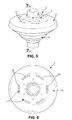
- FIG. 5 is a perspective view of a differential case assembly according to another embodiment of the present disclosure, the differential case assembly having an integral end cap and ring gear assembly;
- FIG. 6 is a top plan view of the differential case assembly shown in FIG. 5 ;
- FIG. 7 is a side cross-sectional elevational view of the differential case assembly taken along section line 7-7 in FIG. 5 ;
- FIG. 8 is a fragmentary enlarged side cross-sectional view of the differential case assembly taken at call out 8 in FIG. 7 , and further showing a slot in the integral end cap and ring gear assembly that permits a welding of the differential case assembly.
- FIGS. 1-8 depict a differential case assembly 2 according to the present disclosure.
- the differential case assembly 2 advantageously permits a welding operation from at least one of from “below” the differential case assembly 2 ( FIGS. 1-4 ) and “above” the differential case assembly ( FIGS. 5-8 ), as desired.
- the differential case assembly 2 includes a differential case 4, an end cap 6, a ring gear 8, and a gear assembly 10.
- the differential case 4, the end cap 6, and the ring gear 8 cooperate to house the gear assembly 10.
- the gear assembly 10 may have a cross pin, for example, as disclosed in Assignee's co-pending U.S. Patent Application Serial No. 13/094,406 , or may be pinless, for example, as disclosed in Assignee's co-pending U.S. Patent Application Serial No. 13/174,971 , the entire disclosures of which are hereby incorporated herein by reference.
- the differential case 4 has an open end 12 and a side wall 14 with an exterior surface 16.
- the differential case 4 is a flow formed shell.
- Skilled artisans should appreciate that the flow forming process for manufacturing the differential case 4 results in a plastic deformation of the preform and a non-interrupted grain flow for the formed differential case 4. Through plastic deformation, the preform material undergoes work hardening and can become stronger than the original preform material.
- the flow formed differential case 4 furthermore has minimal porosity and can be made thinner by wall reduction, and significantly lighter in comparison to cast iron differential case assemblies known in the art. Other methods for forming the differential case 4 may also be used, as desired
- the end cap 6 and the ring gear 8 may be provided as a one piece, integral end cap and ring gear assembly 6, 8.
- the integral end cap and ring gear assembly 6,8 are disposed over the open end 12 of the differential case 4 and adjacent the exterior surface 16 of the side wall 14.
- the integral end cap and ring gear assembly 6, 8 may have an outwardly extending edge portion that permits the integral end cap and ring gear assembly 6, 8 to be placed over top of the differential case 4, while also disposing the outwardly extending edge portion adjacent the side wall 14 of the differential case 4.
- the integral end cap and ring gear assembly 6, 8 may be cold formed or hot formed, or formed by another suitable process, within the scope of the present disclosure.
- the integral end cap and ring gear assembly 6, 8 has a first interior portion 18 and a second interior portion 20.
- the first interior portion 18 of the integral end cap and ring gear assembly 6, 8 abuts the exterior surface 16 of the differential case 4.
- a portion of the exterior surface 16 that abuts the first interior portion 18 of the integral end cap and ring gear assembly 6, 8 may be defined by an outwardly extending lip 21 of the differential case 4 adjacent the open end 12 of the differential case 4.
- Other means for defining the portion of the exterior surface 16 that abuts the first interior portion 18 may also be used, as desired.
- the abutting of the exterior surface 16 and the first interior portion 18 defines a weld joint interface 22 of the differential case assembly 2.
- the second interior portion 20 of the integral end cap and ring gear assembly 6, 8 is spaced apart from the exterior surface 16.
- the second interior portion 20 and the exterior surface 16 together define a void 24 therebetween.
- the void 24 permits the welding operation of the differential case 4 to the integral end cap and ring gear assembly 6, 8 from "below" the differential case assembly 2, at the weld joint interface 22.
- the weld joint interface 22 be disposed along a plane A facilitates the welding operation of the weld joint interface 22.
- the plane A is oriented at an acute angle relative to a vertical plane V.
- the weld joint interface 22 is angled or tapered and permits the integral end cap and ring gear assembly 6, 8 to be pressed into the differential case 4 during assembly.
- a surface of the second interior portion 20 of the integral end cap and ring gear assembly 6, 8 may also be parallel with the plane A, for the purpose of facilitating welding access to the weld joint interface 22.
- the vertical plane V may be substantially parallel to exterior surface 16 of the side wall 14 adjacent the second interior portion 20 of the integral end cap and ring gear assembly 6, 8.
- the angle may particularly be up to about 15 degrees, more particularly between about 5-10 degrees, and most particularly about 7.5 degrees.
- One of ordinary skill in the art may select other suitable angles for the acute angle of the plane A, as desired.
- a base 26 of the lip 21 is disposed on a plane B.
- the plane B is oriented orthogonal to the plane A of the portion of the exterior surface 16 that abuts the first interior portion 18 of the integral end cap and ring gear assembly 6, 8.
- a means for welding such as a laser is used for the welding operation, and the means for welding is oriented along the plane A, in line with the weld joint interface 22, the base 26 being disposed on the plane B results in a more consistent heating and welding at the weld joint interface 22.
- the differential case assembly 2 may further include a minor void 30 at the weld joint interface 22.
- the minor void 30 is disposed between exterior surface 16 of the side wall 14 of the differential case 4 and the first interior portion 18 of the integral end cap and ring gear assembly 6, 8.
- the minor void 30 may be defined by grooves formed in at least one of the exterior surface 16 and the first interior portion 18.
- the minor void 30 permits a collection of gases that may be generated during the welding operation, and facilitates the formation of a superior weld at the weld joint interface 22.
- the differential case assembly 2 of the present disclosure may also permit the welding operation from “above” the differential case assembly 2.
- the welding operation may be performed through a plurality of slots 32 that are formed in the integral end cap and ring gear assembly 6, 8.
- the slots 32 may permit access to both the differential case 4 and the integral end cap and ring gear assembly 6, 8 for the welding operation.
- the slots 32 are also spaced apart, which results in a series of stitch-type or intermittent welds during the welding operation.
- the present disclosure also includes a method for manufacturing the differential case assembly 2.
- the method first includes the steps of providing the differential case 4 and disposing the integral end cap and ring gear assembly 6, 8 over the open end 12 of the differential case 4 and adjacent the exterior surface 16 of the side wall 14 of the differential case 4.
- the disposing of the integral end cap and ring gear assembly 6, 8 over the open end 12 of the differential case 4 results in an abutting of the differential case 4 and the integral end cap and ring gear assembly 6, 8, and the subsequent formation of a weld joint interface 22.
- the differential case assembly 2 may be configured for at least one of the "below” welding operation and the "above” welding operation at the weld joint interface 22, as described hereinabove. Accordingly, the method for manufacturing the differential case assembly 2 further includes the step of welding the differential case 4 with the integral end cap and ring gear assembly 6, 8 at the weld joint interface 22, either through the void 24 below the weld joint interface 22 or through the slots 32 above the weld joint interface 22.
- the welding operation is a laser welding operation.
- one of ordinary skill in the art may select other suitable means for welding during the welding operation, as desired.
- the differential case assembly 2 of the present disclosure is less massive and more volumetrically efficient than differentials for motorized vehicles that are known in the art.
- the differential case assembly 2 may be manufactured without the use of screws, bolts, rivets, or the like.
Landscapes
- Engineering & Computer Science (AREA)
- General Engineering & Computer Science (AREA)
- Mechanical Engineering (AREA)
- Retarders (AREA)
- Laser Beam Processing (AREA)
Abstract
Description
- This application claims the benefit of
U.S. Provisional Patent Application No. 61/499,929 filed on June 22, 2011 - The present disclosure relates to a differential case assembly and, more particularly, to a differential case assembly for use in a motorized vehicle.
- A differential is a device, usually employing gears, that is capable of transmitting torque and permitting rotation of different shafts at different speeds. Known differentials have cases that are cast from metals such as iron, and are often heavy and volumetrically undesirable. Assembly of known differentials can be difficult, oftentimes requiring bolting as well as welding. The use of "feed-in and rotate processes" when cast iron differential cases are manufactured is also known. Welding of the differentials formed from cast iron, in particular, can undesirably require the use of filler wire to provide an acceptable weld.
- A particular differential case assembly is described in Assignee's co-pending
U.S. Patent Application Publication No. 20110263374 to Cripsey, filed on April 26, 2011 , the entire disclosure of which is hereby incorporated herein by reference. The differential case assembly includes a differential case having an open end and a side wall with an interior surface, A plurality of major internal splines is formed on the interior surface of the side wall. The differential case assembly further includes a gear assembly. The gear assembly has a retainer insert and a cross pin. The retainer insert is disposed adjacent the interior surface of the side wall between a pair of the major internal splines. The retainer insert has a hole formed therein. The cross pin has an end mounted in the hole of the retainer insert. The cross pin aligns the gear assembly within the differential case. - There is a continuing need for a differential case assembly that is lighter compared to known cast iron designs, minimizes a required packaging space, minimizes assembly complexity, and can be employed with different numbers of gears. A differential case assembly that facilitates welding and eliminates a need for multiple nuts/bolts in the assembly process is also desired.
- In concordance with the instant disclosure, a differential case assembly that is lighter compared to known cast iron designs, minimizes a required packaging space, minimizes assembly complexity, can be employed with different numbers of gears, facilitates welding, and eliminates a need for multiple nuts/bolts in the assembly process, is surprisingly discovered.
- In one embodiment, a differential case assembly includes a differential case and an integral end cap and ring gear assembly. The differential case has an open end and a side wall with an exterior surface. The integral end cap and ring gear assembly is disposed over the open end of the differential case and adjacent the exterior surface. A first interior portion of the integral end cap and ring gear assembly abuts the exterior surface of the differential case to define a weld joint interface. A second interior portion of the integral end cap and ring gear assembly is spaced apart from the exterior surface and defines a void therebetween. The void permits a welding operation of the differential case to the integral end cap and ring gear assembly at the weld joint interface.
- In another embodiment, a differential case assembly includes a differential case and an integral end cap and ring gear assembly. The differential case has an open end and a side wall with an exterior surface. The integral end cap and ring gear assembly is disposed over the open end of the differential case and adjacent the exterior surface. A first interior portion of the integral end cap and ring gear assembly abuts the exterior surface of the differential case to define a weld joint interface. The integral end cap and ring gear assembly has a plurality of slots formed therein that permit access to both the differential case and the integral end cap and ring gear assembly for a welding operation at the weld joint interface.
- In a further embodiment, a method for manufacturing a differential case assembly includes the steps of: providing a differential case having an open end and a side wall with an exterior surface; and disposing an integral end cap and ring gear assembly over the open end of the differential case and adjacent the exterior surface. A first interior portion of the integral end cap and ring gear assembly abuts the exterior surface of the differential case to define a weld joint interface. The integral end cap and ring gear assembly further includes at least one of a second interior portion spaced apart from the exterior surface and defining a void therebetween, and a plurality of slots. Each of the void and the slots permits a welding operation of the differential case to the integral end cap and ring gear assembly at the weld joint interface. The method further includes the step of welding the differential case with the integral end cap and ring gear assembly at the weld joint interface.
- The above, as well as other advantages of the present disclosure, will become readily apparent to those skilled in the art from the following detailed description, particularly when considered in the light of the drawings described herein.
-
FIG. 1 is a perspective view of a differential case assembly according to one embodiment of the present disclosure, the differential case assembly having an integral end cap and ring gear assembly; -
FIG. 2 is a side elevational view of the differential case assembly shown inFIG. 1 ; -
FIG. 3 is a side cross-sectional elevational view of the differential case assembly taken along section line 3-3 inFIG. 1 ; -
FIG. 4 is a fragmentary enlarged side cross-sectional view of the differential case assembly taken at call out 4 inFIG. 3 , and further showing an angled void opening that permits a welding of the differential case assembly; -
FIG. 5 is a perspective view of a differential case assembly according to another embodiment of the present disclosure, the differential case assembly having an integral end cap and ring gear assembly; -
FIG. 6 is a top plan view of the differential case assembly shown inFIG. 5 ; -
FIG. 7 is a side cross-sectional elevational view of the differential case assembly taken along section line 7-7 inFIG. 5 ; and -
FIG. 8 is a fragmentary enlarged side cross-sectional view of the differential case assembly taken at call out 8 inFIG. 7 , and further showing a slot in the integral end cap and ring gear assembly that permits a welding of the differential case assembly. - The following description is merely exemplary in nature and is not intended to limit the present disclosure, application, or uses. It should also be understood that throughout the drawings, corresponding reference numerals indicate like or corresponding parts and features. In respect of the methods disclosed, the order of the steps presented is exemplary in nature, and thus, is not necessary or critical.
-
FIGS. 1-8 depict adifferential case assembly 2 according to the present disclosure. Thedifferential case assembly 2 advantageously permits a welding operation from at least one of from "below" the differential case assembly 2 (FIGS. 1-4 ) and "above" the differential case assembly (FIGS. 5-8 ), as desired. - The
differential case assembly 2 includes adifferential case 4, an end cap 6, aring gear 8, and agear assembly 10. Thedifferential case 4, the end cap 6, and thering gear 8 cooperate to house thegear assembly 10. It should be understood that thegear assembly 10 may have a cross pin, for example, as disclosed in Assignee's co-pendingU.S. Patent Application Serial No. 13/094,406 , or may be pinless, for example, as disclosed in Assignee's co-pendingU.S. Patent Application Serial No. 13/174,971 , the entire disclosures of which are hereby incorporated herein by reference. - As shown in
FIG. 3 , thedifferential case 4 has anopen end 12 and aside wall 14 with anexterior surface 16. In a nonlimiting example, thedifferential case 4 is a flow formed shell. Skilled artisans should appreciate that the flow forming process for manufacturing thedifferential case 4 results in a plastic deformation of the preform and a non-interrupted grain flow for the formeddifferential case 4. Through plastic deformation, the preform material undergoes work hardening and can become stronger than the original preform material. The flow formeddifferential case 4 furthermore has minimal porosity and can be made thinner by wall reduction, and significantly lighter in comparison to cast iron differential case assemblies known in the art. Other methods for forming thedifferential case 4 may also be used, as desired - The end cap 6 and the
ring gear 8 may be provided as a one piece, integral end cap andring gear assembly 6, 8. The integral end cap andring gear assembly 6,8 are disposed over theopen end 12 of thedifferential case 4 and adjacent theexterior surface 16 of theside wall 14. For example, the integral end cap andring gear assembly 6, 8 may have an outwardly extending edge portion that permits the integral end cap andring gear assembly 6, 8 to be placed over top of thedifferential case 4, while also disposing the outwardly extending edge portion adjacent theside wall 14 of thedifferential case 4. The integral end cap andring gear assembly 6, 8 may be cold formed or hot formed, or formed by another suitable process, within the scope of the present disclosure. - With reference to
FIGS. 1-4 , the integral end cap andring gear assembly 6, 8 has a firstinterior portion 18 and a secondinterior portion 20. The firstinterior portion 18 of the integral end cap andring gear assembly 6, 8 abuts theexterior surface 16 of thedifferential case 4. For example, a portion of theexterior surface 16 that abuts the firstinterior portion 18 of the integral end cap andring gear assembly 6, 8 may be defined by an outwardly extendinglip 21 of thedifferential case 4 adjacent theopen end 12 of thedifferential case 4. Other means for defining the portion of theexterior surface 16 that abuts the firstinterior portion 18 may also be used, as desired. - The abutting of the
exterior surface 16 and the firstinterior portion 18 defines a weldjoint interface 22 of thedifferential case assembly 2. The secondinterior portion 20 of the integral end cap andring gear assembly 6, 8 is spaced apart from theexterior surface 16. The secondinterior portion 20 and theexterior surface 16 together define a void 24 therebetween. The void 24 permits the welding operation of thedifferential case 4 to the integral end cap andring gear assembly 6, 8 from "below" thedifferential case assembly 2, at the weldjoint interface 22. - As illustrated in
FIGS. 3 and 4 , it has been surprising found that having the weldjoint interface 22 be disposed along a plane A facilitates the welding operation of the weldjoint interface 22. The plane A is oriented at an acute angle relative to a vertical plane V. As such, the weldjoint interface 22 is angled or tapered and permits the integral end cap andring gear assembly 6, 8 to be pressed into thedifferential case 4 during assembly. A surface of the secondinterior portion 20 of the integral end cap andring gear assembly 6, 8 may also be parallel with the plane A, for the purpose of facilitating welding access to the weldjoint interface 22. - As a nonlimiting example, the vertical plane V may be substantially parallel to
exterior surface 16 of theside wall 14 adjacent the secondinterior portion 20 of the integral end cap andring gear assembly 6, 8. The angle may particularly be up to about 15 degrees, more particularly between about 5-10 degrees, and most particularly about 7.5 degrees. One of ordinary skill in the art may select other suitable angles for the acute angle of the plane A, as desired. - Referring further to
FIGS. 3 and 4 , it is also surprisingly found that the welding operation is facilitated where abase 26 of thelip 21 is disposed on a plane B. The plane B is oriented orthogonal to the plane A of the portion of theexterior surface 16 that abuts the firstinterior portion 18 of the integral end cap andring gear assembly 6, 8. Where a means for welding such as a laser is used for the welding operation, and the means for welding is oriented along the plane A, in line with the weldjoint interface 22, thebase 26 being disposed on the plane B results in a more consistent heating and welding at the weldjoint interface 22. - As also shown in
FIGS. 3 and 4 , thedifferential case assembly 2 may further include aminor void 30 at the weldjoint interface 22. In particular, theminor void 30 is disposed betweenexterior surface 16 of theside wall 14 of thedifferential case 4 and the firstinterior portion 18 of the integral end cap andring gear assembly 6, 8. Theminor void 30 may be defined by grooves formed in at least one of theexterior surface 16 and the firstinterior portion 18. Theminor void 30 permits a collection of gases that may be generated during the welding operation, and facilitates the formation of a superior weld at the weldjoint interface 22. - Referring now to
FIGS. 5-8 , thedifferential case assembly 2 of the present disclosure may also permit the welding operation from "above" thedifferential case assembly 2. The welding operation may be performed through a plurality ofslots 32 that are formed in the integral end cap andring gear assembly 6, 8. For example, theslots 32 may permit access to both thedifferential case 4 and the integral end cap andring gear assembly 6, 8 for the welding operation. Theslots 32 are also spaced apart, which results in a series of stitch-type or intermittent welds during the welding operation. - In a particular embodiment illustrated in
FIGS. 7 and 8 , aledge 34 is formed in the integral retaining cap andring gear assembly 6, 8. Theledge 34 exposes the weldjoint interface 22 beneath each of theslots 32. In certain embodiments, theledge 34 provides an outer half of the weldjoint interface 22 exposed beneath each of theslots 32. Where the weldjoint interface 22 is exposed thusly, it should be appreciated that the welding operation may be performed from "above" thedifferential case assembly 2. The welding operation from "above" may be performed together with, or separate from, the welding operation performed from "below" on thedifferential case assembly 2. - The present disclosure also includes a method for manufacturing the
differential case assembly 2. The method first includes the steps of providing thedifferential case 4 and disposing the integral end cap andring gear assembly 6, 8 over theopen end 12 of thedifferential case 4 and adjacent theexterior surface 16 of theside wall 14 of thedifferential case 4. The disposing of the integral end cap andring gear assembly 6, 8 over theopen end 12 of thedifferential case 4 results in an abutting of thedifferential case 4 and the integral end cap andring gear assembly 6, 8, and the subsequent formation of a weldjoint interface 22. - The
differential case assembly 2 may be configured for at least one of the "below" welding operation and the "above" welding operation at the weldjoint interface 22, as described hereinabove. Accordingly, the method for manufacturing thedifferential case assembly 2 further includes the step of welding thedifferential case 4 with the integral end cap andring gear assembly 6, 8 at the weldjoint interface 22, either through the void 24 below the weldjoint interface 22 or through theslots 32 above the weldjoint interface 22. - In particular embodiments, the welding operation is a laser welding operation. However, one of ordinary skill in the art may select other suitable means for welding during the welding operation, as desired.
- Advantageously, the
differential case assembly 2 of the present disclosure is less massive and more volumetrically efficient than differentials for motorized vehicles that are known in the art. Furthermore, thedifferential case assembly 2 may be manufactured without the use of screws, bolts, rivets, or the like. - While certain representative embodiments and details have been shown for purposes of illustrating the invention, it will be apparent to those skilled in the art that various changes may be made without departing from the scope of the disclosure, which is further described in the following appended claims.
Claims (15)
- A differential case assembly (2), comprising:a differential case (4) having an open end (12) and a side wall (14) with an exterior surface (16);an integral end cap (6) and ring gear assembly (8) disposed over the open end (12) of the differential case (4) and adjacent the exterior surface (16), a first interior portion (18) of the integral end cap (6) and ring gear assembly (8) abutting the exterior surface (16) of the differential case (4) to define a weld joint interface (22) and a second interior portion (20) of the integral end cap (6) and ring gear assembly (8) spaced apart from the exterior surface (16) and defining a void (24) therebetween, the void (24) permitting a welding operation of the differential case (4) to the integral end cap (6) and ring gear assembly (8) at the weld joint interface (22).
- The differential case assembly (2) of Claim 1, wherein the exterior surface (16) abutting the first interior portion (18) is defined by a lip (21) of the differential case (4) adjacent the open end (12).
- The differential case assembly (2) of Claim 2, wherein weld joint interface (22) is disposed on a plane oriented at an acute angle relative to a vertical plane.
- The differential case assembly (2) of Claim 3, wherein the angle is up to about 15 degrees.
- The differential case assembly (2) of Claim 3, wherein a base of the lip (21) is disposed on a plane oriented orthogonal to the plane on which the weld joint interface (22) is disposed.
- The differential case assembly (2) of Claim 1, wherein the integral end cap (6) and ring gear assembly (8) has a plurality of slots (32) formed therein, the slots (32) permitting access to both the differential case (4) and the integral end cap (6) and ring gear assembly (8) for a welding operation, and a ledge (34) being formed in the integral retaining cap (6) and ring gear assembly (8), the ledge (34) exposing the weld joint interface (22) beneath each of the slots (32).
- The differential case assembly (2) of Claim 1, wherein the weld joint interface (22) has a minor void (30) disposed between the exterior surface (16) of the side wall (14) of the differential case (4) and first interior portion (18) of the integral end cap (6) and ring gear assembly (8), the minor void (30) permitting a collection of gases during the welding operation.
- A differential case assembly (2), comprising:a differential case (4) having an open end (12) and a side wall (14) with an exterior surface (16);an integral end cap (6) and ring gear assembly (8) disposed over the open end (12) of the differential case (4) and adjacent the exterior surface (16), a first interior portion (18) of the integral end cap (6) and ring gear assembly (8) abutting the exterior surface (16) of the differential case (4) to define a weld joint interface (22), the integral end cap (6) and ring gear assembly (8) having a plurality of slots (32) formed therein that permit access to both the differential case (4) and the integral end cap (6) and ring gear assembly (8) for a welding operation at the weld joint interface (22).
- The differential case assembly (2) of Claim 8, wherein a ledge (34) is formed in the integral retaining cap and ring gear assembly (8), the ledge (34) exposing the weld joint interface (22) beneath each of the slots (32).
- The differential case assembly (2) of Claim 8, wherein the weld joint interface (22) includes a minor void (3) disposed between the exterior surface (16) of the side wall (14) of the differential case (4) and the first interior portion (18) of the integral end cap (6) and ring gear assembly (8), the minor void (30) permitting a collection of gases during the welding operation.
- The differential case assembly (2) of Claim 8, wherein a second interior portion (20) of the integral end cap (6) and ring gear assembly (8) is spaced apart from the exterior surface (16) and defines a void (24) therebetween, the void (24) permitting a welding operation of the differential case (4) to the integral end cap (6) and ring gear assembly (8) at the weld joint interface (22), the first interior portion (18) of the exterior surface (16) being defined by a lip (21) of the differential case (4) adjacent the open end (12), and the weld joint interface (22) being disposed on a plane oriented at an acute angle relative to a vertical plane.
- The differential case assembly (2) of Claim 11, wherein the angle is up to about 15 degrees.
- The differential case assembly (2) of Claim 11, wherein a base of the lip (21) is disposed on a plane oriented orthogonal to the plane on which the weld joint interface (22) is disposed.
- A method for manufacturing a differential case assembly (2), the method comprising the steps of:providing a differential case (4) having an open end (12) and a side wall (14) with an exterior surface (16);disposing an integral end cap (6) and ring gear assembly (8) over the open end (12) of the differential case (4) and adjacent the exterior surface (16), a first interior portion (18) of the integral end cap (6) and ring gear assembly (8) abutting the exterior surface (16) of the differential case (4) to define a weld joint interface (22), wherein the integral end cap (6) and ring gear assembly (8) further includes at least one of
a second interior portion (20) spaced apart from the exterior surface (16) and defining a void (24) therebetween, the void (24) permitting a welding operation of the differential case (4) to the integral end cap (6) and ring gear assembly (8) at the weld joint interface (22), and
a plurality of slots (30) formed therein that permit access to both the differential case (4) and the integral end cap (6) and ring gear assembly (8) for the welding operation;welding the differential case (4) with the integral end cap (6) and ring gear assembly (8) at the weld joint interface (22). - The method of Claim 14, wherein the welding operation is a laser welding operation.
Applications Claiming Priority (1)
| Application Number | Priority Date | Filing Date | Title |
|---|---|---|---|
| US201161499929P | 2011-06-22 | 2011-06-22 |
Publications (2)
| Publication Number | Publication Date |
|---|---|
| EP2538119A1 true EP2538119A1 (en) | 2012-12-26 |
| EP2538119B1 EP2538119B1 (en) | 2016-12-21 |
Family
ID=46419908
Family Applications (1)
| Application Number | Title | Priority Date | Filing Date |
|---|---|---|---|
| EP12173051.9A Not-in-force EP2538119B1 (en) | 2011-06-22 | 2012-06-21 | Welded differential case assembly |
Country Status (4)
| Country | Link |
|---|---|
| US (1) | US9157516B2 (en) |
| EP (1) | EP2538119B1 (en) |
| CN (1) | CN102840300B (en) |
| CA (1) | CA2780125C (en) |
Cited By (5)
| Publication number | Priority date | Publication date | Assignee | Title |
|---|---|---|---|---|
| WO2017013321A1 (en) * | 2015-07-20 | 2017-01-26 | Renault S.A.S | Welded connection between a differential ring gear and casing of same |
| WO2017050375A1 (en) * | 2015-09-23 | 2017-03-30 | Gkn Driveline Köping Ab | Connecting assembly and method for producing a connecting assembly |
| WO2020119944A1 (en) * | 2018-12-11 | 2020-06-18 | Eaton Intelligent Power Limited | Differential assembly |
| WO2020182399A1 (en) * | 2019-03-12 | 2020-09-17 | Robert Bosch Gmbh | Differential gearbox |
| DE102022127223A1 (en) * | 2022-10-18 | 2024-04-18 | Dr. Ing. H.C. F. Porsche Aktiengesellschaft | Differential gear for a motor vehicle |
Families Citing this family (13)
| Publication number | Priority date | Publication date | Assignee | Title |
|---|---|---|---|---|
| WO2011089706A1 (en) * | 2010-01-22 | 2011-07-28 | トヨタ自動車株式会社 | Welded structure and welding method |
| US9239104B2 (en) | 2010-01-22 | 2016-01-19 | Toyota Jidosha Kabushiki Kaisha | Welded structure and welding method |
| DE102012004389B4 (en) * | 2012-03-03 | 2022-02-10 | Daimler Ag | Differential gear for a motor vehicle as a welded construction with different materials |
| US8827859B2 (en) | 2012-10-10 | 2014-09-09 | Eaton Corporation | Differential having two-piece case split through planetary carrier wall |
| JP6189745B2 (en) | 2013-12-27 | 2017-08-30 | 武蔵精密工業株式会社 | Manufacturing method of differential device |
| DE102015207141A1 (en) * | 2015-04-20 | 2016-10-20 | Magna powertrain gmbh & co kg | differential |
| US20160356372A1 (en) | 2015-06-08 | 2016-12-08 | Magna Powertrain Of America, Inc. | Differential assembly with single weld joint connecting two-piece differential case and ring gear |
| CN108603580B (en) | 2016-02-10 | 2021-11-23 | 麦格纳动力系美国有限公司 | Differential assembly with two-piece carrier and welded ring gear |
| CN107304802B (en) * | 2016-04-18 | 2019-09-17 | 本田技研工业株式会社 | Differential gear |
| DE102017207126A1 (en) * | 2016-07-25 | 2018-01-25 | Deere & Company | Drive arrangement with a rotating housing connected to an output interface |
| US10781908B2 (en) * | 2017-12-11 | 2020-09-22 | Gkn Automotive Limited | Driveline components with weld vent |
| US11511876B2 (en) * | 2018-12-03 | 2022-11-29 | Textron Innovations Inc. | Variable porosity load-bearing and heat-dissipating aircraft structures |
| CN120759917B (en) * | 2025-09-11 | 2026-01-09 | 四川丹齿精工科技有限公司 | A gearbox assembly |
Citations (2)
| Publication number | Priority date | Publication date | Assignee | Title |
|---|---|---|---|---|
| DE102008017221A1 (en) * | 2007-04-05 | 2008-10-09 | Neumayer Tekfor Holding Gmbh | Differential provided with a drive wheel |
| US20110263374A1 (en) | 2010-04-27 | 2011-10-27 | Cripsey Timothy J | Flow-formed differential case assembly |
Family Cites Families (21)
| Publication number | Priority date | Publication date | Assignee | Title |
|---|---|---|---|---|
| JPS5166629A (en) * | 1974-12-02 | 1976-06-09 | Toyota Motor Co Ltd | |
| US5320587A (en) * | 1993-02-17 | 1994-06-14 | General Motors Corporation | Differential case with ring gear attachment |
| WO1999058287A1 (en) * | 1998-05-12 | 1999-11-18 | Steyr-Daimler-Puch Fahrzeugtechnik Ag & Co. Kg | Method for joining a cast part and a case-hardened steel part and component manufactured according to said method |
| EP1488134A4 (en) | 2002-03-05 | 2005-04-06 | Metal Forming & Coining Corp | Pinion carrier for planetary gear train and method of making same |
| WO2003076826A2 (en) | 2002-03-05 | 2003-09-18 | Metal Forming & Coining Corporation | Process for forming an internally splined part |
| AU2003209066A1 (en) | 2002-03-05 | 2003-09-22 | Metal Forming And Coining Corporation | Annulus gear and drive shell |
| JP2003314512A (en) * | 2002-04-25 | 2003-11-06 | Jatco Ltd | Fitting mechanism of automatic transmission |
| US7213435B2 (en) | 2002-06-21 | 2007-05-08 | Metal Forming & Coining Corporation | Splined clutch hub and method of making same |
| DE60305948T2 (en) * | 2002-09-27 | 2006-10-19 | Tesma International Inc., Concord | METHOD FOR PRODUCING A COLD-DRAWN DIFFERENTIAL HOUSING WITH INTEGRATED TOOTHPIECE |
| CA2508768A1 (en) * | 2002-12-05 | 2004-06-24 | Joseph A. Szuba | Differential mechanism for a vehicle |
| WO2004065822A2 (en) | 2003-01-15 | 2004-08-05 | Metal Forming & Coining Corporation | Torque transmitting assembly and method of producing |
| US20050009662A1 (en) * | 2003-06-08 | 2005-01-13 | Tochigi Fuji Sangyo Kabushiki Kaisha | Casing structure for torque transmission device |
| US7008345B2 (en) * | 2003-10-27 | 2006-03-07 | Automotive Components Holdings Inc. | Planetary differential |
| US7261664B2 (en) * | 2003-12-05 | 2007-08-28 | Ronjo Company, Llc | Differential mechanism for a vehicle and method of forming the same |
| DE102005023230B4 (en) * | 2005-05-04 | 2010-10-07 | Bayerische Motoren Werke Aktiengesellschaft | Method for welding a ring gear with a differential housing of a transmission |
| CA2818924C (en) | 2005-08-31 | 2014-06-10 | Metal Forming & Coining Corporation | Method of producing a flow formed part suitable for burr free machining |
| GB0601720D0 (en) * | 2006-01-27 | 2006-03-08 | Meritor Heavy Vehicle Sys Ltd | Differential Gear Assembly And Method |
| US8480531B2 (en) * | 2007-02-02 | 2013-07-09 | Arvinmeritor Technology, Llc | Differential assembly with inverted bearing |
| DE102007021437A1 (en) * | 2007-05-08 | 2008-11-13 | ThyssenKrupp Präzisionsschmiede GmbH | Differential in lightweight construction for motor vehicles |
| WO2009134667A1 (en) * | 2008-04-29 | 2009-11-05 | Transform Automotive Llc | Laser welded differential casings for vehicle axles |
| US8628444B2 (en) | 2010-07-01 | 2014-01-14 | Metal Forming & Coining Corporation | Flow-formed differential case assembly |
-
2012
- 2012-06-18 CA CA2780125A patent/CA2780125C/en active Active
- 2012-06-21 CN CN201210211256.8A patent/CN102840300B/en active Active
- 2012-06-21 EP EP12173051.9A patent/EP2538119B1/en not_active Not-in-force
- 2012-06-21 US US13/529,351 patent/US9157516B2/en active Active
Patent Citations (2)
| Publication number | Priority date | Publication date | Assignee | Title |
|---|---|---|---|---|
| DE102008017221A1 (en) * | 2007-04-05 | 2008-10-09 | Neumayer Tekfor Holding Gmbh | Differential provided with a drive wheel |
| US20110263374A1 (en) | 2010-04-27 | 2011-10-27 | Cripsey Timothy J | Flow-formed differential case assembly |
Cited By (8)
| Publication number | Priority date | Publication date | Assignee | Title |
|---|---|---|---|---|
| WO2017013321A1 (en) * | 2015-07-20 | 2017-01-26 | Renault S.A.S | Welded connection between a differential ring gear and casing of same |
| FR3039242A1 (en) * | 2015-07-20 | 2017-01-27 | Renault Sa | WELDED CONNECTION BETWEEN A DIFFERENTIAL CROWN AND ITS HOUSING |
| WO2017050375A1 (en) * | 2015-09-23 | 2017-03-30 | Gkn Driveline Köping Ab | Connecting assembly and method for producing a connecting assembly |
| CN108351012A (en) * | 2015-09-23 | 2018-07-31 | 吉凯恩传动系统雪平公司 | Connected component and method for producing connected component |
| WO2020119944A1 (en) * | 2018-12-11 | 2020-06-18 | Eaton Intelligent Power Limited | Differential assembly |
| WO2020182399A1 (en) * | 2019-03-12 | 2020-09-17 | Robert Bosch Gmbh | Differential gearbox |
| US11703114B2 (en) | 2019-03-12 | 2023-07-18 | Robert Bosch Gmbh | Differential gearbox |
| DE102022127223A1 (en) * | 2022-10-18 | 2024-04-18 | Dr. Ing. H.C. F. Porsche Aktiengesellschaft | Differential gear for a motor vehicle |
Also Published As
| Publication number | Publication date |
|---|---|
| CA2780125A1 (en) | 2012-12-22 |
| US9157516B2 (en) | 2015-10-13 |
| CN102840300B (en) | 2016-12-21 |
| CN102840300A (en) | 2012-12-26 |
| US20120325047A1 (en) | 2012-12-27 |
| CA2780125C (en) | 2016-10-04 |
| EP2538119B1 (en) | 2016-12-21 |
Similar Documents
| Publication | Publication Date | Title |
|---|---|---|
| EP2538119B1 (en) | Welded differential case assembly | |
| US9039560B2 (en) | Flow-formed differential case assembly | |
| CA2738258C (en) | Flow-formed differential case assembly | |
| US20030196468A1 (en) | Method of making a flanged tubular metallic part | |
| WO2008106591A1 (en) | Metal blank with binder trim component and method | |
| EP2695686A1 (en) | An axle housing and a method of manufacture | |
| US20140116668A1 (en) | Cooler pipe and method of forming | |
| US10352374B2 (en) | Method of forming and machining a clutch hub | |
| US7261664B2 (en) | Differential mechanism for a vehicle and method of forming the same | |
| US12214400B2 (en) | Method of forming a splined component | |
| US20140083922A1 (en) | Anti-rotation knurls | |
| CA2818924C (en) | Method of producing a flow formed part suitable for burr free machining | |
| CN107178562B (en) | Clutch ring gear assembly and method of construction thereof | |
| US10518817B2 (en) | Method for producing a joint connection between a joint housing and a connection component and suspension component and chassis produced according to the method | |
| US8042370B2 (en) | Flow formed gear | |
| US7766575B2 (en) | Internally splined part | |
| HK1179324A (en) | Flow-formed differential case assembly | |
| US20150322842A1 (en) | Sub-muffler and manufacturing method of sub-muffler | |
| US20110185782A1 (en) | Flow form tool mandrel | |
| CN110395073B (en) | One-piece axle shaft and method of making same | |
| JP2005155857A (en) | Method of manufacturing clutch housing | |
| US20070163319A1 (en) | Method for the production of a hollow profile provided with a terminal lid, and jack console | |
| CN1102692A (en) | Differential housing in axle housing | |
| JPH01293936A (en) | Manufacture of cylindrical part having groove | |
| JP2009154179A (en) | Double-sided protruding cylindrical part molding method from flat plate and double-sided protruding cylindrical part integrally molded product |
Legal Events
| Date | Code | Title | Description |
|---|---|---|---|
| PUAI | Public reference made under article 153(3) epc to a published international application that has entered the european phase |
Free format text: ORIGINAL CODE: 0009012 |
|
| AK | Designated contracting states |
Kind code of ref document: A1 Designated state(s): AL AT BE BG CH CY CZ DE DK EE ES FI FR GB GR HR HU IE IS IT LI LT LU LV MC MK MT NL NO PL PT RO RS SE SI SK SM TR |
|
| AX | Request for extension of the european patent |
Extension state: BA ME |
|
| 17P | Request for examination filed |
Effective date: 20130416 |
|
| 17Q | First examination report despatched |
Effective date: 20140102 |
|
| GRAP | Despatch of communication of intention to grant a patent |
Free format text: ORIGINAL CODE: EPIDOSNIGR1 |
|
| INTG | Intention to grant announced |
Effective date: 20160831 |
|
| GRAS | Grant fee paid |
Free format text: ORIGINAL CODE: EPIDOSNIGR3 |
|
| GRAA | (expected) grant |
Free format text: ORIGINAL CODE: 0009210 |
|
| AK | Designated contracting states |
Kind code of ref document: B1 Designated state(s): AL AT BE BG CH CY CZ DE DK EE ES FI FR GB GR HR HU IE IS IT LI LT LU LV MC MK MT NL NO PL PT RO RS SE SI SK SM TR |
|
| REG | Reference to a national code |
Ref country code: GB Ref legal event code: FG4D |
|
| REG | Reference to a national code |
Ref country code: CH Ref legal event code: EP |
|
| REG | Reference to a national code |
Ref country code: IE Ref legal event code: FG4D |
|
| REG | Reference to a national code |
Ref country code: AT Ref legal event code: REF Ref document number: 855798 Country of ref document: AT Kind code of ref document: T Effective date: 20170115 |
|
| REG | Reference to a national code |
Ref country code: DE Ref legal event code: R096 Ref document number: 602012026775 Country of ref document: DE |
|
| PG25 | Lapsed in a contracting state [announced via postgrant information from national office to epo] |
Ref country code: LV Free format text: LAPSE BECAUSE OF FAILURE TO SUBMIT A TRANSLATION OF THE DESCRIPTION OR TO PAY THE FEE WITHIN THE PRESCRIBED TIME-LIMIT Effective date: 20161221 |
|
| REG | Reference to a national code |
Ref country code: LT Ref legal event code: MG4D |
|
| REG | Reference to a national code |
Ref country code: NL Ref legal event code: MP Effective date: 20161221 |
|
| PG25 | Lapsed in a contracting state [announced via postgrant information from national office to epo] |
Ref country code: NO Free format text: LAPSE BECAUSE OF FAILURE TO SUBMIT A TRANSLATION OF THE DESCRIPTION OR TO PAY THE FEE WITHIN THE PRESCRIBED TIME-LIMIT Effective date: 20170321 Ref country code: GR Free format text: LAPSE BECAUSE OF FAILURE TO SUBMIT A TRANSLATION OF THE DESCRIPTION OR TO PAY THE FEE WITHIN THE PRESCRIBED TIME-LIMIT Effective date: 20170322 Ref country code: SE Free format text: LAPSE BECAUSE OF FAILURE TO SUBMIT A TRANSLATION OF THE DESCRIPTION OR TO PAY THE FEE WITHIN THE PRESCRIBED TIME-LIMIT Effective date: 20161221 Ref country code: LT Free format text: LAPSE BECAUSE OF FAILURE TO SUBMIT A TRANSLATION OF THE DESCRIPTION OR TO PAY THE FEE WITHIN THE PRESCRIBED TIME-LIMIT Effective date: 20161221 |
|
| REG | Reference to a national code |
Ref country code: AT Ref legal event code: MK05 Ref document number: 855798 Country of ref document: AT Kind code of ref document: T Effective date: 20161221 |
|
| PG25 | Lapsed in a contracting state [announced via postgrant information from national office to epo] |
Ref country code: HR Free format text: LAPSE BECAUSE OF FAILURE TO SUBMIT A TRANSLATION OF THE DESCRIPTION OR TO PAY THE FEE WITHIN THE PRESCRIBED TIME-LIMIT Effective date: 20161221 Ref country code: FI Free format text: LAPSE BECAUSE OF FAILURE TO SUBMIT A TRANSLATION OF THE DESCRIPTION OR TO PAY THE FEE WITHIN THE PRESCRIBED TIME-LIMIT Effective date: 20161221 Ref country code: RS Free format text: LAPSE BECAUSE OF FAILURE TO SUBMIT A TRANSLATION OF THE DESCRIPTION OR TO PAY THE FEE WITHIN THE PRESCRIBED TIME-LIMIT Effective date: 20161221 |
|
| PG25 | Lapsed in a contracting state [announced via postgrant information from national office to epo] |
Ref country code: NL Free format text: LAPSE BECAUSE OF FAILURE TO SUBMIT A TRANSLATION OF THE DESCRIPTION OR TO PAY THE FEE WITHIN THE PRESCRIBED TIME-LIMIT Effective date: 20161221 |
|
| PG25 | Lapsed in a contracting state [announced via postgrant information from national office to epo] |
Ref country code: CZ Free format text: LAPSE BECAUSE OF FAILURE TO SUBMIT A TRANSLATION OF THE DESCRIPTION OR TO PAY THE FEE WITHIN THE PRESCRIBED TIME-LIMIT Effective date: 20161221 Ref country code: SK Free format text: LAPSE BECAUSE OF FAILURE TO SUBMIT A TRANSLATION OF THE DESCRIPTION OR TO PAY THE FEE WITHIN THE PRESCRIBED TIME-LIMIT Effective date: 20161221 Ref country code: EE Free format text: LAPSE BECAUSE OF FAILURE TO SUBMIT A TRANSLATION OF THE DESCRIPTION OR TO PAY THE FEE WITHIN THE PRESCRIBED TIME-LIMIT Effective date: 20161221 Ref country code: IS Free format text: LAPSE BECAUSE OF FAILURE TO SUBMIT A TRANSLATION OF THE DESCRIPTION OR TO PAY THE FEE WITHIN THE PRESCRIBED TIME-LIMIT Effective date: 20170421 Ref country code: RO Free format text: LAPSE BECAUSE OF FAILURE TO SUBMIT A TRANSLATION OF THE DESCRIPTION OR TO PAY THE FEE WITHIN THE PRESCRIBED TIME-LIMIT Effective date: 20161221 |
|
| PG25 | Lapsed in a contracting state [announced via postgrant information from national office to epo] |
Ref country code: IT Free format text: LAPSE BECAUSE OF FAILURE TO SUBMIT A TRANSLATION OF THE DESCRIPTION OR TO PAY THE FEE WITHIN THE PRESCRIBED TIME-LIMIT Effective date: 20161221 Ref country code: PT Free format text: LAPSE BECAUSE OF FAILURE TO SUBMIT A TRANSLATION OF THE DESCRIPTION OR TO PAY THE FEE WITHIN THE PRESCRIBED TIME-LIMIT Effective date: 20170421 Ref country code: BG Free format text: LAPSE BECAUSE OF FAILURE TO SUBMIT A TRANSLATION OF THE DESCRIPTION OR TO PAY THE FEE WITHIN THE PRESCRIBED TIME-LIMIT Effective date: 20170321 Ref country code: AT Free format text: LAPSE BECAUSE OF FAILURE TO SUBMIT A TRANSLATION OF THE DESCRIPTION OR TO PAY THE FEE WITHIN THE PRESCRIBED TIME-LIMIT Effective date: 20161221 Ref country code: SM Free format text: LAPSE BECAUSE OF FAILURE TO SUBMIT A TRANSLATION OF THE DESCRIPTION OR TO PAY THE FEE WITHIN THE PRESCRIBED TIME-LIMIT Effective date: 20161221 Ref country code: PL Free format text: LAPSE BECAUSE OF FAILURE TO SUBMIT A TRANSLATION OF THE DESCRIPTION OR TO PAY THE FEE WITHIN THE PRESCRIBED TIME-LIMIT Effective date: 20161221 Ref country code: BE Free format text: LAPSE BECAUSE OF FAILURE TO SUBMIT A TRANSLATION OF THE DESCRIPTION OR TO PAY THE FEE WITHIN THE PRESCRIBED TIME-LIMIT Effective date: 20161221 Ref country code: ES Free format text: LAPSE BECAUSE OF FAILURE TO SUBMIT A TRANSLATION OF THE DESCRIPTION OR TO PAY THE FEE WITHIN THE PRESCRIBED TIME-LIMIT Effective date: 20161221 |
|
| REG | Reference to a national code |
Ref country code: DE Ref legal event code: R097 Ref document number: 602012026775 Country of ref document: DE |
|
| PLBE | No opposition filed within time limit |
Free format text: ORIGINAL CODE: 0009261 |
|
| STAA | Information on the status of an ep patent application or granted ep patent |
Free format text: STATUS: NO OPPOSITION FILED WITHIN TIME LIMIT |
|
| 26N | No opposition filed |
Effective date: 20170922 |
|
| PG25 | Lapsed in a contracting state [announced via postgrant information from national office to epo] |
Ref country code: DK Free format text: LAPSE BECAUSE OF FAILURE TO SUBMIT A TRANSLATION OF THE DESCRIPTION OR TO PAY THE FEE WITHIN THE PRESCRIBED TIME-LIMIT Effective date: 20161221 |
|
| PG25 | Lapsed in a contracting state [announced via postgrant information from national office to epo] |
Ref country code: MC Free format text: LAPSE BECAUSE OF FAILURE TO SUBMIT A TRANSLATION OF THE DESCRIPTION OR TO PAY THE FEE WITHIN THE PRESCRIBED TIME-LIMIT Effective date: 20161221 |
|
| REG | Reference to a national code |
Ref country code: CH Ref legal event code: PL |
|
| GBPC | Gb: european patent ceased through non-payment of renewal fee |
Effective date: 20170621 |
|
| PG25 | Lapsed in a contracting state [announced via postgrant information from national office to epo] |
Ref country code: SI Free format text: LAPSE BECAUSE OF FAILURE TO SUBMIT A TRANSLATION OF THE DESCRIPTION OR TO PAY THE FEE WITHIN THE PRESCRIBED TIME-LIMIT Effective date: 20161221 |
|
| REG | Reference to a national code |
Ref country code: IE Ref legal event code: MM4A |
|
| REG | Reference to a national code |
Ref country code: FR Ref legal event code: ST Effective date: 20180228 |
|
| PG25 | Lapsed in a contracting state [announced via postgrant information from national office to epo] |
Ref country code: IE Free format text: LAPSE BECAUSE OF NON-PAYMENT OF DUE FEES Effective date: 20170621 Ref country code: GB Free format text: LAPSE BECAUSE OF NON-PAYMENT OF DUE FEES Effective date: 20170621 Ref country code: LU Free format text: LAPSE BECAUSE OF NON-PAYMENT OF DUE FEES Effective date: 20170621 Ref country code: LI Free format text: LAPSE BECAUSE OF NON-PAYMENT OF DUE FEES Effective date: 20170630 Ref country code: CH Free format text: LAPSE BECAUSE OF NON-PAYMENT OF DUE FEES Effective date: 20170630 |
|
| PG25 | Lapsed in a contracting state [announced via postgrant information from national office to epo] |
Ref country code: FR Free format text: LAPSE BECAUSE OF NON-PAYMENT OF DUE FEES Effective date: 20170630 |
|
| PG25 | Lapsed in a contracting state [announced via postgrant information from national office to epo] |
Ref country code: MT Free format text: LAPSE BECAUSE OF NON-PAYMENT OF DUE FEES Effective date: 20170621 |
|
| PG25 | Lapsed in a contracting state [announced via postgrant information from national office to epo] |
Ref country code: HU Free format text: LAPSE BECAUSE OF FAILURE TO SUBMIT A TRANSLATION OF THE DESCRIPTION OR TO PAY THE FEE WITHIN THE PRESCRIBED TIME-LIMIT; INVALID AB INITIO Effective date: 20120621 |
|
| PG25 | Lapsed in a contracting state [announced via postgrant information from national office to epo] |
Ref country code: CY Free format text: LAPSE BECAUSE OF NON-PAYMENT OF DUE FEES Effective date: 20161221 |
|
| PG25 | Lapsed in a contracting state [announced via postgrant information from national office to epo] |
Ref country code: MK Free format text: LAPSE BECAUSE OF FAILURE TO SUBMIT A TRANSLATION OF THE DESCRIPTION OR TO PAY THE FEE WITHIN THE PRESCRIBED TIME-LIMIT Effective date: 20161221 |
|
| PG25 | Lapsed in a contracting state [announced via postgrant information from national office to epo] |
Ref country code: TR Free format text: LAPSE BECAUSE OF FAILURE TO SUBMIT A TRANSLATION OF THE DESCRIPTION OR TO PAY THE FEE WITHIN THE PRESCRIBED TIME-LIMIT Effective date: 20161221 |
|
| PG25 | Lapsed in a contracting state [announced via postgrant information from national office to epo] |
Ref country code: AL Free format text: LAPSE BECAUSE OF FAILURE TO SUBMIT A TRANSLATION OF THE DESCRIPTION OR TO PAY THE FEE WITHIN THE PRESCRIBED TIME-LIMIT Effective date: 20161221 |
|
| REG | Reference to a national code |
Ref country code: DE Ref legal event code: R081 Ref document number: 602012026775 Country of ref document: DE Owner name: METAL FORMING & COINING, LLC, MAUMEE, US Free format text: FORMER OWNER: METAL FORMING & COINING CORPORATION, MAUMEE, OHIO, US |
|
| PGFP | Annual fee paid to national office [announced via postgrant information from national office to epo] |
Ref country code: DE Payment date: 20240604 Year of fee payment: 13 |
|
| REG | Reference to a national code |
Ref country code: DE Ref legal event code: R119 Ref document number: 602012026775 Country of ref document: DE |
|
| PG25 | Lapsed in a contracting state [announced via postgrant information from national office to epo] |
Ref country code: DE Free format text: LAPSE BECAUSE OF NON-PAYMENT OF DUE FEES Effective date: 20260101 |