EP2544912B1 - Gitarrenhals - Google Patents
Gitarrenhals Download PDFInfo
- Publication number
- EP2544912B1 EP2544912B1 EP11752765.5A EP11752765A EP2544912B1 EP 2544912 B1 EP2544912 B1 EP 2544912B1 EP 11752765 A EP11752765 A EP 11752765A EP 2544912 B1 EP2544912 B1 EP 2544912B1
- Authority
- EP
- European Patent Office
- Prior art keywords
- valve cartridge
- sleeve
- end portion
- system component
- fuel system
- Prior art date
- Legal status (The legal status is an assumption and is not a legal conclusion. Google has not performed a legal analysis and makes no representation as to the accuracy of the status listed.)
- Not-in-force
Links
- 239000000446 fuel Substances 0.000 claims description 63
- 238000005538 encapsulation Methods 0.000 claims description 36
- 238000000034 method Methods 0.000 claims description 14
- 239000012530 fluid Substances 0.000 claims description 6
- 238000000071 blow moulding Methods 0.000 claims description 4
- 238000002788 crimping Methods 0.000 claims description 2
- 239000002828 fuel tank Substances 0.000 description 31
- 239000002184 metal Substances 0.000 description 9
- 239000007788 liquid Substances 0.000 description 6
- 239000000463 material Substances 0.000 description 6
- 238000000465 moulding Methods 0.000 description 5
- 239000000945 filler Substances 0.000 description 4
- 230000035699 permeability Effects 0.000 description 4
- 238000007789 sealing Methods 0.000 description 4
- 238000003466 welding Methods 0.000 description 3
- 238000013459 approach Methods 0.000 description 2
- 230000000712 assembly Effects 0.000 description 1
- 238000000429 assembly Methods 0.000 description 1
- 230000004888 barrier function Effects 0.000 description 1
- 238000005260 corrosion Methods 0.000 description 1
- 230000007797 corrosion Effects 0.000 description 1
- 230000008878 coupling Effects 0.000 description 1
- 238000010168 coupling process Methods 0.000 description 1
- 238000005859 coupling reaction Methods 0.000 description 1
- 238000006073 displacement reaction Methods 0.000 description 1
- 238000003780 insertion Methods 0.000 description 1
- 230000037431 insertion Effects 0.000 description 1
- 239000011347 resin Substances 0.000 description 1
- 229920005989 resin Polymers 0.000 description 1
- 238000009423 ventilation Methods 0.000 description 1
Images


Classifications
-
- B—PERFORMING OPERATIONS; TRANSPORTING
- B60—VEHICLES IN GENERAL
- B60K—ARRANGEMENT OR MOUNTING OF PROPULSION UNITS OR OF TRANSMISSIONS IN VEHICLES; ARRANGEMENT OR MOUNTING OF PLURAL DIVERSE PRIME-MOVERS IN VEHICLES; AUXILIARY DRIVES FOR VEHICLES; INSTRUMENTATION OR DASHBOARDS FOR VEHICLES; ARRANGEMENTS IN CONNECTION WITH COOLING, AIR INTAKE, GAS EXHAUST OR FUEL SUPPLY OF PROPULSION UNITS IN VEHICLES
- B60K15/00—Arrangement in connection with fuel supply of combustion engines or other fuel consuming energy converters, e.g. fuel cells; Mounting or construction of fuel tanks
- B60K15/03—Fuel tanks
- B60K15/04—Tank inlets
-
- B—PERFORMING OPERATIONS; TRANSPORTING
- B60—VEHICLES IN GENERAL
- B60K—ARRANGEMENT OR MOUNTING OF PROPULSION UNITS OR OF TRANSMISSIONS IN VEHICLES; ARRANGEMENT OR MOUNTING OF PLURAL DIVERSE PRIME-MOVERS IN VEHICLES; AUXILIARY DRIVES FOR VEHICLES; INSTRUMENTATION OR DASHBOARDS FOR VEHICLES; ARRANGEMENTS IN CONNECTION WITH COOLING, AIR INTAKE, GAS EXHAUST OR FUEL SUPPLY OF PROPULSION UNITS IN VEHICLES
- B60K15/00—Arrangement in connection with fuel supply of combustion engines or other fuel consuming energy converters, e.g. fuel cells; Mounting or construction of fuel tanks
- B60K15/03—Fuel tanks
- B60K15/073—Tank construction specially adapted to the vehicle
-
- B—PERFORMING OPERATIONS; TRANSPORTING
- B60—VEHICLES IN GENERAL
- B60K—ARRANGEMENT OR MOUNTING OF PROPULSION UNITS OR OF TRANSMISSIONS IN VEHICLES; ARRANGEMENT OR MOUNTING OF PLURAL DIVERSE PRIME-MOVERS IN VEHICLES; AUXILIARY DRIVES FOR VEHICLES; INSTRUMENTATION OR DASHBOARDS FOR VEHICLES; ARRANGEMENTS IN CONNECTION WITH COOLING, AIR INTAKE, GAS EXHAUST OR FUEL SUPPLY OF PROPULSION UNITS IN VEHICLES
- B60K15/00—Arrangement in connection with fuel supply of combustion engines or other fuel consuming energy converters, e.g. fuel cells; Mounting or construction of fuel tanks
- B60K15/03—Fuel tanks
- B60K15/03177—Fuel tanks made of non-metallic material, e.g. plastics, or of a combination of non-metallic and metallic material
-
- B—PERFORMING OPERATIONS; TRANSPORTING
- B60—VEHICLES IN GENERAL
- B60K—ARRANGEMENT OR MOUNTING OF PROPULSION UNITS OR OF TRANSMISSIONS IN VEHICLES; ARRANGEMENT OR MOUNTING OF PLURAL DIVERSE PRIME-MOVERS IN VEHICLES; AUXILIARY DRIVES FOR VEHICLES; INSTRUMENTATION OR DASHBOARDS FOR VEHICLES; ARRANGEMENTS IN CONNECTION WITH COOLING, AIR INTAKE, GAS EXHAUST OR FUEL SUPPLY OF PROPULSION UNITS IN VEHICLES
- B60K15/00—Arrangement in connection with fuel supply of combustion engines or other fuel consuming energy converters, e.g. fuel cells; Mounting or construction of fuel tanks
- B60K15/03—Fuel tanks
- B60K2015/03328—Arrangements or special measures related to fuel tanks or fuel handling
- B60K2015/03447—Arrangements or special measures related to fuel tanks or fuel handling for improving the sealing
-
- B—PERFORMING OPERATIONS; TRANSPORTING
- B60—VEHICLES IN GENERAL
- B60K—ARRANGEMENT OR MOUNTING OF PROPULSION UNITS OR OF TRANSMISSIONS IN VEHICLES; ARRANGEMENT OR MOUNTING OF PLURAL DIVERSE PRIME-MOVERS IN VEHICLES; AUXILIARY DRIVES FOR VEHICLES; INSTRUMENTATION OR DASHBOARDS FOR VEHICLES; ARRANGEMENTS IN CONNECTION WITH COOLING, AIR INTAKE, GAS EXHAUST OR FUEL SUPPLY OF PROPULSION UNITS IN VEHICLES
- B60K15/00—Arrangement in connection with fuel supply of combustion engines or other fuel consuming energy converters, e.g. fuel cells; Mounting or construction of fuel tanks
- B60K15/03—Fuel tanks
- B60K2015/03328—Arrangements or special measures related to fuel tanks or fuel handling
- B60K2015/03453—Arrangements or special measures related to fuel tanks or fuel handling for fixing or mounting parts of the fuel tank together
-
- B—PERFORMING OPERATIONS; TRANSPORTING
- B60—VEHICLES IN GENERAL
- B60K—ARRANGEMENT OR MOUNTING OF PROPULSION UNITS OR OF TRANSMISSIONS IN VEHICLES; ARRANGEMENT OR MOUNTING OF PLURAL DIVERSE PRIME-MOVERS IN VEHICLES; AUXILIARY DRIVES FOR VEHICLES; INSTRUMENTATION OR DASHBOARDS FOR VEHICLES; ARRANGEMENTS IN CONNECTION WITH COOLING, AIR INTAKE, GAS EXHAUST OR FUEL SUPPLY OF PROPULSION UNITS IN VEHICLES
- B60K15/00—Arrangement in connection with fuel supply of combustion engines or other fuel consuming energy converters, e.g. fuel cells; Mounting or construction of fuel tanks
- B60K15/03—Fuel tanks
- B60K15/04—Tank inlets
- B60K2015/0458—Details of the tank inlet
- B60K2015/047—Manufacturing of the fuel inlet or connecting elements to fuel inlet, e.g. pipes or venting tubes
-
- B—PERFORMING OPERATIONS; TRANSPORTING
- B60—VEHICLES IN GENERAL
- B60K—ARRANGEMENT OR MOUNTING OF PROPULSION UNITS OR OF TRANSMISSIONS IN VEHICLES; ARRANGEMENT OR MOUNTING OF PLURAL DIVERSE PRIME-MOVERS IN VEHICLES; AUXILIARY DRIVES FOR VEHICLES; INSTRUMENTATION OR DASHBOARDS FOR VEHICLES; ARRANGEMENTS IN CONNECTION WITH COOLING, AIR INTAKE, GAS EXHAUST OR FUEL SUPPLY OF PROPULSION UNITS IN VEHICLES
- B60K15/00—Arrangement in connection with fuel supply of combustion engines or other fuel consuming energy converters, e.g. fuel cells; Mounting or construction of fuel tanks
- B60K15/03—Fuel tanks
- B60K15/04—Tank inlets
- B60K2015/0458—Details of the tank inlet
- B60K2015/0477—Details of the filler neck tank side
-
- Y—GENERAL TAGGING OF NEW TECHNOLOGICAL DEVELOPMENTS; GENERAL TAGGING OF CROSS-SECTIONAL TECHNOLOGIES SPANNING OVER SEVERAL SECTIONS OF THE IPC; TECHNICAL SUBJECTS COVERED BY FORMER USPC CROSS-REFERENCE ART COLLECTIONS [XRACs] AND DIGESTS
- Y10—TECHNICAL SUBJECTS COVERED BY FORMER USPC
- Y10T—TECHNICAL SUBJECTS COVERED BY FORMER US CLASSIFICATION
- Y10T137/00—Fluid handling
- Y10T137/0318—Processes
-
- Y—GENERAL TAGGING OF NEW TECHNOLOGICAL DEVELOPMENTS; GENERAL TAGGING OF CROSS-SECTIONAL TECHNOLOGIES SPANNING OVER SEVERAL SECTIONS OF THE IPC; TECHNICAL SUBJECTS COVERED BY FORMER USPC CROSS-REFERENCE ART COLLECTIONS [XRACs] AND DIGESTS
- Y10—TECHNICAL SUBJECTS COVERED BY FORMER USPC
- Y10T—TECHNICAL SUBJECTS COVERED BY FORMER US CLASSIFICATION
- Y10T137/00—Fluid handling
- Y10T137/598—With repair, tapping, assembly, or disassembly means
- Y10T137/6011—Assembling, disassembling, or removing cartridge type valve [e.g., insertable and removable as a unit, etc.]
-
- Y—GENERAL TAGGING OF NEW TECHNOLOGICAL DEVELOPMENTS; GENERAL TAGGING OF CROSS-SECTIONAL TECHNOLOGIES SPANNING OVER SEVERAL SECTIONS OF THE IPC; TECHNICAL SUBJECTS COVERED BY FORMER USPC CROSS-REFERENCE ART COLLECTIONS [XRACs] AND DIGESTS
- Y10—TECHNICAL SUBJECTS COVERED BY FORMER USPC
- Y10T—TECHNICAL SUBJECTS COVERED BY FORMER US CLASSIFICATION
- Y10T29/00—Metal working
- Y10T29/49—Method of mechanical manufacture
- Y10T29/49826—Assembling or joining
Definitions
- the disclosure relates to a neck assembly for a fuel system component, such as a fuel tank. Specifically, the disclosure relates to a neck assembly for a fuel system component that is made by blow molding.
- U.S. Pat. No. 6,860,398 discloses low permeation fittings and low permeation plastic containers using the low permeating fittings.
- the low permeation fittings and low permeation plastic containers are constructed by molding an outer component into the wall of a plastic container while it is being formed. This causes the opening of a passageway in the outer component to be covered with wall forming material.
- the inner component is then inserted into the outer component through the wall forming material thereby trapping the wall material between the internal and external components.
- the barrier layer of the container wall is therefore continuous from the container to inside the fitting.
- a new fuel container, fuel neck fitting, and flange for mounting components on a fuel tank are disclosed.
- US 2002/063129 A1 describes a neck assembly according to the preamble of claim 1, whereby a low permeability fitting for a low permeability container has a hollow inner component and a hollow outer component between which can be sandwiched a low permeability material that forms the wall of a low permeability container.
- a neck assembly of a fuel system component is provided as defined by the features of claim 1.
- the neck assembly comprises a housing.
- the housing comprises a sleeve having a first end portion positioned exterior to the fuel system component and a longitudinally opposed second end portion.
- the housing further comprises an encapsulation ring extending radially outwardly from the second end portion of the sleeve and encapsulated within a wall of the fuel system component.
- the neck assembly further comprises a valve cartridge at least partially received within the sleeve and secured thereto.
- the valve cartridge comprises a first end portion positioned exterior to the fuel system component and a longitudinally opposed second end portion.
- the valve cartridge defines a conduit for fluid flow. At least one separate annular seal is disposed between any two of the sleeve, the valve cartridge, and the wall of the fuel system component.
- the at least one annular seal may comprise a first seal disposed between the sleeve and the valve cartridge.
- the valve cartridge may comprise an outer surface and the sleeve may comprise an inner surface.
- the outer surface of the valve cartridge may be in facing relation to the inner surface of the sleeve.
- At least one of the outer surface of the valve cartridge and the inner surface of the sleeve may comprise a recess in which the first seal is seated.
- the neck assembly may further comprise a second annular seal disposed between the valve cartridge and the wall of the fuel system component.
- the valve cartridge may comprise a shoulder positioned in facing relation to an outer surface of the wall of the fuel system component, and the second seal may be disposed between the shoulder and the outer surface of the fuel system component
- the shoulder may comprise a recess in which the second seal is seated.
- the at least one annular seal may be made from a resiliently flexible material.
- the housing may further comprise at least one sleeve connector at the first end portion of the sleeve
- the valve cartridge may further comprise at least one valve cartridge connector at the first end portion of the valve cartridge.
- the valve cartridge connector may be engaged with the sleeve connector to secure the valve cartridge to the housing.
- the sleeve may be metal, and the encapsulation ring may be laser welded to the sleeve.
- the second end portion of the valve cartridge may extend proud of the second end portion of the sleeve and may be positioned within the fuel system component.
- the second end portion of the valve cartridge may have a valve assembly mounted thereto.
- the second end portion of the valve cartridge may include a valve.
- the valve may be selected from the group consisting of a rollover valve, a check valve, a fill limit vent valve, and a grade vent valve.
- the neck assembly comprises a housing.
- the housing comprises a sleeve having a first end portion positioned exterior to the fuel system component and a longitudinally opposed second end portion.
- An encapsulation ring extends outwardly from the second end portion of the sleeve and is encapsulated within a wall of the fuel system component.
- At least one sleeve connector is at the first end portion of the sleeve.
- the neck assembly further comprises a valve cartridge at least partially received within the sleeve and defining a conduit for fuel flow.
- the valve cartridge comprises a first end portion positioned exterior to the fuel system component and a longitudinally opposed second end portion.
- At least one valve cartridge connector is at the first end portion of the valve cartridge. The valve cartridge connector is engaged with the sleeve connector to secure the valve cartridge within the housing.
- the at least one sleeve connector may be integral with the sleeve, and the at least one valve cartridge connector may be integral with the valve cartridge.
- the at least one valve cartridge may comprise an outer surface, and at least one recess defined in the outer surface.
- the at least one sleeve connector may comprise at least one protrusion extending inwardly from the sleeve and protruding into the at least one recess.
- the at least one recess may comprise a plurality of recesses extending around the outer surface of the valve cartridge.
- the at least one protrusion may comprise a plurality of tabs extending inwardly from the sleeve. Each of the tabs may protrude into one of the recesses.
- the at least one recess may comprise a single annular recess extending around the outer surface of the valve cartridge.
- the at least one protrusion may comprise a plurality of tabs extending inwardly from the sleeve and protruding into the annular recess.
- the recess may comprise a base surface facing towards the first end portion of the conduit, and the tabs may have a proximal end connected to the sleeve and an opposed distal end that abuts the base surface.
- the sleeve may be a metal, and the plurality of tabs comprise may comprise cutouts that are bent into the recess upon assembly.
- the valve cartridge may comprise a lip having a first portion extending laterally radially outwardly from the first end portion of the valve cartridge and a second portion extending axially towards the second end portion of the valve cartridge.
- the lip may define a slot in which the first end portion of the sleeve is received.
- the sleeve connector may comprise at least one aperture formed through the first end portion of the sleeve, and the valve cartridge connector may comprise at least one protrusion extending inwardly from the second portion of the lip and received within the aperture.
- the lip may be resiliently flexible to allow for the protrusion to be removed from the aperture.
- the valve cartridge may be removably secured within the housing. In other words, the valve cartridge may be removable from the housing.
- the neck assembly comprises a housing.
- the housing comprises a metal sleeve having a first end portion positioned exterior to the fuel system component and a longitudinally opposed second end portion.
- the housing further comprises a metal encapsulation ring that is welded to the second end portion of the sleeve and extends radially outwardly from the second end portion of the sleeve.
- the encapsulation ring is encapsulated within a wall of the fuel system component.
- a valve cartridge is at least partially received within the sleeve and secured thereto.
- the valve cartridge defines a conduit for fuel flow, and comprises a first end portion positioned exterior to the fuel system component and a longitudinally opposed second end portion.
- a method for securing a neck assembly to a fuel system component comprises a) providing a housing comprising i) a sleeve having a first end portion and a longitudinally opposed second end portion, and (ii) an encapsulation ring extending radially outwardly from the second end portion of the sleeve; b) encapsulating the encapsulation ring in a wall of the fuel system component while blow-molding the fuel system component, whereby the first end portion of the sleeve is positioned exterior to the fuel system component; c) providing a valve cartridge defining a conduit for fuel flow and comprising a first end portion and a longitudinally opposed second end portion; d) inserting the valve cartridge into the sleeve from the first end portion of the sleeve towards the second end portion, whereby the first end portion of the valve cartridge is positioned exterior to the wall of the fuel system component; and e)
- the method may further comprise sealing the valve cartridge to at least one of the sleeve and the wall of the fuel system component.
- Sealing the valve cartridge to the sleeve may comprise mounting at least one separate annular seal to the valve cartridge prior to step (d), and compressing the at least one annular seal between the valve cartridge and one of the sleeve and the wall of the fuel system component during step (e).
- sealing the valve cartridge to the sleeve comprises mounting a first separate annular seal and a second separate annular seal to the valve cartridge prior to step (d), and compressing the first annular seal between the valve cartridge and the sleeve and the second annular seal between the valve cartridge and the wall of the fuel system component during step (e).
- the first end portion of the sleeve may comprise at least one tab.
- the valve cartridge may comprise an outer surface, and the first end portion of the valve cartridge may comprise at least one recess formed in the outer surface.
- Step (e) may comprise crimping the at least one tab into the at least one recess.
- the valve cartridge may comprise a lip having a first portion extending radially outwardly from the first end portion of the valve cartridge and a second portion extending axially towards the second end portion of the valve cartridge.
- the lip may a have slot.
- the method may further comprise inserting the first end portion of the sleeve into the slot while inserting the valve cartridge into the sleeve.
- At least one aperture may be formed through the first end portion of the sleeve.
- At least one protrusion may extend inwardly from the second portion of the lip. Step (e) may comprise snapping the protrusion into the aperture while inserting the valve cartridge into the sleeve.
- the sleeve may be metal
- the encapsulation ring may be metal
- step (a) may comprise laser welding the encapsulation ring to the second end portion of the sleeve.
- the method may further comprise mounting a valve assembly to the second end portion of the conduit prior to inserting the conduit into the sleeve.
- the fuel system component 10 is a fuel tank 13 for storing fuel.
- a fuel filler pipe 12 is provided for conveying fuel into the fuel tank 13.
- a ventilation system 14 aids in vapor displacement when introducing liquid fuel into the tank 10.
- An exit port 16 controls the release of the stored liquid fuel for use elsewhere in the system.
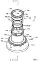
- a neck assembly 18 is used to connect the fuel tank 13 to the fuel filler pipe 12.
- the neck assembly 18 is secured to the fuel tank 13 by encapsulation.
- a portion of the assembly 18 is placed into the forming tool during the tank molding process and is exposed to the plastic of the fuel tank 13 while the plastic of the fuel tank 13 is in its liquid state so it can envelop, i.e. encapsulate, a portion of the neck assembly 18, thereby creating a hermetic seal between the two components.
- the neck assembly 18 includes a housing 20.
- the housing 20 includes a sleeve 26 (also known as a spud), and an encapsulation ring 24.
- the sleeve 26 is generally cylindrical, and has a first end portion 28 and a longitudinally opposed second end portion 30.
- the second end portion 30 has a flange 31 extending radially outwardly therefrom.
- the encapsulation ring 24 extends radially outwardly from the second end portion 30 of the sleeve 26.
- the encapsulation ring 24 is separately formed from the sleeve 26 and secured to the sleeve 26.
- the sleeve 26 and encapsulation ring 24 are made from metal.
- the encapsulation ring 24 comprises a shelf 33 that is positioned below and in facing relation to the flange 31 of the sleeve 26. The flange 31 and the shelf 33 are welded together, for example by laser welding.
- the encapsulation ring 24 may be spot welded, or MIG welded to the sleeve 26. In such examples, the metal may be coated or protected from corrosion. In further alternate examples, the encapsulation ring 24 may be mechanically secured to the sleeve 26, such as by using a toggle lock. In yet further alternate examples, the encapsulation ring 24 may be adhered to the sleeve 26. In yet further alternate examples, the encapsulation ring 24 may be integrally formed with the sleeve 26. Specifically, the encapsulation ring 24 and sleeve 26 may be manufactured from a plastic, and may be integrally molded. In such examples, the housing 20 may be made from a suitable resin which can withstand the molding of the tank 10.
- the encapsulation ring 24 is encapsulated in a wall 11 of the fuel tank 13 such that the sleeve 26 extends outwards from the surface of the tank 13, and the first end portion 28 of the sleeve is positioned exterior to the fuel tank 13.
- the second end portion 30 of the sleeve, including the flange 31, is also encapsulated.
- the encapsulation of the encapsulation ring 24 anchors the housing 20 to the fuel tank 13.
- the encapsulation ring comprises various contours 35 and apertures 37, which serve to allow the plastic of the fuel tank to envelop and form around the encapsulation ring 24 during molding, to securely anchor the encapsulation ring 24 to the fuel tank 13.
- the neck assembly 18 further includes a valve cartridge 32.
- the valve cartridge 32 defines a conduit 34 (shown in Figures 4 and 5 ) through which fluid, such as fuel, may flow.
- the valve cartridge 32 has a first end portion 36 and a longitudinally opposed second end portion 38. Referring to Figure 4 , the valve cartridge 32 is at least partially received within the sleeve 26, such that the first end portion 36 of the valve cartridge is positioned exterior to the fuel tank 13, and is sealed and secured to the sleeve 26.
- a central portion 40 of the valve cartridge 32 is received within the sleeve 26, and the first end portion 36 and the second end portion 38 of the valve cartridge 32 extend proud of the first end portion 28 and second end portion 30 of the sleeve 26, respectively.
- the first end portion 36 of the conduit 34 extends proud of the first end portion 28 of the sleeve 26.
- the second end portion 38 of the conduit 34 extends proud of the second end portion 30 of the sleeve 26 and is received within the fuel tank 13.
- one or both of the first end portion 36 of the valve cartridge and the second end portion 38 of the valve cartridge may be received within the sleeve 26.
- the second end portion 38 of the valve cartridge is configured to have a valve assembly 44 mounted thereto.
- a valve assembly 44 is shown in Figure 6 .
- the valve assembly 44 is an internal check valve, which may be configured to allow fluid to flow into but not out of the fuel tank.
- the valve assembly may be a rollover valve, a fill limit vent valve, a grade vent valve, or any other suitable liquid discriminated valve.
- the valve assembly 44 may be connected to the second end portion 38 of the valve cartridge 32 in any suitable manner.
- the valve cartridge 32 includes a plurality of protrusions 48 extending radially outwardly therefrom adjacent the second end portion 38 thereof.
- a plurality of guide tabs 49 are positioned between the protrusions 48.
- the valve assembly 44 includes a plurality of flaps 51, which are separated by axial slots 53. Each flap 51 has an aperture 50 extending radially therethrough.
- the second end portion 38 of the valve cartridge 32 may be inserted into the valve assembly 44 while flexing the flaps 51 outwardly over the protrusions 48.
- the guide tabs 49 may be aligned with and inserted into the slots 53, to ensure that the apertures 50 are aligned with the protrusions 48.
- the protrusions 48 will snap into the apertures 50, to secure the valve assembly 44 on the valve cartridge 32.
- One or more seals may be provided to seal the valve assembly 44 to the valve cartridge 32.
- valve assembly 44 or a portion thereof may be integrally formed with the second end portion of the valve cartridge 32.
- the sleeve 26 includes a plurality of sleeve connectors 52 at the first end portion 28 thereof.
- the sleeve connectors 52 each include an aperture 54 that is formed through the first end portion 28 of the sleeve 26.
- the apertures 54 are positioned circumferentially around the sleeve 26.
- a rim 55 is positioned axially above the apertures 54.
- valve cartridge 32 includes a plurality of valve cartridge connectors 56 at the first end portion 36 thereof.
- the valve cartridge 32 includes a lip 58 having a first portion 60 extending radially outwardly from the first end portion 36 of the valve cartridge 32 and a second portion 62 extending axially towards the second end portion 38 of the valve cartridge 32.
- the lip 58 defines a slot 66 (shown in Figure 5 ).
- the second end portion 62 of the lip comprises a plurality of axially extending slits 63, which define a plurality of flaps 65 on the second end portion 62 of the lip 58.
- the flaps 65 are resiliently flexible.
- Every other flap 65 includes a protrusion 64 extending radially inwardly therefrom, and an aperture 67 above the protrusion 64.
- the protrusions 64 are positioned to be circumferentially aligned with the apertures 37 of the housing 26.
- the protrusions 64 each define a valve cartridge connector 56.
- valve cartridge connectors 56 engage with the sleeve connectors 52 to secure the valve cartridge 32 within the housing 20.
- the second end portion 38 of the valve cartridge 32 may be inserted into the first end portion 28 of the housing 26, and slid axially into the housing 26.
- the first end portion 28 of the sleeve 26 will enter the slot 66.
- the rim 55 will contact the protrusions 64, and force the flaps 65 to flex radially outwardly.
- the flaps 65 will snap radially inwardly, so that the protrusions 64 are inserted into the apertures 54. Accordingly, when the valve cartridge 32 is secured to the sleeve 26, the second end portion 30 of the sleeve 26 is received in the slot 66, and the protrusions 64 are received within the apertures 54.
- valve cartridge 32 is removably secured within the housing 20.
- the flaps 65 may be flexed radially outwardly, for example by manually gripping the flaps 65, to remove the protrusions 64 from the apertures 50, and the valve cartridge 32 may be slid out of the sleeve 26.
- the sleeve 26 includes a plurality of sleeve connectors 52
- the valve cartridge 32 includes a plurality of valve cartridge connectors 56.
- the sleeve 26 and valve cartridge 32 may each include only one sleeve connector 52 and valve cartridge connector 56, respectively.
- a valve cartridge connector and sleeve connector may be another configuration.
- a valve cartridge connector may comprise an aperture
- a sleeve connector may comprise a protrusion receivable in the aperture.
- the sleeve connector 52 and valve cartridge connector 56 are integrally formed with the sleeve 26 and the valve cartridge 32, respectively. In alternate examples, the sleeve connector 52 and/or valve cartridge connector 56 may be separately formed from the sleeve 26 and the valve cartridge 32, respectively.
- the neck assembly 18 may further include one or more annular seals 68, which are separately formed from the valve cartridge 32 and the sleeve 26, and which may be disposed between any two of the sleeve 26, the valve cartridge 32, and the wall 11 of the fuel tank 13.
- the seals 68 may serve to prevent or reduce the risk of liquid and/or vapor from escaping from the fuel tank 13.
- the seals 68 include a first annular seal 70 that is disposed between the sleeve 26 and the valve cartridge 32.
- the valve cartridge 32 includes an outer surface 72 that is in facing relation to the inner surface 74 of the sleeve 26.
- the outer surface 72 includes an annular recess 76.
- the first annular seal 70 includes a gasket, o-ring, or other suitable resiliently flexible seal, that is seated in the annular recess 76, and is compressed between the valve cartridge 32 and the sleeve 26 to prevent the flow of fluid therebetween.
- the neck assembly 18 further includes a second annular seal 78 that is disposed between the valve cartridge 32 and the wall 11 of the fuel system component 10.
- the valve cartridge 32 includes a shoulder 80 (shown in Figure 4 ).
- the shoulder 80 is positioned in facing relation to an outer surface of the wall 11 of the fuel 10 tank, and includes an annular recess 82.
- the second annular seal 78 includes an o-ring, gasket, or other suitable resiliently flexible seal, that is seated in the annular recess 82, and is compressed between the shoulder 80 and the outer surface of the wall 11 of the fuel tank 13 to prevent the flow of fluid therebetween.
- the first 70 and second 78 annular seals may be made from any suitable material that provides a liquid and vapor tight seal between the components.
- the first seal and/or the second seal may be made from a fluroelastomer.
- the neck assembly 18 may be assembled by securing the sleeve 26 and encapsulation ring 24 together, for example by laser welding, if they are separately formed.
- the encapsulation ring 24 may then be encapsulated in a wall 11 of the fuel tank 13 during blow molding of the fuel tank 13, such that the first end portion 28 of the sleeve 26 is positioned exterior to the fuel tank 13.
- a hole may have to be cut, drilled, or pierced in the wall 11 of the fuel tank 13, within the area of the encapsulation ring 24.
- the first 70 and second 78 seals may be mounted to the valve cartridge 32 by seating the first seal 70 in the first recess 76 and seating the second seal 78 in the second recess 82.
- the valve assembly 44 may be secured to the second end portion 38 of the valve cartridge 32 by inserting the second end portion 38 of the valve cartridge 32 into the valve assembly 44, flexing the flaps 51 outwardly, positioning the apertures 50 over the protrusions 48, and allowing the flaps 51 to flex back inwardly, so that the protrusions 48 are received in the apertures 50.
- valve cartridge 32 with the annular seals 68 and valve assembly 44 mounted thereto, may then be mounted to the housing 20 by inserting the valve cartridge 32 into the sleeve 26 from the first end portion 28 of the sleeve 26 towards the second end portion 30, and securing and sealing the valve cartridge 32 to the sleeve 26.
- the first end portion 36 of the valve cartridge approaches the first end portion 28 of the sleeve, the first end portion 28 of the sleeve 26 will enter the slot 66.
- the rim 55 will contact the protrusions 64, and force the flaps 65 to flex radially outwardly.
- the flaps 65 will snap radially inwardly, so that the protrusions 64 are inserted into the apertures 54. Further, during insertion, the first seal 70 will be compressed between the valve cartridge 32 and the sleeve 26, and the second seal 78 will be compressed between the shoulder 80 and the wall 11 of the fuel tank 13, to seal the valve assembly 44 to the sleeve 26 and the fuel tank 13.
- a fuel filler pipe 12 may then be connected to the neck assembly 18 in any suitable manner, for example by using a worm gear clamp or a crimp style clamp.
- a neck assembly may be configured such that a quick connect coupling could be used to connect the neck assembly to the fuel filler pipe 12.
- the neck assembly may be configured similarly to the neck assembly 18 described hereinabove, however the lip may be spaced from the first end portion of the valve cartridge, and may be positioned further towards the second end portion of the conduit.
- FIG. 7 to 8B Another example of a neck assembly is shown in Figures 7 to 8B , in which like reference numerals have been used to refer to like features as in Figures 1 to 6 , with the number seven (7) before each reference numeral.
- the neck assembly 718 is similar to the neck assembly 18, however, in the neck assembly 718, the sleeve connector 752 and valve cartridge connector 756 are configured differently from the sleeve connector 52 and valve cartridge connector 56 of Figures 1 to 6 .
- the valve cartridge connector 756 includes at least one recess 784 defined in an outer surface 772 of the valve cartridge 732.
- the valve cartridge connector 756 includes a single annular recess 784 extending around the outer surface 772 of the conduit 734.
- the valve cartridge connector 756 may comprise a plurality of recesses extending around the outer surface 772 of the conduit 734.
- the recess 784 includes a base surface 786 facing towards the first end portion 728 of the conduit 734.
- the sleeve connector 752 includes at least one portion that will bent into position so that it becomes a protrusion 788 extending inwardly from the sleeve 726 and protruding into the at least one recess 784.
- the protrusion 788 includes a plurality of tabs 790 extending inwardly from the sleeve 726 and protruding into the annular recess 784.
- the tabs 790 have a proximal end 792 connected to the sleeve 726, and an opposed distal end 794. The distal end 794 abuts the base surface 786 to secure the valve cartridge 732 to the housing 720.
- the tabs 790 may comprise cutouts that are formed into the sleeve 726, and the tabs 790 may be crimped or bent into the recess 784 after the valve cartridge 732 is inserted into the housing 720.
- the tabs 790 may be resiliently flexible, and may snap into the annular recess 782 as the valve cartridge 732 is inserted into the housing 720.
- valve assembly is not shown; however it will be appreciated that a valve assembly could be mounted to the second end portion 738 in the same manner as in Figures 1 to 4 .
- the neck assemblies 18 and 718 extend generally perpendicular to the wall 11 of the fuel tank 13.
- one or more of the parts of a neck assembly may extend at an angle to the wall 11 of the fuel tank 13.
- a valve housing and valve cartridge may extend at an angle of 30° to the fuel tank.
Landscapes
- Engineering & Computer Science (AREA)
- Life Sciences & Earth Sciences (AREA)
- Sustainable Development (AREA)
- Sustainable Energy (AREA)
- Chemical & Material Sciences (AREA)
- Combustion & Propulsion (AREA)
- Transportation (AREA)
- Mechanical Engineering (AREA)
- Cooling, Air Intake And Gas Exhaust, And Fuel Tank Arrangements In Propulsion Units (AREA)
- Fuel-Injection Apparatus (AREA)
Claims (10)
- Halsanordnung einer Kraftstoffsystemkomponente (10), die umfasst:a) ein Gehäuse (20, 720) mit (i) einer Hülse (26, 726) mit einem ersten Endabschnitt (28, 728), der außerhalb der Kraftstoffsystemkomponente angeordnet ist, und einem longitudinal entgegengesetzten zweiten Endabschnitt (30, 730), wobei das Gehäuse (20, 720) ferner (ii) einen Einkapselungsring (24) umfasst, der sich vom zweiten Endabschnitt (30, 730) der Hülse (26, 726) radial auswärts erstreckt und in eine Wand (11) der Kraftstoffsystemkomponente (10)eingekapselt ist, wobei das Einkapseln des Einkapselungsrings (24) das Gehäuse (20, 720) an der Kraftstoffsystemkomponente (10)verankert;b) eine Ventilkassette (32, 732), die zumindest teilweise innerhalb der Hülse (26, 726) aufgenommen ist und daran befestigt ist, wobei die Ventilkassette (32, 732) einen ersten Endabschnitt (36, 736), der außerhalb der Kraftstoffsystemkomponente (10)angeordnet ist, und einen longitudinal entgegengesetzten zweiten Endabschnitt (38, 738) aufweist, wobei die Ventilkassette (32, 732) eine Leitung (34, 734) für eine Fluidströmung definiert;c) eine erste ringförmige Dichtung (68, 768), die zwischen der Hülse (26, 726), der Ventilkassette (32, 732) und einer Wand (11) der Kraftstoffsystemkomponente (10)angeordnet ist;
gekennzeichnet durchd) eine zweite ringförmige Dichtung (78, 778), die zwischen einem Absatz (80) in einer äußeren Oberfläche der Ventilkassette (32) und einer äußeren Oberfläche der Wand (11) der Kraftstoffsystemkomponente (10) angeordnet ist, so dass die zweite ringförmige Dichtung (78, 778) mit jeder der Ventilkassette (32, 732) und der Kraftstoffsystemkomponente (10)in Kontakt steht, um eine Dichtung (68, 768) dazwischen zu bilden, wobei der Ventilkassettenabsatz (80) in zugewandter Beziehung zur äußeren Oberfläche der Wand (11) der Kraftstoffsystemkomponente (10) angeordnet ist. - Halsanordnung nach Anspruch 1, wobei:a) die Hülse (26, 726) eine innere Oberfläche (74, 774) umfasst;b) die äußere Oberfläche (72, 772) der Ventilkassette (32, 732) in zugewandter Beziehung zur inneren Oberfläche (74, 774) der Hülse (26, 726) steht; undc) mindestens eine der äußeren Oberfläche (72, 772) der Ventilkassette (32, 732) und der inneren Oberfläche (74, 774) der Hülse (26, 726) eine Aussparung (76, 776) umfasst, in der die erste ringförmige Dichtung (70, 770) sitzt.
- Halsanordnung nach Anspruch 1, wobei der Absatz (80) der Ventilkassette (32, 732) eine Aussparung (82, 782) umfasst, in der die zweite ringförmige Dichtung (78, 778) sitzt.
- Halsanordnung nach Anspruch 1, wobei das Gehäuse (20, 720) ferner mindestens ein Hülsenverbindungselement (52, 752) am ersten Endabschnitt (28, 728) der Hülse (26, 726) umfasst und die Ventilkassette (32, 732) ferner mindestens ein Ventilkassettenverbindungselement (56, 756) am ersten Endabschnitt (36, 736) der Ventilkassette (32, 732) umfasst und das Ventilkassettenverbindungselement (56, 756) mit dem Hülsenverbindungselement (52, 752) in Eingriff steht, um die Ventilkassette (32, 732) am Gehäuse (20, 720) zu befestigen.
- Halsanordnung nach Anspruch 1, wobei der zweite Endabschnitt (38, 738) der Ventilkassette (32, 732) sich aus dem zweiten Endabschnitt (30, 730) der Hülse (26, 726) erstreckt und innerhalb der Kraftstoffsystemkomponente (10) positioniert ist.
- Halsanordnung nach Anspruch 5, wobei am zweiten Endabschnitt (38, 738) der Ventilkassette (32, 732) eine Ventilanordnung (44) montiert ist.
- Halsanordnung nach Anspruch 1, wobei der zweite Endabschnitt (38, 738) der Ventilkassette (32, 732) ein Ventil umfasst.
- Verfahren zum Befestigen einer Halsanordnung an einer Kraftstoffsystemkomponente (10), wobei das Verfahren durch die Schritte gekennzeichnet ist:a) Vorsehen eines Gehäuses (20, 720) mit i) einer Hülse (26, 726) mit einem ersten Endabschnitt (28, 728) und einem longitudinal entgegengesetzten zweiten Endabschnitt (30, 730), und (ii) einem Einkapselungsring (24), der sich vom zweiten Endabschnitt (30, 730) der Hülse (26, 726) radial auswärts erstreckt, wobei die Hülse (26, 726) und der Einkapselungsring (24) vor dem Schritt der Einkapselung einteilig ausgebildet oder aneinander montiert werden;b) Einkapseln des Einkapselungsrings (24) in einer Wand (11) der Kraftstoffsystemkomponente (10), während die Kraftstoffsystemkomponente (10) blasgeformt wird, um dadurch das Gehäuse (20, 720) daran zu verankern, wobei die Hülse (26, 726) sich von einer Oberfläche der Kraftstoffsystemkomponente (10) auswärts erstreckt, wobei der erste Endabschnitt (28, 728) der Hülse (26, 726) außerhalb der Kraftstoffsystemkomponente (10) positioniert wird;
gekennzeichnet durchc) Vorsehen einer Ventilkassette (32, 732), die eine Leitung (34, 734) für eine Kraftstoffströmung definiert und einen ersten Endabschnitt (36, 736) und einen longitudinal entgegengesetzten zweiten Endabschnitt (38, 738) umfasst; wobei eine erste separate ringförmige Dichtung (68, 768) und eine zweite separate ringförmige Dichtung (78, 778) an der Ventilkassette (32, 732) montiert werden;d) Einsetzen der Ventilkassette (32, 732) in die Hülse (26, 726) vom ersten Endabschnitt (28, 728) der Hülse (26, 726) in Richtung des zweiten Endabschnitts (30, 730), wobei der erste Endabschnitt (36, 736) der Ventilkassette (32, 732) außerhalb der Wand (11) der Kraftstoffsystemkomponente (10) positioniert wird und die zweite ringförmige Dichtung (78, 778) mit der Wand (11) der Kraftstoffsystemkomponente (10) in Kontakt steht; unde) Befestigen der Ventilkassette (32, 732) an der Hülse (26, 726) so, dass es das Komprimieren der ersten ringförmigen Dichtung (68, 768) zwischen der Ventilkassette (32, 732) und der Hülse (26, 726) und das Komprimieren der zweiten ringförmigen Dichtung (78, 778) zwischen der Ventilkassette (32, 732) und der Wand (11) der Kraftstoffsystemkomponente (10) umfasst, so dass eine Dichtung zwischen der Ventilkassette (32, 732) und jeder der Hülse (26, 726) und der Wand (11) der Kraftstoffsystemkomponente (10) gebildet wird. - Verfahren nach Anspruch 8, wobei:a) der erste Endabschnitt (28, 728) der Hülse (26, 726) mindestens einen Ansatz umfasst;b) die Ventilkassette (32, 732) eine äußere Oberfläche (72, 772) umfasst und der erste Endabschnitt (36, 736) der Ventilkassette (32, 732) mindestens eine Aussparung umfasst, die in der äußeren Oberfläche (72, 772) ausgebildet ist; undc) Schritt (e) das Quetschen des mindestens einen Ansatzes in die mindestens eine Aussparung umfasst.
- Verfahren nach Anspruch 8, das ferner das Montieren einer Ventilanordnung (44) am zweiten Endabschnitt (30, 730) der Leitung (34, 734) der Ventilkassette (32, 732) vor dem Einsetzen der Ventilkassette (32, 732) in die Hülse (26, 726) umfasst.
Applications Claiming Priority (2)
| Application Number | Priority Date | Filing Date | Title |
|---|---|---|---|
| US31246110P | 2010-03-10 | 2010-03-10 | |
| PCT/CA2011/000164 WO2011109887A1 (en) | 2010-03-10 | 2011-02-14 | Neck assembly |
Publications (3)
| Publication Number | Publication Date |
|---|---|
| EP2544912A1 EP2544912A1 (de) | 2013-01-16 |
| EP2544912A4 EP2544912A4 (de) | 2015-03-18 |
| EP2544912B1 true EP2544912B1 (de) | 2018-05-30 |
Family
ID=44558985
Family Applications (1)
| Application Number | Title | Priority Date | Filing Date |
|---|---|---|---|
| EP11752765.5A Not-in-force EP2544912B1 (de) | 2010-03-10 | 2011-02-14 | Gitarrenhals |
Country Status (5)
| Country | Link |
|---|---|
| US (2) | US8622102B2 (de) |
| EP (1) | EP2544912B1 (de) |
| KR (1) | KR101835896B1 (de) |
| MX (1) | MX347983B (de) |
| WO (1) | WO2011109887A1 (de) |
Families Citing this family (20)
| Publication number | Priority date | Publication date | Assignee | Title |
|---|---|---|---|---|
| US5962546A (en) † | 1996-03-26 | 1999-10-05 | 3M Innovative Properties Company | Cationically polymerizable compositions capable of being coated by electrostatic assistance |
| KR101835896B1 (ko) * | 2010-03-10 | 2018-03-07 | 샐플렉스 폴리머스 리미티드 | 목 조립체 |
| DE102011105706A1 (de) | 2011-06-22 | 2012-12-27 | Kautex Textron Gmbh & Co Kg | Verschlusssystem |
| DE102012008418B4 (de) * | 2012-04-27 | 2020-03-05 | GM Global Technology Operations, LLC (n.d. Ges. d. Staates Delaware) | Adapter für einen Öleinfüllstutzen und Montageverfahren des Adapters |
| US9638085B2 (en) * | 2013-01-18 | 2017-05-02 | Cnh Industrial America Llc | Diesel exhaust fluid tank for an off-road vehicle |
| US9416698B2 (en) * | 2014-05-13 | 2016-08-16 | Honda Motor Co., Ltd. | Fastening method, assembly and structure of engine oil fill extension tube |
| USD808789S1 (en) * | 2015-01-28 | 2018-01-30 | Eaton Corporation | Valve bracket for mounting fuel system components |
| EP3124305A1 (de) * | 2015-07-31 | 2017-02-01 | Plastic Omnium Advanced Innovation and Research | Fahrzeugflüssigkeitstank mit befestigter komponente |
| US20190101828A1 (en) | 2016-04-25 | 2019-04-04 | Toray Industries, Inc. | Resin composition, cured film of same and method for manufacturing same, and solid-state image sensor |
| JP6788939B2 (ja) * | 2017-01-19 | 2020-11-25 | 株式会社Fts | フィラーパイプの取付方法 |
| JP6513759B2 (ja) * | 2017-09-28 | 2019-05-15 | 本田技研工業株式会社 | 樹脂製タンク |
| CN112105287B (zh) | 2018-03-30 | 2023-09-01 | 株式会社尼康 | 眼科装置及眼科光学系统 |
| FR3082464B1 (fr) * | 2018-06-13 | 2020-07-17 | Psa Automobiles Sa | Reservoir muni de canalisations facilitant son conditionnement |
| US11014444B2 (en) | 2019-05-14 | 2021-05-25 | Stant Usa Corp. | Capless closure assembly for fuel-tank filler pipe |
| CN114025982B (zh) * | 2019-05-14 | 2024-08-06 | 斯丹特美国公司 | 用于燃料箱加注管的无盖封闭组件 |
| US11325462B2 (en) | 2019-05-14 | 2022-05-10 | Stant Usa Corp. | Capless closure assembly for fuel-tank filler pipe |
| US10974589B2 (en) | 2019-05-14 | 2021-04-13 | Stant Usa Corp. | Capless closure assembly for fuel-tank filler pipe |
| DE102019121796B4 (de) * | 2019-08-13 | 2024-02-22 | Kautex Textron Gmbh & Co. Kg | Einfüllrohrsystem für einen Kfz-Betriebsflüssigkeitsbehälter |
| WO2024159221A1 (en) * | 2023-01-29 | 2024-08-02 | Renovo Concepts, Inc. | Fluid collection canister for use with sub-atmospheric pressure pump |
| EP4509667A1 (de) * | 2023-08-14 | 2025-02-19 | Goodrich Corporation | Abfalltankanordnung |
Family Cites Families (26)
| Publication number | Priority date | Publication date | Assignee | Title |
|---|---|---|---|---|
| GB1420073A (en) * | 1972-03-20 | 1976-01-07 | Avon Rubber Co Ltd | Pipe joints |
| US4357293A (en) * | 1979-10-22 | 1982-11-02 | Williamson Jr James H | Method for molding a mounting member in place |
| US4426095A (en) * | 1981-09-28 | 1984-01-17 | Concrete Pipe & Products Corp. | Flexible seal |
| US4690293A (en) * | 1985-07-17 | 1987-09-01 | Toyota Jidosha Kabushiki Kaisha | Filler cap structure for a fuel tank |
| US4813453A (en) * | 1987-04-21 | 1989-03-21 | Borg-Warner Automotive, Inc. | Vehicle fuel tank vapor recovery system |
| GB2235265A (en) | 1989-08-11 | 1991-02-27 | Ford Motor Co | A fuel tank closure component with push-fit pipe couplings |
| JP3734281B2 (ja) * | 1993-09-10 | 2006-01-11 | 株式会社デンソー | インタンク式燃料ポンプ |
| IT1280941B1 (it) | 1995-09-25 | 1998-02-11 | Magneti Marelli Spa | Fissaggio a tenuta di una valvola di ventilazione per contenitori ermetici. |
| EP1086842B1 (de) * | 1999-09-22 | 2006-03-08 | Toyoda Gosei Co., Ltd. | Betankungsvorrichtung |
| WO2002026583A1 (en) * | 2000-05-03 | 2002-04-04 | Jung Min Lee | A spout assembly having a plurality of fluid passages |
| US6533288B1 (en) * | 2000-06-16 | 2003-03-18 | Walbro Corporation | Flange seal assembly |
| US6860398B2 (en) | 2000-11-30 | 2005-03-01 | Visteon Global Technologies, Inc. | Low permeation fittings, low permeation containers utilizing same, and methods for forming same |
| US20030116202A1 (en) | 2001-12-21 | 2003-06-26 | Eaton Corporation | Assembling a siphonable filler tube with a check vlave on a fuel tank |
| US7565986B2 (en) * | 2003-12-02 | 2009-07-28 | Ti Group Automotive Systems, L.L.C. | Fuel system component and method of manufacture |
| US6880594B1 (en) * | 2004-03-19 | 2005-04-19 | Eaton Corporation | Method and arrangement for sealing a capless fuel tank filler tube |
| US6945290B1 (en) * | 2004-06-10 | 2005-09-20 | Eaton Corporation | Check valve for use in filler tube vapor recirculation system and method of making same |
| US7306017B2 (en) | 2005-01-21 | 2007-12-11 | Eaton Corporation | Capless filler neck assembly for a fuel tank |
| US7082964B1 (en) * | 2005-03-09 | 2006-08-01 | Yachiyo Kogyo Kabushiki Kaisya | Attachment structure of a component in a fuel tank made of resin |
| US7690362B2 (en) * | 2005-10-14 | 2010-04-06 | Continental Automotive Systems Us, Inc. | Flange mounted valve manifold |
| JP4769600B2 (ja) * | 2006-03-09 | 2011-09-07 | 本田技研工業株式会社 | 給油口装置 |
| DE102007024677B4 (de) | 2007-05-25 | 2009-07-30 | Kautex Textron Gmbh & Co. Kg | Verfahren zur Herstellung eines Behälters aus thermoplastischem Kunststoff durch Extrusionsblasformen sowie Anschlusselement zur Verwendung bei einem solchen Verfahren |
| US7997307B2 (en) * | 2007-10-30 | 2011-08-16 | Eaton Corporation | Fill nozzle positioning apparatus |
| CN102149560B (zh) * | 2008-09-11 | 2013-10-09 | 本田技研工业株式会社 | 机动车的加油口结构 |
| US20110079322A1 (en) * | 2009-10-07 | 2011-04-07 | Ford Global Technologies, Llc | Fuel filler system |
| KR101835896B1 (ko) * | 2010-03-10 | 2018-03-07 | 샐플렉스 폴리머스 리미티드 | 목 조립체 |
| DE102011105706A1 (de) * | 2011-06-22 | 2012-12-27 | Kautex Textron Gmbh & Co Kg | Verschlusssystem |
-
2011
- 2011-02-14 KR KR1020127026407A patent/KR101835896B1/ko not_active Expired - Fee Related
- 2011-02-14 EP EP11752765.5A patent/EP2544912B1/de not_active Not-in-force
- 2011-02-14 WO PCT/CA2011/000164 patent/WO2011109887A1/en not_active Ceased
- 2011-02-14 MX MX2015007634A patent/MX347983B/es unknown
- 2011-03-09 US US13/044,286 patent/US8622102B2/en not_active Expired - Fee Related
-
2013
- 2013-12-10 US US14/101,526 patent/US9463690B2/en not_active Expired - Fee Related
Non-Patent Citations (1)
| Title |
|---|
| None * |
Also Published As
| Publication number | Publication date |
|---|---|
| EP2544912A4 (de) | 2015-03-18 |
| KR20130014680A (ko) | 2013-02-08 |
| MX347983B (es) | 2017-05-22 |
| US20140096835A1 (en) | 2014-04-10 |
| US9463690B2 (en) | 2016-10-11 |
| WO2011109887A1 (en) | 2011-09-15 |
| US8622102B2 (en) | 2014-01-07 |
| KR101835896B1 (ko) | 2018-03-07 |
| US20110220644A1 (en) | 2011-09-15 |
| EP2544912A1 (de) | 2013-01-16 |
Similar Documents
| Publication | Publication Date | Title |
|---|---|---|
| EP2544912B1 (de) | Gitarrenhals | |
| US6533288B1 (en) | Flange seal assembly | |
| US10267443B2 (en) | Asexual fluid connector having a clamp and protection | |
| EP3402689B1 (de) | Verschlussanordnung für einen tankfüllstutzen | |
| US7040360B2 (en) | Anti-siphon fuel filler assembly and method of manufacturing the same | |
| US9725213B2 (en) | Metallic bung closure with protective plastic layer | |
| US6502607B2 (en) | Fuel tank valve apparatus | |
| US6595556B1 (en) | Cartridge-type quick connector | |
| EP3015751B2 (de) | Armatur zum Anschließen an einem rohrförmigen Element, Rohverbindung und Verfahren zum Anschließen einer Armatur mit einem rohrförmigen Element | |
| EP2598359B1 (de) | Thermoplastischer tank | |
| CA3118970C (en) | Connector socket, connector assembly, cooling plate and cooling system including a connector socket | |
| US7857016B2 (en) | Plastic adapter for fuel tank | |
| US6386244B2 (en) | Fuel tank valve apparatus | |
| EP3140539B1 (de) | Verbinderanordnung für einen kraftstoffinjektor | |
| MX2012010338A (es) | Montaje de cuello. | |
| BRPI0618615A2 (pt) | cartucho de filtro, método para produzir um cartucho de filtro e equipamento de cartucho de filtro para combustìvel | |
| EP1730028B1 (de) | Fluidströmungsverbinder | |
| US20160061312A1 (en) | Transmission shipping plug and method of assembly | |
| EP4545177A1 (de) | Leckdichte anordnung und verfahren zur herstellung davon | |
| EP3529470B1 (de) | Scr-dosierer |
Legal Events
| Date | Code | Title | Description |
|---|---|---|---|
| PUAI | Public reference made under article 153(3) epc to a published international application that has entered the european phase |
Free format text: ORIGINAL CODE: 0009012 |
|
| 17P | Request for examination filed |
Effective date: 20121008 |
|
| AK | Designated contracting states |
Kind code of ref document: A1 Designated state(s): AL AT BE BG CH CY CZ DE DK EE ES FI FR GB GR HR HU IE IS IT LI LT LU LV MC MK MT NL NO PL PT RO RS SE SI SK SM TR |
|
| RIN1 | Information on inventor provided before grant (corrected) |
Inventor name: BUTUM, DANIEL Inventor name: YAGER, JEFF Inventor name: FOSTER, WILLIAM MATTHEW |
|
| DAX | Request for extension of the european patent (deleted) | ||
| A4 | Supplementary search report drawn up and despatched |
Effective date: 20150218 |
|
| RIC1 | Information provided on ipc code assigned before grant |
Ipc: B60K 15/01 20060101ALI20150212BHEP Ipc: B29C 65/00 20060101ALI20150212BHEP Ipc: B60K 15/04 20060101AFI20150212BHEP |
|
| GRAP | Despatch of communication of intention to grant a patent |
Free format text: ORIGINAL CODE: EPIDOSNIGR1 |
|
| STAA | Information on the status of an ep patent application or granted ep patent |
Free format text: STATUS: GRANT OF PATENT IS INTENDED |
|
| RIC1 | Information provided on ipc code assigned before grant |
Ipc: B60K 15/01 20060101ALI20171128BHEP Ipc: B29C 65/00 20060101ALI20171128BHEP Ipc: B60K 15/04 20060101AFI20171128BHEP |
|
| INTG | Intention to grant announced |
Effective date: 20171220 |
|
| GRAS | Grant fee paid |
Free format text: ORIGINAL CODE: EPIDOSNIGR3 |
|
| GRAA | (expected) grant |
Free format text: ORIGINAL CODE: 0009210 |
|
| STAA | Information on the status of an ep patent application or granted ep patent |
Free format text: STATUS: THE PATENT HAS BEEN GRANTED |
|
| AK | Designated contracting states |
Kind code of ref document: B1 Designated state(s): AL AT BE BG CH CY CZ DE DK EE ES FI FR GB GR HR HU IE IS IT LI LT LU LV MC MK MT NL NO PL PT RO RS SE SI SK SM TR |
|
| REG | Reference to a national code |
Ref country code: GB Ref legal event code: FG4D |
|
| REG | Reference to a national code |
Ref country code: CH Ref legal event code: EP |
|
| REG | Reference to a national code |
Ref country code: AT Ref legal event code: REF Ref document number: 1003252 Country of ref document: AT Kind code of ref document: T Effective date: 20180615 |
|
| REG | Reference to a national code |
Ref country code: IE Ref legal event code: FG4D |
|
| REG | Reference to a national code |
Ref country code: DE Ref legal event code: R096 Ref document number: 602011048823 Country of ref document: DE |
|
| REG | Reference to a national code |
Ref country code: NL Ref legal event code: MP Effective date: 20180530 |
|
| REG | Reference to a national code |
Ref country code: LT Ref legal event code: MG4D |
|
| PG25 | Lapsed in a contracting state [announced via postgrant information from national office to epo] |
Ref country code: LT Free format text: LAPSE BECAUSE OF FAILURE TO SUBMIT A TRANSLATION OF THE DESCRIPTION OR TO PAY THE FEE WITHIN THE PRESCRIBED TIME-LIMIT Effective date: 20180530 Ref country code: CY Free format text: LAPSE BECAUSE OF FAILURE TO SUBMIT A TRANSLATION OF THE DESCRIPTION OR TO PAY THE FEE WITHIN THE PRESCRIBED TIME-LIMIT Effective date: 20180530 Ref country code: SE Free format text: LAPSE BECAUSE OF FAILURE TO SUBMIT A TRANSLATION OF THE DESCRIPTION OR TO PAY THE FEE WITHIN THE PRESCRIBED TIME-LIMIT Effective date: 20180530 Ref country code: NO Free format text: LAPSE BECAUSE OF FAILURE TO SUBMIT A TRANSLATION OF THE DESCRIPTION OR TO PAY THE FEE WITHIN THE PRESCRIBED TIME-LIMIT Effective date: 20180830 Ref country code: ES Free format text: LAPSE BECAUSE OF FAILURE TO SUBMIT A TRANSLATION OF THE DESCRIPTION OR TO PAY THE FEE WITHIN THE PRESCRIBED TIME-LIMIT Effective date: 20180530 Ref country code: FI Free format text: LAPSE BECAUSE OF FAILURE TO SUBMIT A TRANSLATION OF THE DESCRIPTION OR TO PAY THE FEE WITHIN THE PRESCRIBED TIME-LIMIT Effective date: 20180530 Ref country code: BG Free format text: LAPSE BECAUSE OF FAILURE TO SUBMIT A TRANSLATION OF THE DESCRIPTION OR TO PAY THE FEE WITHIN THE PRESCRIBED TIME-LIMIT Effective date: 20180830 |
|
| PG25 | Lapsed in a contracting state [announced via postgrant information from national office to epo] |
Ref country code: RS Free format text: LAPSE BECAUSE OF FAILURE TO SUBMIT A TRANSLATION OF THE DESCRIPTION OR TO PAY THE FEE WITHIN THE PRESCRIBED TIME-LIMIT Effective date: 20180530 Ref country code: LV Free format text: LAPSE BECAUSE OF FAILURE TO SUBMIT A TRANSLATION OF THE DESCRIPTION OR TO PAY THE FEE WITHIN THE PRESCRIBED TIME-LIMIT Effective date: 20180530 Ref country code: GR Free format text: LAPSE BECAUSE OF FAILURE TO SUBMIT A TRANSLATION OF THE DESCRIPTION OR TO PAY THE FEE WITHIN THE PRESCRIBED TIME-LIMIT Effective date: 20180831 Ref country code: HR Free format text: LAPSE BECAUSE OF FAILURE TO SUBMIT A TRANSLATION OF THE DESCRIPTION OR TO PAY THE FEE WITHIN THE PRESCRIBED TIME-LIMIT Effective date: 20180530 |
|
| REG | Reference to a national code |
Ref country code: AT Ref legal event code: MK05 Ref document number: 1003252 Country of ref document: AT Kind code of ref document: T Effective date: 20180530 |
|
| PG25 | Lapsed in a contracting state [announced via postgrant information from national office to epo] |
Ref country code: NL Free format text: LAPSE BECAUSE OF FAILURE TO SUBMIT A TRANSLATION OF THE DESCRIPTION OR TO PAY THE FEE WITHIN THE PRESCRIBED TIME-LIMIT Effective date: 20180530 |
|
| PG25 | Lapsed in a contracting state [announced via postgrant information from national office to epo] |
Ref country code: AT Free format text: LAPSE BECAUSE OF FAILURE TO SUBMIT A TRANSLATION OF THE DESCRIPTION OR TO PAY THE FEE WITHIN THE PRESCRIBED TIME-LIMIT Effective date: 20180530 Ref country code: DK Free format text: LAPSE BECAUSE OF FAILURE TO SUBMIT A TRANSLATION OF THE DESCRIPTION OR TO PAY THE FEE WITHIN THE PRESCRIBED TIME-LIMIT Effective date: 20180530 Ref country code: SK Free format text: LAPSE BECAUSE OF FAILURE TO SUBMIT A TRANSLATION OF THE DESCRIPTION OR TO PAY THE FEE WITHIN THE PRESCRIBED TIME-LIMIT Effective date: 20180530 Ref country code: EE Free format text: LAPSE BECAUSE OF FAILURE TO SUBMIT A TRANSLATION OF THE DESCRIPTION OR TO PAY THE FEE WITHIN THE PRESCRIBED TIME-LIMIT Effective date: 20180530 Ref country code: CZ Free format text: LAPSE BECAUSE OF FAILURE TO SUBMIT A TRANSLATION OF THE DESCRIPTION OR TO PAY THE FEE WITHIN THE PRESCRIBED TIME-LIMIT Effective date: 20180530 Ref country code: PL Free format text: LAPSE BECAUSE OF FAILURE TO SUBMIT A TRANSLATION OF THE DESCRIPTION OR TO PAY THE FEE WITHIN THE PRESCRIBED TIME-LIMIT Effective date: 20180530 Ref country code: RO Free format text: LAPSE BECAUSE OF FAILURE TO SUBMIT A TRANSLATION OF THE DESCRIPTION OR TO PAY THE FEE WITHIN THE PRESCRIBED TIME-LIMIT Effective date: 20180530 |
|
| PG25 | Lapsed in a contracting state [announced via postgrant information from national office to epo] |
Ref country code: SM Free format text: LAPSE BECAUSE OF FAILURE TO SUBMIT A TRANSLATION OF THE DESCRIPTION OR TO PAY THE FEE WITHIN THE PRESCRIBED TIME-LIMIT Effective date: 20180530 Ref country code: IT Free format text: LAPSE BECAUSE OF FAILURE TO SUBMIT A TRANSLATION OF THE DESCRIPTION OR TO PAY THE FEE WITHIN THE PRESCRIBED TIME-LIMIT Effective date: 20180530 |
|
| REG | Reference to a national code |
Ref country code: DE Ref legal event code: R097 Ref document number: 602011048823 Country of ref document: DE |
|
| PLBE | No opposition filed within time limit |
Free format text: ORIGINAL CODE: 0009261 |
|
| STAA | Information on the status of an ep patent application or granted ep patent |
Free format text: STATUS: NO OPPOSITION FILED WITHIN TIME LIMIT |
|
| 26N | No opposition filed |
Effective date: 20190301 |
|
| PG25 | Lapsed in a contracting state [announced via postgrant information from national office to epo] |
Ref country code: SI Free format text: LAPSE BECAUSE OF FAILURE TO SUBMIT A TRANSLATION OF THE DESCRIPTION OR TO PAY THE FEE WITHIN THE PRESCRIBED TIME-LIMIT Effective date: 20180530 |
|
| REG | Reference to a national code |
Ref country code: DE Ref legal event code: R119 Ref document number: 602011048823 Country of ref document: DE |
|
| REG | Reference to a national code |
Ref country code: CH Ref legal event code: PL |
|
| GBPC | Gb: european patent ceased through non-payment of renewal fee |
Effective date: 20190214 |
|
| PG25 | Lapsed in a contracting state [announced via postgrant information from national office to epo] |
Ref country code: LU Free format text: LAPSE BECAUSE OF NON-PAYMENT OF DUE FEES Effective date: 20190214 Ref country code: MC Free format text: LAPSE BECAUSE OF FAILURE TO SUBMIT A TRANSLATION OF THE DESCRIPTION OR TO PAY THE FEE WITHIN THE PRESCRIBED TIME-LIMIT Effective date: 20180530 |
|
| REG | Reference to a national code |
Ref country code: BE Ref legal event code: MM Effective date: 20190228 |
|
| REG | Reference to a national code |
Ref country code: IE Ref legal event code: MM4A |
|
| PG25 | Lapsed in a contracting state [announced via postgrant information from national office to epo] |
Ref country code: AL Free format text: LAPSE BECAUSE OF FAILURE TO SUBMIT A TRANSLATION OF THE DESCRIPTION OR TO PAY THE FEE WITHIN THE PRESCRIBED TIME-LIMIT Effective date: 20180530 |
|
| PG25 | Lapsed in a contracting state [announced via postgrant information from national office to epo] |
Ref country code: LI Free format text: LAPSE BECAUSE OF NON-PAYMENT OF DUE FEES Effective date: 20190228 Ref country code: CH Free format text: LAPSE BECAUSE OF NON-PAYMENT OF DUE FEES Effective date: 20190228 |
|
| PG25 | Lapsed in a contracting state [announced via postgrant information from national office to epo] |
Ref country code: DE Free format text: LAPSE BECAUSE OF NON-PAYMENT OF DUE FEES Effective date: 20190903 Ref country code: GB Free format text: LAPSE BECAUSE OF NON-PAYMENT OF DUE FEES Effective date: 20190214 Ref country code: IE Free format text: LAPSE BECAUSE OF NON-PAYMENT OF DUE FEES Effective date: 20190214 |
|
| PG25 | Lapsed in a contracting state [announced via postgrant information from national office to epo] |
Ref country code: FR Free format text: LAPSE BECAUSE OF NON-PAYMENT OF DUE FEES Effective date: 20190228 Ref country code: BE Free format text: LAPSE BECAUSE OF NON-PAYMENT OF DUE FEES Effective date: 20190228 |
|
| PG25 | Lapsed in a contracting state [announced via postgrant information from national office to epo] |
Ref country code: TR Free format text: LAPSE BECAUSE OF FAILURE TO SUBMIT A TRANSLATION OF THE DESCRIPTION OR TO PAY THE FEE WITHIN THE PRESCRIBED TIME-LIMIT Effective date: 20180530 |
|
| PG25 | Lapsed in a contracting state [announced via postgrant information from national office to epo] |
Ref country code: MT Free format text: LAPSE BECAUSE OF NON-PAYMENT OF DUE FEES Effective date: 20190214 Ref country code: PT Free format text: LAPSE BECAUSE OF FAILURE TO SUBMIT A TRANSLATION OF THE DESCRIPTION OR TO PAY THE FEE WITHIN THE PRESCRIBED TIME-LIMIT Effective date: 20181001 |
|
| PG25 | Lapsed in a contracting state [announced via postgrant information from national office to epo] |
Ref country code: IS Free format text: LAPSE BECAUSE OF FAILURE TO SUBMIT A TRANSLATION OF THE DESCRIPTION OR TO PAY THE FEE WITHIN THE PRESCRIBED TIME-LIMIT Effective date: 20180930 |
|
| PG25 | Lapsed in a contracting state [announced via postgrant information from national office to epo] |
Ref country code: HU Free format text: LAPSE BECAUSE OF FAILURE TO SUBMIT A TRANSLATION OF THE DESCRIPTION OR TO PAY THE FEE WITHIN THE PRESCRIBED TIME-LIMIT; INVALID AB INITIO Effective date: 20110214 |
|
| PG25 | Lapsed in a contracting state [announced via postgrant information from national office to epo] |
Ref country code: MK Free format text: LAPSE BECAUSE OF FAILURE TO SUBMIT A TRANSLATION OF THE DESCRIPTION OR TO PAY THE FEE WITHIN THE PRESCRIBED TIME-LIMIT Effective date: 20180530 |