EP2546578A1 - Range hood - Google Patents
Range hood Download PDFInfo
- Publication number
- EP2546578A1 EP2546578A1 EP12174883A EP12174883A EP2546578A1 EP 2546578 A1 EP2546578 A1 EP 2546578A1 EP 12174883 A EP12174883 A EP 12174883A EP 12174883 A EP12174883 A EP 12174883A EP 2546578 A1 EP2546578 A1 EP 2546578A1
- Authority
- EP
- European Patent Office
- Prior art keywords
- fume collecting
- collecting hood
- filter plate
- hood
- range hood
- Prior art date
- Legal status (The legal status is an assumption and is not a legal conclusion. Google has not performed a legal analysis and makes no representation as to the accuracy of the status listed.)
- Withdrawn
Links
- 239000003517 fume Substances 0.000 claims abstract description 104
- 239000000463 material Substances 0.000 claims description 9
- 238000004519 manufacturing process Methods 0.000 abstract description 10
- 230000000694 effects Effects 0.000 description 2
- 239000002699 waste material Substances 0.000 description 2
- 230000009286 beneficial effect Effects 0.000 description 1
- 238000002485 combustion reaction Methods 0.000 description 1
- 238000010411 cooking Methods 0.000 description 1
- 238000004880 explosion Methods 0.000 description 1
- 238000000034 method Methods 0.000 description 1
- 230000004048 modification Effects 0.000 description 1
- 238000012986 modification Methods 0.000 description 1
- 239000002574 poison Substances 0.000 description 1
- 231100000614 poison Toxicity 0.000 description 1
- 229910001220 stainless steel Inorganic materials 0.000 description 1
- 239000010935 stainless steel Substances 0.000 description 1
- 239000000126 substance Substances 0.000 description 1
Images


Classifications
-
- F—MECHANICAL ENGINEERING; LIGHTING; HEATING; WEAPONS; BLASTING
- F24—HEATING; RANGES; VENTILATING
- F24C—DOMESTIC STOVES OR RANGES ; DETAILS OF DOMESTIC STOVES OR RANGES, OF GENERAL APPLICATION
- F24C15/00—Details
- F24C15/20—Removing cooking fumes
- F24C15/2035—Arrangement or mounting of filters
Definitions
- the present invention relates to range hoods.
- a range hood may also be called an extractor hood, which is a kitchen appliance for purifying a kitchen environment.
- a range hood is usually installed above a range in the kitchen, and can quickly extract waste steam produced during combustion in the range and fumes produced during a cooking process, and discharge the waste steam and fumes to the outside, so as to reduce an indoor pollution and to purify the indoor air and at the same time act as a safeguard against poison and explosions.
- the present invention provides a range hood which has a fixing structure between a filter plate and a fume collecting hood to ease user operations and has a low manufacturing cost.
- the present invention provides a range hood, including a filter plate and a fume collecting hood.
- a fume inlet hole is opened on the fume collecting hood.
- a fume inlet passage is formed by an interval between the filter plate and the fume collecting hood.
- the range hood further includes a first connection device and a second connection device.
- the first connection device and the second connection device are used together to connect the filter plate and the fume collecting hood.
- the first connection device includes a hook portion and a support portion. In a use state, the hook portion is clamped on the support portion.
- the second connection device includes a magnetic attraction portion.
- the second connection device connects the filter plate and the fume collecting hood through a magnetic attraction force generated by the magnetic attraction portion.
- the hook portion is disposed on the filter plate, and the support portion is disposed on the fume collecting hood.
- the magnetic attraction portion is disposed on the fume collecting hood, and the filter plate is made of a material attractable by a magnet. In this manner, the manufacturing cost can be further reduced.
- the number of the first connection devices is two, and the number of the second connection devices is two.
- the support portion includes a connection portion, a shaft lever portion and a block portion disposed in sequence.
- the connection portion is connected to the fume collecting hood.
- the hook portion includes a hook, and in a use state, the hook is clamped on the shaft lever portion.
- the block portion is used to prevent the hook from slipping off the shaft lever portion, thereby improving a fixing effect between the filter plate and the fume collecting hood.
- the support portion further includes a stop portion, and the stop portion is used to prevent the filter plate or the hook portion from touching the fume collecting hood when the hook portion rotates around the shaft lever portion. In this manner, the service life of the range hood is extended.
- the stop portion is connected to the connection portion.
- the support portion further includes a guide rail portion.
- the hook portion further includes a handle portion.
- the handle portion rotates around the shaft lever portion to move the filter plate towards the fume collecting hood, the handle portion moves along the guide rail portion, so that the hook moves along an axial direction of the shaft lever portion; and when the filter plate and the fume collecting hood are connected, the filter plate is in a stable state.
- the setting of the handle portion and the guide rail portion makes the fixation between the filter plate and the fume collecting hood firmer, thereby preventing the filter plate from shaking during operation of the range hood.
- the guide rail portion is connected to the connection portion.
- the magnetic attraction portion is disposed on the fume collecting hood.
- the filter plate is disposed with an attracted portion.
- the position of the attracted portion corresponds to the magnetic attraction portion, and the attracted portion is made of a material attractable by a magnet.
- the parts other than the attracted portion of the filter plate can be made of other materials.
- the magnetic attraction portion is clamped on the fume collecting hood.
- the magnetic attraction portion includes a cylindrical portion and a first bump and a block ring disposed on the cylindrical portion.
- a distance between the first bump and the block ring is equal to or greater than the thickness of the fume collecting hood, and a second bump is disposed on the block ring in a direction towards the first bump.
- a first through hole and a second through hole are opened on the fume collecting hood.
- the second through hole is opened at the edge of the first through hole.
- the first through hole is for the cylindrical portion to pass through, and the second through hole is for the first bump to pass through.
- the block ring is closely attached on an external wall of the fume collecting hood.
- the second bump is clamped in the second through hole, thereby fixing the magnetic attraction portion on the fume collecting hood.
- the number of the second through holes and the number of the first bumps are the same, and both are 3 or more.
- the cylindrical portion uses a hollow structure, and a magnet is disposed inside the cylindrical portion.
- a through hole portion is formed by an interval between the block ring and the cylindrical portion.
- the second bump is disposed at a position near the through hole portion. Through the setting of the through hole portion, the elasticity at the second bump is improved, thereby improving the matching effect between the second bump and the second through hole.
- the range hood is a side suction range hood.
- the present invention further provides another range hood, including a filter plate and a fume collecting hood.
- a fume collecting hole is opened on the fume collecting hood.
- a fume inlet passage is disposed on the filter plate.
- the range hood further includes a first connection device and a second connection device. The first connection device and the second connection device are used together to connect the filter plate and the fume collecting hood.
- the first connection device includes a hook portion and a support portion. In a use state, the hook portion is clamped on the support portion.
- the second connection device includes a magnetic attraction portion. The second connection device connects the filter plate and the fume collecting hood through a magnetic attraction force generated by the magnetic attraction portion.
- the fume flows to a fan system after passing through the fume inlet passage and the fume inlet hole in sequence.
- the fume inlet passage is not formed by the interval between the filter plate and the fume collecting hood, but is directly disposed on the filter plate.
- the present invention provides a side suction range hood in an embodiment, which includes a filter plate 1 and a fume collecting hood 2.
- a fume inlet hole is opened on the fume collecting hood 2.
- a fume inlet passage is formed by an interval between the filter plate 1 and the fume collecting hood 2.
- the fume flows to a fan system after passing through the fume inlet passage and the fume inlet hole in sequence.
- the range hood also includes two first connection devices and two second connection devices. The first connection devices and the second connection device are used together to connect the filter plate 1 and the fume collecting hood 2, thereby forming the fume inlet passage.
- Each first connection device includes a hook portion 3 and a support portion 4.
- Each second connection device includes a magnetic attraction portion 5.
- the two second connection devices connect the filter plate 1 and the fume collecting hood 2 through a magnetic attraction force generated by the magnetic attraction portion 5.
- the hook portion 3 is disposed on the filter plate 1, the support portion 4 is disposed on the fume collecting hood 2, the magnetic attraction portion 5 is disposed on the fume collecting hood 2, and the filter plate 1 is made of a stainless steel material.
- the number of the first connection devices is two.
- Each first connection device includes a hook portion 3 and a support portion 4.
- the two support portions 4 are symmetrically disposed at an upper portion of the fume collecting hood 2, and the two hook portions 3 are symmetrically disposed at an upper portion of the filter plate 1.
- the number of the second connection devices is also two.
- Each second connection device includes a magnetic attraction portion 5.
- the two magnetic attraction portions 5 are symmetrically disposed at a lower portion of the fume collecting hood 2.
- the support portion 4 includes a connection portion 6, a shaft lever portion 7 and a block portion 8 disposed in sequence, and the connection portion 6 is connected to the fume collecting hood 2.
- the hook portion 3 includes a hook 11. In a use state, the hook 11 is clamped on the shaft lever portion 7.
- the support portion 4 further includes a stop portion 9.
- the stop portion 9 is connected to the connection portion 6.
- the stop portion 9 is used to prevent the filter plate 1 or the hook portion 3 from touching the fume collecting hood 2 when the hook 11 I rotates around the shaft lever portion 7.
- the support portion 4 further includes a guide rail portion 10.
- the guide rail portion 10 is connected to the connection portion 6.
- the hook portion 3 further includes a handle portion 12, as shown in FIG. 3 , FIG. 5 and FIG. 6 .
- the handle portion 12 is clamped in the guide rail portion 10 and moves along the guide rail portion 10, so that the hook 11 moves along an axial direction of the shaft lever portion 7.
- the filter plate 1 touches the magnetic attraction portion 5, that is, the filter plate 1 and the fume collecting hood 2 are connected, the filter plate 1 is in a stable state.
- the "filter plate 1 being in a stable state” refers to that the filter plate 1 and the fume collecting hood 2 are firmly fixed together, and when the range hood is started and in a use state, the filter plate 1 does not shake relative to the fume collecting hood 2.
- the hook 11 is held against the connection portion 6, and the handle portion 12 is also held against the connection portion 6.
- the guide rail portion 10 is inclined relative to the handle portion 12, and therefore "the filter plate 1 is in a stable state". In fact, since the guide rail portion 10 is inclined relative to the handle portion 12, the above stable state can be achieved as long as one of the hook 11 and the handle portion 12 is held against the connection portion 6.
- the magnetic attraction portion 5 is clamped on the fume collecting hood 2.
- the magnetic attraction portion 5 includes a cylindrical portion 13, and a first bump 14 and a block ring 15 disposed on the cylindrical portion 13.
- a distance between the first bump 14 and the block ring 15 is slightly greater than the thickness of the fume collecting hood 2.
- a second bump 16 is disposed on the block ring 15 in a direction towards the first bump 14. Specifically, the second bump 16 and the first bump 14 are disposed in a way that the two are not opposite each other.
- a first through hole 17 and a second through hole 18 are opened on the fume collecting hood 2.
- the second through hole 18 is opened at the edge of the first through hole 17, that is, the second through hole 18 is in communication with the first through hole 17.
- the first through hole 17 is for the cylindrical portion 13 to pass through
- the second through hole 18 is for the first bump 14 to pass through.
- the number of the second through holes 18 and the number of the first bumps 14 are the same, and both are three or more.
- the number of the second bump 16 is one.
- the cylindrical portion 13 uses a hollow structure, and a magnet is disposed therein.
- FIG. 9 and FIG. 10 are schematic structural views when the magnet is not disposed.
- a through hole portion 19 is formed by an interval between the block ring 15 and the cylindrical portion 13.
- the second bump 16 is disposed at a position near the through hole portion 19.
- All components of the hook portion 3 are integrally formed, and all components of the support portion 4 are also integrally formed, which improves the manufacturing efficiency and reduces the manufacturing cost.
- the hook portion may also be disposed on the fume collecting hood, and the support portion may also be disposed on the filter plate.
- the magnetic attraction portion may also be disposed on the filter plate.
- the number of the first connection device(s) may be one, three or more.
- the number of the second connection device(s) may be one, three or more.
- the filter plate may also be disposed with an attracted portion, and the position of the attracted portion corresponds to the magnetic attraction portion on the fume collecting hood.
- the attracted portion is made of a material attractable by a magnet, and the parts of the filter plate other than the attracted portion may be made of other materials. Further, the technical solution of the present invention may also be applied to a top suction range hood. Further, the distance between the first bump and the block ring may be equal to the thickness of the fume collecting hood. At this time, the first bump, the block ring and the second bump are all made of a material with certain elasticity. Further, the number of the second through hole(s) and the first bump(s) may also be one, two, four or more.
Landscapes
- Engineering & Computer Science (AREA)
- Chemical & Material Sciences (AREA)
- Combustion & Propulsion (AREA)
- Mechanical Engineering (AREA)
- General Engineering & Computer Science (AREA)
- Ventilation (AREA)
- Filtering Of Dispersed Particles In Gases (AREA)
Abstract
Description
- The present invention relates to range hoods.
- A range hood may also be called an extractor hood, which is a kitchen appliance for purifying a kitchen environment. A range hood is usually installed above a range in the kitchen, and can quickly extract waste steam produced during combustion in the range and fumes produced during a cooking process, and discharge the waste steam and fumes to the outside, so as to reduce an indoor pollution and to purify the indoor air and at the same time act as a safeguard against poison and explosions.
- In recent years, forming a fume inlet passage by an interval between a filter plate and a fume collecting hood has become a trend. However, conventional range hoods having such a structure can have a lot of problems. For example, the fixation between the filter plate and the fume collecting hood is sometimes not firm but shaky, may generate noises. Further, often a connection structure between the filter plate and the fume collecting hood is too complex, which results in increased overall manufacturing cost. Moreover, conventional connection structures between the filter plate and the fume collecting hood can be time-consuming and labor-consuming for user operations, which affects the user friendliness.
- In addition, in technical solutions that require a direct attachment of the fume inlet passage on the filter plate, the fixation between the filter plate and the fume collecting hood also have the above problems.
- Describing aspects of the prior art herein is not meant to admit that the prior art is known to persons of ordinary skill in the art of the present invention before the filing date of the present application.
- In view of the problems of the prior art, the present invention provides a range hood which has a fixing structure between a filter plate and a fume collecting hood to ease user operations and has a low manufacturing cost.
- The present invention provides a range hood, including a filter plate and a fume collecting hood. A fume inlet hole is opened on the fume collecting hood. A fume inlet passage is formed by an interval between the filter plate and the fume collecting hood. The range hood further includes a first connection device and a second connection device. The first connection device and the second connection device are used together to connect the filter plate and the fume collecting hood. The first connection device includes a hook portion and a support portion. In a use state, the hook portion is clamped on the support portion. The second connection device includes a magnetic attraction portion. The second connection device connects the filter plate and the fume collecting hood through a magnetic attraction force generated by the magnetic attraction portion. This technical solution makes the connection between the filter plate and the fume collecting hood simple and is easy for user operations and manufacturing, thereby reducing the manufacturing cost.
- Optionally, the hook portion is disposed on the filter plate, and the support portion is disposed on the fume collecting hood.
- Optionally, the magnetic attraction portion is disposed on the fume collecting hood, and the filter plate is made of a material attractable by a magnet. In this manner, the manufacturing cost can be further reduced.
- Optionally, the number of the first connection devices is two, and the number of the second connection devices is two.
- Optionally, the support portion includes a connection portion, a shaft lever portion and a block portion disposed in sequence. The connection portion is connected to the fume collecting hood. The hook portion includes a hook, and in a use state, the hook is clamped on the shaft lever portion. The block portion is used to prevent the hook from slipping off the shaft lever portion, thereby improving a fixing effect between the filter plate and the fume collecting hood.
- Optionally, the support portion further includes a stop portion, and the stop portion is used to prevent the filter plate or the hook portion from touching the fume collecting hood when the hook portion rotates around the shaft lever portion. In this manner, the service life of the range hood is extended.
- Optionally, the stop portion is connected to the connection portion.
- Optionally, the support portion further includes a guide rail portion. The hook portion further includes a handle portion. When the hook portion rotates around the shaft lever portion to move the filter plate towards the fume collecting hood, the handle portion moves along the guide rail portion, so that the hook moves along an axial direction of the shaft lever portion; and when the filter plate and the fume collecting hood are connected, the filter plate is in a stable state. The setting of the handle portion and the guide rail portion makes the fixation between the filter plate and the fume collecting hood firmer, thereby preventing the filter plate from shaking during operation of the range hood.
- Optionally, the guide rail portion is connected to the connection portion.
- Optionally, the magnetic attraction portion is disposed on the fume collecting hood. The filter plate is disposed with an attracted portion. The position of the attracted portion corresponds to the magnetic attraction portion, and the attracted portion is made of a material attractable by a magnet. In this manner, the parts other than the attracted portion of the filter plate can be made of other materials.
- Optionally, the magnetic attraction portion is clamped on the fume collecting hood. The magnetic attraction portion includes a cylindrical portion and a first bump and a block ring disposed on the cylindrical portion. A distance between the first bump and the block ring is equal to or greater than the thickness of the fume collecting hood, and a second bump is disposed on the block ring in a direction towards the first bump. A first through hole and a second through hole are opened on the fume collecting hood. The second through hole is opened at the edge of the first through hole. The first through hole is for the cylindrical portion to pass through, and the second through hole is for the first bump to pass through. After the cylindrical portion and the first bump pass through the first through hole and the second through hole, respectively, the block ring is closely attached on an external wall of the fume collecting hood. At this time, when the cylindrical portion is rotated, the second bump is clamped in the second through hole, thereby fixing the magnetic attraction portion on the fume collecting hood. By adopting the above structure, in one aspect, the manufacturing cost can be reduced, and in another aspect, the assembly efficiency can be significantly improved.
- Optionally, the number of the second through holes and the number of the first bumps are the same, and both are 3 or more.
- Optionally, the cylindrical portion uses a hollow structure, and a magnet is disposed inside the cylindrical portion.
- Optionally, a through hole portion is formed by an interval between the block ring and the cylindrical portion. The second bump is disposed at a position near the through hole portion. Through the setting of the through hole portion, the elasticity at the second bump is improved, thereby improving the matching effect between the second bump and the second through hole.
- Optionally, the range hood is a side suction range hood.
- The present invention further provides another range hood, including a filter plate and a fume collecting hood. A fume collecting hole is opened on the fume collecting hood. A fume inlet passage is disposed on the filter plate. The range hood further includes a first connection device and a second connection device. The first connection device and the second connection device are used together to connect the filter plate and the fume collecting hood. The first connection device includes a hook portion and a support portion. In a use state, the hook portion is clamped on the support portion. The second connection device includes a magnetic attraction portion. The second connection device connects the filter plate and the fume collecting hood through a magnetic attraction force generated by the magnetic attraction portion. The fume flows to a fan system after passing through the fume inlet passage and the fume inlet hole in sequence. The only difference between this technical solution and the previous technical solution lies in that, the fume inlet passage is not formed by the interval between the filter plate and the fume collecting hood, but is directly disposed on the filter plate.
- The following drawings are merely for the illustrative description and explanation of the present invention, and thus are not intended to limit the scope of the present invention, wherein:
-
FIG. 1 is a schematic structural view of a filter plate and a fume collecting hood before being connected in a range hood according to an embodiment of the present invention; -
FIG. 2 is a partial enlarged view at position A inFIG. 1 ; -
FIG. 3 is a schematic structural view of a filter plate in a range hood according to an embodiment of the present invention; -
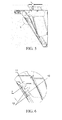
FIG. 4 is another schematic structural view of a filter plate and a fume collecting hood before being connected in a range hood according to an embodiment of the present invention; -
FIG. 5 is a sectional view of a filter plate and a fume collecting hood after being connected in a range hood according to an embodiment of the present invention; -
FIG. 6 is a partial enlarged view at position C inFIG. 5 ; -
FIG. 7 is a schematic structural view of a magnetic attraction portion assembled on a fume collecting hood in a range hood according to an embodiment of the present invention; -
FIG. 8 is a partial enlarged view at position B inFIG. 7 ; -
FIG. 9 is a schematic structural view of a magnetic attraction portion in a range hood according to an embodiment of the present invention; -
FIG. 10 is another schematic structural view of a magnetic attraction portion in a range hood according to an embodiment of the present invention; and -
FIG. 11 is still another schematic structural view of a magnetic attraction portion in a range hood according to an embodiment of the present invention. - 1: filter plate, 2: fume collecting hood, 3: hook portion, 4: support portion, 5: magnetic attraction portion, 6: connection portion, 7: shaft lever portion, 8: block portion, 9: stop portion, 10: guide rail portion, 11: hook, 12: handle portion, 13: cylindrical portion, 14: first bump, 15: block ring, 16: second bump, 17: first through hole, 18: second through hole, 19: through hole portion, 20: range hood.
- In order to make the objectives, solutions and beneficial effects of the present invention clearer, the present invention is further described below with reference to the accompanying drawings and exemplary embodiments.
- As shown in
FIG. 1 to FIG. 11 , the present invention provides a side suction range hood in an embodiment, which includes afilter plate 1 and afume collecting hood 2. A fume inlet hole is opened on thefume collecting hood 2. A fume inlet passage is formed by an interval between thefilter plate 1 and thefume collecting hood 2. The fume flows to a fan system after passing through the fume inlet passage and the fume inlet hole in sequence. The range hood also includes two first connection devices and two second connection devices. The first connection devices and the second connection device are used together to connect thefilter plate 1 and thefume collecting hood 2, thereby forming the fume inlet passage. Each first connection device includes ahook portion 3 and asupport portion 4. In a use state (that is, when thefilter plate 1 and thefume collecting hood 2 are connected, same below), thehook portion 3 is clamped on thesupport portion 4. Each second connection device includes amagnetic attraction portion 5. The two second connection devices connect thefilter plate 1 and thefume collecting hood 2 through a magnetic attraction force generated by themagnetic attraction portion 5. - As shown in
FIG. 1 ,FIG. 3 ,FIG. 4 ,FIG. 5 , andFIG. 7 , thehook portion 3 is disposed on thefilter plate 1, thesupport portion 4 is disposed on thefume collecting hood 2, themagnetic attraction portion 5 is disposed on thefume collecting hood 2, and thefilter plate 1 is made of a stainless steel material. The number of the first connection devices is two. Each first connection device includes ahook portion 3 and asupport portion 4. As shown in the drawings, the twosupport portions 4 are symmetrically disposed at an upper portion of thefume collecting hood 2, and the twohook portions 3 are symmetrically disposed at an upper portion of thefilter plate 1. The number of the second connection devices is also two. Each second connection device includes amagnetic attraction portion 5. As shown in the drawings, the twomagnetic attraction portions 5 are symmetrically disposed at a lower portion of thefume collecting hood 2. - As shown in
FIG. 1, FIG. 2 ,FIG. 4 ,FIG. 5, FIG. 6 andFIG. 7 , thesupport portion 4 includes aconnection portion 6, ashaft lever portion 7 and ablock portion 8 disposed in sequence, and theconnection portion 6 is connected to thefume collecting hood 2. Thehook portion 3 includes ahook 11. In a use state, thehook 11 is clamped on theshaft lever portion 7. Thesupport portion 4 further includes astop portion 9. Thestop portion 9 is connected to theconnection portion 6. Thestop portion 9 is used to prevent thefilter plate 1 or thehook portion 3 from touching thefume collecting hood 2 when the hook 11 I rotates around theshaft lever portion 7. In addition, thesupport portion 4 further includes aguide rail portion 10. Theguide rail portion 10 is connected to theconnection portion 6. Accordingly, thehook portion 3 further includes ahandle portion 12, as shown inFIG. 3 ,FIG. 5 and FIG. 6 . When thehook 11 rotates around theshaft lever portion 7 to move thefilter plate 1 towards themagnetic attraction portion 5, thehandle portion 12 is clamped in theguide rail portion 10 and moves along theguide rail portion 10, so that thehook 11 moves along an axial direction of theshaft lever portion 7. When thefilter plate 1 touches themagnetic attraction portion 5, that is, thefilter plate 1 and thefume collecting hood 2 are connected, thefilter plate 1 is in a stable state. The "filter plate 1 being in a stable state" refers to that thefilter plate 1 and thefume collecting hood 2 are firmly fixed together, and when the range hood is started and in a use state, thefilter plate 1 does not shake relative to thefume collecting hood 2. In this embodiment, when thefilter plate 1 and themagnetic attraction portion 5 are connected, thehook 11 is held against theconnection portion 6, and thehandle portion 12 is also held against theconnection portion 6. Moreover, theguide rail portion 10 is inclined relative to thehandle portion 12, and therefore "thefilter plate 1 is in a stable state". In fact, since theguide rail portion 10 is inclined relative to thehandle portion 12, the above stable state can be achieved as long as one of thehook 11 and thehandle portion 12 is held against theconnection portion 6. - As shown in
FIG. 1 ,FIG. 4 ,FIG. 5 andFIG. 7 toFIG. 11 , themagnetic attraction portion 5 is clamped on thefume collecting hood 2. Themagnetic attraction portion 5 includes acylindrical portion 13, and afirst bump 14 and ablock ring 15 disposed on thecylindrical portion 13. A distance between thefirst bump 14 and theblock ring 15 is slightly greater than the thickness of thefume collecting hood 2. Asecond bump 16 is disposed on theblock ring 15 in a direction towards thefirst bump 14. Specifically, thesecond bump 16 and thefirst bump 14 are disposed in a way that the two are not opposite each other. A first throughhole 17 and a second throughhole 18 are opened on thefume collecting hood 2. The second throughhole 18 is opened at the edge of the first throughhole 17, that is, the second throughhole 18 is in communication with the first throughhole 17. The first throughhole 17 is for thecylindrical portion 13 to pass through, and the second throughhole 18 is for thefirst bump 14 to pass through. After thecylindrical portion 13 and thefirst bump 14 pass through the first throughhole 17 and the second throughhole 18, respectively, theblock ring 15 is closely attached on an external wall of the fume collecting hood 2 (namely, the wall of thefume collecting hood 2 towards the filter plate 1). At this time, thecylindrical portion 13 is rotated, and thesecond bump 16 is clamped in the second throughhole 18, thereby fixing themagnetic attraction portion 5 on thefume collecting hood 2. The number of the second throughholes 18 and the number of thefirst bumps 14 are the same, and both are three or more. The number of thesecond bump 16 is one. Thecylindrical portion 13 uses a hollow structure, and a magnet is disposed therein.FIG. 9 andFIG. 10 are schematic structural views when the magnet is not disposed. A throughhole portion 19 is formed by an interval between theblock ring 15 and thecylindrical portion 13. Thesecond bump 16 is disposed at a position near the throughhole portion 19. - All components of the
hook portion 3 are integrally formed, and all components of thesupport portion 4 are also integrally formed, which improves the manufacturing efficiency and reduces the manufacturing cost. - The above embodiments are merely preferred embodiments of the present invention, and other embodiments can be obtained by modifying and replacing some technical features. For example, the hook portion may also be disposed on the fume collecting hood, and the support portion may also be disposed on the filter plate. Further, the magnetic attraction portion may also be disposed on the filter plate. Further, the number of the first connection device(s) may be one, three or more. Further, the number of the second connection device(s) may be one, three or more. Further, the filter plate may also be disposed with an attracted portion, and the position of the attracted portion corresponds to the magnetic attraction portion on the fume collecting hood. The attracted portion is made of a material attractable by a magnet, and the parts of the filter plate other than the attracted portion may be made of other materials. Further, the technical solution of the present invention may also be applied to a top suction range hood. Further, the distance between the first bump and the block ring may be equal to the thickness of the fume collecting hood. At this time, the first bump, the block ring and the second bump are all made of a material with certain elasticity. Further, the number of the second through hole(s) and the first bump(s) may also be one, two, four or more.
- It should be noted that the present invention shall not be construed as being limited to the implementation manners described above, and instead shall be construed as covering all possible implementation situations determined by the claims in combination with the contents disclosed in the specification of the present invention. Therefore, any simple variation, equivalent change or modification made to the above embodiments without departing from the contents of the technical solution of the present invention and according to the technical substance of the present invention shall fall within the protection scope of the technical solutions of the present invention.
Claims (15)
- A range hood (20), comprising a filter plate (1), a fume collecting hood (2), wherein the collecting hood (2) has a fume inlet hole, and a fume inlet passage is formed by an interval between the filter plate (1) and the fume collecting hood (2), further comprising
a first connection device and a second connection device, wherein the first connection device and the second connection device are implemented to couple the filter plate (1) with the fume collecting hood (2);
the first connection device comprises a hook portion (3) and a support portion (4), and in a use state, the hook portion (3) is clamped on the support portion (4); and
the second connection device comprises a magnetic attraction portion (5), and the second connection device is implemented to couple the filter plate (1) with the fume collecting hood (2) through a magnetic attraction force generated by the magnetic attraction portion (5). - The range hood (20) according to claim 1, characterized in that: the hook portion (3) is disposed on the filter plate (1); and the support portion (4) is disposed on the fume collecting hood (2).
- The range hood (20) according to claim 1 or 2, characterized in that: the magnetic attraction portion (5) is disposed on the fume collecting hood (2); and the filter plate (1) is at least partly made of a material attractable by a magnet.
- The range hood (20) according to any one of claims 1-3, characterized in that: the number of the first connection devices is two; and the number of the second connection devices is two.
- The range hood (20) according to any one of claims 1 - 4, characterized in that: the support portion (4) comprises a connection portion (6), a shaft lever portion (7) and a block portion (8) disposed in sequence; the connection portion (6) is connected to the fume collecting hood (2); and the hook portion (3) comprises a hook (11) implemented to clamp on the shaft lever portion (7).
- The range hood (20) according to claim 5, characterized in that: the support portion (4) further comprises a stop portion (9); the stop portion (9) is implemented to prevent the filter plate (1) or the hook portion (3) from touching the fume collecting hood (2) when the hook portion (3) rotates around the shaft lever portion (7).
- The range hood (20) according to claim 6, characterized in that: the stop portion (9) is connected to the connection portion (6).
- The range hood (20) according to claim 5 or 6, characterized in that: the support portion (4) further comprises a guide rail portion (10); the hook portion (3) further comprises a handle portion (12); and the range hood (20) is implemented such that when the hook portion (3) rotates around the shaft lever portion (7) to move the filter plate (1) towards the fume collecting hood (2), the handle portion (12) moves along the guide rail portion (10), so that the hook (11) moves along an axial direction of the shaft lever portion (7); and when the filter plate (1) and the fume collecting hood (2) are connected, the filter plate (1) is in a stable state.
- The range hood (20) according to claim 8, characterized in that: the guide rail portion (10) is connected to the connection portion (6).
- The range hood (20) according to any one of claims 1 - 9, characterized in that: the magnetic attraction portion (5) is disposed on the fume collecting hood (2); an attracted portion is disposed on the filter plate (1); and the position of the attracted portion corresponds to the magnetic attraction portion (5), and the attracted portion is at lest partly made of a material attractable by a magnet.
- The range hood (20) according to any one of claims 1 to 10, characterized in that:the magnetic attraction portion (5) is clamped on the fume collecting hood (2);the magnetic attraction portion (5) comprises a cylindrical portion (13) and a first bump (14) and a block ring (15) disposed on the cylindrical portion (13), wherein a distance between the first bump (14) and the block ring (15) is equal to or greater than the thickness of the fume collecting hood (2), and a second bump (16) is disposed on the block ring (15) in a direction towards the first bump (14);the fume collecting hood (2) comprises a first through hole (17) and a second through hole (18), the second through hole (18) being located at the edge of the first through hole (17), the first through hole (17) being implemented such that the cylindrical portion (13) passes through, and the second through hole (18) being implemented such that the first bump (14) passes through; and the cylindrical portion (13) and the first bump (14) being passed through the first through hole (17) and the second through hole (18), respectively, wherein the block ring (15) is closely attached on an external wall of the fume collecting hood (2) and the cylindrical portion (13) is rotated such that the second bump (18) is clamped in the second through hole (18), thereby fixing the magnetic attraction portion (5) on the fume collecting hood (2).
- The range hood (20) according to claim 11, characterized in that: the number of the second through holes (18) and the number of the first bumps (14) are the same, and both are 3 or more.
- The range hood (20) according to claim 11 or 12, characterized in that: the cylindrical portion (13) has a hollow structure, and a magnet is disposed inside the cylindrical portion (13).
- The range hood (20) according to any one of claims 11 - 13, characterized in that: a through hole portion (19) is formed by an interval between the block ring (15) and the cylindrical portion (13); and the second bump (16) is disposed at the position near the through hole portion (19).
- The range hood (20) according to any one of claims 1 to 14, characterized in that: the range hood (20) is a side suction range hood.
Applications Claiming Priority (1)
| Application Number | Priority Date | Filing Date | Title |
|---|---|---|---|
| CN201110201427.4A CN102878598B (en) | 2011-07-13 | 2011-07-13 | Smoke exhaust ventilator |
Publications (1)
| Publication Number | Publication Date |
|---|---|
| EP2546578A1 true EP2546578A1 (en) | 2013-01-16 |
Family
ID=46456423
Family Applications (1)
| Application Number | Title | Priority Date | Filing Date |
|---|---|---|---|
| EP12174883A Withdrawn EP2546578A1 (en) | 2011-07-13 | 2012-07-04 | Range hood |
Country Status (2)
| Country | Link |
|---|---|
| EP (1) | EP2546578A1 (en) |
| CN (1) | CN102878598B (en) |
Cited By (19)
| Publication number | Priority date | Publication date | Assignee | Title |
|---|---|---|---|---|
| JP2014202439A (en) * | 2013-04-08 | 2014-10-27 | 富士工業株式会社 | Range hood |
| EP2840323A3 (en) * | 2013-08-14 | 2015-10-14 | Whirlpool Corporation | System and method for mounting undercabinet ventilation hood |
| EP3106760A1 (en) * | 2015-06-15 | 2016-12-21 | Miele & Cie. KG | Filter device |
| EP3196556A1 (en) * | 2016-01-25 | 2017-07-26 | Miele & Cie. KG | Extractor hood |
| EP3222919A1 (en) * | 2016-03-23 | 2017-09-27 | BSH Hausgeräte GmbH | Extractor hood with viewing cover and inner element |
| CN107218636A (en) * | 2017-08-04 | 2017-09-29 | 合肥宁致信息技术有限公司 | A kind of smoke exhaust ventilator of convenient use |
| US9897330B2 (en) | 2013-05-29 | 2018-02-20 | Whirlpool Corporation | System and method for mounting undercabinet ventilation hood |
| US9897331B2 (en) | 2013-05-29 | 2018-02-20 | Whirlpool Corporation | System and method for mounting undercabinet ventilation hood |
| CN107975838A (en) * | 2017-05-26 | 2018-05-01 | 宁波方太厨具有限公司 | A kind of range hood with movable smoke deflector |
| CN109855131A (en) * | 2017-11-30 | 2019-06-07 | 宁波方太厨具有限公司 | A kind of closed top-sucking kitchen ventilator of air inlet and its control method |
| EP3524890A1 (en) * | 2017-12-15 | 2019-08-14 | Miele & Cie. KG | Recording device, fixing element, fixing system, extractor hood, filter and hood system |
| CN110207200A (en) * | 2018-05-30 | 2019-09-06 | 华帝股份有限公司 | Oil screen device for range hood and range hood |
| CN110864452A (en) * | 2018-08-27 | 2020-03-06 | 宁波方太厨具有限公司 | A kind of anti-downwind fume collecting hood for water heater |
| CN113685866A (en) * | 2021-08-10 | 2021-11-23 | 广东格兰仕集团有限公司 | Range hood, smoke stove linkage system and air inlet control method of range hood |
| CN113739237A (en) * | 2021-10-15 | 2021-12-03 | 杭州老板电器股份有限公司 | Ceiling type range hood |
| CN114110690A (en) * | 2021-11-17 | 2022-03-01 | 河南中管环境科技研究院 | Oil smoke catalytic decomposition processing apparatus |
| CN114353142A (en) * | 2022-01-07 | 2022-04-15 | 杭州老板电器股份有限公司 | Smoke collection assembly, range hood and control method of smoke collection assembly |
| USD952828S1 (en) | 2020-07-28 | 2022-05-24 | Whirlpool Corporation | Vent hood |
| US11428419B2 (en) | 2020-07-28 | 2022-08-30 | Whirlpool Corporation | Vent hood assembly |
Families Citing this family (4)
| Publication number | Priority date | Publication date | Assignee | Title |
|---|---|---|---|---|
| CN203203110U (en) * | 2013-03-07 | 2013-09-18 | 湖北酒总厨业有限公司 | Combined type oil smoke purification device and pre-filtration equalizing device |
| CN103644585B (en) * | 2013-11-29 | 2016-04-27 | 中山市日顺厨卫有限公司 | A kind of range hood convenient for cleaning |
| CN106468454B (en) * | 2015-08-20 | 2020-12-01 | 博西华电器(江苏)有限公司 | Side suction range hood |
| CN116465002A (en) * | 2022-01-11 | 2023-07-21 | 芜湖美的智能厨电制造有限公司 | Cabinet device of range hood |
Citations (3)
| Publication number | Priority date | Publication date | Assignee | Title |
|---|---|---|---|---|
| EP1607686A1 (en) * | 2004-06-16 | 2005-12-21 | SIFIM S.r.l. | Kitchen hood filter with safety means for retaining the filter on the hood |
| EP1621819A2 (en) * | 2004-07-27 | 2006-02-01 | Miele & Cie. KG | Smoke extracting hood |
| DE102004062684A1 (en) * | 2004-12-21 | 2006-06-22 | Langner, Manfred H. | Air extraction hood for domestic or industrial use has baseplate detachably fastened to underside of housing by magnetic fastening means, by clamping, or by lockable snap-on connection |
Family Cites Families (1)
| Publication number | Priority date | Publication date | Assignee | Title |
|---|---|---|---|---|
| CN201170627Y (en) * | 2008-01-24 | 2008-12-24 | 宁波市万茂电器有限公司 | Near suction type fume exhaustor |
-
2011
- 2011-07-13 CN CN201110201427.4A patent/CN102878598B/en not_active Expired - Fee Related
-
2012
- 2012-07-04 EP EP12174883A patent/EP2546578A1/en not_active Withdrawn
Patent Citations (3)
| Publication number | Priority date | Publication date | Assignee | Title |
|---|---|---|---|---|
| EP1607686A1 (en) * | 2004-06-16 | 2005-12-21 | SIFIM S.r.l. | Kitchen hood filter with safety means for retaining the filter on the hood |
| EP1621819A2 (en) * | 2004-07-27 | 2006-02-01 | Miele & Cie. KG | Smoke extracting hood |
| DE102004062684A1 (en) * | 2004-12-21 | 2006-06-22 | Langner, Manfred H. | Air extraction hood for domestic or industrial use has baseplate detachably fastened to underside of housing by magnetic fastening means, by clamping, or by lockable snap-on connection |
Cited By (30)
| Publication number | Priority date | Publication date | Assignee | Title |
|---|---|---|---|---|
| JP2014202439A (en) * | 2013-04-08 | 2014-10-27 | 富士工業株式会社 | Range hood |
| US10240801B2 (en) | 2013-05-29 | 2019-03-26 | Whirlpool Corporation | System and method for mounting undercabinet ventilation hood |
| US10782031B2 (en) | 2013-05-29 | 2020-09-22 | Whirlpool Corporation | System and method for mounting undercabinet ventilation hood |
| US9897330B2 (en) | 2013-05-29 | 2018-02-20 | Whirlpool Corporation | System and method for mounting undercabinet ventilation hood |
| US9897331B2 (en) | 2013-05-29 | 2018-02-20 | Whirlpool Corporation | System and method for mounting undercabinet ventilation hood |
| US10018365B2 (en) | 2013-05-29 | 2018-07-10 | Whirlpool Corporation | System and method for mounting undercabinet ventilation hood |
| EP2840323A3 (en) * | 2013-08-14 | 2015-10-14 | Whirlpool Corporation | System and method for mounting undercabinet ventilation hood |
| US9523507B2 (en) | 2013-08-14 | 2016-12-20 | Whirlpool Corporation | Method for mounting undercabinet ventilation hood |
| US10948200B2 (en) | 2013-08-14 | 2021-03-16 | Whirlpool Corporation | System for mounting undercabinet ventilation hood |
| US10317093B2 (en) | 2013-08-14 | 2019-06-11 | Whirlpool Corporation | System for mounting undercabinet ventilation hood |
| EP3106760A1 (en) * | 2015-06-15 | 2016-12-21 | Miele & Cie. KG | Filter device |
| EP3196556A1 (en) * | 2016-01-25 | 2017-07-26 | Miele & Cie. KG | Extractor hood |
| EP3222919A1 (en) * | 2016-03-23 | 2017-09-27 | BSH Hausgeräte GmbH | Extractor hood with viewing cover and inner element |
| EP3904772A1 (en) * | 2016-03-23 | 2021-11-03 | BSH Hausgeräte GmbH | Extractor hood with viewing cover and inner element |
| CN107975838A (en) * | 2017-05-26 | 2018-05-01 | 宁波方太厨具有限公司 | A kind of range hood with movable smoke deflector |
| CN107975838B (en) * | 2017-05-26 | 2024-02-20 | 宁波方太厨具有限公司 | Range hood with movable smoke guide plate |
| CN107218636A (en) * | 2017-08-04 | 2017-09-29 | 合肥宁致信息技术有限公司 | A kind of smoke exhaust ventilator of convenient use |
| CN109855131A (en) * | 2017-11-30 | 2019-06-07 | 宁波方太厨具有限公司 | A kind of closed top-sucking kitchen ventilator of air inlet and its control method |
| CN109855131B (en) * | 2017-11-30 | 2024-01-16 | 宁波方太厨具有限公司 | Top suction type range hood with closeable air inlet and control method thereof |
| EP3524890A1 (en) * | 2017-12-15 | 2019-08-14 | Miele & Cie. KG | Recording device, fixing element, fixing system, extractor hood, filter and hood system |
| CN110207200A (en) * | 2018-05-30 | 2019-09-06 | 华帝股份有限公司 | Oil screen device for range hood and range hood |
| CN110864452A (en) * | 2018-08-27 | 2020-03-06 | 宁波方太厨具有限公司 | A kind of anti-downwind fume collecting hood for water heater |
| USD952828S1 (en) | 2020-07-28 | 2022-05-24 | Whirlpool Corporation | Vent hood |
| US11428419B2 (en) | 2020-07-28 | 2022-08-30 | Whirlpool Corporation | Vent hood assembly |
| USD1011505S1 (en) | 2020-07-28 | 2024-01-16 | Whirlpool Corporation | Vent hood |
| CN113685866A (en) * | 2021-08-10 | 2021-11-23 | 广东格兰仕集团有限公司 | Range hood, smoke stove linkage system and air inlet control method of range hood |
| CN113739237A (en) * | 2021-10-15 | 2021-12-03 | 杭州老板电器股份有限公司 | Ceiling type range hood |
| CN114110690A (en) * | 2021-11-17 | 2022-03-01 | 河南中管环境科技研究院 | Oil smoke catalytic decomposition processing apparatus |
| CN114110690B (en) * | 2021-11-17 | 2024-04-05 | 河南中管环境科技研究院 | Lampblack catalytic decomposition processing apparatus |
| CN114353142A (en) * | 2022-01-07 | 2022-04-15 | 杭州老板电器股份有限公司 | Smoke collection assembly, range hood and control method of smoke collection assembly |
Also Published As
| Publication number | Publication date |
|---|---|
| CN102878598B (en) | 2016-05-11 |
| CN102878598A (en) | 2013-01-16 |
Similar Documents
| Publication | Publication Date | Title |
|---|---|---|
| EP2546578A1 (en) | Range hood | |
| CN110384988A (en) | Air cleaner | |
| AU2017281474B2 (en) | Insert for a downdraft extractor | |
| CN204329100U (en) | Range hood | |
| EP3775699B1 (en) | Enclosure for a cooking fume extraction hood | |
| CN113302432A (en) | Fume extractor and combined device for cooking bench | |
| JP5060255B2 (en) | Range food | |
| JP2011179691A (en) | Exhaust port cover mounting tool | |
| JP6535877B2 (en) | Range food | |
| CN203869121U (en) | Air deflector provided with quick release filter net | |
| JP5991856B2 (en) | Range hood fan | |
| KR20110005818U (en) | Suction grill installation structure of ceiling air conditioner | |
| CN106016407B (en) | Locking mechanism, screen mounting structure and kitchen ventilator for kitchen ventilator | |
| CN221424931U (en) | Desktop range hood | |
| JP2018519145A (en) | Multistage food filter | |
| CN207527655U (en) | A kind of range hood with oil groove sealing ring | |
| CN215295069U (en) | Smoke collecting hood structure and range hood | |
| CN110332133A (en) | Fan assembly and range hood | |
| JP6613445B2 (en) | Range food | |
| JP6263561B2 (en) | Range food | |
| JP2020500621A5 (en) | ||
| CN211659552U (en) | air purifier | |
| CN103322604B (en) | Range hood | |
| CN215259992U (en) | An oil filter for an integrated stove | |
| KR102149319B1 (en) | Grease Filter |
Legal Events
| Date | Code | Title | Description |
|---|---|---|---|
| PUAI | Public reference made under article 153(3) epc to a published international application that has entered the european phase |
Free format text: ORIGINAL CODE: 0009012 |
|
| AK | Designated contracting states |
Kind code of ref document: A1 Designated state(s): AL AT BE BG CH CY CZ DE DK EE ES FI FR GB GR HR HU IE IS IT LI LT LU LV MC MK MT NL NO PL PT RO RS SE SI SK SM TR |
|
| AX | Request for extension of the european patent |
Extension state: BA ME |
|
| 17P | Request for examination filed |
Effective date: 20130716 |
|
| RBV | Designated contracting states (corrected) |
Designated state(s): AL AT BE BG CH CY CZ DE DK EE ES FI FR GB GR HR HU IE IS IT LI LT LU LV MC MK MT NL NO PL PT RO RS SE SI SK SM TR |
|
| RAP1 | Party data changed (applicant data changed or rights of an application transferred) |
Owner name: BSH HAUSGERAETE GMBH |
|
| 17Q | First examination report despatched |
Effective date: 20170223 |
|
| GRAP | Despatch of communication of intention to grant a patent |
Free format text: ORIGINAL CODE: EPIDOSNIGR1 |
|
| INTG | Intention to grant announced |
Effective date: 20190717 |
|
| STAA | Information on the status of an ep patent application or granted ep patent |
Free format text: STATUS: THE APPLICATION IS DEEMED TO BE WITHDRAWN |
|
| 18D | Application deemed to be withdrawn |
Effective date: 20191128 |