EP2547185A2 - Schalter mit Schutzgehäuse und Verfahren zur Herstellung davon - Google Patents
Schalter mit Schutzgehäuse und Verfahren zur Herstellung davon Download PDFInfo
- Publication number
- EP2547185A2 EP2547185A2 EP20120175073 EP12175073A EP2547185A2 EP 2547185 A2 EP2547185 A2 EP 2547185A2 EP 20120175073 EP20120175073 EP 20120175073 EP 12175073 A EP12175073 A EP 12175073A EP 2547185 A2 EP2547185 A2 EP 2547185A2
- Authority
- EP
- European Patent Office
- Prior art keywords
- plastic
- housing
- protective housing
- cable bushing
- connecting cables
- Prior art date
- Legal status (The legal status is an assumption and is not a legal conclusion. Google has not performed a legal analysis and makes no representation as to the accuracy of the status listed.)
- Granted
Links
Images
Classifications
-
- H—ELECTRICITY
- H01—ELECTRIC ELEMENTS
- H01H—ELECTRIC SWITCHES; RELAYS; SELECTORS; EMERGENCY PROTECTIVE DEVICES
- H01H37/00—Thermally-actuated switches
- H01H37/02—Details
- H01H37/32—Thermally-sensitive members
- H01H37/52—Thermally-sensitive members actuated due to deflection of bimetallic element
- H01H37/54—Thermally-sensitive members actuated due to deflection of bimetallic element wherein the bimetallic element is inherently snap acting
- H01H37/5427—Thermally-sensitive members actuated due to deflection of bimetallic element wherein the bimetallic element is inherently snap acting encapsulated in sealed miniaturised housing
-
- H—ELECTRICITY
- H05—ELECTRIC TECHNIQUES NOT OTHERWISE PROVIDED FOR
- H05K—PRINTED CIRCUITS; CASINGS OR CONSTRUCTIONAL DETAILS OF ELECTRIC APPARATUS; MANUFACTURE OF ASSEMBLAGES OF ELECTRICAL COMPONENTS
- H05K5/00—Casings, cabinets or drawers for electric apparatus
- H05K5/06—Hermetically-sealed casings
- H05K5/069—Other details of the casing, e.g. wall structure, passage for a connector, a cable, a shaft
-
- Y—GENERAL TAGGING OF NEW TECHNOLOGICAL DEVELOPMENTS; GENERAL TAGGING OF CROSS-SECTIONAL TECHNOLOGIES SPANNING OVER SEVERAL SECTIONS OF THE IPC; TECHNICAL SUBJECTS COVERED BY FORMER USPC CROSS-REFERENCE ART COLLECTIONS [XRACs] AND DIGESTS
- Y10—TECHNICAL SUBJECTS COVERED BY FORMER USPC
- Y10T—TECHNICAL SUBJECTS COVERED BY FORMER US CLASSIFICATION
- Y10T29/00—Metal working
- Y10T29/49—Method of mechanical manufacture
- Y10T29/49002—Electrical device making
- Y10T29/49105—Switch making
Definitions
- the present invention relates to a method for surrounding an electrical component with a protective housing, at least two connection surfaces for the electrical connection of connecting cables being provided on the component, said connecting cables being provided with a flexible plastic sheath and being connected electrically with their first ends to the connection surfaces and protruding with their second ends through a cable bushing out of the protective housing.
- the present invention also relates to an electrical component with a protective housing, at least two connection surfaces for the electrical connection of connecting cables being provided on the component, said connecting cables being provided with a flexible plastic sheath and being connected electrically with their first end to the connection surfaces and protruding with their second end through a cable bushing out of the protective housing.
- the known component is a temperature-dependent switch, which, in a known manner, depending on its temperature, produces an electrically conductive connection between the two connection surfaces.
- Such temperature-dependent switches are used for being connected in series in the power supply circuit of an electrical appliance to be protected and at the same time for being coupled thermally to the electrical appliance to be protected.
- a temperature-dependent switching mechanism with a snap-action bimetallic disc and a snap-action spring disc which is supported with its edge on the housing lower part and bears, in the centre, a movable contact part which interacts with a fixed contact part on the cover part of the switch is provided.
- an electrically conductive connection between the cover part and the lower part is provided, with in each case one connection surface for the connection of connecting strand wires being provided on the cover part and the lower part.
- the snap-action bimetallic disc is enclosed loosely in the switching mechanism below its response temperature and is not involved in the current conduction. If the temperature now increases above the response temperature of the snap-action bimetallic disc, said snap-action bimetallic disc changes its configuration and in the process presses the movable contact part away from the stationary contact part, counter to the force of the snap-action spring disc, with the result that the switch is opened.
- the known switch can be provided with a so-called self-holding resistor, which is arranged electrically in parallel with the connection surfaces. If the temperature-dependent switch now opens at an excessively high temperature of the electrical appliance to be protected, a residual current flows through this self-holding resistor, which is preferably manufactured from a material with positive temperature coefficients.
- a temperature-dependent switch with a self-holding function is used in particular when frequent reconnection of the electrical appliance to be protected is undesired or results in damage, such as, for example, in the case of a mechanically jammed wash water pump, whose impeller first needs to be cleaned before the pump can start up again.
- Such a self-holding temperature-dependent switch is known from DE 37 10 672 A1 .
- the current to be guided through the temperature-dependent switch is in the range of several amperes, the current is conducted preferably no longer via the snap-action spring disc, but via a current transfer element, which is moved by the snap-action spring disc and interacts with two stationary contacts, which are arranged on the cover of the temperature-dependent switch.
- the operating current of the electrical appliance to be protected flows through this current transfer element.
- Such a temperature-dependent switch is known from DE 26 44 411 A1 or DE 197 08 436 A1 .
- This temperature-dependent switch can also be provided with a self-holding function, as is known, for example, from DE 197 27 197 A1 .
- Such current-dependent and temperature-dependent switches are known, for example, from DE 44 28 226 A1 and DE 197 48 589 A1 .
- DE 37 33 693 A1 proposes introducing the temperature-dependent switch into a metal housing which is then welded shut and using a compression-glass bushing as cable bushing, through which the connecting cables are passed out of the interior of the metal housing.
- DE 101 10 562 C1 has disclosed providing particular adhesive-bonding measures in order to seal the interface between the housing lower part and the housing upper part of a temperature-dependent switch.
- the object of the present invention to provide a component and a method of the type mentioned at the outset, in which the protective housing is sealed off hermetically from the outside, although connecting cables lead out of the interior of the protective housing towards the outside.
- the method should be simple and inexpensive to implement and the component part should have an inexpensive design.
- the connecting cables are provided with an additional sheathing, which is by firm bond materially connected to the plastic sheath, between the first and second ends of said connecting cables over a first length,
- the component is then provided with the protective housing and the cable bushing, the cable bushing manufactured from plastic being by firm bond materially connected to the additional sheathing over a second length.
- this object is achieved according to the invention by the fact that an additional sheathing is arranged on the plastic sheath over a first length and is by firm bond materially connected to the plastic sheath, and that the cable bushing is manufactured from plastic and is by firm bond materially connected to the additional sheathing over a second length.
- connecting cables are provided with the additional sheathing before they are soldered or welded to the connection surfaces.
- the plastic material of the additional sheathing can in this case be designed and processed in such a way that, when it is subsequently connected to the cable bushing, which consists of plastic, a firmly bonded connection is likewise produced between the cable bushing and the additional sheathing.
- the electrical component is a temperature-dependent switch, which, depending on its temperature, produces an electrically conductive connection between the two connection surfaces, the switch having a housing, on which the connection surfaces are provided.
- the method according to the invention can also be used for sheathing or protecting any desired electrical component having at least two external terminals, said method has particular advantages when the component is the mentioned temperature-dependent switch.
- this temperature-dependent switch it is firstly extremely difficult to seal off its "dedicated" housing, on which the two connection surfaces are provided, to a sufficient extent. That is to say that when sealing off the housing of the temperature-dependent switch, care always needs to be taken as regards the pressure, heat and outgassing of the sealing materials that the sensitive snap-action bimetallic disc and the likewise sensitive snap-action spring disc are not damaged or attacked.
- the protective housing is manufactured in one piece from plastic and the cable bushing is formed integrally with the protective housing, for which purpose the protective housing and the cable bushing are preferably produced by a plastic being cast or injection-moulded around the component.
- the cable bushing is an integral part of the protective housing, with the result that, apart from the interfaces between the cable bushing and the additional sheathing and between the additional sheathing and the connecting cables, there are no further interfaces along which gases or liquids could diffuse into the interior of the protective housing.
- the firmly bonded material connection between the cable bushing and the additional sheathing can be brought about by temperature or pressure and/or by virtue of the fact that the additional sheathing has not yet been polymerized out to a sufficient extent during casting of the protective housing, with the result that the firmly onded connection between the plastic of the protective housing and the plastic of the additional sheathing is produced without any problems.
- the material of the additional sheathing can be selected such that it is compatible with the plastic sheath of the connecting cables on its inside and with the material of the cable bushing on its outside.
- the material of the additional sheathing can be selected, for example, for a concentration gradient for the plastic composition to be provided in the sheathing.
- the component may also be made for the component to be introduced into the interior of an enveloping housing in such a way that the connecting cables protrude with their second end out of the enveloping housing and that thereafter the cable bushing is formed, preferably the interior of the enveloping housing being at least partially filled with a plastic, which in the process forms the cable bushing.
- the enveloping housing can be a single-part or else two-part enveloping housing comprising an upper form and a lower form, into which the component is introduced before the upper form is placed on top.
- the enveloping housing can remain on the protective housing in order to impart a particular mechanical stability to the protective housing or in order to ensure a good thermal connection to the electrical appliance to be protected.
- the additional sheathing is by firm bond materially connected to the plastic sheath by adhesive-bonding, welding or vulcanisation, wherein, alternatively, the additional sheathing can also be injection-moulded or cast around the plastic sheath. Finally, it is alternatively possible to press the additional sheathing onto the plastic sheath. With all of these measures, suitable temperatures and pressures can be used.
- the suitable measures can be used, depending on the material of the plastic sheath and the material of the protective housing which is yet to be produced subsequently, in order to apply a plastic material which is suitable for subsequent further-processing as sheathing on the plastic sheath in a firmly bonded manner.
- thermoplastic materials or reactive resins can be used which enter into a firmly bonded material connection with the respective material of the plastic sheath.
- the surfaces of the plastic sheath or later the surface of the additional sheathing can be activated mechanically or chemically before the firmly bonded connection is produced.
- plastic material of the plastic sheath tends to be flexible, while the plastic material of the protective sleeve tends to be stiff and rigid, with the result that the additional sheathing can produce compensation between the flexible material of the connecting cable and the rigid material of the protective housing, which provides further advantages.
- the additional sheathing extends between the first and second ends of the connecting cable over a first length, which is substantially shorter than the length of the connecting cable itself; it is no more than 10% of the length thereof, for example.
- the second length over which the additional sheathing is by firm bond materially connected to the cable bushing corresponds virtually to the length of the first length, but is slightly shorter, with the result that the additional sheathing protrudes out of the protective housing with preferably 10% of its length.
- a firmly or materially bonded connection is understood to mean a firmly bonded material connection which is formed over the corresponding length and the entire circumference, with this quite possibly meaning that in the central region of the connecting length this firmly bonded connection is not formed completely, but is rather present at the outer regions of the length.
- the firmly bonded connection is always provided completely in the circumferential direction over the respective length sections, with the result that the interior of the protective sleeve is sealed off from the outside world in diffusion-tight fashion.
- the diameter of the additional sheathing is at least slightly larger than the diameter of the connecting cable.
- the thickness of the additional sheathing in the diameter direction is substantially dependent on the selection of materials, but the diameter of the additional sheathing is generally no greater than three times the diameter of the connecting cable.
- the material of the additional sheathing is essentially selected such that this "outer" firmly bonded connection can be produced relatively easily and without any damage to the electrical component.
- the connecting cable as a cable run from a cable drum and guide it through a corresponding plastic injection-moulding or casting apparatus, in which the surface of the plastic sheath is first pretreated and is then provided with the additional sheathing. Then, the connecting cable is cut to the desired length and the insulation is stripped at least from its first end, but generally from both of its ends.
- the component in particular the temperature-dependent switch
- the connecting cables can be completely prefabricated with its housing and the two connection surfaces, with the type and length of the connecting cables only being selected later and depending on the application, then the connecting cables are first provided with the additional sheathing and are brought to length and are then electrically connected to the components and finally surrounded by the protective housing.
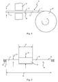
- Fig. 1 10 denotes a cable drum, on which a continuous cable 11 has been wound.
- the continuous cable 11 is drawn through an apparatus 12, in which it is mechanically and/or chemically activated or modified and then provided with an additional sheathing consisting of plastic, as is shown in Figure 2 .
- the continuous cable 11 is drawn by its first end 14 through the apparatus 12, with a second end 15 still being connected to the continuous cable 11 at a cutting point 16.
- the first end 14 is located on a separating apparatus 17, which is used also to sever the second end 15 at the cutting point 16 once the continuous cable has been drawn further through the apparatus 12.
- the continuous cable 11 has been provided with a plastic sheath 18, which has a surface 19, which is mechanically or chemically activated or modified in a suitable manner in the apparatus 12 before the additional sheathing is applied.
- Figure 2 shows a connecting cable 21 which has been cut to a corresponding length, in which a strand wire, denoted by 22, is protected by the plastic sheath 18.
- the connecting cable 21 has a diameter 23 and a length 24, which are both selected depending on the desired application.
- the connecting cable 21 is now provided with an additional sheathing 25 consisting of plastic, which has a diameter 26 and a length 27.
- the length 27 is markedly shorter than the length 24, and is generally at most 10% of the length 24.
- the diameter 26 is at least slightly larger than the diameter 23; in general it is at most from two times to three times the size of the diameter 23.
- the additional sheathing 25 was applied to the surface 19 in such a way that the material of the sheathing 25 entered into a firmly bonded material connection with the material of the plastic sheath 18.
- the additional sheathing 25 can be by firm bond materially connected to the plastic sheath 18 by adhesive-bonding, welding or vulcanisation, with it also being possible for the additional sheathing to be injection-moulded or cast around the plastic sheath 18 or for the additional sheathing to be pressed onto the plastic sheath 18 under pressure and elevated temperature.
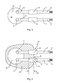
- connecting cables 21 Once the connecting cables 21 have been produced correspondingly, they are connected to a component 28, as is illustrated in Figure 3 .
- the component 28 is preferably a temperature-dependent switch, which has a housing 29, on which two connection surfaces 31 are provided, to which the connecting cables 21 have been soldered or welded with their inner ends 14.
- the component 28 which has been prefabricated with connecting cables 21 as shown in Figure 3 i.e. the correspondingly prefabricated temperature-dependent switch, is now surrounded by a protective housing 32, as is illustrated in Figure 4 .
- This protective housing 32 consists of a plastic, which was used for injection-moulding or casting around the component part 28 up to over half the length 27 of the additional sheathing 25.
- a cable bushing 33 is produced integrally and in one piece with the protective housing 32, said cable bushing lying circumferentially around the additional sheathings 25 and likewise being by firm bond materially connected thereto.
- the surfaces 34 of the additional sheathing 25 can also be treated mechanically or chemically, i.e. activated or modified, in order to ensure a secure material connection to the surface 34.
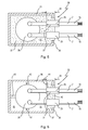
- the component 28 shown in Figure 3 it is also possible for the component 28 shown in Figure 3 to be introduced into the interior 35 of an enveloping housing 36 and for the interior 35 then to be completely or partly filled with a plastic 37 in such a way that the cable bushings 33 again form around the additional sheathings 25.
- This embodiment is shown in Figure 5 .
- a flange 38 ensures that the plastic 37 is held in the enveloping housing 36.
- the flange 38 can be removed and the protective housing formed by the plastic material 37 removed out of the enveloping housing 36.
- Figure 4 and Figure 5 also show that the material connection between the cable bushing 33 and the sheathing 25 is produced over a second length 39, which corresponds to markedly more than half the length 27 of the sheathing 25.
- the sheathing 25 protrudes out of the cable bushing 33 only by 10% of its length 27.
- connection between the cover 40 and the enveloping housing 36 is curved and can be made strong and long enough for protecting the space 42 and preventing dust and moisture entering into the space 42.
- the component part 28 may be oriented and hold within the enveloping housing 36 by struts 43. Despite the struts 43, the confinement line 41 and the free space 42, the embodiment of Fig. 6 corresponds to that of Fig. 5 .
Landscapes
- Physics & Mathematics (AREA)
- Thermal Sciences (AREA)
- Engineering & Computer Science (AREA)
- Microelectronics & Electronic Packaging (AREA)
- Connector Housings Or Holding Contact Members (AREA)
- Cable Accessories (AREA)
- Insulating Bodies (AREA)
Applications Claiming Priority (1)
| Application Number | Priority Date | Filing Date | Title |
|---|---|---|---|
| DE102011107110A DE102011107110B4 (de) | 2011-07-12 | 2011-07-12 | Verfahren zum Umgeben eines elektrischen Bauteils mit einem Schutzgehäuse sowie elektrisches Bauteil mit einem Schutzgehäuse |
Publications (3)
| Publication Number | Publication Date |
|---|---|
| EP2547185A2 true EP2547185A2 (de) | 2013-01-16 |
| EP2547185A3 EP2547185A3 (de) | 2015-03-04 |
| EP2547185B1 EP2547185B1 (de) | 2016-08-31 |
Family
ID=46754244
Family Applications (1)
| Application Number | Title | Priority Date | Filing Date |
|---|---|---|---|
| EP12175073.1A Active EP2547185B1 (de) | 2011-07-12 | 2012-07-05 | Schalter mit Schutzgehäuse und Verfahren zur Herstellung davon |
Country Status (6)
| Country | Link |
|---|---|
| US (1) | US8642901B2 (de) |
| EP (1) | EP2547185B1 (de) |
| CN (1) | CN102883572B (de) |
| DE (1) | DE102011107110B4 (de) |
| DK (1) | DK2547185T3 (de) |
| ES (1) | ES2604503T3 (de) |
Families Citing this family (7)
| Publication number | Priority date | Publication date | Assignee | Title |
|---|---|---|---|---|
| DE102013215365A1 (de) * | 2013-08-05 | 2015-02-05 | Zf Friedrichshafen Ag | Elektrische Getriebesteuervorrichtung und Herstellungsverfahren |
| DE202014104730U1 (de) * | 2014-10-01 | 2016-01-07 | Tridonic Gmbh & Co Kg | Elektronisches Gerätegehäuse mit Vergussmasse-Verschluss |
| EP3002828B1 (de) * | 2014-10-03 | 2018-02-14 | Nexans | Anordnung und Verfahren zum abdichten der Verbindungsstelle von elektrischen Leitungen |
| JP2017157760A (ja) * | 2016-03-03 | 2017-09-07 | オムロン株式会社 | 光学電子機器 |
| DE102017215245A1 (de) * | 2017-08-31 | 2019-02-28 | Seg Automotive Germany Gmbh | Baueinheit mit einem Gehäuse |
| DE102018111712A1 (de) * | 2018-05-16 | 2019-11-21 | Kolektor Group D.O.O. | Elektro-Bauteil und Verfahren zu dessen Herstellung |
| JP6997685B2 (ja) * | 2018-07-31 | 2022-01-18 | ボーンズ株式会社 | 電流遮断装置、安全回路及び2次電池パック |
Citations (11)
| Publication number | Priority date | Publication date | Assignee | Title |
|---|---|---|---|---|
| DE2121802A1 (de) | 1971-05-03 | 1973-01-25 | Thermik Geraetebau Gmbh | Temperaturwaechter |
| DE2644411A1 (de) | 1976-10-01 | 1978-04-06 | Hofsass P | Temperaturwaechter |
| DE3733693A1 (de) | 1986-10-28 | 1988-05-11 | Hofsass P | Gekapselter temperaturschalter |
| DE3710672A1 (de) | 1987-03-31 | 1988-10-13 | Hofsass P | Temperaturwaechter mit einem gehaeuse |
| DE4428226C1 (de) | 1994-08-10 | 1995-10-12 | Thermik Geraetebau Gmbh | Temperaturwächter |
| DE19603310A1 (de) | 1996-01-31 | 1997-08-07 | Siemens Ag | Verfahren zur Bestimmung der Restlebensdauer von Kontakten in Schaltgeräten und zugehörige Anordnung |
| DE19708436A1 (de) | 1997-03-01 | 1998-09-10 | Marcel Hofsaes | Temperaturabhängiger Schalter mit Kontaktbrücke |
| DE19727197A1 (de) | 1997-06-26 | 1999-02-04 | Marcel Hofsaess | Temperaturabhängiger Schalter mit Kontaktbrücke |
| DE19754158A1 (de) | 1997-10-28 | 1999-05-12 | Marcel Hofsaes | Verfahren zum Isolieren eines elektrischen Bauteiles |
| DE19748589A1 (de) | 1997-11-04 | 1999-05-20 | Marcel Hofsaes | Schalter mit einem temperaturabhängigen Schaltwerk |
| DE10110562C1 (de) | 2001-03-06 | 2002-12-19 | Marcel Hofsaes | Temperaturabhängiger Schalter mit aufgestempelter Kleberschicht |
Family Cites Families (15)
| Publication number | Priority date | Publication date | Assignee | Title |
|---|---|---|---|---|
| DE2759251B2 (de) * | 1977-12-31 | 1981-04-23 | Behr-Thomson Dehnstoffregler Gmbh, 7014 Kornwestheim | Zweistufen-Temperaturschalter |
| US4275432A (en) * | 1978-02-16 | 1981-06-23 | Tii Corporation | Thermal switch short circuiting device for arrester systems |
| FR2487569A1 (fr) * | 1980-07-24 | 1982-01-29 | Marchal Equip Auto | Dispositif assurant une traversee de fils electriques a travers une paroi en matiere plastique et boite ou carter comportant un tel dispositif |
| DE4337141C2 (de) * | 1993-10-30 | 1996-06-05 | Hofsaes Geb Zeitz Ulrika | Temperaturabhängiger Schalter |
| DE19509656C2 (de) * | 1995-03-17 | 1997-01-16 | Radbruch Jens Dipl Ing | Temperaturschutzschalter |
| CA2186828A1 (en) * | 1995-10-03 | 1997-04-04 | Robert W. Jorgensen | Universal cable clamp |
| DE19609577C2 (de) * | 1996-03-12 | 1998-02-19 | Thermik Geraetebau Gmbh | Schalter mit einem temperaturabhängigen Schaltwerk |
| DE19705154C2 (de) * | 1997-02-11 | 1999-06-02 | Thermik Geraetebau Gmbh | Temperaturabhängiger Schalter mit einem Bimetall-Schaltwerk |
| DE10121776B4 (de) * | 2001-05-04 | 2006-10-19 | Sick Ag | Sensor |
| US7146721B2 (en) * | 2004-03-15 | 2006-12-12 | Delphi Technologies, Inc. | Method of manufacturing a sealed electronic module |
| US7253362B1 (en) * | 2006-06-07 | 2007-08-07 | 3M Innovative Properties Company | Closure with wrapped cable |
| JP2008182119A (ja) * | 2007-01-25 | 2008-08-07 | Denso Corp | ホットメルト防水構造 |
| DE202009014202U1 (de) * | 2009-09-29 | 2009-12-24 | Schmidt, Frank | Temperaturschalter |
| CN101894707B (zh) * | 2010-07-19 | 2012-10-10 | 桂林航天电子有限公司 | 电机温度继电器 |
| DE102011101862B4 (de) * | 2011-05-12 | 2012-12-13 | Thermik Gerätebau GmbH | Temperaturabhängiger Schalter mit Stromübertragungsglied |
-
2011
- 2011-07-12 DE DE102011107110A patent/DE102011107110B4/de not_active Expired - Fee Related
-
2012
- 2012-07-05 DK DK12175073.1T patent/DK2547185T3/en active
- 2012-07-05 ES ES12175073.1T patent/ES2604503T3/es active Active
- 2012-07-05 EP EP12175073.1A patent/EP2547185B1/de active Active
- 2012-07-12 CN CN201210241866.2A patent/CN102883572B/zh active Active
- 2012-07-12 US US13/547,341 patent/US8642901B2/en active Active
Patent Citations (11)
| Publication number | Priority date | Publication date | Assignee | Title |
|---|---|---|---|---|
| DE2121802A1 (de) | 1971-05-03 | 1973-01-25 | Thermik Geraetebau Gmbh | Temperaturwaechter |
| DE2644411A1 (de) | 1976-10-01 | 1978-04-06 | Hofsass P | Temperaturwaechter |
| DE3733693A1 (de) | 1986-10-28 | 1988-05-11 | Hofsass P | Gekapselter temperaturschalter |
| DE3710672A1 (de) | 1987-03-31 | 1988-10-13 | Hofsass P | Temperaturwaechter mit einem gehaeuse |
| DE4428226C1 (de) | 1994-08-10 | 1995-10-12 | Thermik Geraetebau Gmbh | Temperaturwächter |
| DE19603310A1 (de) | 1996-01-31 | 1997-08-07 | Siemens Ag | Verfahren zur Bestimmung der Restlebensdauer von Kontakten in Schaltgeräten und zugehörige Anordnung |
| DE19708436A1 (de) | 1997-03-01 | 1998-09-10 | Marcel Hofsaes | Temperaturabhängiger Schalter mit Kontaktbrücke |
| DE19727197A1 (de) | 1997-06-26 | 1999-02-04 | Marcel Hofsaess | Temperaturabhängiger Schalter mit Kontaktbrücke |
| DE19754158A1 (de) | 1997-10-28 | 1999-05-12 | Marcel Hofsaes | Verfahren zum Isolieren eines elektrischen Bauteiles |
| DE19748589A1 (de) | 1997-11-04 | 1999-05-20 | Marcel Hofsaes | Schalter mit einem temperaturabhängigen Schaltwerk |
| DE10110562C1 (de) | 2001-03-06 | 2002-12-19 | Marcel Hofsaes | Temperaturabhängiger Schalter mit aufgestempelter Kleberschicht |
Also Published As
| Publication number | Publication date |
|---|---|
| DK2547185T3 (en) | 2016-12-19 |
| EP2547185B1 (de) | 2016-08-31 |
| US20130014987A1 (en) | 2013-01-17 |
| EP2547185A3 (de) | 2015-03-04 |
| DE102011107110A1 (de) | 2013-01-17 |
| CN102883572A (zh) | 2013-01-16 |
| US8642901B2 (en) | 2014-02-04 |
| DE102011107110B4 (de) | 2013-04-18 |
| ES2604503T3 (es) | 2017-03-07 |
| CN102883572B (zh) | 2015-07-01 |
Similar Documents
| Publication | Publication Date | Title |
|---|---|---|
| US8642901B2 (en) | Switch having a protective housing and method for producing same | |
| EP2299465B1 (de) | Temperaturabhängiger Schalter | |
| CN104037017B (zh) | 具有绝缘片的温控开关 | |
| JP4312350B2 (ja) | サーマルプロテクタ | |
| JP5878530B2 (ja) | 温度スイッチ | |
| CN109792141A (zh) | 用于密封导线束的组件和方法 | |
| CN103377850B (zh) | 温控开关 | |
| CN103871777A (zh) | 温度依赖型开关 | |
| JP4377135B2 (ja) | 温度センサ | |
| CN112542349B (zh) | 温控开关 | |
| JP6755508B2 (ja) | 感温ペレット型温度ヒューズ | |
| CN111247613B (zh) | 热敏颗粒型温度熔断器 | |
| KR100924157B1 (ko) | 서모 프로텍터 및 그 제조 방법 | |
| EP3901598B1 (de) | Temperatursensor für rotierende elektrische maschine und verfahren zur herstellung davon | |
| CN121646822A (zh) | 温度限制装置 | |
| CA2800856C (en) | Armoured resistor with an end sealing element | |
| FR2827077A1 (fr) | Fusible a coupure integrale comportant un element polymere limiteur de courant chauffant une liaison thermofusible | |
| JP2017220386A (ja) | 感温ペレット型温度ヒューズ | |
| EP4280249A1 (de) | Schutzschaltergehäuse mit zweistufiger struktur | |
| US20230402204A1 (en) | Circuit breaker housing formed using injection molding with a reinforcement material on an outer surface | |
| JP2019149228A (ja) | コードスイッチの端末封止方法 | |
| JP2004034467A (ja) | 電気部品の封止構造体および封止方法 | |
| CN106992103A (zh) | 热断路器 | |
| JPS6128361Y2 (de) | ||
| JP2014026783A (ja) | 絶縁電線およびその止水方法 |
Legal Events
| Date | Code | Title | Description |
|---|---|---|---|
| PUAI | Public reference made under article 153(3) epc to a published international application that has entered the european phase |
Free format text: ORIGINAL CODE: 0009012 |
|
| AK | Designated contracting states |
Kind code of ref document: A2 Designated state(s): AL AT BE BG CH CY CZ DE DK EE ES FI FR GB GR HR HU IE IS IT LI LT LU LV MC MK MT NL NO PL PT RO RS SE SI SK SM TR |
|
| AX | Request for extension of the european patent |
Extension state: BA ME |
|
| REG | Reference to a national code |
Ref country code: DE Ref legal event code: R079 Ref document number: 602012022325 Country of ref document: DE Free format text: PREVIOUS MAIN CLASS: H05K0005000000 Ipc: H05K0005060000 |
|
| PUAL | Search report despatched |
Free format text: ORIGINAL CODE: 0009013 |
|
| AK | Designated contracting states |
Kind code of ref document: A3 Designated state(s): AL AT BE BG CH CY CZ DE DK EE ES FI FR GB GR HR HU IE IS IT LI LT LU LV MC MK MT NL NO PL PT RO RS SE SI SK SM TR |
|
| AX | Request for extension of the european patent |
Extension state: BA ME |
|
| RIC1 | Information provided on ipc code assigned before grant |
Ipc: H05K 5/06 20060101AFI20150128BHEP Ipc: H01H 37/54 20060101ALI20150128BHEP |
|
| 17P | Request for examination filed |
Effective date: 20150820 |
|
| RBV | Designated contracting states (corrected) |
Designated state(s): AL AT BE BG CH CY CZ DE DK EE ES FI FR GB GR HR HU IE IS IT LI LT LU LV MC MK MT NL NO PL PT RO RS SE SI SK SM TR |
|
| GRAP | Despatch of communication of intention to grant a patent |
Free format text: ORIGINAL CODE: EPIDOSNIGR1 |
|
| INTG | Intention to grant announced |
Effective date: 20160307 |
|
| GRAS | Grant fee paid |
Free format text: ORIGINAL CODE: EPIDOSNIGR3 |
|
| GRAA | (expected) grant |
Free format text: ORIGINAL CODE: 0009210 |
|
| AK | Designated contracting states |
Kind code of ref document: B1 Designated state(s): AL AT BE BG CH CY CZ DE DK EE ES FI FR GB GR HR HU IE IS IT LI LT LU LV MC MK MT NL NO PL PT RO RS SE SI SK SM TR |
|
| REG | Reference to a national code |
Ref country code: CH Ref legal event code: EP Ref country code: GB Ref legal event code: FG4D |
|
| REG | Reference to a national code |
Ref country code: IE Ref legal event code: FG4D |
|
| REG | Reference to a national code |
Ref country code: DE Ref legal event code: R096 Ref document number: 602012022325 Country of ref document: DE |
|
| REG | Reference to a national code |
Ref country code: AT Ref legal event code: REF Ref document number: 825946 Country of ref document: AT Kind code of ref document: T Effective date: 20161015 |
|
| REG | Reference to a national code |
Ref country code: CH Ref legal event code: NV Representative=s name: RENTSCH PARTNER AG, CH Ref country code: NL Ref legal event code: FP |
|
| REG | Reference to a national code |
Ref country code: DK Ref legal event code: T3 Effective date: 20161215 |
|
| REG | Reference to a national code |
Ref country code: LT Ref legal event code: MG4D |
|
| PG25 | Lapsed in a contracting state [announced via postgrant information from national office to epo] |
Ref country code: FI Free format text: LAPSE BECAUSE OF FAILURE TO SUBMIT A TRANSLATION OF THE DESCRIPTION OR TO PAY THE FEE WITHIN THE PRESCRIBED TIME-LIMIT Effective date: 20160831 Ref country code: RS Free format text: LAPSE BECAUSE OF FAILURE TO SUBMIT A TRANSLATION OF THE DESCRIPTION OR TO PAY THE FEE WITHIN THE PRESCRIBED TIME-LIMIT Effective date: 20160831 Ref country code: LT Free format text: LAPSE BECAUSE OF FAILURE TO SUBMIT A TRANSLATION OF THE DESCRIPTION OR TO PAY THE FEE WITHIN THE PRESCRIBED TIME-LIMIT Effective date: 20160831 Ref country code: NO Free format text: LAPSE BECAUSE OF FAILURE TO SUBMIT A TRANSLATION OF THE DESCRIPTION OR TO PAY THE FEE WITHIN THE PRESCRIBED TIME-LIMIT Effective date: 20161130 Ref country code: HR Free format text: LAPSE BECAUSE OF FAILURE TO SUBMIT A TRANSLATION OF THE DESCRIPTION OR TO PAY THE FEE WITHIN THE PRESCRIBED TIME-LIMIT Effective date: 20160831 |
|
| PG25 | Lapsed in a contracting state [announced via postgrant information from national office to epo] |
Ref country code: LV Free format text: LAPSE BECAUSE OF FAILURE TO SUBMIT A TRANSLATION OF THE DESCRIPTION OR TO PAY THE FEE WITHIN THE PRESCRIBED TIME-LIMIT Effective date: 20160831 Ref country code: GR Free format text: LAPSE BECAUSE OF FAILURE TO SUBMIT A TRANSLATION OF THE DESCRIPTION OR TO PAY THE FEE WITHIN THE PRESCRIBED TIME-LIMIT Effective date: 20161201 Ref country code: SE Free format text: LAPSE BECAUSE OF FAILURE TO SUBMIT A TRANSLATION OF THE DESCRIPTION OR TO PAY THE FEE WITHIN THE PRESCRIBED TIME-LIMIT Effective date: 20160831 |
|
| REG | Reference to a national code |
Ref country code: ES Ref legal event code: FG2A Ref document number: 2604503 Country of ref document: ES Kind code of ref document: T3 Effective date: 20170307 |
|
| PG25 | Lapsed in a contracting state [announced via postgrant information from national office to epo] |
Ref country code: RO Free format text: LAPSE BECAUSE OF FAILURE TO SUBMIT A TRANSLATION OF THE DESCRIPTION OR TO PAY THE FEE WITHIN THE PRESCRIBED TIME-LIMIT Effective date: 20160831 Ref country code: EE Free format text: LAPSE BECAUSE OF FAILURE TO SUBMIT A TRANSLATION OF THE DESCRIPTION OR TO PAY THE FEE WITHIN THE PRESCRIBED TIME-LIMIT Effective date: 20160831 |
|
| PG25 | Lapsed in a contracting state [announced via postgrant information from national office to epo] |
Ref country code: SM Free format text: LAPSE BECAUSE OF FAILURE TO SUBMIT A TRANSLATION OF THE DESCRIPTION OR TO PAY THE FEE WITHIN THE PRESCRIBED TIME-LIMIT Effective date: 20160831 Ref country code: BG Free format text: LAPSE BECAUSE OF FAILURE TO SUBMIT A TRANSLATION OF THE DESCRIPTION OR TO PAY THE FEE WITHIN THE PRESCRIBED TIME-LIMIT Effective date: 20161130 Ref country code: PT Free format text: LAPSE BECAUSE OF FAILURE TO SUBMIT A TRANSLATION OF THE DESCRIPTION OR TO PAY THE FEE WITHIN THE PRESCRIBED TIME-LIMIT Effective date: 20170102 Ref country code: PL Free format text: LAPSE BECAUSE OF FAILURE TO SUBMIT A TRANSLATION OF THE DESCRIPTION OR TO PAY THE FEE WITHIN THE PRESCRIBED TIME-LIMIT Effective date: 20160831 Ref country code: BE Free format text: LAPSE BECAUSE OF FAILURE TO SUBMIT A TRANSLATION OF THE DESCRIPTION OR TO PAY THE FEE WITHIN THE PRESCRIBED TIME-LIMIT Effective date: 20160831 Ref country code: CZ Free format text: LAPSE BECAUSE OF FAILURE TO SUBMIT A TRANSLATION OF THE DESCRIPTION OR TO PAY THE FEE WITHIN THE PRESCRIBED TIME-LIMIT Effective date: 20160831 Ref country code: SK Free format text: LAPSE BECAUSE OF FAILURE TO SUBMIT A TRANSLATION OF THE DESCRIPTION OR TO PAY THE FEE WITHIN THE PRESCRIBED TIME-LIMIT Effective date: 20160831 |
|
| REG | Reference to a national code |
Ref country code: DE Ref legal event code: R097 Ref document number: 602012022325 Country of ref document: DE |
|
| PLBE | No opposition filed within time limit |
Free format text: ORIGINAL CODE: 0009261 |
|
| STAA | Information on the status of an ep patent application or granted ep patent |
Free format text: STATUS: NO OPPOSITION FILED WITHIN TIME LIMIT |
|
| REG | Reference to a national code |
Ref country code: FR Ref legal event code: PLFP Year of fee payment: 6 |
|
| 26N | No opposition filed |
Effective date: 20170601 |
|
| PG25 | Lapsed in a contracting state [announced via postgrant information from national office to epo] |
Ref country code: SI Free format text: LAPSE BECAUSE OF FAILURE TO SUBMIT A TRANSLATION OF THE DESCRIPTION OR TO PAY THE FEE WITHIN THE PRESCRIBED TIME-LIMIT Effective date: 20160831 |
|
| PGFP | Annual fee paid to national office [announced via postgrant information from national office to epo] |
Ref country code: NL Payment date: 20170719 Year of fee payment: 6 |
|
| REG | Reference to a national code |
Ref country code: CH Ref legal event code: PCAR Free format text: NEW ADDRESS: BELLERIVESTRASSE 203 POSTFACH, 8034 ZUERICH (CH) |
|
| PGFP | Annual fee paid to national office [announced via postgrant information from national office to epo] |
Ref country code: ES Payment date: 20170825 Year of fee payment: 6 |
|
| PGFP | Annual fee paid to national office [announced via postgrant information from national office to epo] |
Ref country code: DK Payment date: 20170719 Year of fee payment: 6 |
|
| REG | Reference to a national code |
Ref country code: CH Ref legal event code: PL |
|
| GBPC | Gb: european patent ceased through non-payment of renewal fee |
Effective date: 20170705 |
|
| REG | Reference to a national code |
Ref country code: IE Ref legal event code: MM4A |
|
| PG25 | Lapsed in a contracting state [announced via postgrant information from national office to epo] |
Ref country code: IE Free format text: LAPSE BECAUSE OF NON-PAYMENT OF DUE FEES Effective date: 20170705 Ref country code: GB Free format text: LAPSE BECAUSE OF NON-PAYMENT OF DUE FEES Effective date: 20170705 Ref country code: CH Free format text: LAPSE BECAUSE OF NON-PAYMENT OF DUE FEES Effective date: 20170731 Ref country code: LI Free format text: LAPSE BECAUSE OF NON-PAYMENT OF DUE FEES Effective date: 20170731 |
|
| REG | Reference to a national code |
Ref country code: DE Ref legal event code: R082 Ref document number: 602012022325 Country of ref document: DE Representative=s name: WITTE, WELLER & PARTNER PATENTANWAELTE MBB, DE Ref country code: DE Ref legal event code: R081 Ref document number: 602012022325 Country of ref document: DE Owner name: HOFSAESS, MARCEL P., DE Free format text: FORMER OWNER: HOFSAESS, MARCEL P., 99706 SONDERSHAUSEN, DE |
|
| PG25 | Lapsed in a contracting state [announced via postgrant information from national office to epo] |
Ref country code: LU Free format text: LAPSE BECAUSE OF NON-PAYMENT OF DUE FEES Effective date: 20170705 |
|
| REG | Reference to a national code |
Ref country code: FR Ref legal event code: PLFP Year of fee payment: 7 |
|
| REG | Reference to a national code |
Ref country code: AT Ref legal event code: MM01 Ref document number: 825946 Country of ref document: AT Kind code of ref document: T Effective date: 20170705 |
|
| PG25 | Lapsed in a contracting state [announced via postgrant information from national office to epo] |
Ref country code: MT Free format text: LAPSE BECAUSE OF NON-PAYMENT OF DUE FEES Effective date: 20170705 |
|
| PG25 | Lapsed in a contracting state [announced via postgrant information from national office to epo] |
Ref country code: AL Free format text: LAPSE BECAUSE OF FAILURE TO SUBMIT A TRANSLATION OF THE DESCRIPTION OR TO PAY THE FEE WITHIN THE PRESCRIBED TIME-LIMIT Effective date: 20160831 |
|
| PGFP | Annual fee paid to national office [announced via postgrant information from national office to epo] |
Ref country code: IT Payment date: 20180625 Year of fee payment: 7 Ref country code: FR Payment date: 20180725 Year of fee payment: 7 |
|
| PG25 | Lapsed in a contracting state [announced via postgrant information from national office to epo] |
Ref country code: AT Free format text: LAPSE BECAUSE OF NON-PAYMENT OF DUE FEES Effective date: 20170705 |
|
| REG | Reference to a national code |
Ref country code: DK Ref legal event code: EBP Effective date: 20180731 |
|
| REG | Reference to a national code |
Ref country code: NL Ref legal event code: MM Effective date: 20180801 |
|
| PG25 | Lapsed in a contracting state [announced via postgrant information from national office to epo] |
Ref country code: NL Free format text: LAPSE BECAUSE OF NON-PAYMENT OF DUE FEES Effective date: 20180801 |
|
| PG25 | Lapsed in a contracting state [announced via postgrant information from national office to epo] |
Ref country code: HU Free format text: LAPSE BECAUSE OF FAILURE TO SUBMIT A TRANSLATION OF THE DESCRIPTION OR TO PAY THE FEE WITHIN THE PRESCRIBED TIME-LIMIT; INVALID AB INITIO Effective date: 20120705 Ref country code: MC Free format text: LAPSE BECAUSE OF FAILURE TO SUBMIT A TRANSLATION OF THE DESCRIPTION OR TO PAY THE FEE WITHIN THE PRESCRIBED TIME-LIMIT Effective date: 20160831 |
|
| PG25 | Lapsed in a contracting state [announced via postgrant information from national office to epo] |
Ref country code: DK Free format text: LAPSE BECAUSE OF NON-PAYMENT OF DUE FEES Effective date: 20180731 |
|
| REG | Reference to a national code |
Ref country code: AT Ref legal event code: UEP Ref document number: 825946 Country of ref document: AT Kind code of ref document: T Effective date: 20160831 |
|
| REG | Reference to a national code |
Ref country code: ES Ref legal event code: FD2A Effective date: 20190917 |
|
| PG25 | Lapsed in a contracting state [announced via postgrant information from national office to epo] |
Ref country code: CY Free format text: LAPSE BECAUSE OF NON-PAYMENT OF DUE FEES Effective date: 20160831 Ref country code: ES Free format text: LAPSE BECAUSE OF NON-PAYMENT OF DUE FEES Effective date: 20180706 |
|
| PG25 | Lapsed in a contracting state [announced via postgrant information from national office to epo] |
Ref country code: MK Free format text: LAPSE BECAUSE OF FAILURE TO SUBMIT A TRANSLATION OF THE DESCRIPTION OR TO PAY THE FEE WITHIN THE PRESCRIBED TIME-LIMIT Effective date: 20160831 |
|
| PG25 | Lapsed in a contracting state [announced via postgrant information from national office to epo] |
Ref country code: TR Free format text: LAPSE BECAUSE OF FAILURE TO SUBMIT A TRANSLATION OF THE DESCRIPTION OR TO PAY THE FEE WITHIN THE PRESCRIBED TIME-LIMIT Effective date: 20160831 |
|
| PG25 | Lapsed in a contracting state [announced via postgrant information from national office to epo] |
Ref country code: FR Free format text: LAPSE BECAUSE OF NON-PAYMENT OF DUE FEES Effective date: 20190731 |
|
| PG25 | Lapsed in a contracting state [announced via postgrant information from national office to epo] |
Ref country code: IS Free format text: LAPSE BECAUSE OF FAILURE TO SUBMIT A TRANSLATION OF THE DESCRIPTION OR TO PAY THE FEE WITHIN THE PRESCRIBED TIME-LIMIT Effective date: 20161231 |
|
| PG25 | Lapsed in a contracting state [announced via postgrant information from national office to epo] |
Ref country code: IT Free format text: LAPSE BECAUSE OF NON-PAYMENT OF DUE FEES Effective date: 20190705 |
|
| P01 | Opt-out of the competence of the unified patent court (upc) registered |
Effective date: 20230508 |
|
| PGFP | Annual fee paid to national office [announced via postgrant information from national office to epo] |
Ref country code: DE Payment date: 20250730 Year of fee payment: 14 |