EP2549207B1 - Dispositif de fabrication de glace - Google Patents
Dispositif de fabrication de glace Download PDFInfo
- Publication number
- EP2549207B1 EP2549207B1 EP12005167.7A EP12005167A EP2549207B1 EP 2549207 B1 EP2549207 B1 EP 2549207B1 EP 12005167 A EP12005167 A EP 12005167A EP 2549207 B1 EP2549207 B1 EP 2549207B1
- Authority
- EP
- European Patent Office
- Prior art keywords
- tray
- ice
- rack
- lower tray
- ice maker
- Prior art date
- Legal status (The legal status is an assumption and is not a legal conclusion. Google has not performed a legal analysis and makes no representation as to the accuracy of the status listed.)
- Active
Links
Images


Classifications
-
- F—MECHANICAL ENGINEERING; LIGHTING; HEATING; WEAPONS; BLASTING
- F25—REFRIGERATION OR COOLING; COMBINED HEATING AND REFRIGERATION SYSTEMS; HEAT PUMP SYSTEMS; MANUFACTURE OR STORAGE OF ICE; LIQUEFACTION SOLIDIFICATION OF GASES
- F25C—PRODUCING, WORKING OR HANDLING ICE
- F25C1/00—Producing ice
- F25C1/04—Producing ice by using stationary moulds
-
- F—MECHANICAL ENGINEERING; LIGHTING; HEATING; WEAPONS; BLASTING
- F25—REFRIGERATION OR COOLING; COMBINED HEATING AND REFRIGERATION SYSTEMS; HEAT PUMP SYSTEMS; MANUFACTURE OR STORAGE OF ICE; LIQUEFACTION SOLIDIFICATION OF GASES
- F25C—PRODUCING, WORKING OR HANDLING ICE
- F25C1/00—Producing ice
- F25C1/22—Construction of moulds; Filling devices for moulds
- F25C1/25—Filling devices for moulds
-
- F—MECHANICAL ENGINEERING; LIGHTING; HEATING; WEAPONS; BLASTING
- F25—REFRIGERATION OR COOLING; COMBINED HEATING AND REFRIGERATION SYSTEMS; HEAT PUMP SYSTEMS; MANUFACTURE OR STORAGE OF ICE; LIQUEFACTION SOLIDIFICATION OF GASES
- F25C—PRODUCING, WORKING OR HANDLING ICE
- F25C5/00—Working or handling ice
- F25C5/02—Apparatus for disintegrating, removing or harvesting ice
- F25C5/04—Apparatus for disintegrating, removing or harvesting ice without the use of saws
- F25C5/06—Apparatus for disintegrating, removing or harvesting ice without the use of saws by deforming bodies with which the ice is in contact, e.g. using inflatable members
-
- F—MECHANICAL ENGINEERING; LIGHTING; HEATING; WEAPONS; BLASTING
- F25—REFRIGERATION OR COOLING; COMBINED HEATING AND REFRIGERATION SYSTEMS; HEAT PUMP SYSTEMS; MANUFACTURE OR STORAGE OF ICE; LIQUEFACTION SOLIDIFICATION OF GASES
- F25C—PRODUCING, WORKING OR HANDLING ICE
- F25C5/00—Working or handling ice
- F25C5/02—Apparatus for disintegrating, removing or harvesting ice
- F25C5/04—Apparatus for disintegrating, removing or harvesting ice without the use of saws
- F25C5/08—Apparatus for disintegrating, removing or harvesting ice without the use of saws by heating bodies in contact with the ice
-
- F—MECHANICAL ENGINEERING; LIGHTING; HEATING; WEAPONS; BLASTING
- F25—REFRIGERATION OR COOLING; COMBINED HEATING AND REFRIGERATION SYSTEMS; HEAT PUMP SYSTEMS; MANUFACTURE OR STORAGE OF ICE; LIQUEFACTION SOLIDIFICATION OF GASES
- F25C—PRODUCING, WORKING OR HANDLING ICE
- F25C5/00—Working or handling ice
- F25C5/20—Distributing ice
- F25C5/22—Distributing ice particularly adapted for household refrigerators
Definitions
- This disclosure relates to an ice maker.
- refrigerators are home appliances for storing foods at a low temperature in an inner storage space covered by a door. That is, since such a refrigerator cools the inside of the storage space using cool air generated by heat-exchanging with a refrigerant circulating a refrigeration cycle, foods stored in the storage space may be stored in a refrigerated or frozen state.
- an ice maker for making ice may be provided inside the refrigerator.
- the ice maker is configured so that water supplied from a water supply source or a water tank is received into an ice tray to make ice.
- the ice maker is configured to separate the made ice from the ice tray by heating or twisting the ice tray.
- the ice maker in which water is automatically supplied and ices are automatically separated may have a structure which is opened upward to lift the made ice up.
- each of ices made in the ice maker having the above-described structure may have a shape having at least one flat surface, such as a crescent moon shape or a cubic shape.
- KR 2011 0037609 A discloses an ice maker comprising an ice making tray, a cover tray, and a drive unit.
- the ice making tray has first ice making grooves with opened top.
- a cover tray is installed to make ice in ice making spaces formed when the ice making tray is coupled to the cover tray.
- a cover tray has second ice making grooves corresponding to the first ice making grooves.
- the drive unit makes ice by moving the cover tray and separates the ice from the ice making tray by rotating the ice making tray.
- JP 2005 326035 A discloses an automatic ice making device, wherein an ice making face of a solid ice tray has a hole on its bottom part which is covered by a soft elastic material of a high ice separating property and high tear propagation property to form the ice tray having a deformable bottom part, the cover of the elastic material is deformed by pressing the bottom part of the ice tray of which the opening part is faced downward to automatically separate ice without cracking and chipping, and the plurality of ice trays are used to improve the ice making cycle with the inexpensive constitution.
- US 2009/145159 A1 discloses an ice making housing which is mounted in a refrigerator door and forms an ice making chamber including an ice making tray which has a rotational shaft to be rotatably accommodated in the ice making housing, and an ice generating unit to freeze supplied water; an ice separating unit which is mounted in the ice making housing and separates ice cubes from the ice making tray; an overflow preventing member which is rotatably coupled to the ice making housing along a lengthwise direction of the ice making tray and prevents overflow of water accommodated in the ice making tray; and a driving unit which is provided in the ice making tray and the overflow preventing member and allows the overflow preventing member to reciprocate between an ice separating position separating ice cubes from the ice generating unit and a cover position covering the ice generating unit.
- the invention is determined by claim 1.
- an ice maker in one aspect, includes an upper tray having a plurality of first recessed parts and a lower tray having a plurality of second recessed parts. Each of the first recessed parts has a hemispherical shape and each of the second recessed parts has a hemispherical shape.
- the ice maker also includes a driving unit that is connected to at least one of the upper tray and the lower tray and that is configured to move at least one of the upper tray and the lower tray to change between an attached orientation in which the first recessed parts of the upper tray are attached to the second recessed parts of the lower tray to define a plurality of spherical shells and a separated orientation in which the first recessed parts of the upper tray are separated from the second recessed parts of the lower tray.
- the ice maker further includes a water supply part configured to supply water into the shells defined in the attached orientation and an ejecting unit that is disposed outside of the shells and that is configured to facilitate separation of ice pieces made in the shells from at least one of the upper tray and the lower tray.
- Implementations may include one or more of the following features.
- a top surface of at least one of the first recessed parts may have an air hole configured to exhaust air existing within the shells during supply of water to the shells.
- a top surface of at least one of the first recessed parts may have a water hole that is different from the air hole, and an outlet end of the water supply part may be disposed adjacent to the water hole and configured to supply water into the shells through the water hole.
- the ice maker may include a water path configured to guide water flow between the shells adjacent to each other.
- the water path may include an upper path defined in the first recessed parts and a lower path defined in the second recessed parts. The upper path and the lower path may contact and communicate with each other in the attached orientation.
- the ejecting unit may include at least one ice separation heater mounted on at least one of the upper tray and the lower tray.
- the ejecting unit also may include at least one of an upper ejecting pin that passes through a hole defined in a top surface of at least one of the first recessed parts, and a lower ejecting pin configured to press at least one of the second recessed parts in the separated orientation.
- the ejecting unit may include at least one of an upper ejecting pin that passes through a hole defined in a top surface of at least one of the first recessed parts, and a lower ejecting pin configured to press at least one of the second recessed parts in the separated orientation.
- the driving unit may include an upper plate gear connected to a rotation shaft of the upper tray, a lower plate gear connected to a rotation shaft of the lower tray, and a motor configured to drive the upper plate gear and the lower plate gear to rotate the upper tray and the lower tray between the attached orientation and the separated orientation.
- the lower plate gear may be engaged and rotated with the upper plate gear.
- the lower plate gear may have a diameter less than that of the upper plate gear.
- the ice maker may include a rotating arm having a first end connected to a rotation shaft of the lower tray and an elastic member having a first end connected to a second end of the rotating arm and a second end connected to the lower tray.
- the elastic member may provide an elastic force to secure the lower tray and the upper tray in the attached orientation
- the driving unit may include a motor connected to the rotation shaft of the lower tray.
- the ejecting unit may include an upper ejecting pin that passes through a hole defined in a top surface of at least one of the first recessed parts and a link having a first end connected to the upper ejecting pin and a second end connected to the rotating arm or the lower tray.
- the ejecting unit may include at least one of an ice separation heater mounted on an outer surface of at least one of the upper tray and the lower tray, and a lower ejecting pin configured to press at least one of the second recessed parts in the separated orientation.
- the lower tray may include a tray case coupled to the driving unit, the tray case having a plurality of holes successively arranged therein, a tray body seated on the tray case, the tray body having the plurality of second recessed parts, and a tray cover seated on the tray body, the tray cover fixing the tray body to the tray case.
- the ice maker may include at least one lower protrusion that protrudes along an edge of an open surface of each of the second recessed parts and at least one upper protrusion that protrudes along an edge of an open surface of each of the first recessed parts. In the attached orientation, the at least one lower protrusion may attach to an inner surface of the at least one upper protrusion.
- the ice maker also may include a gasket disposed between contact portions of the upper tray and the lower tray.
- a gasket disposed between contact portions of the upper tray and the lower tray.
- at least a portion of at least one of the second recessed parts may be made of a deformable flexible material.
- an ice maker in another aspect, includes a case, an upper tray received in the case, and a lower tray.
- the upper tray has a plurality of first recessed parts and the lower tray has a plurality of second recessed parts.
- Each of the first recessed parts has a hemispherical shape and each of the second recessed parts has a hemispherical shape.
- the ice maker also includes a water supply part configured to supply water into spherical shells defined based on the first recessed parts of the upper tray being attached to the second recessed parts of the lower tray.
- the ice maker further includes an ejecting unit configured to provide power that separates the upper tray and the lower tray from each other and a power transmission unit that connects the driving unit to the upper tray and the lower tray.
- the power transmission unit is configured to separate the upper tray and the lower tray from each other.
- the driving unit may include a motor mounted on a side surface of the case
- the power transmission unit may include a pinion connected to a rotation shaft of the motor and a rack member attached to the upper tray and the lower tray.
- the rack member may be engaged with the pinion.
- the rack member may include an upper rack attached to the upper tray and a lower rack attached to the lower tray.
- the upper rack and the lower rack each may be connected to the pinion and, from a position in which the upper rack faces the lower rack with respect to the pinion, the upper rack may extend in a direction opposite of the lower rack.
- the ice maker may include a first guide groove having a predetermined curvature and extending in an arc shape in the upper rack and a second guide groove having a predetermined curvature and extending in an arc shape in the lower rack.
- the ice maker may include a plurality of guide protrusions that protrude from a side surface of the case. At least one of the plurality of guide protrusions may be fitted into the first guide groove to guide rotation of the upper rack and at least one of the plurality of guide protrusions may be fitted into the second guide groove to guide rotation of the lower rack.
- the plurality of guide protrusions may be spaced apart from each other with respect to a rotation center of the motor and arranged parallely at positions facing each other.
- the guide protrusions may separate from the first guide groove and the second guide groove at about a ninety degree rotation of each of the upper rack and the lower rack.
- At least one of the guide protrusions that is disposed opposite of the at least one of the guide protrusions that guides rotation of the upper rack may be configured to stop rotation of the upper rack.
- at least one of the guide protrusions that is disposed opposite of the at least one of the guide protrusions that guides rotation of the lower rack may be configured to stop rotation of the lower rack.
- the ejecting unit may include a first ejecting pin configured to push ice pieces attached to the upper tray and a second ejecting pin configured to push ice pieces attached to the lower tray.
- Fig. 1 illustrates an example refrigerator.
- Fig. 2 illustrates the example refrigerator in a state where a door is opened.
- a refrigerator 1 includes a cabinet 2 defining a storage space and doors for opening or closing the storage space.
- an outer appearance of the refrigerator 1 may be defined by the cabinet 2 and the doors.
- a bottom freezer-type refrigerator in which a freezing compartment is disposed under a refrigerating compartment and the refrigerating compartment is covered by a pair of rotatable doors (e.g., french doors) will be described as an example.
- the ice makers described throughout this disclosure are not limited to the bottom freezer-type refrigerator.
- the ice makers described throughout this disclosure may be applied to various types of refrigerators.
- the cabinet 2 has a storage space vertically partitioned by a barrier. That is, a refrigerating compartment 3 is defined at an upper side, and a freezing compartment 4 is defined at a lower side. Receiving members, such as a drawer, a shelf, a basket, and the like, may be provided within the refrigerating compartment 3 and the freezing compartment 4.
- the doors include a refrigerating compartment door 5 for covering the refrigerating compartment 3 and a freezing compartment door 6 for covering the freezing compartment 4.
- the refrigerating compartment door 5 may be constituted by a pair of left and right doors. Thus, the pair of doors may be rotated to selectively open or close the refrigerating compartment 3.
- the freezing compartment door 6 may be withdrawably provided in a drawer type configuration.
- a dispenser 7 for dispensing purified water and/or made ice pieces to the outside may be disposed in the refrigerating compartment door 5.
- the dispenser 7 may communicate with an ice maker 100 (that will be described below) or a part for storing ice made in the ice maker 100 to dispense the made ice to the outside through the dispenser 7.
- the ice maker 100 is provided in the freezing compartment 4.
- the ice maker 100 may make ice pieces using supplied water.
- the ice maker 100 may make ice pieces having a globular or spherical shape.
- An ice bank 102 in which made ice pieces are separated from the ice maker 100 and then stored may be further disposed under the ice maker 100.
- the ice maker 100 and the ice bank 102 may be mounted inside the freezing compartment 4 in a state where the ice maker 100 and the ice bank 102 are received in a separate case 101.
- Fig. 3 illustrates an example of the ice maker 100 in an exploded format.
- Fig. 4 is a side view of a state in which the ice maker is opened.
- Fig. 5 is a side view of a state in which the ice maker is closed.
- the ice maker 100 includes an upper tray 110 defining an upper appearance, a lower tray 120 defining a lower appearance, a driving unit 140 for operating one of the upper tray 110 and the lower tray 120, and an ejecting unit 160 (see Fig. 11 ) for separating made ice pieces in the upper tray 110 or the lower tray 120.
- the lower tray 120 has an approximately square shape. Also, the lower tray 120 has a recessed part 125 having a hemispherical shape so that a portion less than half of the globular ice piece is made.
- the lower tray 120 may be formed of a metal material. As necessary, at least one portion of the lower tray 120 may be formed of an elastically deformable material. In some implementations, the lower tray 120 has a portion thereof formed of an elastic material so that the lower tray 120 is deformed by the ejecting unit 160 to perform an ice separation process.
- the lower tray 120 may include a tray case 121 defining an outer appearance, a tray body 123 mounted on the tray case 121 to form the recessed part 125 that is a space for making an ice piece, and a tray cover 126 for fixing and mounting the tray body 123 to the tray case 121.
- the tray case 121 may have a square frame shape. Also, the tray case 121 may further extend upward and downward along a circumference thereof. Also, a seat part 121a punched in a circular shape is disposed within the tray case 121.
- the seat part 121a may have a shape corresponding to that of the recessed part 125 of the tray body 123. Also, the seat part 121a has a rounded inner side surface so that the recessed part 125 having the hemispherical shape is stably inserted therein.
- the seat part 121a may be provided in plurality to correspond to the position and shape of the recessed part 125. Thus, the plurality of seat parts 121a may be successively arranged in a line and connected to each other.
- a lower tray connection part 122 is disposed on a rear side of the tray case 121.
- the lower tray connection part 122 is coupled to the upper tray 110 and the driving unit 140 so that the tray case 121 is rotatably mounted on the upper tray 110.
- an elastic member 131 for providing an elastic force to maintain a closed state of the lower tray 120 may be connected to a side surface of the tray case 121.
- an elastic member mounting part 121b for mounting the elastic member 131 may be further provided.
- the tray body 123 may be formed of an elastically deformable flexible material.
- the tray body 123 is seated on the tray case 121.
- the tray body 123 includes a plane part 124 and the recessed part 125 is recessed from the plane part 124.
- the plane part 124 has a plate shape with a predetermined thickness. Also, the plane part 124 may have a shape to correspond to that of a top surface of the tray case 121 so that the plane part 124 is received into the tray case 121. Also, the recessed part 125 may define a lower side of a shell 150 (see Fig. 6 ) that is a space in which an ice piece is made. The recessed part 125 may have a hemispherical shape. That is, the recessed part 125 may have a shape corresponding to that of a recessed part 113 of the upper tray 110. Thus, when the upper tray 110 and the lower tray 120 are closed, the shell 150 may provide a space having a globular or spherical shape.
- the recessed part 125 may pass through the seat part 121a of the tray case 121 to protrude downward.
- the recessed part 125 may be deformed by being pushed by the ejecting unit 160 when the lower tray 120 is rotated. As a result, an ice piece within the recessed part 125 may be separated to the outside.
- a lower protrusion 125a protruding upward is disposed on a circumference of the recessed part 125.
- the lower protrusion 125a may overlap with an upper protrusion 113a (see FIG. 8 ) of the upper tray 110 to reduce water leakage.
- the tray cover 126 may be disposed above the tray body 123 to fix the tray body 123 to the tray case 121.
- a screw or rivet may be coupled to the tray cover 126. The screw or rivet successively passes through the tray cover 126, the tray body 123, and the tray case 121 so that the lower tray 120 is assembled.
- a punched part 126a having a shape corresponding to that of an opened top surface of the recessed part 125 defined in the tray body 123 is defined in the tray cover 126.
- the punched part 126a may have a shape in which a plurality of circular shapes successively overlap with each other.
- the upper tray 110 defines an upper appearance of the ice maker 100.
- the upper tray 110 may include a mounting part 111 for mounting the ice maker 100 and a tray part 112 for making ices.
- the mounting part 111 is configured to mount the ice maker 100 inside the freezing compartment 4 or the case 101.
- the mounting part 111 may extend in a vertical direction perpendicular to that of the tray part 112.
- the mounting part 111 may surface-contact a side surface of the freezing compartment 4 or the case 101 to maintain a stably mounted state thereof.
- the tray part 112 may have a shape corresponding to that of the lower tray 120.
- the tray part 112 may include a plurality of recessed parts 113 recessed upward and having a hemispherical shape. The plurality of recessed parts 113 are successively arranged in a line.
- the recessed part 125 of the lower tray 120 and the recessed part 113 of the upper tray 110 are coupled to match each other in shape to form the shell 150, which provides an ice making space having a globular shape.
- the recessed part 113 of the upper tray 110 may be formed of an elastic material, like the recessed part 125 of the lower tray 120, so that ice pieces are easily separated.
- a shaft coupling part 111a to which the lower plate connection part 122 is shaft-coupled may be further disposed on a rear side (a left side in Fig. 14 ) of the tray part 112.
- the shaft coupling part 111a extends downward from both sides of a bottom surface of the tray part 112 and is shaft-coupled to the lower tray connection part 122.
- the lower tray 120 is shaft-coupled to the upper tray 110 and thus is rotatably mounted. That is, the lower tray 120 selectively contacts the upper tray 110 while being rotated by the driving unit 140.
- the lower tray 120 is attached to the upper tray 110 in a horizontal state. Also, the lower tray 120 is rotated downward at a predetermined angle until the lower tray 120 is compressed by the ejecting unit 160 to perform the ice separation operation.
- the upper tray 110 may be formed of a metal material. Also, the upper tray 110 may be configured to quickly freeze water within the shell 150 through thermal conduction. Also, an ice separating heater 161 for heating the upper tray 110 to separate ice pieces from the upper tray 110 may be further disposed on a top surface of the upper tray 110. Also, a water supply unit 170 for supplying water into the upper tray 110 may be further disposed above the upper tray 110.
- a rotating arm 130 and the elastic member 131 are connected to a side of the lower tray 120.
- the rotating arm 130 may be provided to provide tension of the elastic member 131.
- the rotating arm 130 may be rotatably mounted on the lower tray 120.
- the rotating arm 130 has one end shaft-coupled to the lower tray connection part 122. Thus, even though the lower tray 120 is in a closed state, the rotating arm 130 may be further rotated to allow the elastic member 131 to extend. Also, both ends of the elastic member 131 are connected to the other end of the rotating arm 130 and the elastic member mounting part 121b, respectively.
- the elastic member 131 may include a tension spring. Thus, the rotating arm 130 may be further rotated in a counterclockwise direction as shown in Fig. 5 in a state where the lower tray 120 is in the closed state to allow the elastic member 131 to extend. Also, the lower tray 120 may be attached to the upper tray 110 by the elastic force of the elastic member 131 to reduce water from leaking during the making of ice.
- the rotation shaft 141 of the driving unit 140 may pass through a rotation shaft hole 132 of the rotating arm 130 and a rotation shaft hole 122a of the lower tray connection part 122.
- the rotation shaft hole 132 of the rotating arm 130 may have a shape corresponding to that of the rotation shaft 141 of the driving unit 140.
- the rotation shaft hole 122a of the lower tray connection part 122 may have a width greater than that of a rotation shaft rib 141a of the driving unit 140.
- the rotation shaft 141 of the driving unit 140 may be further rotated to rotate the rotating arm 130 in the counterclockwise direction.
- the lower tray 120 may be more closely attached to the upper tray 110 by a restoring force of the elastic member 131.
- the driving unit 140 includes a driving motor. Also, the driving unit 140 is disposed on a side of the upper tray 110 and the lower tray 120.
- the driving unit 140 may include a deceleration gear assembly in which a plurality of gears are combined with each other to adjust a rotation amount and speed of the lower tray 120.
- the shell 150 defined by coupling the upper tray 110 to the lower tray 120 and structure of the upper and lower trays 110 and 120 relating to the shell 150 will be described in more detail.
- Fig. 6 illustrates a longitudinal cross-sectional view of an example upper tray and an example lower tray.
- Fig. 7 illustrates a cross-sectional view taken alone line 7-7' of Fig. 6 .
- Fig. 8 illustrates a partial cross-sectional view of a state in which the upper tray and the lower tray are closed, and is a partially enlarged view of a portion A of Fig. 6 .
- a plurality of air holes 115 extend upward in the upper tray 110.
- the air holes 115 may be configured to exhaust air until water is supplied into the shell 150.
- Each of the air holes 115 passes through an upper end of each recessed part 113 defined in the upper tray 110.
- the plurality of air holes 115 may serve as guide holes for guiding the access of an ejecting pin 162 (see FIG. 11 ) for separating made ice having the globular shape.
- the water supply part 114 is disposed in the approximately central shell 150 of the plurality of shells 150.
- the water supply part 114 passes through the recessed part 113 of the upper tray 110.
- the water supply part 114 may have a diameter greater than that of the air hole 115 to smoothly supply water into the shell 150.
- the water supply part 114 may be disposed in a left or right end of the plurality of shells 150 to conveniently supply water.
- the water supply part 114 may perform a function for guiding the access of the ejecting pin 162 for exhausting air and separating ices when water is supplied in addition to the water supply function.
- the plurality of shells 150 are integrally connected to each other by a water path 151.
- the water path 151 may be defined in a portion at which the plurality of shells 150 contact each other.
- the water path 151 may be constituted by an upper path 151a defined in the upper tray 110 and a lower path 151b defined in the lower tray 120. Also, when the upper tray 110 and the lower tray 120 are closed, the upper path 151a and the lower path 151b may contact each other to define one water path 151.
- the lower path 151b may be defined in an upper end of the recessed part 125 of the lower tray 120.
- the lower path 151b may be opened in a semicircular shape.
- the upper path 151a may be defined in a lower end of the recessed part 113 of the upper tray 110.
- the upper path 151a may be opened in a square shape.
- the upper path 151a may have a width less than and a length greater than those of the lower path 151b.
- Water supplied through the water supply part 114 may be filled into each of the shells 150 via the water path 151.
- the water passing through the water path 151 may have a speed of about 0.3 m/s.
- the water may be quickly supplied into each of the shells 150, and simultaneously supplied without overflowing.
- the upper tray 110 and the lower tray 120 are closely attached to each other to block stored water from leaking. Also, the upper tray 110 and the lower tray 120 are closely attached to form a globular or spherical shape in an inner surface thereof, thereby generating a globular or spherical ice.
- the tray body 123 seated on the tray case 121 may be formed of an elastic material.
- the lower protrusion 125a may protrude upward.
- the upper protrusion 113a may protrude downward from a circumference of the recessed part 113 of the upper tray 110.
- the upper protrusion 113a may have a diameter greater than that of an opened surface of the recessed part 113.
- the lower protrusion 125a may be received into the upper protrusion 113a. That is, the upper protrusion 113a may have an inner diameter corresponding to an outer diameter of the lower protrusion 125a.
- the upper protrusion 113a and the lower protrusion 125a may be closely attached to each other in the state where the upper tray 110 and the lower tray 120 are closed with respect to each other. Also, the tray body 123 of the lower tray 120 contacting the upper tray 110 may be more closely attached to the upper tray 110 by the restoring force of the elastic member 131. Also, a space having a shape corresponding to a sectional shape of the upper protrusion 113a may be defined between the lower protrusion 125a and the tray cover 126 so that the upper protrusion 113a is inserted.
- the plurality of shells 150 may be maintained in the state closely attached with respect to each other when the upper tray 110 and the lower tray 120 are closed. That is, the remaining portions except for the water path 151 may be closely attached by the upper protrusion 113a and the lower protrusion 125a. Also, the recessed part 113 of the upper tray 110 and the recessed part 125 of the lower tray 120 may be coupled to each other to form the shell 150 having a globular or spherical shape therein.
- the ejecting unit 160 is disposed outside the upper tray 110 or the lower tray 120.
- the ejecting unit 160 may include an ice separating heater 161 and/or the ejecting pin 162. This structure will be described below in more detail.
- Figs. 9 to 12 show views successively illustrating an example operation of the ice tray from a water supply process to an ice separation process.
- the ice maker 100 supplies water into the shell 150 through the water supply unit 170 in the state where the upper tray 110 and the lower tray 120 are closed as shown in Fig. 9 .
- the supplied water is introduced into the shell 150 through the water supply part 114.
- the water is supplied into each of the shells 150 through the water path 151 to fill the water into the plurality of shells 150.
- an amount of supplied water may be controlled using a flow amount sensor, a water level sensor, or a timer so that a fixed amount of water is supplied into the ice maker 100.
- a reason in which the globular or spherical ice as shown in Fig. 10 has a volume different from that corresponding to a water level of the supplied water as shown in Fig. 9 is because of the law of nature in which water is expanded in volume when the water is frozen.
- an amount of water relatively less than a volume of the total shells should be supplied in consideration of the volume expansion of the water.
- the ice pieces are separated as shown in Fig. 11 .
- the ice separation heater 161 attached to the top surface of the upper tray 110 is operated.
- the ice separation heater 161 heats the upper tray 110 formed of the metal material to melt a portion of the globular or spherical ice piece contacting a surface of the upper tray 110.
- the globular ice piece may be separated from the recessed part 113 of the upper tray 110.
- the lower tray 120 is further rotated in the clockwise direction as shown in Fig. 12 to separate made ice pieces from the lower tray 120, thereby completely separating the ice pieces from the ice maker 100.
- the ejecting pin 162 is disposed under the lower tray 120.
- the ejecting pin 162 laterally protrudes in a direction crossing the rotation direction of the lower tray 120.
- an end of the ejecting pin 162 contacts a central portion of the protruding recessed part 125 of the lower tray 120.
- the ejecting pin 162 pushes the outside of the central portion of the recessed part 125.
- the recessed part 125 of the lower tray 120 is formed of an elastic material, the recessed part 125 may be deformed by a protruding length of the ejecting pin 162. Based on the deformation, the made globular ice piece is separated from the lower tray 120 by the ejecting pin 162.
- the recessed part 125 is spaced from the ejecting pin 162, and then is restored again in its original shape.
- the ice separated from the lower tray 120 may be stored in the ice bank 102 disposed under the ice maker 100. Also, a user may take a desired amount of ice pieces out of the ice bank 102 or dispense the ice from the dispenser 7.
- the lower tray 120 is rotated again in the counterclockwise direction. Then, the upper tray 110 and the lower tray 120 are closed, and water is supplied again as shown in Fig. 9 .
- the ice maker may continuously make and store ice pieces.
- both an upper tray and a lower tray may be rotated by a driving unit.
- a made globular or spherical ice piece may be separated by ejecting pins disposed above and below thereof.
- Fig. 13 illustrates an example ice maker including an example ice separation mechanism.
- Fig. 14 illustrates a state in which an ice piece is separated from an upper tray.
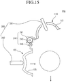
- Fig. 15 illustrates a state in which an ice piece is separated from a lower tray.
- an ice maker 200 including an ice separation mechanism includes an upper tray 110 and a lower tray 120 rotatably coupled to the upper tray 110 and formed of an elastically deformable material.
- the upper tray 110 may be formed of a metal material.
- Recessed parts 113 and 125 disposed on the upper and lower trays 110 and 120 define a shell 150 that provides a space for making a globular or spherical ice piece when the upper and lower trays 110 and 120 are closed. Thus, when water supplied into the shell 150 is frozen, globular or spherical ice may be made.
- An air hole 115 through which air within the shell 150 is exhausted may be defined in an upper portion of the upper tray 110. Also, the air hole 115 may have a size large enough to allow an upper ejecting pin 261 (that will be described in more detail below) to be accessible.
- a gasket may be further disposed between the upper tray 110 and the lower tray 120. When the upper tray 110 and the lower tray 120 are closed, the gasket may seal a space between the upper tray 110 and the lower tray 120 to reduce leakage of the water within the shell 150 to the outside.
- the ice maker 200 includes a driving unit 240 for operating the upper tray 110.
- the driving unit 240 includes a motor 241 for generating a rotation power, an upper plate gear 242 for rotating the upper tray 110, and a lower plate gear 243 for rotating the lower tray 120.
- the motor 241 may be directly or indirectly connected to the upper plate gear 242 or the lower plate gear 243 to rotate the upper plate gear 242 or the lower plate gear 243.
- the upper plate gear 242 is disposed on a rear end of the upper tray 110
- the lower plate gear 243 is disposed on a rear end of the lower tray 120.
- the upper plate gear 242 and the lower plate gear 243 are engaged with each other.
- the other gear may be rotated together with the one gear to closely attach or separate the upper tray 110 and the lower tray 120 to or from each other.
- the upper plate gear 242 has a diameter greater than or equal to that of the lower plate gear 243. As shown in Figs. 13 to 15 , if the lower plate gear 243 has a diameter less than that of the upper plate gear 243, the lower plate gear 243 may be rotated at a speed quicker than that of the upper plate gear 242. Thus, the lower tray 120 may have a rotation rate greater than that of the upper tray 110. With this design, the lower tray 120 has the rotation rate greater than that of the upper tray 110 and, therefore, an ice piece separated from the upper tray 110 drops directly into an ice storage part without dropping into or otherwise contacting the lower tray 120.
- the ice maker 200 includes an ejecting unit 260 for separating an ice made in the shell 150.
- the ejecting unit 260 includes an upper ejecting pin 261 disposed above the upper tray 110 and a lower ejecting pin 262 disposed under the lower tray 120.
- the upper ejecting pin 261 may pass through the air hole 115 to push the ice piece attached to the upper tray 110, thereby separating the ice piece from the upper tray 110.
- the lower ejecting pin 262 may push a central portion of the lower tray 120 to elastically deform the lower tray 120.
- an ice piece attached to the lower tray 120 is pushed by the deformation of the lower tray 120, and thus is separated from the lower tray 120.
- a globular or spherical ice piece made in a shell may be separated by an ejecting unit linked with a lower tray.
- other components except for the ejecting unit may be the same as those of the ice maker described above.
- the same components will be indicated by the same reference numerals, and their above detailed description will be referenced, rather than repeated.
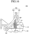
- Fig. 16 illustrates a side view of a state in which an example ice maker is closed.
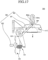
- Fig. 17 illustrates a side view of a state in which the example ice maker is opened.
- Figs. 18 to 21 show views successively illustrating an ice separation process of the example ice maker.
- an ice maker 300 includes an upper tray 110 formed of a metal material and a lower tray 120 of which at least a portion is formed of an elastic material. Also, the lower tray 120 is rotatably disposed on an upper tray 110. Further, the lower tray 120 is rotatably disposed by rotation of a driving unit (see reference numeral 140 of Fig. 3 ).
- a rotating arm 130 and an elastic member 131 are disposed on the lower tray 120.
- the lower tray 120 may be closely attached to the upper tray 110 by an elastic force of the elastic member 131.
- the ice maker 300 includes an ejecting unit 360 for separating an ice piece made in a shell 150 defined by coupling the upper tray 110 and the lower tray 120 to each other.
- the ejecting unit 360 includes a link 361, an upper ejecting pin 362, and a lower ejecting pin 363.
- the upper ejecting pin 362 is disposed above the upper tray 110.
- An upper ejecting pin 362 may be provided for each ice piece and the number of upper ejecting pins 362 may correspond to the number of shells 150.
- the plurality of upper ejecting pins 362 may extend from the bottom of a bar 362a that extends in a horizontal direction across a length of the upper tray 110.
- the link 361 has one end connected to the bar 362a and the other end connected to the rotating arm 130.
- An ejecting pin guide 364 for guiding a vertical movement of the bar 362a is disposed above the upper tray 110.
- a guide hole 364a vertically extends inside the ejecting pin guide 364.
- the lower ejecting pin 363 is disposed under the lower tray 120 and extends laterally. Thus, when the lower tray 120 is moved in a clockwise direction and thus completely opened, the lower ejecting pin 363 pushes a side of the lower tray 120 in which the made globular ice piece is received. Thus, the made ice piece within the lower tray 120 may be separated.
- water may be supplied in a state where the upper tray 110 and the lower tray 120 are closed.
- the ice making process may be performed.
- the lower tray 120 is rotated in a counterclockwise direction by an operation of the driving unit 140.
- the rotating arm 130 may be rotated together with the lower tray 120.
- the upper ejecting pin 362 is moved downward by the link 361. The downwardly moving upper ejecting pin 361 passes through an air hole 115 to push a globular or spherical ice piece made in the upper tray 110 downward.
- the driving unit 140 When the driving unit 140 is further rotated, as shown in Fig. 20 , the lower tray 120 is further rotated in a clockwise direction, and the upper ejecting pin 362 is further moved downward so that the ice disposed on the upper tray 110 drops toward the lower tray 120.
- the lower tray 120 is further rotated by the driving unit 140. That is, as shown in Fig. 21 , the lower tray 120 is rotated by about 90° in the clockwise direction. Here, a central portion of the lower tray 120 is pushed by the lower ejecting pin 363 and thus is deformed. Thus, the made globular ice piece may be separated from the lower tray 120 and then completely separated from the ice maker 300.
- a globular or spherical ice piece made in a shell may be separated by an ejecting unit linked with a lower tray. Also, when the ice is separated in this example, a heater heats an upper tray to assist the separation of the ice.
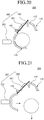
- Figs. 22 and 23 show views illustrating a separation process in an example ice maker.
- an ice maker 400 includes an upper tray 110 formed of a metal material and a lower tray 120 of which at least a portion is formed of an elastic material. Also, like the example ice maker 300, an upper ejecting pin 362 is connected to a link 361. Thus, when the lower tray 120 is rotated, the upper ejecting pin 362 is linked with the lower tray 120 and moved downward.
- an ice separation heater 465 is disposed on the upper tray 110.
- the ice separation heater 465 may be operated when or just before the lower tray 120 is rotated. That is, the ice separation heater 465 heats the upper tray 110 to melt a surface of the ice contacting the upper tray 110.
- the upper ejecting pin 362 may more easily push the ice to separate the ice from the upper tray 110.
- a lower ejecting pin 363 extends laterally under the lower tray 120. When the lower tray 120 is rotated, the lower ejecting pin 363 may push the lower tray 120 to separate an ice piece disposed on the lower tray 120.
- a driving unit 140 is operated for separating the made ice.
- the ice separation heater 465 may be operated. As the ice separation heater 465 is operated, the upper tray 110 is heated to melt a surface of the made ice contacting the upper tray 110. In a state where a portion of the surface of the made ice is melted, the driving unit 140 is operated, and thus, the lower tray 120 is rotated in a clockwise direction as shown in Fig. 22 .
- the ice moved downward is seated on the lower tray 120.
- the driving unit 140 is rotated to rotate the lower tray 120 by about 90° in a counterclockwise direction as shown in Fig. 23 .
- the lower ejecting pin 363 pushes a central portion of the lower tray 120 to deform the lower tray 120.
- the ice seated on the lower tray 120 is separated from the lower tray 120, and thus is completely separated from the ice maker 400.
- an ice made in a shell is separated by an ejecting unit linked with a lower tray.
- a heater heats an upper tray and the lower tray to assist the separation of the ice.
- Figs. 24 and 25 show views illustrating an example ice separation process in an example ice maker.
- an ice maker 500 includes an upper tray 510 and a lower tray 520.
- Each of the upper tray 510 and the lower tray 520 is formed of a metal material to provide superior thermal conductivity. Thus, the ice making process and the ice separation process may be easily performed.
- recessed parts 513 and 525 are respectively disposed on positions corresponding to the upper tray 510 and the lower tray 520. When the upper tray 510 and the lower tray 520 are closed, the recessed parts 513 and 525 contact each other to form a shell in which a globular or spherical ice piece is made.
- an ejecting unit 560 includes upper ejecting pins 562 respectively passing through air holes 515 of the upper tray 510 to push ice pieces, a bar (not shown) to which the plurality of upper ejecting pins 562 are connected, a link 561 having an end connected to the bar, and upper and lower ice separation heaters 564 and 565 respectively disposed on outer surfaces of the upper and lower trays 510 and 520.
- the upper and lower ice separation heaters 564 and 565 may respectively heat the upper and lower trays 510 and 520 to melt a surface of each of the ice pieces contacting the upper tray 510.
- each of the upper ejecting pins 562 may push the ice to more easily separate the ice from the upper tray 510.
- the lower ice separation heater 565 is operated first to heat the lower tray 520, thereby separating the made ice from the lower tray 520.
- the lower tray 520 is heated, a surface of a lower portion of an ice piece contacting the lower tray 520 is melted.
- the lower tray 520 is rotated in a clockwise direction.
- the made ice has a melted lower surface, the ice is separated from the lower tray 520 to become in a state of Fig. 24 .
- the upper ice separation heater 564 is operated.
- the upper tray 510 is heated to melt a surface of an upper portion of an ice contacting the upper tray 510.
- an upper ejecting pin 562 is moved downward to move the ice disposed on the upper tray 510 downward as shown in Fig. 25 .
- the upper ejecting pin 562 may pass through the air hole 515 to push the ice, thereby separating the ice from the ice maker 500.
- an ejecting unit which does not include the ejecting pin 562 and the link 561 may be applied to the ice maker 500. That is, in the structure of the ice maker 500, an ejecting unit in which the upper ice separation heater 564 and the lower ice separation heater 565 are respectively mounted on a top surface of the upper tray 510 and a bottom surface of the lower tray 520 without including a separate ejecting pin may be applicable. According to the ice separation process in this structure, the lower ice separation heater 565 is operated first to separate a lower portion of the ice from the lower tray 520, and then, the lower tray 520 is rotated downward (in the clockwise direction in Fig. 25 ).
- the globular or spherical ice pieces may be maintained in a state where the ice is attached to the upper tray 510.
- the upper ice separation heater 564 may be operated to separate the ice from the upper tray 510. Then, the separated ice may drop directly into an ice storage container.
- upper and lower trays may be rotated by rotation of a driving unit and then moved in left and right directions to separate ice pieces disposed on both sides thereof by ejecting pins.
- Fig. 26 illustrates a side view of an example ice maker.
- Figs. 27 to 29 show views successively illustrating an operation of the example ice maker.
- an ice maker 600 includes a case 610 defining an outer appearance thereof, upper and lower trays 620 and 640 disposed within the case 610, a driving unit 670 for operating the upper and lower trays 620 and 640, upper and lower racks 630 and 650 respectively connected to both sides of the upper and lower trays 620 and 640 to transmit a power of the driving unit 670, and ejecting pins 611 for separating made ice pieces.
- the case 610 may receive the upper tray 620 and the lower tray 640. Also, the case 610 is mounted inside the freezing compartment (see reference numeral 4 of Fig. 1 ).
- the ejecting pin 611 horizontally extends from both side surfaces of the case 610 corresponding to front and rear surfaces of the trays 620 and 640.
- the ejecting pins 611 are respectively disposed at positions corresponding to a recessed part 621 of the upper tray 620 and a recessed part 641 of the lower tray 640, which will be described in more detail below.
- the ejecting pins 611 may have the same height and be disposed facing each other.
- upper and lower guide protrusions 612 and 613 are disposed on both side surfaces of the case 610 corresponding to both sides of the trays 620 and 640, respectively.
- the upper guide protrusions 612 are disposed on an upper portion of the case 610, and the lower guide protrusions 613 are disposed on a lower portion of the case 610.
- upper and lower guide grooves 631 and 651 are defined in upper and lower racks 630 and 650, respectively.
- a plurality of recessed parts 621 are successively arranged in a line in the upper tray 620. At least the recessed part 621 of the upper tray 620 may be formed of an elastically deformable material.
- the upper rack 630 extends downward from both side surfaces of the upper tray 620. Also, the upper rack 630 is engaged with a pinion 660 that will be described in more detail below.
- the pinion 660 is connected to a rotation shaft of the driving unit 670. Also, when the upper tray 620 is rotated by about 90° in a counterclockwise direction, the upper rack 630 is restricted by the upper guide protrusion 612 and thus is not rotated.
- the lower tray 640 is disposed under the upper tray 620.
- a plurality of recessed parts 641 are successively arranged in a line in the lower tray 640.
- the lower tray 640 may be coupled to the upper tray 620 and closed. In a state where the upper tray 620 and the lower tray 640 are closed, each of the recessed parts 641 defines a shell that provides a space for making a globular or spherical ice piece.
- At least the recessed part 641 of the lower tray 640 is formed of an elastically deformable material.
- the lower rack 650 is disposed on each of both side surfaces of the lower tray 640.
- the lower rack 650 extends downward from each of both side surfaces of the lower tray 640.
- the lower rack 650 is engaged with the pinion 660.
- a water supply part, an air hole, and a water path may be provided in each of the upper and lower trays 620 and 640, as described in the examples explained above.
- the driving unit 670 may be provided to a side of the upper and lower trays 620 and 640.
- the pinion 660 is mounted on a rotation center of the driving unit 670.
- the pinion 660 may have the same rotation center as those of the upper and lower trays 620 and 640.
- the upper rack 630 and the lower rack 650 are gear-coupled to each other. Thus, when the pinion 660 is rotated, the upper rack 630 and the lower rack 650 may be moved with respect to each other.
- the upper and lower trays 620 and 640 are coupled to each other so that water is supplied into a shell for making an ice piece.
- water for making an ice piece is supplied through a water supply part 622.
- a cooling process is performed for a preset time to form an ice piece.
- the driving unit 670 When the globular or spherical ice piece is completely made in the shell (e.g., frozen), the driving unit 670 is operated.
- the driving unit 670 when the driving unit 670 is rotated, the pinion 660 is rotated together with the driving unit 670.
- the upper and lower racks 630 and 650 which are engaged with the pinion 660 are rotated also.
- the lower guide protrusion 613 is moved along the upper guide groove 631 defined in the upper rack 630, and substantially, the upper rack 630 is rotated.
- the upper guide protrusion 612 is moved along the lower guide groove 651, the lower rack 650 is rotated also.
- Each of the guide grooves 631 and 651 may have a length enough to separate the guide protrusions 612 and 613 from the guide grooves 631 and 651 when the upper and lower racks 630 and 650 are rotated by about 90°.
- the upper and lower racks 630 and 650 are stopped at positions, at which each of the upper and lower racks 630 and 650 is rotated by about 90°, by the guide protrusions 613 and 612 disposed on sides opposite to those of the guide protrusions 612 and 613 moving along the guide grooves 631 and 651 respectively defined in the racks 630 and 650.
- the pinion 660 is further rotated also. Since the upper and lower rocks 630 and 650 are stopped by the guide protrusions 613 and 612 disposed on the sides opposite to those of the guide protrusions 612 and 613 moving along the guide grooves 631 and 651 respectively defined in the racks 630 and 650, the upper and lower racks 630 and 650 are linearly moved. That is, in the drawings, the upper rack 630 is moved in a left direction, and the lower rack 650 is moved in a right direction. As a result, the upper tray 620 integrally coupled to the upper rack 630 also may be moved in the left direction. The lower tray 620 integrally coupled to the lower rack 650 also may be moved in the right direction.
- the pinion 660 When the pinion 660 is further rotated, the upper and lower trays 620 and 640 are separated from each other, and then are moved in the left and right directions, respectively.
- the recessed parts 621 and 641 of the upper and lower trays 620 and 640 are pushed by the ejecting pins 611 disposed on both sides of the case 610. Accordingly, the recessed parts 621 and 641 are pushed and deformed, and thus the ice pieces disposed in the recessed parts 621 and 641 are pushed to drop down.
- the driving unit 670 is reversely rotated. Also, the upper and lower trays 620 and 640 are moved in a reverse order of the above-described order, and then return to a standby state for receiving water.
- ice pieces are made in the plurality of shells which provide globular or spherical spaces, respectively.
- globular or spherical ice pieces may be made to minimize a contact area between the ice pieces when the ice pieces are stored, thereby reducing the ice pieces from being matted or stuck with respect to each other.
- the water supply part for supplying water may be disposed on the upper tray, and the air hole for exhausting air may be defined in the upper tray corresponding to each of shells.
- the shells may communicate with each other by the water path.
- water may be smoothly supplied into the shells by the water path.
- the ejecting units for separating ice pieces made in the shells may be disposed outside the upper tray and the lower tray.
- the made ice pieces may be easily separated, thereby enabling a continuous ice making process.
Landscapes
- Engineering & Computer Science (AREA)
- Physics & Mathematics (AREA)
- Mechanical Engineering (AREA)
- Thermal Sciences (AREA)
- General Engineering & Computer Science (AREA)
- Production, Working, Storing, Or Distribution Of Ice (AREA)
Claims (5)
- Appareil de production de glace comprenant :un plateau supérieur (620) comprenant une pluralité de premières parties évidées (621), chacune des premières parties évidées (621) ayant une forme hémisphérique ;un plateau inférieur (640) comprenant une pluralité de secondes parties évidées (641), chacune des secondes parties évidées (641) ayant une forme hémisphérique ;une unité d'entraînement (670) qui est connectée à l'un au moins du plateau supérieur (620) et du plateau inférieur (640) et qui est configurée pour déplacer l'un au moins du plateau supérieur (620) et du plateau inférieur (640) pour changer entre une position attachée dans laquelle les premières parties évidées (621) du plateau supérieur (620) sont attachées aux secondes parties évidées (641) du plateau inférieur (640) pour définir une pluralité de coques sphériques et dans une position séparée dans laquelle les premières parties évidées (621) du plateau supérieur (620) sont séparées des secondes parties évidées (641) du plateau inférieur (640) ;une partie d'alimentation d'eau (622) configurée pour alimenter de l'eau dans les coques définies dans la position attachée ;une unité d'éjection qui est disposée à l'extérieur des coques et qui est configurée pour faciliter la séparation des morceaux de glace produits dans les coques, depuis l'un au moins du plateau supérieur et du plateau inférieur,une unité de transmission de puissance qui connecte l'unité d'entraînement (670) au plateau supérieur (620) et au plateau inférieur (640), l'unité de transmission de puissance étant configurée pour séparer le plateau supérieur (620) et le plateau inférieur (640) l'un par rapport à l'autre,dans lequel l'unité d'entraînement (670) comprend un moteur,dans lequel l'unité de transmission de puissance comprend :un pignon (660) connecté à un arbre rotatif du moteur,caractérisépar une crémaillère supérieure (630) attachée au plateau supérieur (620),par une crémaillère inférieure (650) attachée au plateau inférieur (640),les éléments de crémaillère supérieure (630) et de crémaillère inférieure (650) étant engagés avec le pignon (660),dans lequel, depuis une position dans laquelle la crémaillère supérieure est face à la crémaillère inférieure par rapport au pignon, la crémaillère supérieure s'étend dans une direction opposée à la crémaillère inférieure,dans lequel l'appareil de production de glace comprend en outre :un boîtier (610) recevant le plateau supérieur (620) et le plateau inférieur (640),une première gorge de guidage (631) ayant une courbure prédéterminée et s'étendant sous une forme en arc dans la crémaillère supérieure (630),une seconde gorge de guidage (651) ayant une courbure prédéterminée et s'étendant sous une forme en arc dans la crémaillère inférieure (650),au moins une projection de guidage supérieure (612) qui se projette depuis une surface latérale du boîtier (610),au moins une projection de guidage inférieure (613) qui se projette depuis la surface latérale du boîtier (610),dans lequel ladite au moins une projection supérieure et ladite au moins une projection inférieure (612, 613) sont respectivement logées dans la première et la seconde gorge de guidage (631, 651) pour guider une rotation de la crémaillère supérieure (620) et de la crémaillère inférieure (640).
- Appareil de production de glace selon la revendication 1, dans lequel l'unité d'éjection inclut des broches d'éjection (611) disposées sur les deux côtés du boîtier (610) et configurées pour pousser et pour déformer les premières et les secondes parties évidées (621, 641).
- Appareil de production de glace selon la revendication 1, dans lequel les projections de guidage (612, 613) sont espacées les unes des autres par rapport à un centre de rotation du moteur et agencées en parallèle à des positions face-à-face.
- Appareil de production de glace selon la revendication 3, dans lequel les projections de guidage (612, 613) sont configurées pour être respectivement séparées de la première gorge de guidage (631) et de la seconde gorge de guidage (651) à une rotation d'environ 90° de chacune de la crémaillère supérieure et de la crémaillère inférieure, ladite au moins une projection de guidage supérieure (612) est configurée pour arrêter la rotation de la crémaillère supérieure, et ladite au moins une projection de guidage inférieure (613) est configurée pour arrêter la rotation de la crémaillère inférieure (650).
- Appareil de production de glace selon la revendication 4, dans lequel, après que la rotation de la crémaillère supérieure (630) a été arrêtée et que la rotation de la crémaillère inférieure (650) a été arrêtée, une rotation du pignon (660) provoque un mouvement linéaire de la crémaillère supérieure (630) et de la crémaillère inférieure (650) dans des directions opposées pour séparer le plateau supérieur et le plateau inférieur (620, 640) l'un par rapport à l'autre.
Applications Claiming Priority (1)
| Application Number | Priority Date | Filing Date | Title |
|---|---|---|---|
| KR1020110070358A KR101890939B1 (ko) | 2011-07-15 | 2011-07-15 | 아이스 메이커 |
Publications (3)
| Publication Number | Publication Date |
|---|---|
| EP2549207A2 EP2549207A2 (fr) | 2013-01-23 |
| EP2549207A3 EP2549207A3 (fr) | 2015-08-19 |
| EP2549207B1 true EP2549207B1 (fr) | 2017-04-12 |
Family
ID=46650306
Family Applications (1)
| Application Number | Title | Priority Date | Filing Date |
|---|---|---|---|
| EP12005167.7A Active EP2549207B1 (fr) | 2011-07-15 | 2012-07-13 | Dispositif de fabrication de glace |
Country Status (4)
| Country | Link |
|---|---|
| US (1) | US9234688B2 (fr) |
| EP (1) | EP2549207B1 (fr) |
| KR (1) | KR101890939B1 (fr) |
| CN (1) | CN102878743B (fr) |
Cited By (6)
| Publication number | Priority date | Publication date | Assignee | Title |
|---|---|---|---|---|
| EP4235063A3 (fr) * | 2018-11-16 | 2023-10-18 | LG Electronics Inc. | Machine à glaçons et réfrigérateur |
| EP4300013A3 (fr) * | 2018-11-16 | 2024-03-13 | LG Electronics Inc. | Appareil à glaçons et réfrigérateur |
| EP4306879A3 (fr) * | 2018-11-16 | 2024-04-03 | LG Electronics Inc. | Machine à glaçons et réfrigérateur |
| US12410959B2 (en) | 2020-10-29 | 2025-09-09 | Samsung Electronics Co., Ltd. | Refrigerator |
| EP4603767A3 (fr) * | 2018-11-16 | 2025-10-22 | LG Electronics Inc. | Machine à glaçons et réfrigérateur |
| EP4679013A3 (fr) * | 2018-11-16 | 2026-03-18 | LG Electronics Inc. | Appareil de fabrication de glaçons et réfrigérateur |
Families Citing this family (180)
| Publication number | Priority date | Publication date | Assignee | Title |
|---|---|---|---|---|
| KR102731115B1 (ko) * | 2018-10-02 | 2024-11-18 | 엘지전자 주식회사 | 제빙기 및 이를 포함하는 냉장고 |
| KR102657068B1 (ko) * | 2018-11-16 | 2024-04-15 | 엘지전자 주식회사 | 아이스 메이커의 제어방법 |
| KR102709377B1 (ko) * | 2018-10-02 | 2024-09-25 | 엘지전자 주식회사 | 제빙기 및 이를 포함하는 냉장고 |
| KR102669631B1 (ko) * | 2018-10-02 | 2024-05-28 | 엘지전자 주식회사 | 제빙기 및 이를 포함하는 냉장고 |
| KR102636442B1 (ko) * | 2018-10-02 | 2024-02-15 | 엘지전자 주식회사 | 제빙기 및 이를 포함하는 냉장고 |
| KR102009350B1 (ko) * | 2012-06-12 | 2019-08-09 | 엘지전자 주식회사 | 냉장고의 제어 방법 |
| KR102130632B1 (ko) * | 2013-01-02 | 2020-07-06 | 엘지전자 주식회사 | 아이스 메이커 |
| US9272444B2 (en) | 2013-07-18 | 2016-03-01 | Propeller, Inc. | Ice mold |
| KR102186818B1 (ko) * | 2013-08-30 | 2020-12-04 | 코웨이 주식회사 | 제빙기 |
| US9528737B2 (en) * | 2013-10-31 | 2016-12-27 | Pepsico, Inc. | Ice making and harvesting |
| KR101660962B1 (ko) * | 2014-08-29 | 2016-09-29 | 김대영 | 구형 얼음을 제빙할 수 있는 제빙장치 및 방법 |
| WO2016032251A1 (fr) * | 2014-08-29 | 2016-03-03 | 김대영 | Appareil de fabrication de glace et procédé permettant de fabriquer de la glace sphérique |
| AU2015330055A1 (en) * | 2014-10-06 | 2017-05-11 | Icebreaker Nordic Aps | Ice cube producing unit |
| CN105546898B (zh) * | 2016-01-13 | 2018-05-08 | 中国航空动力机械研究所 | 航空发动机吞冰试验用冰雹的制冰模具及制作方法 |
| KR200487660Y1 (ko) * | 2017-11-29 | 2018-10-17 | 박상준 | 잉곳 성형금형 |
| US10697684B2 (en) * | 2018-03-20 | 2020-06-30 | Bsh Home Appliances Corporation | Automatic ice-sphere-making system for refrigerator appliance |
| CN108759215A (zh) * | 2018-07-06 | 2018-11-06 | 无锡风电设计研究院有限公司 | 一种用于在基体上制备成型冰块的制冰装置 |
| BR102019015737A2 (pt) * | 2018-08-01 | 2020-02-18 | Lg Electronics Inc. | Refrigerador |
| US11112159B2 (en) | 2018-08-01 | 2021-09-07 | Lg Electronics Inc. | Refrigerator |
| KR102636440B1 (ko) * | 2018-10-02 | 2024-02-15 | 엘지전자 주식회사 | 제빙기 및 이를 포함하는 냉장고 |
| KR102630212B1 (ko) * | 2018-10-02 | 2024-01-29 | 엘지전자 주식회사 | 제빙기 및 이를 포함하는 냉장고 |
| CN112789470B (zh) * | 2018-10-02 | 2023-09-22 | Lg电子株式会社 | 冰箱及其控制方法 |
| US12013167B2 (en) | 2018-10-02 | 2024-06-18 | Lg Electronics Inc. | Refrigerator |
| KR102897475B1 (ko) * | 2019-07-06 | 2025-12-10 | 엘지전자 주식회사 | 제빙기 및 냉장고 |
| KR102912690B1 (ko) * | 2019-07-06 | 2026-01-15 | 엘지전자 주식회사 | 제빙기 및 냉장고 |
| KR102637434B1 (ko) * | 2018-10-02 | 2024-02-19 | 엘지전자 주식회사 | 제빙기 및 이를 포함하는 냉장고 |
| KR102892556B1 (ko) * | 2019-07-06 | 2025-12-01 | 엘지전자 주식회사 | 냉장고 및 그의 제어방법 |
| CN116164465A (zh) * | 2018-10-02 | 2023-05-26 | Lg电子株式会社 | 冰箱 |
| KR102665703B1 (ko) * | 2018-10-02 | 2024-05-14 | 엘지전자 주식회사 | 제빙기 및 이를 포함하는 냉장고 |
| AU2019353487B2 (en) | 2018-10-02 | 2023-03-23 | Lg Electronics Inc. | Refrigerator and method for controlling same |
| US11892220B2 (en) | 2018-10-02 | 2024-02-06 | Lg Electronics Inc. | Refrigerator and method for controlling same |
| CN112771337B (zh) * | 2018-10-02 | 2023-07-04 | Lg电子株式会社 | 冰箱 |
| US11874043B2 (en) | 2018-10-02 | 2024-01-16 | Lg Electronics Inc. | Refrigerator |
| US12135157B2 (en) | 2018-10-02 | 2024-11-05 | Lg Electronics Inc. | Refrigerator |
| KR102729731B1 (ko) * | 2018-10-02 | 2024-11-14 | 엘지전자 주식회사 | 제빙기 및 이를 포함하는 냉장고 |
| KR102850804B1 (ko) * | 2019-09-11 | 2025-08-26 | 엘지전자 주식회사 | 냉장고 |
| WO2020071790A1 (fr) * | 2018-10-02 | 2020-04-09 | 엘지전자 주식회사 | Réfrigérateur et son procédé de commande |
| EP3862687B1 (fr) * | 2018-10-02 | 2025-01-08 | LG Electronics Inc. | Réfrigérateur |
| WO2020071791A1 (fr) * | 2018-10-02 | 2020-04-09 | 엘지전자 주식회사 | Réfrigérateur et procédé de commande associé |
| WO2020071741A1 (fr) | 2018-10-02 | 2020-04-09 | 엘지전자 주식회사 | Réfrigérateur et son procédé de commande |
| AU2019354482B2 (en) | 2018-10-02 | 2023-04-06 | Lg Electronics Inc. | Refrigerator and control method therefor |
| WO2020071766A1 (fr) | 2018-10-02 | 2020-04-09 | 엘지전자 주식회사 | Réfrigérateur et son procédé de commande |
| KR102864260B1 (ko) * | 2019-09-11 | 2025-09-26 | 엘지전자 주식회사 | 냉장고 |
| KR102824128B1 (ko) * | 2019-07-06 | 2025-06-24 | 엘지전자 주식회사 | 냉장고 |
| WO2020071772A1 (fr) * | 2018-10-02 | 2020-04-09 | 엘지전자 주식회사 | Réfrigérateur |
| EP4647686A1 (fr) * | 2018-10-02 | 2025-11-12 | LG Electronics Inc. | Réfrigérateur et son procédé de commande |
| EP3862679B1 (fr) * | 2018-10-02 | 2025-04-09 | LG Electronics Inc. | Réfrigérateur |
| US11674730B2 (en) | 2018-10-02 | 2023-06-13 | Lg Electronics Inc. | Ice maker and refrigerator including same |
| KR102869804B1 (ko) * | 2019-09-17 | 2025-10-14 | 엘지전자 주식회사 | 냉장고 |
| EP4575358A3 (fr) * | 2018-10-02 | 2025-08-27 | LG Electronics Inc. | Refrigerator |
| EP3862696A4 (fr) | 2018-10-02 | 2022-07-20 | LG Electronics Inc. | Réfrigérateur et son procédé de commande |
| EP3862668B1 (fr) * | 2018-10-02 | 2026-04-08 | LG Electronics Inc. | Machine à glaçons et réfrigérateur équipé de celle-ci |
| KR102778429B1 (ko) * | 2019-07-06 | 2025-03-12 | 엘지전자 주식회사 | 제빙기 및 냉장고 |
| CN112771331B (zh) * | 2018-10-02 | 2023-01-17 | Lg电子株式会社 | 冰箱 |
| US12111089B2 (en) | 2018-10-02 | 2024-10-08 | Lg Electronics Inc. | Refrigerator |
| AU2019355698B2 (en) | 2018-10-02 | 2023-04-20 | Lg Electronics Inc. | Refrigerator |
| EP4729862A2 (fr) * | 2018-10-02 | 2026-04-22 | LG Electronics Inc. | Machine à glaçons et réfrigérateur équipé de celle-ci |
| EP3862707B1 (fr) | 2018-10-02 | 2025-07-23 | LG Electronics Inc. | Réfrigérateur et son procédé de commande |
| US11971204B2 (en) | 2018-10-02 | 2024-04-30 | Lg Electronics Inc. | Refrigerator |
| CN112771333A (zh) | 2018-10-02 | 2021-05-07 | Lg电子株式会社 | 冰箱及其控制方法 |
| CN116086086A (zh) | 2018-10-02 | 2023-05-09 | Lg电子株式会社 | 冰箱 |
| KR102662710B1 (ko) * | 2018-10-02 | 2024-05-03 | 엘지전자 주식회사 | 제빙기 및 이를 포함하는 냉장고 |
| KR102847118B1 (ko) * | 2019-09-02 | 2025-08-19 | 엘지전자 주식회사 | 냉장고 |
| WO2020071786A1 (fr) | 2018-10-02 | 2020-04-09 | 엘지전자 주식회사 | Machine à glaçons et réfrigérateur équipé de celle-ci |
| EP3862691B1 (fr) * | 2018-10-02 | 2026-03-04 | LG Electronics Inc. | Réfrigérateur |
| EP4696959A3 (fr) | 2018-10-02 | 2026-04-15 | LG Electronics Inc. | Réfrigérateur |
| EP4679014A3 (fr) | 2018-10-02 | 2026-03-18 | LG Electronics Inc. | Réfrigérateur et son procédé de commande |
| WO2020071751A1 (fr) | 2018-10-02 | 2020-04-09 | 엘지전자 주식회사 | Réfrigérateur |
| US11898785B2 (en) | 2018-10-02 | 2024-02-13 | Lg Electronics Inc. | Refrigerator |
| CN116892810A (zh) | 2018-10-02 | 2023-10-17 | Lg电子株式会社 | 制冰器 |
| CN112789459A (zh) * | 2018-10-02 | 2021-05-11 | Lg电子株式会社 | 制冰器及包括其的冰箱 |
| US12117225B2 (en) | 2018-10-02 | 2024-10-15 | Lg Electronics Inc. | Refrigerator |
| KR102664673B1 (ko) * | 2018-10-02 | 2024-05-10 | 엘지전자 주식회사 | 제빙기 및 이를 포함하는 냉장고 |
| KR102671449B1 (ko) * | 2018-10-02 | 2024-05-31 | 엘지전자 주식회사 | 제빙기 및 이를 포함하는 냉장고 |
| US11988431B2 (en) | 2018-10-02 | 2024-05-21 | Lg Electronics Inc. | Icemaker and refrigerator |
| KR102847803B1 (ko) * | 2019-09-03 | 2025-08-19 | 엘지전자 주식회사 | 냉장고 |
| CN115289763B (zh) | 2018-10-02 | 2023-07-04 | Lg电子株式会社 | 冰箱 |
| CN112771335B (zh) * | 2018-10-02 | 2023-08-29 | Lg电子株式会社 | 冰箱及其控制方法 |
| US11906230B2 (en) | 2018-10-02 | 2024-02-20 | Lg Electronics Inc. | Refrigerator |
| WO2020071760A1 (fr) * | 2018-10-02 | 2020-04-09 | 엘지전자 주식회사 | Réfrigérateur |
| CN117168039A (zh) | 2018-10-02 | 2023-12-05 | Lg电子株式会社 | 制冰器 |
| US12209787B2 (en) | 2018-10-02 | 2025-01-28 | Lg Electronics Inc. | Refrigerator |
| EP4530559A3 (fr) * | 2018-10-02 | 2025-05-21 | LG Electronics Inc. | Réfrigérateur |
| KR102869782B1 (ko) * | 2019-07-06 | 2025-10-15 | 엘지전자 주식회사 | 냉장고 및 그의 제어방법 |
| US12104839B2 (en) | 2018-10-02 | 2024-10-01 | Lg Electronics Inc. | Ice maker and refrigerator comprising same |
| WO2020071792A1 (fr) * | 2018-10-02 | 2020-04-09 | 엘지전자 주식회사 | Réfrigérateur |
| CN116972591A (zh) | 2018-10-02 | 2023-10-31 | Lg电子株式会社 | 制冰器 |
| WO2020101384A1 (fr) * | 2018-11-16 | 2020-05-22 | Lg Electronics Inc. | Machine à glaçons et réfrigérateur |
| KR102822926B1 (ko) * | 2018-11-16 | 2025-06-20 | 엘지전자 주식회사 | 아이스 메이커 |
| EP4123245A1 (fr) * | 2018-11-16 | 2023-01-25 | LG Electronics Inc. | Appareil de fabrication de glaçons et réfrigérateur |
| EP4336130A1 (fr) | 2018-11-16 | 2024-03-13 | LG Electronics Inc. | Appareil domestique avec un dispositif pour faire de la glace |
| KR102833937B1 (ko) * | 2019-08-30 | 2025-07-11 | 엘지전자 주식회사 | 아이스 메이커 및 냉장고 |
| AU2019378528B2 (en) | 2018-11-16 | 2023-05-25 | Lg Electronics Inc. | Ice maker and refrigerator |
| EP4001800A1 (fr) | 2018-11-16 | 2022-05-25 | LG Electronics Inc. | Dispositif de fabrication de glace |
| EP3653968B1 (fr) * | 2018-11-16 | 2024-01-03 | LG Electronics Inc. | Appareil domestique avec une machine à faire de la glace |
| KR102823935B1 (ko) * | 2018-11-16 | 2025-06-23 | 엘지전자 주식회사 | 아이스 메이커 및 이를 구비하는 냉장고 |
| KR102692985B1 (ko) * | 2018-11-16 | 2024-08-06 | 엘지전자 주식회사 | 아이스 메이커 및 냉장고 |
| KR102837651B1 (ko) * | 2019-09-06 | 2025-07-22 | 엘지전자 주식회사 | 아이스 메이커 |
| KR102818065B1 (ko) * | 2019-07-06 | 2025-06-10 | 엘지전자 주식회사 | 아이스 메이커 및 냉장고 |
| KR102832260B1 (ko) * | 2018-11-16 | 2025-07-09 | 엘지전자 주식회사 | 아이스 메이커 및 냉장고 |
| KR102737086B1 (ko) * | 2019-03-22 | 2024-11-29 | 엘지전자 주식회사 | 아이스 메이커 및 냉장고 |
| ES3008514T3 (en) * | 2018-11-16 | 2025-03-24 | Lg Electronics Inc | Ice maker and refrigerator |
| AU2019378525A1 (en) * | 2018-11-16 | 2021-06-24 | Lg Electronics Inc. | Ice maker and refrigerator |
| KR102660521B1 (ko) * | 2018-11-16 | 2024-04-24 | 엘지전자 주식회사 | 아이스 메이커 및 냉장고 |
| KR102820435B1 (ko) * | 2019-07-06 | 2025-06-12 | 엘지전자 주식회사 | 아이스 메이커 및 냉장고 |
| CN113167522B (zh) * | 2018-11-16 | 2023-05-23 | Lg电子株式会社 | 冰箱 |
| EP4656976A1 (fr) * | 2018-11-16 | 2025-12-03 | LG Electronics Inc. | Appareil de fabrication de glaçons et réfrigérateur |
| KR102795654B1 (ko) * | 2019-07-06 | 2025-04-15 | 엘지전자 주식회사 | 아이스 메이커 |
| US12072132B2 (en) * | 2018-11-16 | 2024-08-27 | Lg Electronics Inc. | Ice maker and refrigerator |
| CN114838546B (zh) * | 2018-11-16 | 2023-12-29 | Lg电子株式会社 | 制冰器及冰箱 |
| KR102841362B1 (ko) * | 2019-09-06 | 2025-07-31 | 엘지전자 주식회사 | 아이스 메이커 |
| US11959685B2 (en) * | 2018-11-16 | 2024-04-16 | Lg Electronics Inc. | Ice maker and refrigerator |
| US11313603B2 (en) | 2018-11-16 | 2022-04-26 | Lg Electronics Inc. | Ice maker and refrigerator |
| CN113056645A (zh) * | 2018-11-16 | 2021-06-29 | Lg电子株式会社 | 冰箱 |
| KR102847874B1 (ko) * | 2019-09-02 | 2025-08-19 | 엘지전자 주식회사 | 냉장고 |
| US11578904B2 (en) | 2018-11-16 | 2023-02-14 | Lg Electronics Inc. | Ice maker and refrigerator |
| WO2020101368A1 (fr) * | 2018-11-16 | 2020-05-22 | Lg Electronics Inc. | Machine à glaçons et réfrigérateur |
| KR102736443B1 (ko) * | 2019-03-22 | 2024-11-28 | 엘지전자 주식회사 | 아이스 메이커 및 냉장고 |
| KR102838723B1 (ko) * | 2019-09-06 | 2025-07-24 | 엘지전자 주식회사 | 아이스 메이커 |
| US11874045B2 (en) | 2018-11-16 | 2024-01-16 | Lg Electronics Inc. | Ice maker and refrigerator |
| KR102927210B1 (ko) * | 2019-07-06 | 2026-02-12 | 엘지전자 주식회사 | 아이스 메이커 및 냉장고 |
| KR102811758B1 (ko) * | 2019-07-06 | 2025-05-22 | 엘지전자 주식회사 | 아이스 메이커 및 냉장고 |
| KR102796207B1 (ko) * | 2019-07-06 | 2025-04-16 | 엘지전자 주식회사 | 아이스 메이커 |
| KR102925532B1 (ko) * | 2019-07-06 | 2026-02-09 | 엘지전자 주식회사 | 아이스 메이커 및 냉장고 |
| KR102753565B1 (ko) * | 2019-03-22 | 2025-01-14 | 엘지전자 주식회사 | 아이스 메이커 및 냉장고 |
| KR102753564B1 (ko) * | 2019-03-22 | 2025-01-14 | 엘지전자 주식회사 | 아이스 메이커 및 냉장고 |
| KR102812728B1 (ko) * | 2019-07-06 | 2025-05-23 | 엘지전자 주식회사 | 냉장고 |
| KR102928398B1 (ko) * | 2019-07-06 | 2026-02-13 | 엘지전자 주식회사 | 아이스 메이커 및 냉장고 |
| KR102676672B1 (ko) | 2018-11-19 | 2024-06-20 | 엘지전자 주식회사 | 아이스 메이커 및 냉장고 |
| US11946681B2 (en) | 2018-11-22 | 2024-04-02 | Icebreaker International Aps | Ice cube producing unit |
| CN111288700B (zh) * | 2018-12-06 | 2022-06-24 | 海尔智家股份有限公司 | 制冰组件及具有其的冰箱 |
| KR102782080B1 (ko) * | 2019-03-22 | 2025-03-13 | 엘지전자 주식회사 | 아이스 메이커 및 냉장고 |
| KR102793014B1 (ko) * | 2019-06-14 | 2025-04-07 | 엘지전자 주식회사 | 냉장고 및 아이스 메이커의 제어방법 |
| KR102779593B1 (ko) * | 2019-06-19 | 2025-03-12 | 엘지전자 주식회사 | 냉장고 및 그의 제어방법 |
| US11408661B2 (en) * | 2019-06-19 | 2022-08-09 | Haier Us Appliance Solutions, Inc. | Single cord ice press assembly |
| KR102782085B1 (ko) * | 2019-06-26 | 2025-03-13 | 엘지전자 주식회사 | 냉장고 및 그의 제어방법 |
| US20220357088A1 (en) * | 2019-06-26 | 2022-11-10 | Lg Electronics Inc. | Refrigerator and method for controlling the same |
| KR102787640B1 (ko) * | 2019-06-28 | 2025-03-27 | 엘지전자 주식회사 | 아이스 메이커의 제어방법 |
| KR102801514B1 (ko) * | 2019-07-06 | 2025-04-29 | 엘지전자 주식회사 | 아이스 메이커의 제어방법 |
| AU2020309996B2 (en) * | 2019-07-06 | 2023-09-28 | Lg Electronics Inc. | Refrigerator |
| WO2021006587A1 (fr) * | 2019-07-06 | 2021-01-14 | 엘지전자 주식회사 | Procédé de commande de machine à glaçons |
| KR102809604B1 (ko) * | 2019-07-06 | 2025-05-16 | 엘지전자 주식회사 | 아이스 메이커 |
| KR102797355B1 (ko) * | 2019-07-06 | 2025-04-21 | 엘지전자 주식회사 | 아이스 메이커의 제어방법 |
| KR102925533B1 (ko) * | 2019-07-06 | 2026-02-09 | 엘지전자 주식회사 | 냉장고 |
| KR102871857B1 (ko) * | 2019-11-12 | 2025-10-15 | 엘지전자 주식회사 | 아이스 메이커의 제어방법 |
| CN113237260A (zh) * | 2020-01-22 | 2021-08-10 | 青岛海尔电冰箱有限公司 | 制冰模组及制冰方法 |
| IT202000001342A1 (it) * | 2020-01-23 | 2021-07-23 | Dino Nasci | Macchina per produrre ghiaccio |
| KR200494411Y1 (ko) * | 2020-06-15 | 2021-10-07 | 최용재 | 얼음용 트레이 구조체 |
| KR102392198B1 (ko) | 2020-09-18 | 2022-04-28 | 청호나이스 주식회사 | 구형 또는 다면체 형상의 얼음 제빙기, 이를 구비하는 음용수 공급장치 및 냉장고 |
| KR102392197B1 (ko) | 2020-09-18 | 2022-04-28 | 청호나이스 주식회사 | 구형 또는 다면체 형상의 얼음 제빙기, 이를 구비하는 음용수 공급장치 및 냉장고 |
| KR102392190B1 (ko) | 2020-09-18 | 2022-04-28 | 청호나이스 주식회사 | 구형 또는 다면체 형상의 얼음 제빙기, 이를 구비하는 음용수 공급장치 및 냉장고 |
| KR102392196B1 (ko) * | 2020-09-18 | 2022-04-28 | 청호나이스 주식회사 | 구형 또는 다면체 형상의 얼음 제빙기, 이를 구비하는 음용수 공급장치 및 냉장고 |
| KR102392194B1 (ko) | 2020-09-18 | 2022-04-28 | 청호나이스 주식회사 | 구형 또는 다면체 형상의 얼음 제빙기, 이를 구비하는 음용수 공급장치 및 냉장고 |
| EP4656975A3 (fr) * | 2020-10-22 | 2026-01-21 | LG Electronics Inc. | Réfrigérateur et machine à glaçons |
| KR102520145B1 (ko) * | 2020-10-22 | 2023-04-07 | 엘지전자 주식회사 | 냉장고 |
| KR20220144216A (ko) * | 2021-04-19 | 2022-10-26 | 엘지전자 주식회사 | 냉장고 |
| CN113237285B (zh) * | 2021-05-28 | 2024-07-23 | 海信容声(广东)冰箱有限公司 | 一种冰箱 |
| CN113237281B (zh) * | 2021-05-28 | 2022-11-29 | 海信容声(广东)冰箱有限公司 | 一种冰箱 |
| CN113237284B (zh) * | 2021-05-28 | 2023-12-22 | 海信容声(广东)冰箱有限公司 | 一种冰箱 |
| CN113237283B (zh) * | 2021-05-28 | 2024-02-23 | 海信容声(广东)冰箱有限公司 | 一种冰箱 |
| EP4534929A3 (fr) * | 2021-05-28 | 2025-05-21 | Hisense Ronshen (Guangdong) Refrigerator Co., Ltd. | Réfrigérateur |
| CN116857886B (zh) * | 2021-05-28 | 2025-10-21 | 海信容声(广东)冰箱有限公司 | 一种冰箱 |
| CN113237278B (zh) * | 2021-05-28 | 2022-11-29 | 海信容声(广东)冰箱有限公司 | 一种冰箱 |
| US20230221053A1 (en) * | 2022-01-07 | 2023-07-13 | Haier Us Appliance Solutions, Inc. | Multi-cavity ice making assembly |
| KR20230119522A (ko) * | 2022-02-07 | 2023-08-16 | 삼성전자주식회사 | 냉장고 |
| EP4375599B1 (fr) | 2022-02-07 | 2025-12-31 | Samsung Electronics Co., Ltd. | Réfrigérateur |
| KR20230132170A (ko) * | 2022-03-08 | 2023-09-15 | 엘지전자 주식회사 | 제빙 장치 및 냉장고 |
| TWM633089U (zh) * | 2022-05-26 | 2022-10-11 | 沛豐能源科技股份有限公司 | 冰球之製造裝置 |
| KR102456369B1 (ko) | 2022-06-22 | 2022-10-18 | 서우석 | 구형 얼음틀 |
| KR20250094680A (ko) * | 2022-11-04 | 2025-06-25 | 주식회사 대창 | 제빙기 및 이를 포함하는 냉장고 |
| KR20240085565A (ko) * | 2022-12-08 | 2024-06-17 | 엘지전자 주식회사 | 냉장고 |
| KR20240120569A (ko) * | 2023-01-31 | 2024-08-07 | 삼성전자주식회사 | 냉장고 |
| KR20240169435A (ko) * | 2023-05-24 | 2024-12-03 | 주식회사 대창 | 제빙기 및 이를 포함하는 냉장고 |
| WO2025021166A1 (fr) * | 2023-07-25 | 2025-01-30 | 江门市迈文电器科技有限公司 | Machine à glace et procédé de fabrication de glace |
| CN118960277A (zh) * | 2024-07-23 | 2024-11-15 | 江门市迈文电器科技有限公司 | 制冰机 |
| KR20250085225A (ko) * | 2023-12-05 | 2025-06-12 | 엘지전자 주식회사 | 냉장고 |
| KR20250085229A (ko) * | 2023-12-05 | 2025-06-12 | 엘지전자 주식회사 | 냉장고 및 그 제어방법 |
| KR20250085230A (ko) * | 2023-12-05 | 2025-06-12 | 엘지전자 주식회사 | 냉장고 |
| KR20250143627A (ko) * | 2024-03-25 | 2025-10-02 | 삼성전자주식회사 | 냉장고 및 냉장고의 제어방법 |
| CN222824610U (zh) * | 2024-07-29 | 2025-05-02 | 广东摩飞科技有限公司 | 一种制冰模具 |
Citations (1)
| Publication number | Priority date | Publication date | Assignee | Title |
|---|---|---|---|---|
| JPH02176380A (ja) * | 1988-01-29 | 1990-07-09 | Hoshizaki Electric Co Ltd | 自動製氷機 |
Family Cites Families (15)
| Publication number | Priority date | Publication date | Assignee | Title |
|---|---|---|---|---|
| FR2437590A1 (fr) | 1978-09-29 | 1980-04-25 | Bourbon & Fils Ets | Dispositif de demoulage pour bacs a glacons et ustensiles en faisant application |
| US4910974A (en) | 1988-01-29 | 1990-03-27 | Hoshizaki Electric Company Limited | Automatic ice making machine |
| JP2000329433A (ja) * | 1999-05-21 | 2000-11-30 | Sanyo Electric Co Ltd | 製氷機 |
| AU8260601A (en) * | 2000-09-01 | 2002-03-13 | Katsuzo Somura | Method and apparatus for producing stereoscopic ice of transparent sphere or thelike |
| KR100507929B1 (ko) * | 2002-12-10 | 2005-08-17 | 삼성광주전자 주식회사 | 제빙기 |
| US7014162B2 (en) * | 2004-01-09 | 2006-03-21 | Mastrad S.A. | Ice cube tray with server cover |
| JP4657626B2 (ja) * | 2004-05-12 | 2011-03-23 | 日本電産サーボ株式会社 | 自動製氷装置 |
| US7263835B2 (en) | 2005-05-11 | 2007-09-04 | Ching-Yu Lin | Ice cube maker |
| US20070107447A1 (en) * | 2005-11-14 | 2007-05-17 | Langlotz Bennet K | Sealed water-filled container with ice cube features |
| KR100705182B1 (ko) | 2006-05-29 | 2007-04-09 | 엘지전자 주식회사 | 냉장고용 아이스 트레이 어셈블리 |
| JP2008170086A (ja) * | 2007-01-12 | 2008-07-24 | Hiromichi Edatani | ピンポンアイス製氷器 |
| KR101212087B1 (ko) * | 2007-12-06 | 2012-12-13 | 삼성전자주식회사 | 냉장고 |
| KR101688133B1 (ko) * | 2009-06-22 | 2016-12-20 | 엘지전자 주식회사 | 제빙장치 및 이를 구비한 냉장고 및 이 냉장고의 제빙방법 |
| JP2011058732A (ja) * | 2009-09-10 | 2011-03-24 | Toshiba Electric Appliance Co Ltd | 製氷機 |
| KR101643635B1 (ko) * | 2009-10-07 | 2016-07-29 | 엘지전자 주식회사 | 제빙장치 및 이를 이용한 제빙방법 |
-
2011
- 2011-07-15 KR KR1020110070358A patent/KR101890939B1/ko active Active
-
2012
- 2012-07-13 EP EP12005167.7A patent/EP2549207B1/fr active Active
- 2012-07-13 US US13/548,688 patent/US9234688B2/en active Active
- 2012-07-16 CN CN201210245838.8A patent/CN102878743B/zh active Active
Patent Citations (1)
| Publication number | Priority date | Publication date | Assignee | Title |
|---|---|---|---|---|
| JPH02176380A (ja) * | 1988-01-29 | 1990-07-09 | Hoshizaki Electric Co Ltd | 自動製氷機 |
Cited By (6)
| Publication number | Priority date | Publication date | Assignee | Title |
|---|---|---|---|---|
| EP4235063A3 (fr) * | 2018-11-16 | 2023-10-18 | LG Electronics Inc. | Machine à glaçons et réfrigérateur |
| EP4300013A3 (fr) * | 2018-11-16 | 2024-03-13 | LG Electronics Inc. | Appareil à glaçons et réfrigérateur |
| EP4306879A3 (fr) * | 2018-11-16 | 2024-04-03 | LG Electronics Inc. | Machine à glaçons et réfrigérateur |
| EP4603767A3 (fr) * | 2018-11-16 | 2025-10-22 | LG Electronics Inc. | Machine à glaçons et réfrigérateur |
| EP4679013A3 (fr) * | 2018-11-16 | 2026-03-18 | LG Electronics Inc. | Appareil de fabrication de glaçons et réfrigérateur |
| US12410959B2 (en) | 2020-10-29 | 2025-09-09 | Samsung Electronics Co., Ltd. | Refrigerator |
Also Published As
| Publication number | Publication date |
|---|---|
| US20130014536A1 (en) | 2013-01-17 |
| KR20130009332A (ko) | 2013-01-23 |
| US9234688B2 (en) | 2016-01-12 |
| KR101890939B1 (ko) | 2018-08-23 |
| EP2549207A2 (fr) | 2013-01-23 |
| CN102878743A (zh) | 2013-01-16 |
| EP2549207A3 (fr) | 2015-08-19 |
| CN102878743B (zh) | 2015-07-01 |
Similar Documents
| Publication | Publication Date | Title |
|---|---|---|
| EP2549207B1 (fr) | Dispositif de fabrication de glace | |
| EP2549208B1 (fr) | Dispositif de fabrication de glace | |
| EP4198425B1 (fr) | Réfrigérateur | |
| CN102171524B (zh) | 具有分配器的冰箱 | |
| AU2013206714B2 (en) | Refrigerator | |
| CN114992935B (zh) | 制冰机及冰箱 | |
| KR102541275B1 (ko) | 아이스 메이커 | |
| KR20110008407A (ko) | 제빙장치 및 이를 갖춘 냉장고 | |
| KR101258437B1 (ko) | 제빙유닛 및 이를 구비하는 냉장고 | |
| KR20090005753U (ko) | 냉장고 | |
| KR20190125113A (ko) | 제빙 장치 및 이를 갖는 냉장고 | |
| EP4603770A1 (fr) | Réfrigérateur | |
| EP4603775A1 (fr) | Réfrigérateur | |
| US12228323B2 (en) | Ice maker and refrigerator | |
| KR20240051634A (ko) | 냉장고 | |
| KR20240168556A (ko) | 제빙기 및 이를 포함하는 냉장고 | |
| KR20240168555A (ko) | 제빙기 및 이를 포함하는 냉장고 | |
| KR20220152787A (ko) | 아이스 메이커 및 이의 제어방법 | |
| KR20250065068A (ko) | 제빙기 및 이를 포함하는 냉장고 | |
| KR20240051642A (ko) | 냉장고 | |
| KR20250069159A (ko) | 냉장고 | |
| KR20210026644A (ko) | 아이스 메이커 및 냉장고 | |
| KR20210029498A (ko) | 아이스 메이커 |
Legal Events
| Date | Code | Title | Description |
|---|---|---|---|
| PUAI | Public reference made under article 153(3) epc to a published international application that has entered the european phase |
Free format text: ORIGINAL CODE: 0009012 |
|
| AK | Designated contracting states |
Kind code of ref document: A2 Designated state(s): AL AT BE BG CH CY CZ DE DK EE ES FI FR GB GR HR HU IE IS IT LI LT LU LV MC MK MT NL NO PL PT RO RS SE SI SK SM TR |
|
| AX | Request for extension of the european patent |
Extension state: BA ME |
|
| PUAL | Search report despatched |
Free format text: ORIGINAL CODE: 0009013 |
|
| AK | Designated contracting states |
Kind code of ref document: A3 Designated state(s): AL AT BE BG CH CY CZ DE DK EE ES FI FR GB GR HR HU IE IS IT LI LT LU LV MC MK MT NL NO PL PT RO RS SE SI SK SM TR |
|
| AX | Request for extension of the european patent |
Extension state: BA ME |
|
| RIC1 | Information provided on ipc code assigned before grant |
Ipc: F25C 1/04 20060101AFI20150714BHEP Ipc: F25C 5/06 20060101ALI20150714BHEP |
|
| 17P | Request for examination filed |
Effective date: 20160218 |
|
| RBV | Designated contracting states (corrected) |
Designated state(s): AL AT BE BG CH CY CZ DE DK EE ES FI FR GB GR HR HU IE IS IT LI LT LU LV MC MK MT NL NO PL PT RO RS SE SI SK SM TR |
|
| RIC1 | Information provided on ipc code assigned before grant |
Ipc: F25C 5/08 20060101ALN20160525BHEP Ipc: F25C 5/06 20060101ALI20160525BHEP Ipc: F25C 1/04 20060101AFI20160525BHEP Ipc: F25C 1/22 20060101ALN20160525BHEP |
|
| RIC1 | Information provided on ipc code assigned before grant |
Ipc: F25C 5/06 20060101ALI20160530BHEP Ipc: F25C 5/08 20060101ALN20160530BHEP Ipc: F25C 1/04 20060101AFI20160530BHEP Ipc: F25C 1/22 20060101ALN20160530BHEP |
|
| GRAP | Despatch of communication of intention to grant a patent |
Free format text: ORIGINAL CODE: EPIDOSNIGR1 |
|
| INTG | Intention to grant announced |
Effective date: 20160823 |
|
| RAP1 | Party data changed (applicant data changed or rights of an application transferred) |
Owner name: LG ELECTRONICS INC. |
|
| GRAS | Grant fee paid |
Free format text: ORIGINAL CODE: EPIDOSNIGR3 |
|
| GRAJ | Information related to disapproval of communication of intention to grant by the applicant or resumption of examination proceedings by the epo deleted |
Free format text: ORIGINAL CODE: EPIDOSDIGR1 |
|
| GRAL | Information related to payment of fee for publishing/printing deleted |
Free format text: ORIGINAL CODE: EPIDOSDIGR3 |
|
| INTC | Intention to grant announced (deleted) | ||
| GRAP | Despatch of communication of intention to grant a patent |
Free format text: ORIGINAL CODE: EPIDOSNIGR1 |
|
| RIC1 | Information provided on ipc code assigned before grant |
Ipc: F25C 1/04 20060101AFI20170113BHEP Ipc: F25C 5/08 20060101ALN20170113BHEP Ipc: F25C 1/22 20060101ALN20170113BHEP Ipc: F25C 5/06 20060101ALI20170113BHEP |
|
| RIC1 | Information provided on ipc code assigned before grant |
Ipc: F25C 1/04 20060101AFI20170124BHEP Ipc: F25C 5/08 20060101ALN20170124BHEP Ipc: F25C 1/22 20060101ALN20170124BHEP Ipc: F25C 5/06 20060101ALI20170124BHEP |
|
| GRAA | (expected) grant |
Free format text: ORIGINAL CODE: 0009210 |
|
| INTG | Intention to grant announced |
Effective date: 20170215 |
|
| RIC1 | Information provided on ipc code assigned before grant |
Ipc: F25C 5/08 20060101ALN20170203BHEP Ipc: F25C 1/04 20060101AFI20170203BHEP Ipc: F25C 5/06 20060101ALI20170203BHEP Ipc: F25C 1/22 20060101ALN20170203BHEP |
|
| AK | Designated contracting states |
Kind code of ref document: B1 Designated state(s): AL AT BE BG CH CY CZ DE DK EE ES FI FR GB GR HR HU IE IS IT LI LT LU LV MC MK MT NL NO PL PT RO RS SE SI SK SM TR |
|
| REG | Reference to a national code |
Ref country code: GB Ref legal event code: FG4D |
|
| REG | Reference to a national code |
Ref country code: CH Ref legal event code: EP |
|
| REG | Reference to a national code |
Ref country code: IE Ref legal event code: FG4D |
|
| REG | Reference to a national code |
Ref country code: AT Ref legal event code: REF Ref document number: 884319 Country of ref document: AT Kind code of ref document: T Effective date: 20170515 |
|
| REG | Reference to a national code |
Ref country code: DE Ref legal event code: R096 Ref document number: 602012030959 Country of ref document: DE |
|
| REG | Reference to a national code |
Ref country code: FR Ref legal event code: PLFP Year of fee payment: 6 |
|
| REG | Reference to a national code |
Ref country code: NL Ref legal event code: MP Effective date: 20170412 |
|
| REG | Reference to a national code |
Ref country code: LT Ref legal event code: MG4D |
|
| REG | Reference to a national code |
Ref country code: AT Ref legal event code: MK05 Ref document number: 884319 Country of ref document: AT Kind code of ref document: T Effective date: 20170412 |
|
| PG25 | Lapsed in a contracting state [announced via postgrant information from national office to epo] |
Ref country code: NL Free format text: LAPSE BECAUSE OF FAILURE TO SUBMIT A TRANSLATION OF THE DESCRIPTION OR TO PAY THE FEE WITHIN THE PRESCRIBED TIME-LIMIT Effective date: 20170412 |
|
| PG25 | Lapsed in a contracting state [announced via postgrant information from national office to epo] |
Ref country code: LT Free format text: LAPSE BECAUSE OF FAILURE TO SUBMIT A TRANSLATION OF THE DESCRIPTION OR TO PAY THE FEE WITHIN THE PRESCRIBED TIME-LIMIT Effective date: 20170412 Ref country code: HR Free format text: LAPSE BECAUSE OF FAILURE TO SUBMIT A TRANSLATION OF THE DESCRIPTION OR TO PAY THE FEE WITHIN THE PRESCRIBED TIME-LIMIT Effective date: 20170412 Ref country code: GR Free format text: LAPSE BECAUSE OF FAILURE TO SUBMIT A TRANSLATION OF THE DESCRIPTION OR TO PAY THE FEE WITHIN THE PRESCRIBED TIME-LIMIT Effective date: 20170713 Ref country code: FI Free format text: LAPSE BECAUSE OF FAILURE TO SUBMIT A TRANSLATION OF THE DESCRIPTION OR TO PAY THE FEE WITHIN THE PRESCRIBED TIME-LIMIT Effective date: 20170412 Ref country code: AT Free format text: LAPSE BECAUSE OF FAILURE TO SUBMIT A TRANSLATION OF THE DESCRIPTION OR TO PAY THE FEE WITHIN THE PRESCRIBED TIME-LIMIT Effective date: 20170412 Ref country code: ES Free format text: LAPSE BECAUSE OF FAILURE TO SUBMIT A TRANSLATION OF THE DESCRIPTION OR TO PAY THE FEE WITHIN THE PRESCRIBED TIME-LIMIT Effective date: 20170412 Ref country code: NO Free format text: LAPSE BECAUSE OF FAILURE TO SUBMIT A TRANSLATION OF THE DESCRIPTION OR TO PAY THE FEE WITHIN THE PRESCRIBED TIME-LIMIT Effective date: 20170712 |
|
| PG25 | Lapsed in a contracting state [announced via postgrant information from national office to epo] |
Ref country code: RS Free format text: LAPSE BECAUSE OF FAILURE TO SUBMIT A TRANSLATION OF THE DESCRIPTION OR TO PAY THE FEE WITHIN THE PRESCRIBED TIME-LIMIT Effective date: 20170412 Ref country code: BG Free format text: LAPSE BECAUSE OF FAILURE TO SUBMIT A TRANSLATION OF THE DESCRIPTION OR TO PAY THE FEE WITHIN THE PRESCRIBED TIME-LIMIT Effective date: 20170712 Ref country code: IS Free format text: LAPSE BECAUSE OF FAILURE TO SUBMIT A TRANSLATION OF THE DESCRIPTION OR TO PAY THE FEE WITHIN THE PRESCRIBED TIME-LIMIT Effective date: 20170812 Ref country code: SE Free format text: LAPSE BECAUSE OF FAILURE TO SUBMIT A TRANSLATION OF THE DESCRIPTION OR TO PAY THE FEE WITHIN THE PRESCRIBED TIME-LIMIT Effective date: 20170412 Ref country code: PL Free format text: LAPSE BECAUSE OF FAILURE TO SUBMIT A TRANSLATION OF THE DESCRIPTION OR TO PAY THE FEE WITHIN THE PRESCRIBED TIME-LIMIT Effective date: 20170412 Ref country code: LV Free format text: LAPSE BECAUSE OF FAILURE TO SUBMIT A TRANSLATION OF THE DESCRIPTION OR TO PAY THE FEE WITHIN THE PRESCRIBED TIME-LIMIT Effective date: 20170412 |
|
| REG | Reference to a national code |
Ref country code: DE Ref legal event code: R097 Ref document number: 602012030959 Country of ref document: DE |
|
| PG25 | Lapsed in a contracting state [announced via postgrant information from national office to epo] |
Ref country code: SK Free format text: LAPSE BECAUSE OF FAILURE TO SUBMIT A TRANSLATION OF THE DESCRIPTION OR TO PAY THE FEE WITHIN THE PRESCRIBED TIME-LIMIT Effective date: 20170412 Ref country code: EE Free format text: LAPSE BECAUSE OF FAILURE TO SUBMIT A TRANSLATION OF THE DESCRIPTION OR TO PAY THE FEE WITHIN THE PRESCRIBED TIME-LIMIT Effective date: 20170412 Ref country code: CZ Free format text: LAPSE BECAUSE OF FAILURE TO SUBMIT A TRANSLATION OF THE DESCRIPTION OR TO PAY THE FEE WITHIN THE PRESCRIBED TIME-LIMIT Effective date: 20170412 Ref country code: RO Free format text: LAPSE BECAUSE OF FAILURE TO SUBMIT A TRANSLATION OF THE DESCRIPTION OR TO PAY THE FEE WITHIN THE PRESCRIBED TIME-LIMIT Effective date: 20170412 Ref country code: DK Free format text: LAPSE BECAUSE OF FAILURE TO SUBMIT A TRANSLATION OF THE DESCRIPTION OR TO PAY THE FEE WITHIN THE PRESCRIBED TIME-LIMIT Effective date: 20170412 |
|
| PLBE | No opposition filed within time limit |
Free format text: ORIGINAL CODE: 0009261 |
|
| STAA | Information on the status of an ep patent application or granted ep patent |
Free format text: STATUS: NO OPPOSITION FILED WITHIN TIME LIMIT |
|
| PG25 | Lapsed in a contracting state [announced via postgrant information from national office to epo] |
Ref country code: SM Free format text: LAPSE BECAUSE OF FAILURE TO SUBMIT A TRANSLATION OF THE DESCRIPTION OR TO PAY THE FEE WITHIN THE PRESCRIBED TIME-LIMIT Effective date: 20170412 Ref country code: IT Free format text: LAPSE BECAUSE OF FAILURE TO SUBMIT A TRANSLATION OF THE DESCRIPTION OR TO PAY THE FEE WITHIN THE PRESCRIBED TIME-LIMIT Effective date: 20170412 |
|
| REG | Reference to a national code |
Ref country code: CH Ref legal event code: PL |
|
| 26N | No opposition filed |
Effective date: 20180115 |
|
| REG | Reference to a national code |
Ref country code: IE Ref legal event code: MM4A |
|
| PG25 | Lapsed in a contracting state [announced via postgrant information from national office to epo] |
Ref country code: IE Free format text: LAPSE BECAUSE OF NON-PAYMENT OF DUE FEES Effective date: 20170713 Ref country code: LI Free format text: LAPSE BECAUSE OF NON-PAYMENT OF DUE FEES Effective date: 20170731 Ref country code: CH Free format text: LAPSE BECAUSE OF NON-PAYMENT OF DUE FEES Effective date: 20170731 |
|
| PG25 | Lapsed in a contracting state [announced via postgrant information from national office to epo] |
Ref country code: SI Free format text: LAPSE BECAUSE OF FAILURE TO SUBMIT A TRANSLATION OF THE DESCRIPTION OR TO PAY THE FEE WITHIN THE PRESCRIBED TIME-LIMIT Effective date: 20170412 |
|
| REG | Reference to a national code |
Ref country code: BE Ref legal event code: MM Effective date: 20170731 |
|
| REG | Reference to a national code |
Ref country code: FR Ref legal event code: PLFP Year of fee payment: 7 |
|
| PG25 | Lapsed in a contracting state [announced via postgrant information from national office to epo] |
Ref country code: LU Free format text: LAPSE BECAUSE OF NON-PAYMENT OF DUE FEES Effective date: 20170713 |
|
| PG25 | Lapsed in a contracting state [announced via postgrant information from national office to epo] |
Ref country code: BE Free format text: LAPSE BECAUSE OF NON-PAYMENT OF DUE FEES Effective date: 20170731 |
|
| PG25 | Lapsed in a contracting state [announced via postgrant information from national office to epo] |
Ref country code: MT Free format text: LAPSE BECAUSE OF NON-PAYMENT OF DUE FEES Effective date: 20170713 |
|
| PG25 | Lapsed in a contracting state [announced via postgrant information from national office to epo] |
Ref country code: MC Free format text: LAPSE BECAUSE OF FAILURE TO SUBMIT A TRANSLATION OF THE DESCRIPTION OR TO PAY THE FEE WITHIN THE PRESCRIBED TIME-LIMIT Effective date: 20170412 Ref country code: HU Free format text: LAPSE BECAUSE OF FAILURE TO SUBMIT A TRANSLATION OF THE DESCRIPTION OR TO PAY THE FEE WITHIN THE PRESCRIBED TIME-LIMIT; INVALID AB INITIO Effective date: 20120713 |
|
| PG25 | Lapsed in a contracting state [announced via postgrant information from national office to epo] |
Ref country code: CY Free format text: LAPSE BECAUSE OF NON-PAYMENT OF DUE FEES Effective date: 20170412 |
|
| PG25 | Lapsed in a contracting state [announced via postgrant information from national office to epo] |
Ref country code: MK Free format text: LAPSE BECAUSE OF FAILURE TO SUBMIT A TRANSLATION OF THE DESCRIPTION OR TO PAY THE FEE WITHIN THE PRESCRIBED TIME-LIMIT Effective date: 20170412 |
|
| PG25 | Lapsed in a contracting state [announced via postgrant information from national office to epo] |
Ref country code: PT Free format text: LAPSE BECAUSE OF FAILURE TO SUBMIT A TRANSLATION OF THE DESCRIPTION OR TO PAY THE FEE WITHIN THE PRESCRIBED TIME-LIMIT Effective date: 20170412 |
|
| PG25 | Lapsed in a contracting state [announced via postgrant information from national office to epo] |
Ref country code: AL Free format text: LAPSE BECAUSE OF FAILURE TO SUBMIT A TRANSLATION OF THE DESCRIPTION OR TO PAY THE FEE WITHIN THE PRESCRIBED TIME-LIMIT Effective date: 20170412 |
|
| P01 | Opt-out of the competence of the unified patent court (upc) registered |
Effective date: 20230524 |
|
| PGFP | Annual fee paid to national office [announced via postgrant information from national office to epo] |
Ref country code: GB Payment date: 20250610 Year of fee payment: 14 |
|
| PGFP | Annual fee paid to national office [announced via postgrant information from national office to epo] |
Ref country code: FR Payment date: 20250611 Year of fee payment: 14 |
|
| PGFP | Annual fee paid to national office [announced via postgrant information from national office to epo] |
Ref country code: TR Payment date: 20250611 Year of fee payment: 14 |
|
| PGFP | Annual fee paid to national office [announced via postgrant information from national office to epo] |
Ref country code: DE Payment date: 20250609 Year of fee payment: 14 |