EP2549964B1 - Dispositif ophtalmologique de traitement par laser - Google Patents
Dispositif ophtalmologique de traitement par laser Download PDFInfo
- Publication number
- EP2549964B1 EP2549964B1 EP11712169.9A EP11712169A EP2549964B1 EP 2549964 B1 EP2549964 B1 EP 2549964B1 EP 11712169 A EP11712169 A EP 11712169A EP 2549964 B1 EP2549964 B1 EP 2549964B1
- Authority
- EP
- European Patent Office
- Prior art keywords
- eye
- laser
- pupil
- treatment device
- evaluation unit
- Prior art date
- Legal status (The legal status is an assumption and is not a legal conclusion. Google has not performed a legal analysis and makes no representation as to the accuracy of the status listed.)
- Active
Links
Images

Classifications
-
- A—HUMAN NECESSITIES
- A61—MEDICAL OR VETERINARY SCIENCE; HYGIENE
- A61F—FILTERS IMPLANTABLE INTO BLOOD VESSELS; PROSTHESES; DEVICES PROVIDING PATENCY TO, OR PREVENTING COLLAPSING OF, TUBULAR STRUCTURES OF THE BODY, e.g. STENTS; ORTHOPAEDIC, NURSING OR CONTRACEPTIVE DEVICES; FOMENTATION; TREATMENT OR PROTECTION OF EYES OR EARS; BANDAGES, DRESSINGS OR ABSORBENT PADS; FIRST-AID KITS
- A61F9/00—Methods or devices for treatment of the eyes; Devices for putting in contact-lenses; Devices to correct squinting; Apparatus to guide the blind; Protective devices for the eyes, carried on the body or in the hand
- A61F9/007—Methods or devices for eye surgery
- A61F9/008—Methods or devices for eye surgery using laser
- A61F9/00825—Methods or devices for eye surgery using laser for photodisruption
- A61F9/00827—Refractive correction, e.g. lenticle
-
- A—HUMAN NECESSITIES
- A61—MEDICAL OR VETERINARY SCIENCE; HYGIENE
- A61F—FILTERS IMPLANTABLE INTO BLOOD VESSELS; PROSTHESES; DEVICES PROVIDING PATENCY TO, OR PREVENTING COLLAPSING OF, TUBULAR STRUCTURES OF THE BODY, e.g. STENTS; ORTHOPAEDIC, NURSING OR CONTRACEPTIVE DEVICES; FOMENTATION; TREATMENT OR PROTECTION OF EYES OR EARS; BANDAGES, DRESSINGS OR ABSORBENT PADS; FIRST-AID KITS
- A61F9/00—Methods or devices for treatment of the eyes; Devices for putting in contact-lenses; Devices to correct squinting; Apparatus to guide the blind; Protective devices for the eyes, carried on the body or in the hand
- A61F9/007—Methods or devices for eye surgery
- A61F9/008—Methods or devices for eye surgery using laser
- A61F9/00825—Methods or devices for eye surgery using laser for photodisruption
- A61F9/0084—Laser features or special beam parameters therefor
-
- A—HUMAN NECESSITIES
- A61—MEDICAL OR VETERINARY SCIENCE; HYGIENE
- A61F—FILTERS IMPLANTABLE INTO BLOOD VESSELS; PROSTHESES; DEVICES PROVIDING PATENCY TO, OR PREVENTING COLLAPSING OF, TUBULAR STRUCTURES OF THE BODY, e.g. STENTS; ORTHOPAEDIC, NURSING OR CONTRACEPTIVE DEVICES; FOMENTATION; TREATMENT OR PROTECTION OF EYES OR EARS; BANDAGES, DRESSINGS OR ABSORBENT PADS; FIRST-AID KITS
- A61F9/00—Methods or devices for treatment of the eyes; Devices for putting in contact-lenses; Devices to correct squinting; Apparatus to guide the blind; Protective devices for the eyes, carried on the body or in the hand
- A61F2009/0035—Devices for immobilising a patient's head with respect to the instrument
- A61F2009/0043—Devices for immobilising a patient's head with respect to the instrument by supporting the instrument on the patient's head, e.g. head bands
- A61F2009/0052—Devices for immobilising a patient's head with respect to the instrument by supporting the instrument on the patient's head, e.g. head bands the instrument being supported on the patient's eye
-
- A—HUMAN NECESSITIES
- A61—MEDICAL OR VETERINARY SCIENCE; HYGIENE
- A61F—FILTERS IMPLANTABLE INTO BLOOD VESSELS; PROSTHESES; DEVICES PROVIDING PATENCY TO, OR PREVENTING COLLAPSING OF, TUBULAR STRUCTURES OF THE BODY, e.g. STENTS; ORTHOPAEDIC, NURSING OR CONTRACEPTIVE DEVICES; FOMENTATION; TREATMENT OR PROTECTION OF EYES OR EARS; BANDAGES, DRESSINGS OR ABSORBENT PADS; FIRST-AID KITS
- A61F9/00—Methods or devices for treatment of the eyes; Devices for putting in contact-lenses; Devices to correct squinting; Apparatus to guide the blind; Protective devices for the eyes, carried on the body or in the hand
- A61F9/007—Methods or devices for eye surgery
- A61F9/008—Methods or devices for eye surgery using laser
- A61F2009/00844—Feedback systems
-
- A—HUMAN NECESSITIES
- A61—MEDICAL OR VETERINARY SCIENCE; HYGIENE
- A61F—FILTERS IMPLANTABLE INTO BLOOD VESSELS; PROSTHESES; DEVICES PROVIDING PATENCY TO, OR PREVENTING COLLAPSING OF, TUBULAR STRUCTURES OF THE BODY, e.g. STENTS; ORTHOPAEDIC, NURSING OR CONTRACEPTIVE DEVICES; FOMENTATION; TREATMENT OR PROTECTION OF EYES OR EARS; BANDAGES, DRESSINGS OR ABSORBENT PADS; FIRST-AID KITS
- A61F9/00—Methods or devices for treatment of the eyes; Devices for putting in contact-lenses; Devices to correct squinting; Apparatus to guide the blind; Protective devices for the eyes, carried on the body or in the hand
- A61F9/007—Methods or devices for eye surgery
- A61F9/008—Methods or devices for eye surgery using laser
- A61F2009/00878—Planning
- A61F2009/00882—Planning based on topography
-
- A—HUMAN NECESSITIES
- A61—MEDICAL OR VETERINARY SCIENCE; HYGIENE
- A61F—FILTERS IMPLANTABLE INTO BLOOD VESSELS; PROSTHESES; DEVICES PROVIDING PATENCY TO, OR PREVENTING COLLAPSING OF, TUBULAR STRUCTURES OF THE BODY, e.g. STENTS; ORTHOPAEDIC, NURSING OR CONTRACEPTIVE DEVICES; FOMENTATION; TREATMENT OR PROTECTION OF EYES OR EARS; BANDAGES, DRESSINGS OR ABSORBENT PADS; FIRST-AID KITS
- A61F9/00—Methods or devices for treatment of the eyes; Devices for putting in contact-lenses; Devices to correct squinting; Apparatus to guide the blind; Protective devices for the eyes, carried on the body or in the hand
- A61F9/007—Methods or devices for eye surgery
- A61F9/008—Methods or devices for eye surgery using laser
- A61F2009/00897—Scanning mechanisms or algorithms
Definitions
- the invention relates to an ophthalmic laser treatment device comprising a treatment laser, in particular an excimer laser or a femtosecond laser, for introducing energy into a part of an eye of a patient according to a predetermined surgical structure to be generated in the eye, a light source for illuminating at least the part of the eye and a detection device for taking an image of at least the part of the eye and a method for introducing energy into an eye according to a predetermined surgical structure by means of an excimer laser or a femtosecond laser, in particular operating method for an ophthalmic laser treatment device, the treatment laser and a detection device for capturing an image of the eye
- the surgical structure can be predetermined, for example, in the form of radiation control data records such as shot position, shot intensity and firing frequency. Alternatively, it can be more abstract information such as parameterized space curves, which describe the sections to be generated as a precursor for irradiation control data. Any other form of representation of the surgical structure to be created in the eye is also suitable.
- a detection device for example, a digital camera can be used.
- Laser optic procedures such as femtosecond lenticular extraction (FLEx), in particular small incision femto-second lenticular extraction (SMILE), can be used in the cornea by means of ophthalmic laser treatment devices ), be performed.
- FLEx femtosecond lenticular extraction
- SMILE small incision femto-second lenticular extraction
- a corresponding femtosecond laser system is in WO 2008/064771 A1 described.
- the removal of stromal tissue required for a refractive correction is separated by a double laser incision for the preparation of a lenticle.
- the zone of the actual refractive correction (hereinafter referred to as correction zone) is completely contained in the lenticle, but the lenticle can be larger than the correction zone.
- the size correction zone and the The size of the lenticle are chosen as a function of the optical and physiological conditions such that the refractive correction within the correction zone is independent of the situation in the transition from the edge of the correction zone to the edge of the lenticle.
- a shape adaptation may be necessary here, so that no contribution to the refractive correction is possible.
- the lenticule may then be removed by tweezers after opening a flap of the cornea that covers the cutting area, or alternatively through a small lateral laser cut.
- a flap of the cornea that covers the cutting area
- only one fs laser system is required.
- it is for example off US 2006/0155265 A1 It is known to perform refractive corrections in the cornea under a corneal flap cut by means of an fs laser system and then unfolded by means of an additional excimer laser. Then the corneal flap is closed again.
- WO 2006/051364 A1 Another possibility is known to reduce refractive error laser surgery.
- deep cuts in stromal tissue are made with a femtosecond laser to create a coherent cavity without ablation of tissue, particularly with a cylindrical shape.
- the reduction of tissue strength and intraocular pressure relaxes the cornea, and this assumes a new shape of altered curvature.
- WO 2008/055604 A1 is described as the position of the eye to be treated relative to the treatment laser by displacement of a storage device for the patient by recording surveillance images of the eye and pupil detection.
- the actual position of the pupil is compared with a predetermined desired position and determines a shift, for example, between the actual center and the desired center of the pupil.
- This displacement can either be compensated automatically by movement of the bearing device or the operator can be given instructions for a manual compensation movement.
- the invention has for its object to improve an ophthalmic laser treatment device and a method of the type mentioned, so that the vision is improved after a laser surgery.
- the object is achieved by an ophthalmic laser treatment device having the features specified in claim 1, and by a method having the features specified in claim 8.
- an evaluation unit is provided, which is set up for determining a degree of a momentary overlap of an optical zone of the eye and the structure or at least of a refractive corrective-acting part of the structure on the basis of a recorded image.
- the optical zone is the projection of the (in particular maximally widened) pupil opening onto the cornea or, in the general case, generally that region of the tissue to be treated, through which light enters the eye via the (in particular maximally widened) pupil opening and Can contribute to imaging.
- the instantaneous overlap thus depends on the instantaneous opening width of the pupil.
- the determined degree in at least one of the steps of determining irradiation control data and Decision on a start of irradiation of the eye should be considered.
- the degree of overlap can be determined, for example, as a one-dimensional or multi-dimensional value (scalar, vector or tensor of higher level).
- the overlap of the The optical zone can be controlled by the tissue volume that has been specifically altered by means of laser processing, thus enabling complete coverage, which is important for a successful refractive treatment without impairing vision. If - as in the prior art - no control of the overlap, so in low ambient brightness, vision may be impaired. If the comparison of the overlapping of the pupils and the treatment geometry is automatic, the user can concentrate completely on the centering task.
- the structure to be registered may be, for example, a tissue volume (lenticle) to be removed manually following the laser processing. It may also be, for example, a cutting pattern for the radial keratectomy or cylindrical or conical sections. Most of these structures have a center of symmetry which should be positioned approximately in the center of the optical zone. Such structures to be introduced often do not have any cuts in the center of the structure.
- the evaluation unit preferably determines an area of the pupil on the basis of the recorded image and an area of the structure or at least of the refractive corrective portion of the structure and an intersection of the two areas.
- the shape and position of the pupil are determined to determine the pupil surface.
- the areas can be determined, for example, as scalars (amount of the area concerned), as planar contour curves, as parameterized spatial vector areas or as a point cloud of discrete interpolation points.
- the degree of overlap for example by determination the quotient of the area size of a plane projection of the intersection and the area size of the pupil.
- the evaluation unit is arranged to identify and locate a characteristic of the eye in the captured image and to determine a relative displacement between a point of the characteristic and a point of the structure.
- a characteristic for example, the pupil, the pupil edge, the centroid of the pupil, a bestangepasterster circle or a best-fitted ellipse can be identified.
- a visual and / or acoustic output of the displacement or of an oppositely equal displacement and / or the degree of overlap can take place.
- the displacement can be advantageously used in the evaluation of the overlap situation.
- the structure to be introduced for example edge sections of a lenticle
- the structure to be introduced can be displaced and / or enlarged, in particular until a complete overlap with the pupil is predicted. This can be done manually, semi or fully automatically (by the evaluation unit or a control unit).
- the enlargement of the processing area in the example: the actual correction zone within the lenticular diameter) with respect to the optical zone (in particular maximum pupil diameter) by an amount which corresponds at least to the displacement of the processing center (lenticule center) with respect to the center of the optical zone (scotopic pupil center), which can be called decentration.
- the evaluation unit determines and outputs a degree of suitability of the current coverage situation between structure and optical zone on the basis of the determined degree of overlap. This makes it easier for the practitioner to assess the overlapping situation and so can the Shorten treatment duration, which minimizes the likelihood of patient temporal changes.
- Embodiments in which the evaluation unit visually outputs the recorded image superimposed on a graphical representation of the structure in accordance with the determined displacement are preferred. As a result, the practitioner can interpret the degree of overlaying and especially the overlapping situation better and faster overall, which further shortens the treatment duration.
- a storage device for the patient and a positioning device for moving the storage device and / or the laser is provided, wherein the evaluation unit controls the positioning depending on the determined degree of overlap of the pupil and structure and / or the displacement between the characteristic and structure.
- the location where the structure is created can be shifted relative to the eye without changing the structure to be created itself.
- the coordinate system of the laser only a translation of the structure takes place. This allows the semi or fully automatic compensation of a lack of overlap and can also serve to shorten the duration of treatment.
- Embodiments in which the evaluation unit compares a value of the determined degree with a predetermined threshold value and outputs a haptic and / or visual and / or acoustic signal as a function of a result of the comparison are advantageous.
- the practitioner can be informed about an acceptable overlap or be warned against insufficient coverage.
- the evaluation unit can compare a value of the determined degree with a predetermined threshold value and, depending on a result of the comparison, in particular also as a function of a relative displacement between a characteristic and the structure, irradiate the eye according to the structure, in particular with identity the two thresholds.
- Such comparison may conveniently take place after a shift between laser and eye has been made to compensate for a lack of coverage. This allows - in particular, if the conditions for displacement and overlap are met fully automatic treatment, minimizing the likelihood of patient temporal changes.
- the eye is illuminated with infrared light.
- the pupil assumes its maximum opening width, so that the instantaneous optical zone reaches its maximum size.
- the eye may be illuminated with visible light to capture the image, where an intensity of the light is determined and a maximum pupil area is predicted from a current area of the captured image and intensity and used to determine the overlap.
- the maximum pupillary dilation can alternatively be achieved by medication in the case of illumination with visible light, but after the treatment means a temporary burden on the patient.
- the ophthalmic treatment device comprises a contact element for the mechanical fixation of the eye.
- the contact element typically a contact glass, is suitably transparent to the spectral region used in the therapeutic irradiation.
- the determination of the degree of the instantaneous overlap can be carried out before and / or after the mechanical fixing.
- Determining the degree of overlap prior to fixation may be used to determine a patient displacement that is necessary to achieve a given degree of overlap.
- a degree of overlap depending on a displacement can be predicted, for example, by means of a mathematical simulation using a mathematical model.
- that shift can be determined for which a maximum of the degree of overlap is predicted.
- the displacement of the patient with subsequent fixation of the eye can then be performed automatically, for example, or only after a confirmation by the practitioner.
- the displacement of the patient can only be referred to the practitioner as Proposal will be issued. The practitioner must then trigger the fixation manually.
- the limbus corneae is suitable as a clear motion tracking reference of the cornea (cornea) eye. If it is not visible, only the pupil remains as the main geometry feature. However, the size variability of the pupil here represents a disadvantage. With the change in size, the center of the pupil shifts (English “pupil center shift"). Therefore, it is advantageous to track movements of the limbus during the docking operation on a contact element and / or thereafter, since this has a fixed relationship to the eye geometry. In particular, if the position of the photopic and the scotopic pupil center with respect to the limbus is known, then the position of the scotopic pupil can be determined for each pupil diameter by interpolation and the overlap can then be evaluated.
- the invention also includes a control unit which is set up to carry out a method according to the invention.
- the device can be present in the program, for example by software modules for determining a degree of instantaneous overlapping of an optical zone of the eye and the structure on the basis of the recorded image and for determining irradiation control data and / or for deciding on a start of irradiation of the eye as a function of the determined degree ,
- the invention is not only intended for use on the cornea, but can be applied to all parts of the fore-eye, for example to the eye lens or the capsular bag.
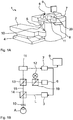
- Fig. 1 shows an ophthalmic laser treatment device 1 for vision correction using laser radiation.
- the treatment device 1 comprises a support device 2 for a patient in the form of a couch and a treatment laser 3 with optics for positioning and focusing the laser beam in the region of a treatment position at which an eye of the patient can be placed. It further comprises a positioning device 4, which carries the couch 2 and can move it linearly in all three spatial directions.
- a microscope beam path is coupled, which allows the practitioner on a viewing eyepiece 6, the visual control of the treatment progress.
- the treatment device 1 comprises a computer ("computer") as a control unit 7 with a keyboard 8 and a monitor as a display 9.
- the ophthalmological device 1 is controlled by the control unit 7.
- the laser 3 is, for example, a femtosecond laser, so that both a flap or a lateral extraction cut and a lenticle can be cut with the same laser.
- the treatment head 5 has, at its end facing the couch 2, a contact element 10 in the form of a contact glass, which touches the eye of the patient during treatment and fixes it spatially relative to the treatment device 1. During the irradiation process, the laser radiation is focused through the contact element 10 into the eye of the patient.
- the contact element 10 may be, for example, plan or anatomically curved on the eye side.
- an excimer laser may be arranged. If only an excimer laser is used, a contact element 10 can be dispensed with. When using an excimer laser, a motion tracking system is useful, which tracks the treatment laser 3 during the irradiation event of any eye movements of the patient.
- FIG. 1B are schematic and greatly simplified in terms of the optical structure of the coupled beam paths of the treatment laser 3, the microscope 6, the detection device 11 and the light source 12 are shown.
- the detection device 11 is designed as a camera, with which the eye A of the patient by two beam splitters 13, 14 and the contact glass 10, which is here still spaced from the eye A, is added.
- an observation beam path 15 extends from the eye A through the contact lens 10 and both beam splitters 13 and 14 to the camera 11.
- the image recorded by means of the camera 11 is transmitted to the computer 7.
- the beam splitter 13 serves to be able to observe the eye A microscopically via the observation eyepiece 6.
- Treatment laser radiation L from the laser 3 to the eye A can be conducted via the beam splitter 14 when the latter is spatially fixed by means of the contact glass 10 in order to carry out the correction of defective vision desired here.
- the light source 12 emits preferably exclusively infrared radiation, since in this case the pupil can open wide and also a high-contrast video recording of the pupil, especially in very dark irises, can be done. However, the light source 12 can also emit additional or alternative visible light. In particular, the visible spectral component can be switched off by means of a filter (not shown). The light of the light source 12 is reflected by a further beam splitter 19, for example in the microscope beam path.
- the video image of the camera 11 is analyzed by the evaluation unit 20. For this purpose, it performs a pupil recognition and displays at least one geometric characteristic, for example, pupil margin, centroid, best fit or best ellipse fit, on the monitor 9 and / or in the eyepiece 6 to the operator in overlay with the video image.
- the evaluation unit 20 performs a pupil recognition and displays at least one geometric characteristic, for example, pupil margin, centroid, best fit or best ellipse fit, on the monitor 9 and / or in the eyepiece 6 to the operator in overlay with the video image.
- a geometric characteristic with at least one treatment parameter, for example the lenticule position, the location and shape of the correction zone of the lenticule, the lenticule diameter, the marginal incision angle, the flap diameter, the flap center, the position of the flap hinge or the angle of the hinge, and / or a system parameter, such as the center of the treatment area, and determines a deviation from a given ideal case and outputs it on the monitor 9.
- a treatment parameter for example the lenticule position, the location and shape of the correction zone of the lenticule, the lenticule diameter, the marginal incision angle, the flap diameter, the flap center, the position of the flap hinge or the angle of the hinge, and / or a system parameter, such as the center of the treatment area
- a degree of overlap between the structure to be generated or at least the refractive corrective portion of the structure and the optical zone and a shift between the center of the pupil as the exemplary reference point and the center point determines the structure to be generated.
- This can be used to control the positioning device 4 so that the couch 2 and thus the eye A of lying on the couch 2 patient can be brought into a predetermined desired position relative to the contact glass 10.
- the displacement may be determined instead of the center of the pupil with any other ophthalmic characteristic by identifying and locating it in the captured image.
- the determination of the shift is on WO 2008/055604 A1 referenced, there in particular Fig. 3 and the related explanations. Expediently, image acquisition and identification as well as localization of the characteristic take place repeatedly in order to be able to take into account changes in the position of the eye. This also applies to the determination of the instantaneous degree of overlap.
- the areas can be determined, for example, by counting picture elements (pixels) in digitized images, for example the intersection pixel, which lies both within the determined pupil edge curve and within the correction zone of the surgical structure.
- the deviation of the centers of gravity of the correction zone and the pupil surface can be used, which permits a statement about the overlap reserve (additional coverage of the correction zone beyond the pupil surface).
- the accuracy of the comparison between treatment parameters and characteristic geometric sizes of the video image can be further improved by additionally adjusting the scaling of the video image and / or the superimposed visualized treatment parameters.
- the scaling ensures a better match of the geometric match of the metric of the coordinate systems to be compared.
- an evaluation of the deviation can take place, in particular from the point of view of whether the current position does not exceed a predetermined threshold value for the decentering and / or does not fall below a predetermined threshold value for the overlap of the optical zone with the structure to be produced.
- the evaluation unit 20 which is for example a software module of the control unit 7, displays, for example, the respectively last recorded image with marking of the recognized characteristic, here the pupil edge, with superposition of the structure to be generated on the monitor 9.
- the structure to be generated and the marking of the recognized characteristic can also be reflected in the microscope beam path, so that the operator perceives these decision aids superimposed directly on the image of the eye A. He can thereby directly perceive the degree of overlap himself.
- an automatic reaction of the device can be initiated, for example a compensation of the detected displacement.
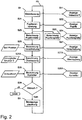
- Fig. 2 the exemplary sequence of a method for motion control in the form of a flow chart is shown schematically.
- the steps are largely the same as in WO 2008/055604 A1 described, wherein the display data in steps S11, S22, S24 and S27 are displayed simultaneously.
- the detected pupil and the determined displacement are superimposed on the video image on the same scale and next to this, the remaining data is superimposed.
- steps S26A, S27A and S28A are performed, which will be explained below.
- the structure to be generated is also superimposed on the video image in the context of the overlap display step S27A.
- the display can take place additionally or alternatively in the eyepiece 6, wherein the video image in the eyepiece 6 is omitted, since the optical image is available there.
- step S26A the instantaneous degree of overlap between the structure S and the current optical zone of the eye A is determined and displayed on the basis of the recognized pupil as geometrical characteristic and the predetermined surgical structure S, for example by hatching the intersection of the surfaces projected into the video image Structure S and the detected pupil P.
- the degree of overlap may be used in the calculation of the correction in step S28 in comparison to a predetermined threshold.
- the threshold describes, for example, an overlap that can be achieved at least. If this can not be achieved by any movement, the procedure is aborted. Otherwise, the determined correction proposal is displayed in step S28A with the other data, for example, as a shift vector in the video image.
- a signal can also be output for the user.
- the signal can be haptic, optical or acoustic.
- a quantitative indication of the extent of the deviation found is provided, in particular a simultaneous video overlay of recognized pupil and expected treatment geometry, for example the lenticular diameter, the flap diameter, or the center points.
- the invention can also be used in excimer laser systems in which the change in shape of the cornea takes place by ablation of the cornea.
- the therapy device usually compensates for minor malpositions by subjecting the beam positioning with a deviation amount measured by motion tracking, but comparing the shape and / or size of the detected pupil in terms of shape and location with the surgical structure provided for execution - an ablation pattern in the excimer laser - can also be used in such treatment methods to improve treatment safety and treatment efficacy. Even then, it is sensible to forego illumination in the visible spectral range and use infrared illumination in order to correctly detect the optical zone effective at night vision of the patient.
- iris structures are used to compare the relative rotational position of the eye with similar information from diagnostic measurements, thus determining relative rotation and relative displacement relative to a diagnostic image (registration image).
- this information is used to perform a rotation and / or displacement of the treatment geometry such that the found relative rotation and / or displacement is compensated for diagnostic measurements.
- the recognized features of the eye are used to verify the identity of the eye to be treated (eye recognition) in comparison with known features of the planned patient's eye.
- the user receives an indication of the probability of error or the measure of identity found.
- Fig. 3 shows two variants of the centering of a lenticle as structure S to be generated, in subfigure 3A near the center of the photopic pupil P, in FIG Partial figure 3B near the center of the scotopic pupil P '. It can be seen that in case A lenticle and scotopic pupil P 'just overlap. The exact evaluation of these or similar situations succeeds the practitioner only in the time available to him, if the inventive solution is available to him.
Landscapes
- Health & Medical Sciences (AREA)
- Ophthalmology & Optometry (AREA)
- Heart & Thoracic Surgery (AREA)
- Vascular Medicine (AREA)
- Optics & Photonics (AREA)
- Surgery (AREA)
- Engineering & Computer Science (AREA)
- Biomedical Technology (AREA)
- Physics & Mathematics (AREA)
- Nuclear Medicine, Radiotherapy & Molecular Imaging (AREA)
- Life Sciences & Earth Sciences (AREA)
- Animal Behavior & Ethology (AREA)
- General Health & Medical Sciences (AREA)
- Public Health (AREA)
- Veterinary Medicine (AREA)
- Eye Examination Apparatus (AREA)
- Laser Surgery Devices (AREA)
Claims (9)
- Appareil (1) de traitement ophtalmologique au laser comprenant :- un laser thérapeutique (3), en particulier un laser à excimère ou un laser femtoseconde, visant à introduire de l'énergie dans une partie d'un oeil (A) d'un patient conformément à une structure chirurgicale (S) prédéfinie,- une source de lumière (5) visant à illuminer au moins la partie de l'oeil (A) et- un dispositif de détection (6) visant à recevoir une image (B) d'au moins la partie de l'oeil (A), caractérisé par une unité de traitement (20), laquelle est disposée afin de déterminer un degré d'un recouvrement momentané d'une zone optique (P) de l'oeil (A) et de la structure (S) ou d'au moins une partie de la structure (S) exerçant une correction de réfraction au moyen d'une image reçue (B).
- Appareil (1) de traitement ophtalmologique selon la revendication 1, dans lequel l'unité de traitement (20) destinée à la détermination d'un degré d'un recouvrement détermine une surface de la pupille (P) au moyen de l'image reçue (B) et une surface de la structure (S) ou au moins de la partie de la structure (S) exerçant une correction de réfraction et un recoupement des deux surfaces.
- Appareil (1) de traitement ophtalmologique selon la revendication 1 ou 2, dans lequel l'unité de traitement (20) est disposée afin d'identifier et de localiser un élément caractéristique de l'oeil (A), en particulier une pupille (P), dans l'image reçue et afin de déterminer un déplacement relatif entre un point de l'élément caractéristique et un point de la structure (S).
- Appareil (1) de traitement ophtalmologique selon la revendication précédente, dans lequel l'unité de traitement (20) fournit visuellement l'image reçue (B) en surimpression avec une représentation graphique de la structure (S) selon le déplacement déterminé.
- Appareil (1) de traitement ophtalmologique selon la revendication 2 et/ou la revendication 3, comprenant en outre un dispositif de placement (2) pour le patient et un dispositif de positionnement (4) afin de déplacer le dispositif de placement (2) et/ou le laser (3), dans lequel l'unité de traitement (20) commande le dispositif de positionnement (4) en fonction du degré de recouvrement déterminé entre la pupille (P) et la structure (S) et/ou le déplacement entre l'élément caractéristique et la structure (S).
- Appareil (1) de traitement ophtalmologique selon l'une des revendications précédentes, dans lequel l'unité de traitement (20) compare une valeur du degré déterminé avec une valeur seuil prédéfinie et émet un signal haptique et/ou visuel et/ou acoustique en fonction d'un résultat de la comparaison et/ou dans lequel l'unité de traitement (20) compare une valeur du degré déterminé avec une valeur seuil prédéfinie et effectue, en fonction d'un résultat de la comparaison, en particulier également en fonction d'un déplacement relatif, une irradiation de l'oeil (A) conformément à la structure (S), en particulier avec les deux valeurs de seuil identiques.
- Appareil (1) de traitement ophtalmologique selon l'une des revendications précédentes, comprenant un élément de contact (10) visant à fixer mécaniquement l'oeil (A).
- Appareil (1) de traitement ophtalmologique selon l'une des revendications précédentes, dans lequel l'unité de traitement (20) est disposée de façon à effectuer la détermination du degré d'un recouvrement momentané avant et/ou après la fixation mécanique.
- Dispositif selon l'une des revendications précédentes, dans lequel la structure chirurgicale comporte un centre de symétrie, lequel est libre de positions à irradier.
Applications Claiming Priority (2)
| Application Number | Priority Date | Filing Date | Title |
|---|---|---|---|
| DE102010012616A DE102010012616A1 (de) | 2010-03-20 | 2010-03-20 | Ophthalmologische Laser-Behandlungseinrichtung und Betriebsverfahren für eine solche |
| PCT/EP2011/001319 WO2011116900A1 (fr) | 2010-03-20 | 2011-03-17 | Dispositif ophtalmologique de traitement par laser |
Publications (2)
| Publication Number | Publication Date |
|---|---|
| EP2549964A1 EP2549964A1 (fr) | 2013-01-30 |
| EP2549964B1 true EP2549964B1 (fr) | 2018-08-15 |
Family
ID=44169115
Family Applications (1)
| Application Number | Title | Priority Date | Filing Date |
|---|---|---|---|
| EP11712169.9A Active EP2549964B1 (fr) | 2010-03-20 | 2011-03-17 | Dispositif ophtalmologique de traitement par laser |
Country Status (4)
| Country | Link |
|---|---|
| US (2) | US8858540B2 (fr) |
| EP (1) | EP2549964B1 (fr) |
| DE (1) | DE102010012616A1 (fr) |
| WO (1) | WO2011116900A1 (fr) |
Families Citing this family (13)
| Publication number | Priority date | Publication date | Assignee | Title |
|---|---|---|---|---|
| US20130060241A1 (en) * | 2010-04-27 | 2013-03-07 | Daniel S. Haddad | Dynamic real time active pupil centroid compensation |
| DE102011083928A1 (de) | 2011-09-30 | 2013-04-04 | Carl Zeiss Meditec Ag | Behandlungsvorrichtung zur operativen Fehlsichtigkeitskorrektur eines Auges, Verfahren zum Erzeugen von Steuerdaten dafür und Verfahren zur operativen Fehlsichtigkeitskorrektur eines Auges |
| DE102015002729A1 (de) * | 2015-02-27 | 2016-09-01 | Carl Zeiss Meditec Ag | Ophthalmologische Lasertherapievorrichtung und Verfahren zur Erzeugung cornealer Zugangsschnitte |
| NZ773818A (en) | 2015-03-16 | 2022-07-29 | Magic Leap Inc | Methods and systems for diagnosing and treating health ailments |
| KR20220040511A (ko) | 2016-04-08 | 2022-03-30 | 매직 립, 인코포레이티드 | 가변 포커스 렌즈 엘리먼트들을 가진 증강 현실 시스템들 및 방법들 |
| IL268630B2 (en) | 2017-02-23 | 2023-09-01 | Magic Leap Inc | Display system with variable power reflector |
| CN112804974B (zh) * | 2018-09-20 | 2024-03-22 | 卡尔蔡司医疗技术股份公司 | 在眼睛内部中产生切口 |
| CN110200585B (zh) * | 2019-07-03 | 2022-04-12 | 南京博视医疗科技有限公司 | 一种基于眼底成像技术的激光束控制系统及其方法 |
| DE102019121731A1 (de) * | 2019-08-13 | 2021-02-18 | Carl Zeiss Meditec Ag | Verfahren zur Überwachung einer Funktionalität einer Vorrichtung für die refraktive Chirurgie eines Auges, Steuereinheit und Vorrichtung für die refraktive Chirurgie eines Auges |
| DE102019213735A1 (de) * | 2019-09-10 | 2021-03-11 | Carl Zeiss Meditec Ag | Augenchirurgische Behandlungsvorrichtung |
| DE102020110041A1 (de) * | 2020-04-09 | 2021-10-14 | Precitec Optronik Gmbh | Verfahren zur Bestimmung der Lage eines Flap-Schnittes auf einer Cornea und des zu dem Flap gehörigen Hinges sowie eine Vorrichtung zur Durchführung eines solchen Verfahrens |
| DE102022134511A1 (de) | 2022-12-22 | 2024-06-27 | Schwind Eye-Tech-Solutions Gmbh | Verfahren zum Bereitstellen von Steuerdaten mit einem zentrierten Korrekturprofil für die Behandlung einer Hornhaut |
| DE102023123242A1 (de) | 2023-08-29 | 2025-03-06 | Carl Zeiss Meditec Ag | Ophthalmisches lasersystem und verfahren zur visualisierung eines patientenauges |
Citations (3)
| Publication number | Priority date | Publication date | Assignee | Title |
|---|---|---|---|---|
| WO1999044492A1 (fr) * | 1998-03-04 | 1999-09-10 | Visx, Incorporated | Procede et systeme de traitement laser de la presbytie avec utilisation d'une image decentree |
| US20020049431A1 (en) * | 2000-10-20 | 2002-04-25 | Smith Michael J. | Method of correcting corneal refraction not aligned with the pupil center |
| US20030120266A1 (en) * | 2001-12-03 | 2003-06-26 | Masanao Fujieda | Ophthalmic apparatus and corneal surgery apparatus |
Family Cites Families (21)
| Publication number | Priority date | Publication date | Assignee | Title |
|---|---|---|---|---|
| US6267756B1 (en) | 1986-03-08 | 2001-07-31 | G. Rodenstock Instrumente Gmbh | Apparatus for the observation and the treatment of the eye using a laser |
| US5620436A (en) * | 1994-09-22 | 1997-04-15 | Chiron Technolas Gmbh Ophthalmologische Systeme | Method and apparatus for providing precise location of points on the eye |
| US7892226B2 (en) | 1995-03-20 | 2011-02-22 | Amo Development, Llc. | Method of corneal surgery by laser incising a contoured corneal flap |
| US5801807A (en) * | 1995-08-08 | 1998-09-01 | Nikon Corporation | Ophthalmic illumination device having adjustable transmittance member and microscope for operation using the same |
| US6159202A (en) * | 1995-09-29 | 2000-12-12 | Nidex Co., Ltd. | Corneal surgery apparatus |
| ES2199095T3 (es) * | 1999-10-21 | 2007-03-16 | Technolas Gmbh Ophthalmologische Systeme | Reconocimiento y seguimiento del iris para el tratamiento optico. |
| US6899707B2 (en) * | 2001-01-29 | 2005-05-31 | Intralase Corp. | Applanation lens and method for ophthalmic surgical applications |
| US20050117118A1 (en) * | 2001-10-05 | 2005-06-02 | David Miller | Digital ophthalmic workstation |
| JP3916482B2 (ja) | 2002-02-27 | 2007-05-16 | 株式会社ニデック | 眼科装置 |
| WO2003102498A1 (fr) * | 2002-05-30 | 2003-12-11 | Visx, Inc. | Poursuite de la position et de l'orientation en torsion de l'oeil |
| EP1758531A1 (fr) * | 2004-04-09 | 2007-03-07 | Roger F. Steinert | Systeme laser de correction de la vue |
| US7780653B2 (en) * | 2004-09-20 | 2010-08-24 | Hovanesian John A | Methods and apparatus for vision correction |
| US7662148B2 (en) | 2004-11-12 | 2010-02-16 | Technolas Perfect Vision Gmbh | Systems and methods for intrastromal scanning patterns |
| US7815631B2 (en) * | 2004-11-30 | 2010-10-19 | Alcon Refractivehorizons, Inc. | Eye registration system for refractive surgery and associated methods |
| DE102006053098A1 (de) | 2006-11-10 | 2008-05-15 | Carl Zeiss Meditec Ag | Ophthalmologische Vorrichtung und ophthalmologisches Verfahren zum Positionieren eines Auges eines Patienten in einer vorbestimmten Soll-Position |
| DE102006056711B4 (de) | 2006-11-30 | 2019-09-19 | Carl Zeiss Meditec Ag | Vorrichtung zum Erzeugen einer Korrekturschnittfläche in der Hornhaut eines Auges zur Fehlsichtigkeitskorrektur sowie Kontaktelement für eine solche Vorrichtung |
| WO2008098381A1 (fr) * | 2007-02-14 | 2008-08-21 | Ziemer Holding Ag | Dispositif ophthalmologique pour la dissolution du tissu oculaire |
| DE102007060008A1 (de) * | 2007-12-13 | 2009-06-18 | Technolas Gmbh Ophthalmologische Systeme | Bestimmung und Überwachumg von Laserenergie |
| DE102007055924B4 (de) * | 2007-12-21 | 2009-11-26 | Carl Zeiss Surgical Gmbh | Verfahren zur Ermittlung charakteristischer Eigenschaften und/oder der Position charakteristischer Augenbestandteile |
| US8444632B2 (en) * | 2008-11-05 | 2013-05-21 | Carl Zeiss Meditec Ag | Method of performing refractive laser eye surgery centered along the visual axis of a human eye |
| US9492322B2 (en) * | 2009-11-16 | 2016-11-15 | Alcon Lensx, Inc. | Imaging surgical target tissue by nonlinear scanning |
-
2010
- 2010-03-20 DE DE102010012616A patent/DE102010012616A1/de active Pending
-
2011
- 2011-03-17 WO PCT/EP2011/001319 patent/WO2011116900A1/fr not_active Ceased
- 2011-03-17 US US13/635,999 patent/US8858540B2/en active Active
- 2011-03-17 EP EP11712169.9A patent/EP2549964B1/fr active Active
-
2014
- 2014-09-11 US US14/483,515 patent/US20150005752A1/en not_active Abandoned
Patent Citations (3)
| Publication number | Priority date | Publication date | Assignee | Title |
|---|---|---|---|---|
| WO1999044492A1 (fr) * | 1998-03-04 | 1999-09-10 | Visx, Incorporated | Procede et systeme de traitement laser de la presbytie avec utilisation d'une image decentree |
| US20020049431A1 (en) * | 2000-10-20 | 2002-04-25 | Smith Michael J. | Method of correcting corneal refraction not aligned with the pupil center |
| US20030120266A1 (en) * | 2001-12-03 | 2003-06-26 | Masanao Fujieda | Ophthalmic apparatus and corneal surgery apparatus |
Also Published As
| Publication number | Publication date |
|---|---|
| EP2549964A1 (fr) | 2013-01-30 |
| US20150005752A1 (en) | 2015-01-01 |
| US20130072916A1 (en) | 2013-03-21 |
| US8858540B2 (en) | 2014-10-14 |
| WO2011116900A1 (fr) | 2011-09-29 |
| DE102010012616A1 (de) | 2011-09-22 |
Similar Documents
| Publication | Publication Date | Title |
|---|---|---|
| EP2549964B1 (fr) | Dispositif ophtalmologique de traitement par laser | |
| EP2729099B1 (fr) | Dispositif et procédé pour un système de traitement chirurgical oculaire assisté par un laser | |
| EP2337534B1 (fr) | Dispositif, procédé et programme de commande de chirurgie laser, notamment réfractive, en ophtalmologie | |
| EP1404265B9 (fr) | Dispositif permettant de representer une zone d'operation lors d'operations par laser. | |
| DE3688792T2 (de) | Gerät zur Auswertung und Korrektur von Brechungsfehlern des Auges. | |
| EP1985269B1 (fr) | Dispositif, procédé et programme de commande pour la chirurgie réfractive | |
| EP2306949B1 (fr) | Dispositif de chirurgie laser, notamment réfractive, en ophtalmologie | |
| WO2021069220A1 (fr) | Agencement destiné à la vitréolyse au laser basée sur l'oct | |
| EP2042078A2 (fr) | Procédé de détermination d'intervalles au niveau de la section avant de l'ýil | |
| EP3010390B1 (fr) | Système de détection de données de position d'au moins un élément dans la région antérieure d'un oeil | |
| DE102019219122A1 (de) | Positioniereinrichtung | |
| EP4225236A1 (fr) | Procédé de centrage d'une lentille de contact et système laser de chirurgie réfractive | |
| DE102013105738A1 (de) | Laserbehandlungsvorrichtung für die Refraktivchirurgie | |
| EP1200026B1 (fr) | Dispositif de traitement ophtalmologique des yeux par faisceau lumineux de fixation | |
| EP4216889A1 (fr) | Ensemble pour traitement laser d'opacités oculaires | |
| DE102006053098A1 (de) | Ophthalmologische Vorrichtung und ophthalmologisches Verfahren zum Positionieren eines Auges eines Patienten in einer vorbestimmten Soll-Position | |
| DE102009030464B4 (de) | Lasergerät und Verfahren, insbesondere Betriebsverfahren für ein Lasergerät, zur Erstellung von Bestrahlungssteuerdaten für einen gepulsten Laser | |
| DE102015217849A1 (de) | Systeme und Verfahren für eine lasergestützte Augenbehandlung | |
| DE102019219123A1 (de) | Beobachtungseinrichtung | |
| DE102019213734A1 (de) | Augenchirurgische Behandlungsvorrichtung | |
| DE102022121079A1 (de) | Refraktives chirurgisches lasersystem und verfahren zum ermitteln eines abstands zwischen einem kontaktglas und einem patientenauge | |
| EP4574110A1 (fr) | Dispositif de traitement de la rétine d'un il | |
| DE102011075734A1 (de) | Lasergerät zur Augentherapie |
Legal Events
| Date | Code | Title | Description |
|---|---|---|---|
| PUAI | Public reference made under article 153(3) epc to a published international application that has entered the european phase |
Free format text: ORIGINAL CODE: 0009012 |
|
| 17P | Request for examination filed |
Effective date: 20121018 |
|
| AK | Designated contracting states |
Kind code of ref document: A1 Designated state(s): AL AT BE BG CH CY CZ DE DK EE ES FI FR GB GR HR HU IE IS IT LI LT LU LV MC MK MT NL NO PL PT RO RS SE SI SK SM TR |
|
| DAX | Request for extension of the european patent (deleted) | ||
| GRAP | Despatch of communication of intention to grant a patent |
Free format text: ORIGINAL CODE: EPIDOSNIGR1 |
|
| STAA | Information on the status of an ep patent application or granted ep patent |
Free format text: STATUS: GRANT OF PATENT IS INTENDED |
|
| INTG | Intention to grant announced |
Effective date: 20170927 |
|
| GRAJ | Information related to disapproval of communication of intention to grant by the applicant or resumption of examination proceedings by the epo deleted |
Free format text: ORIGINAL CODE: EPIDOSDIGR1 |
|
| STAA | Information on the status of an ep patent application or granted ep patent |
Free format text: STATUS: REQUEST FOR EXAMINATION WAS MADE |
|
| GRAP | Despatch of communication of intention to grant a patent |
Free format text: ORIGINAL CODE: EPIDOSNIGR1 |
|
| STAA | Information on the status of an ep patent application or granted ep patent |
Free format text: STATUS: GRANT OF PATENT IS INTENDED |
|
| INTC | Intention to grant announced (deleted) | ||
| INTG | Intention to grant announced |
Effective date: 20180228 |
|
| GRAS | Grant fee paid |
Free format text: ORIGINAL CODE: EPIDOSNIGR3 |
|
| GRAA | (expected) grant |
Free format text: ORIGINAL CODE: 0009210 |
|
| STAA | Information on the status of an ep patent application or granted ep patent |
Free format text: STATUS: THE PATENT HAS BEEN GRANTED |
|
| RIN1 | Information on inventor provided before grant (corrected) |
Inventor name: BISCHOFF, MARK Inventor name: STOBRAWA, GREGOR |
|
| AK | Designated contracting states |
Kind code of ref document: B1 Designated state(s): AL AT BE BG CH CY CZ DE DK EE ES FI FR GB GR HR HU IE IS IT LI LT LU LV MC MK MT NL NO PL PT RO RS SE SI SK SM TR |
|
| REG | Reference to a national code |
Ref country code: CH Ref legal event code: EP Ref country code: GB Ref legal event code: FG4D Free format text: NOT ENGLISH Ref country code: AT Ref legal event code: REF Ref document number: 1028875 Country of ref document: AT Kind code of ref document: T Effective date: 20180815 |
|
| REG | Reference to a national code |
Ref country code: IE Ref legal event code: FG4D Free format text: LANGUAGE OF EP DOCUMENT: GERMAN |
|
| REG | Reference to a national code |
Ref country code: DE Ref legal event code: R096 Ref document number: 502011014596 Country of ref document: DE |
|
| REG | Reference to a national code |
Ref country code: NL Ref legal event code: MP Effective date: 20180815 |
|
| REG | Reference to a national code |
Ref country code: LT Ref legal event code: MG4D |
|
| PG25 | Lapsed in a contracting state [announced via postgrant information from national office to epo] |
Ref country code: GR Free format text: LAPSE BECAUSE OF FAILURE TO SUBMIT A TRANSLATION OF THE DESCRIPTION OR TO PAY THE FEE WITHIN THE PRESCRIBED TIME-LIMIT Effective date: 20181116 Ref country code: NO Free format text: LAPSE BECAUSE OF FAILURE TO SUBMIT A TRANSLATION OF THE DESCRIPTION OR TO PAY THE FEE WITHIN THE PRESCRIBED TIME-LIMIT Effective date: 20181115 Ref country code: IS Free format text: LAPSE BECAUSE OF FAILURE TO SUBMIT A TRANSLATION OF THE DESCRIPTION OR TO PAY THE FEE WITHIN THE PRESCRIBED TIME-LIMIT Effective date: 20181215 Ref country code: RS Free format text: LAPSE BECAUSE OF FAILURE TO SUBMIT A TRANSLATION OF THE DESCRIPTION OR TO PAY THE FEE WITHIN THE PRESCRIBED TIME-LIMIT Effective date: 20180815 Ref country code: SE Free format text: LAPSE BECAUSE OF FAILURE TO SUBMIT A TRANSLATION OF THE DESCRIPTION OR TO PAY THE FEE WITHIN THE PRESCRIBED TIME-LIMIT Effective date: 20180815 Ref country code: FI Free format text: LAPSE BECAUSE OF FAILURE TO SUBMIT A TRANSLATION OF THE DESCRIPTION OR TO PAY THE FEE WITHIN THE PRESCRIBED TIME-LIMIT Effective date: 20180815 Ref country code: LT Free format text: LAPSE BECAUSE OF FAILURE TO SUBMIT A TRANSLATION OF THE DESCRIPTION OR TO PAY THE FEE WITHIN THE PRESCRIBED TIME-LIMIT Effective date: 20180815 Ref country code: NL Free format text: LAPSE BECAUSE OF FAILURE TO SUBMIT A TRANSLATION OF THE DESCRIPTION OR TO PAY THE FEE WITHIN THE PRESCRIBED TIME-LIMIT Effective date: 20180815 Ref country code: BG Free format text: LAPSE BECAUSE OF FAILURE TO SUBMIT A TRANSLATION OF THE DESCRIPTION OR TO PAY THE FEE WITHIN THE PRESCRIBED TIME-LIMIT Effective date: 20181115 |
|
| PG25 | Lapsed in a contracting state [announced via postgrant information from national office to epo] |
Ref country code: LV Free format text: LAPSE BECAUSE OF FAILURE TO SUBMIT A TRANSLATION OF THE DESCRIPTION OR TO PAY THE FEE WITHIN THE PRESCRIBED TIME-LIMIT Effective date: 20180815 Ref country code: AL Free format text: LAPSE BECAUSE OF FAILURE TO SUBMIT A TRANSLATION OF THE DESCRIPTION OR TO PAY THE FEE WITHIN THE PRESCRIBED TIME-LIMIT Effective date: 20180815 Ref country code: HR Free format text: LAPSE BECAUSE OF FAILURE TO SUBMIT A TRANSLATION OF THE DESCRIPTION OR TO PAY THE FEE WITHIN THE PRESCRIBED TIME-LIMIT Effective date: 20180815 |
|
| PG25 | Lapsed in a contracting state [announced via postgrant information from national office to epo] |
Ref country code: EE Free format text: LAPSE BECAUSE OF FAILURE TO SUBMIT A TRANSLATION OF THE DESCRIPTION OR TO PAY THE FEE WITHIN THE PRESCRIBED TIME-LIMIT Effective date: 20180815 Ref country code: PL Free format text: LAPSE BECAUSE OF FAILURE TO SUBMIT A TRANSLATION OF THE DESCRIPTION OR TO PAY THE FEE WITHIN THE PRESCRIBED TIME-LIMIT Effective date: 20180815 Ref country code: CZ Free format text: LAPSE BECAUSE OF FAILURE TO SUBMIT A TRANSLATION OF THE DESCRIPTION OR TO PAY THE FEE WITHIN THE PRESCRIBED TIME-LIMIT Effective date: 20180815 Ref country code: RO Free format text: LAPSE BECAUSE OF FAILURE TO SUBMIT A TRANSLATION OF THE DESCRIPTION OR TO PAY THE FEE WITHIN THE PRESCRIBED TIME-LIMIT Effective date: 20180815 Ref country code: ES Free format text: LAPSE BECAUSE OF FAILURE TO SUBMIT A TRANSLATION OF THE DESCRIPTION OR TO PAY THE FEE WITHIN THE PRESCRIBED TIME-LIMIT Effective date: 20180815 Ref country code: IT Free format text: LAPSE BECAUSE OF FAILURE TO SUBMIT A TRANSLATION OF THE DESCRIPTION OR TO PAY THE FEE WITHIN THE PRESCRIBED TIME-LIMIT Effective date: 20180815 |
|
| REG | Reference to a national code |
Ref country code: DE Ref legal event code: R097 Ref document number: 502011014596 Country of ref document: DE |
|
| PG25 | Lapsed in a contracting state [announced via postgrant information from national office to epo] |
Ref country code: SK Free format text: LAPSE BECAUSE OF FAILURE TO SUBMIT A TRANSLATION OF THE DESCRIPTION OR TO PAY THE FEE WITHIN THE PRESCRIBED TIME-LIMIT Effective date: 20180815 Ref country code: DK Free format text: LAPSE BECAUSE OF FAILURE TO SUBMIT A TRANSLATION OF THE DESCRIPTION OR TO PAY THE FEE WITHIN THE PRESCRIBED TIME-LIMIT Effective date: 20180815 Ref country code: SM Free format text: LAPSE BECAUSE OF FAILURE TO SUBMIT A TRANSLATION OF THE DESCRIPTION OR TO PAY THE FEE WITHIN THE PRESCRIBED TIME-LIMIT Effective date: 20180815 |
|
| PLBE | No opposition filed within time limit |
Free format text: ORIGINAL CODE: 0009261 |
|
| STAA | Information on the status of an ep patent application or granted ep patent |
Free format text: STATUS: NO OPPOSITION FILED WITHIN TIME LIMIT |
|
| 26N | No opposition filed |
Effective date: 20190516 |
|
| PG25 | Lapsed in a contracting state [announced via postgrant information from national office to epo] |
Ref country code: SI Free format text: LAPSE BECAUSE OF FAILURE TO SUBMIT A TRANSLATION OF THE DESCRIPTION OR TO PAY THE FEE WITHIN THE PRESCRIBED TIME-LIMIT Effective date: 20180815 |
|
| PG25 | Lapsed in a contracting state [announced via postgrant information from national office to epo] |
Ref country code: MC Free format text: LAPSE BECAUSE OF FAILURE TO SUBMIT A TRANSLATION OF THE DESCRIPTION OR TO PAY THE FEE WITHIN THE PRESCRIBED TIME-LIMIT Effective date: 20180815 |
|
| REG | Reference to a national code |
Ref country code: CH Ref legal event code: PL |
|
| PG25 | Lapsed in a contracting state [announced via postgrant information from national office to epo] |
Ref country code: LU Free format text: LAPSE BECAUSE OF NON-PAYMENT OF DUE FEES Effective date: 20190317 |
|
| REG | Reference to a national code |
Ref country code: BE Ref legal event code: MM Effective date: 20190331 |
|
| PG25 | Lapsed in a contracting state [announced via postgrant information from national office to epo] |
Ref country code: CH Free format text: LAPSE BECAUSE OF NON-PAYMENT OF DUE FEES Effective date: 20190331 Ref country code: IE Free format text: LAPSE BECAUSE OF NON-PAYMENT OF DUE FEES Effective date: 20190317 Ref country code: LI Free format text: LAPSE BECAUSE OF NON-PAYMENT OF DUE FEES Effective date: 20190331 |
|
| PG25 | Lapsed in a contracting state [announced via postgrant information from national office to epo] |
Ref country code: BE Free format text: LAPSE BECAUSE OF NON-PAYMENT OF DUE FEES Effective date: 20190331 |
|
| PG25 | Lapsed in a contracting state [announced via postgrant information from national office to epo] |
Ref country code: TR Free format text: LAPSE BECAUSE OF FAILURE TO SUBMIT A TRANSLATION OF THE DESCRIPTION OR TO PAY THE FEE WITHIN THE PRESCRIBED TIME-LIMIT Effective date: 20180815 |
|
| PG25 | Lapsed in a contracting state [announced via postgrant information from national office to epo] |
Ref country code: PT Free format text: LAPSE BECAUSE OF FAILURE TO SUBMIT A TRANSLATION OF THE DESCRIPTION OR TO PAY THE FEE WITHIN THE PRESCRIBED TIME-LIMIT Effective date: 20181215 Ref country code: MT Free format text: LAPSE BECAUSE OF FAILURE TO SUBMIT A TRANSLATION OF THE DESCRIPTION OR TO PAY THE FEE WITHIN THE PRESCRIBED TIME-LIMIT Effective date: 20180815 |
|
| REG | Reference to a national code |
Ref country code: AT Ref legal event code: MM01 Ref document number: 1028875 Country of ref document: AT Kind code of ref document: T Effective date: 20190317 |
|
| PG25 | Lapsed in a contracting state [announced via postgrant information from national office to epo] |
Ref country code: AT Free format text: LAPSE BECAUSE OF NON-PAYMENT OF DUE FEES Effective date: 20190317 |
|
| PG25 | Lapsed in a contracting state [announced via postgrant information from national office to epo] |
Ref country code: CY Free format text: LAPSE BECAUSE OF FAILURE TO SUBMIT A TRANSLATION OF THE DESCRIPTION OR TO PAY THE FEE WITHIN THE PRESCRIBED TIME-LIMIT Effective date: 20180815 |
|
| PG25 | Lapsed in a contracting state [announced via postgrant information from national office to epo] |
Ref country code: HU Free format text: LAPSE BECAUSE OF FAILURE TO SUBMIT A TRANSLATION OF THE DESCRIPTION OR TO PAY THE FEE WITHIN THE PRESCRIBED TIME-LIMIT; INVALID AB INITIO Effective date: 20110317 |
|
| PG25 | Lapsed in a contracting state [announced via postgrant information from national office to epo] |
Ref country code: MK Free format text: LAPSE BECAUSE OF FAILURE TO SUBMIT A TRANSLATION OF THE DESCRIPTION OR TO PAY THE FEE WITHIN THE PRESCRIBED TIME-LIMIT Effective date: 20180815 |
|
| P01 | Opt-out of the competence of the unified patent court (upc) registered |
Effective date: 20230525 |
|
| PGFP | Annual fee paid to national office [announced via postgrant information from national office to epo] |
Ref country code: GB Payment date: 20260324 Year of fee payment: 16 |
|
| PGFP | Annual fee paid to national office [announced via postgrant information from national office to epo] |
Ref country code: DE Payment date: 20260319 Year of fee payment: 16 |
|
| PGFP | Annual fee paid to national office [announced via postgrant information from national office to epo] |
Ref country code: FR Payment date: 20260320 Year of fee payment: 16 |