EP2559544B1 - Dispositif et procédé de déformation d'ébauches en plastique en conteneurs en plastique dotés de coussins de pression - Google Patents
Dispositif et procédé de déformation d'ébauches en plastique en conteneurs en plastique dotés de coussins de pression Download PDFInfo
- Publication number
- EP2559544B1 EP2559544B1 EP12179848.2A EP12179848A EP2559544B1 EP 2559544 B1 EP2559544 B1 EP 2559544B1 EP 12179848 A EP12179848 A EP 12179848A EP 2559544 B1 EP2559544 B1 EP 2559544B1
- Authority
- EP
- European Patent Office
- Prior art keywords
- blow mould
- blow
- carrier shell
- shell part
- mould carrier
- Prior art date
- Legal status (The legal status is an assumption and is not a legal conclusion. Google has not performed a legal analysis and makes no representation as to the accuracy of the status listed.)
- Active
Links
Images


Classifications
-
- B—PERFORMING OPERATIONS; TRANSPORTING
- B29—WORKING OF PLASTICS; WORKING OF SUBSTANCES IN A PLASTIC STATE IN GENERAL
- B29D—PRODUCING PARTICULAR ARTICLES FROM PLASTICS OR FROM SUBSTANCES IN A PLASTIC STATE
- B29D22/00—Producing hollow articles
- B29D22/003—Containers for packaging, storing or transporting, e.g. bottles, jars, cans, barrels, tanks
-
- B—PERFORMING OPERATIONS; TRANSPORTING
- B29—WORKING OF PLASTICS; WORKING OF SUBSTANCES IN A PLASTIC STATE IN GENERAL
- B29C—SHAPING OR JOINING OF PLASTICS; SHAPING OF MATERIAL IN A PLASTIC STATE, NOT OTHERWISE PROVIDED FOR; AFTER-TREATMENT OF THE SHAPED PRODUCTS, e.g. REPAIRING
- B29C49/00—Blow-moulding, i.e. blowing a preform or parison to a desired shape within a mould; Apparatus therefor
- B29C49/42—Component parts, details or accessories; Auxiliary operations
- B29C49/42414—Treatment of preforms, e.g. cleaning or spraying water for improved heat transfer
- B29C49/42416—Purging or cleaning the preforms
- B29C49/42418—Purging or cleaning the preforms for sterilizing
-
- B—PERFORMING OPERATIONS; TRANSPORTING
- B29—WORKING OF PLASTICS; WORKING OF SUBSTANCES IN A PLASTIC STATE IN GENERAL
- B29C—SHAPING OR JOINING OF PLASTICS; SHAPING OF MATERIAL IN A PLASTIC STATE, NOT OTHERWISE PROVIDED FOR; AFTER-TREATMENT OF THE SHAPED PRODUCTS, e.g. REPAIRING
- B29C49/00—Blow-moulding, i.e. blowing a preform or parison to a desired shape within a mould; Apparatus therefor
- B29C49/42—Component parts, details or accessories; Auxiliary operations
- B29C49/48—Moulds
- B29C2049/4856—Mounting, exchanging or centering moulds or parts thereof
- B29C2049/4864—Fixed by a special construction to the mould half carriers, e.g. using insulating material between the mould and the mould half carrier
-
- B—PERFORMING OPERATIONS; TRANSPORTING
- B29—WORKING OF PLASTICS; WORKING OF SUBSTANCES IN A PLASTIC STATE IN GENERAL
- B29C—SHAPING OR JOINING OF PLASTICS; SHAPING OF MATERIAL IN A PLASTIC STATE, NOT OTHERWISE PROVIDED FOR; AFTER-TREATMENT OF THE SHAPED PRODUCTS, e.g. REPAIRING
- B29C2949/00—Indexing scheme relating to blow-moulding
- B29C2949/07—Preforms or parisons characterised by their configuration
- B29C2949/0715—Preforms or parisons characterised by their configuration the preform having one end closed
-
- B—PERFORMING OPERATIONS; TRANSPORTING
- B29—WORKING OF PLASTICS; WORKING OF SUBSTANCES IN A PLASTIC STATE IN GENERAL
- B29C—SHAPING OR JOINING OF PLASTICS; SHAPING OF MATERIAL IN A PLASTIC STATE, NOT OTHERWISE PROVIDED FOR; AFTER-TREATMENT OF THE SHAPED PRODUCTS, e.g. REPAIRING
- B29C33/00—Moulds or cores; Details thereof or accessories therefor
- B29C33/30—Mounting, exchanging or centering
-
- B—PERFORMING OPERATIONS; TRANSPORTING
- B29—WORKING OF PLASTICS; WORKING OF SUBSTANCES IN A PLASTIC STATE IN GENERAL
- B29C—SHAPING OR JOINING OF PLASTICS; SHAPING OF MATERIAL IN A PLASTIC STATE, NOT OTHERWISE PROVIDED FOR; AFTER-TREATMENT OF THE SHAPED PRODUCTS, e.g. REPAIRING
- B29C49/00—Blow-moulding, i.e. blowing a preform or parison to a desired shape within a mould; Apparatus therefor
- B29C49/02—Combined blow-moulding and manufacture of the preform or the parison
- B29C49/06—Injection blow-moulding
-
- B—PERFORMING OPERATIONS; TRANSPORTING
- B29—WORKING OF PLASTICS; WORKING OF SUBSTANCES IN A PLASTIC STATE IN GENERAL
- B29C—SHAPING OR JOINING OF PLASTICS; SHAPING OF MATERIAL IN A PLASTIC STATE, NOT OTHERWISE PROVIDED FOR; AFTER-TREATMENT OF THE SHAPED PRODUCTS, e.g. REPAIRING
- B29C49/00—Blow-moulding, i.e. blowing a preform or parison to a desired shape within a mould; Apparatus therefor
- B29C49/28—Blow-moulding apparatus
- B29C49/30—Blow-moulding apparatus having movable moulds or mould parts
- B29C49/36—Blow-moulding apparatus having movable moulds or mould parts rotatable about one axis
Definitions
- the present invention relates to an apparatus and a method for forming plastic preforms into plastic containers.
- Such devices and methods have been known for a long time from the prior art.
- blow molds or blow moldings are arranged on carriers and these carriers can be unfolded and folded, wherein in a closed state of the blow mold plastic preforms are expanded inside this blow mold, in particular by application of compressed air to plastic containers.
- two mold carrier shells are provided, on each of which the blow-molded parts are fixed. These mold carrier shells are in turn arranged on a blow mold carrier or a blow mold carrier part.
- the document US-A-2004202745 discloses an apparatus and a method according to the preambles of claims 1 and 7.
- Increasing production figures are important parameters, in particular for the customers of the equipment in question here.
- the present invention is therefore based on the object of reducing downtimes, in particular downtimes due to changes of cloth.
- Another object of the present invention is to provide a quick-change system which can be operated without an additional tool.
- Another object is to achieve a simple and quick handling, without the need for a manual operation of locks is required.
- An inventive device for forming plastic preforms to plastic containers is disclosed by the claim 1.
- the holding device has an actuating body which extends through an opening formed in a wall of the blow mold carrier shell part and / or an opening formed in a wall of a blow mold carrier part, this actuating body being movable relative to the wall and wherein a first holding element for holding the blow molded part is arranged on the actuating body is.
- the actuating body or at least a portion of this actuating body extends through the wall of the Blasformitatischalenteils and / or the wall of Blasformziteils through.
- the actuating body or at least a portion of this actuating body extends through the wall of the Blasformitatischalenteils and / or the wall of Blasformziteils through.
- the actuating body or at least a portion of this actuating body extends through the wall of the Blasformitatis through.
- a corresponding (for example pneumatically) actuated actuating system is therefore advantageously integrated in this system essentially completely in the blow mold carrier shell.
- a connection for example a pneumatic connection, can be installed directly over the blow mold carrier shell part in an advantageous blow mold carrier shell part in the mold carrier halves.
- the actuating body may be, for example, a piston element which, as mentioned above, is pneumatically movable.
- this piston or the actuator body performs the function of a clamping hook.
- the clamping hook represents a preferred embodiment of the above-mentioned holding element and advantageously takes both the task of a grid position during insertion of the blow molding and on the other hand, the task of clamping the blow molded part true.
- a connection for a flowable medium and in particular for a gaseous medium is arranged on at least one Blasformitatischalenteil.
- the actuating body on a druckstoffbeetzmacherbaren piston can be arranged in a cylinder system.
- the holding element - preferably fixed - arranged.
- the opening in the wall is arranged in a recess formed in the wall of the wall.
- This wall may extend outward in a radial direction of the closed blow mold. Through this recess, the insertion of the respective blow molding is facilitated.
- a second retaining element is fastened to the blow molding part, which acts together with the first retaining element for fastening the blow molding part to the blow mold carrier shell part.
- a grip element for example, be screwed, in which engages said first support member. Due to the interaction of these two holding elements, the blow molding is attached to the Blasformitatischalenteil.
- the second holding element is rigidly connected to the blow molding.
- the holding element arranged on the blow mold carrier shell part engages behind the holding element arranged on the blow mold part.
- the second holding element projects with respect to a wall of the blow-molded part.
- the second holding element may be arranged on a carrier, and a portion of the carrier may protrude with respect to the said wall of the blow-molded part. This projecting portion can engage in the above-mentioned recess in the wall of the Blasformitatischalenteils.
- a relative movement of the blow molding relative to the Blasformitatischalen matter only in a relaxed state of the holding device is possible, but not in a fixed or mounted state.
- this relative movement is a rotary movement of the blow molded part with respect to a predetermined axis of rotation relative to the blow mold carrier shell part.
- a holder for a blow mold carrier is also arranged on the blow mold carrier shell part.
- the present invention is further directed to a method of attaching blow moldings to blow mold carrier shell parts according to claim 7.
- the blow mold part After being applied to the blow mold carrier shell part, the blow mold part is moved relative to the blow mold carrier shell part such that a first holding element arranged on the blow mold carrier shell part and a second holding element arranged on the blow mold part engage in one another.
- the first holding element arranged on the blow mold carrier shell part is moved in a further direction in order to lock the blow molded part to the blow mold carrier shells, the movement of the first holding element being produced by an actuating body which extends at least partially through a wall of the blow mold carrier shell part.
- a pressure pad arrangement is arranged between at least one blow mold carrier part and the blow mold part arranged on this blow mold carrier, a pressure chamber or a pressure pad device of this pressure pad arrangement being able to be acted upon by a flowable pressure medium, by at least one blow mold carrier part and by a force acting between the blow mold carrier part and the blow mold part to push apart at this arranged blow molding.
- the pressure pad arrangement is formed such that the force acting between the Blasformsammlungteil and the blow molding part has a first partial force in a first predetermined - and preferably spatially definable or definable - and preferably spatially definable or delimitable - in the circumferential direction of the blow molding acts as a second partial force acting in a second predetermined range in the circumferential direction of the blow molding, wherein the first region and the second region are spaced apart and the directions of the first partial force and the second partial force in an angle different from each other by 0 degrees
- the given areas in which the partial forces act therefore, preferably result from a particular geometric shape of the pressure pad assembly.
- the arrangement of the blow molded part on the blow mold carrier part means that this blow molded part is arranged at least indirectly, ie, if necessary, for further elements on the blow mold carrier part.
- the blow molding is in turn on a Blasformitatischale, hereinafter also briefly arranged as a carrier shell and this carrier shell is preferably disposed on the Blasformangoteil, said pressure pad assembly between the Blasformitatiteil and the said carrier shell is formed.
- the prior art is usually between the Blasformitatiteil and the blow molding only one arranged uniform pressure pad, which can be acted upon with compressed air. Accordingly, when the pressure pad is acted upon, a resultant force acts only in one direction, so that in this resultant direction the blow mold and the blow mold carrier are forced apart.
- the flowable medium with which the pressure pad is acted upon is, in particular, a gaseous medium, preferably air and, if necessary, sterile air.
- the position and design of the pressure pad is designed so that the deformation in the mold carrier and in the (form) carrier shell is reduced. More specifically, the forces applied by the pressure pad are divided into at least two components that act at different angles on the carrier shell or blow mold, thereby reducing the risk of tension during the expansion process.
- the two partial forces are independent of each other and particularly preferably also - in particular with regard to their sizes - independently adjustable.
- no force acts (apart from a vekotriell from the partial forces together) force or only one compared to the partial forces significantly lower force, which forces apart the blow molded part and the Blasformangoteil.
- the device for forming plastic preforms also has a loading device, which acts on the plastic preforms during the expansion process with a gaseous medium and in particular with compressed air in order to expand them.
- the device preferably also has a stretching rod which stretches the plastic preforms in the longitudinal direction thereof during the expansion process.
- a locking device which locks the mold carrier parts together, in particular during the expansion process.
- This lock can engage cam-controlled and designed in this way be that at the beginning of the expansion process and also in the course of the expansion process, the two mold carrier parts are locked together.
- the design with the two partial forces allows a more uniform pressing of the two blow moldings together.
- the device has only such a pressure pad arrangement on one of the two mold carriers.
- the angle between the direction of the first partial force and the direction of the second partial force between 10 ° and 170 °, preferably between 20 ° and 160 °, preferably between 30 ° and 150 °, preferably between 45 ° and 135 ° , preferably between 60 ° and 120 ° and more preferably between 75 ° and 105 °.
- the pressure pad is arranged in a V-arrangement, so that the two forces are in the said angle to each other.
- the carrier shell is held on the Blasformarmeteil via a positive retention, so that a fixed position of said pressure pad is achieved.
- the pressure pad arrangement has a first pressure pad device and a second pressure pad device which are at least partially or partially separated from one another and are preferably completely separated from one another.
- said pressure pad devices By means of said pressure pad devices, the abovementioned two forces may optionally be applied to the blow mold or carrier shell independently of one another. However, it would also be possible that only a pressure pad device is provided, but this is designed such that the two forces mentioned above arise. This can be achieved, for example, by a web within a single pressure pad device, which ensures that no or only small forces are exerted in the circumferential direction of the blow mold in a central region between the two partial forces mentioned.
- An at least partial separation of the pressure pad devices is understood in particular to mean that these pressure pad devices can be connected to one another via a connecting section, but that connecting section is not along an entire side edge of at least one pressure pad device but only along a portion of such a side edge, which is preferably less than 50% of the side edge, preferably less than 30% of the side edge, preferably less than 20% of the side edge.
- the pressure pad devices are advantageously connected to one another via a connecting section which extends to less than 20% of the circumference of at least one of the two pressure pad devices, preferably to less than 10% of the circumference, preferably to less than 5% of the circumference scope.
- the apparatus has a first supply means for supplying the flowable medium to the first pressure pad means, as well as a second feeding means separate therefrom, for feeding the flowable medium to the second pressure pad means. In this way, a different control of the two pressure pad devices is possible.
- the supply channels for the two pressure pad devices can be completely separated from each other, but it would also be possible that the two pressure pad devices via a common port, the flowable medium, ie the compressed air is supplied.
- the pressure pad arrangement has an encircling sealing device, which supports the space acted upon by the flowable pressure medium, ie. H. the pressure chamber, delimits, and this sealing device abuts against a flat wall area.
- the sealing device In the prior art, three-dimensionally applied sealing devices are commonly used, i. H. in particular sealing devices, which also extend along a curved portion of the carrier shell or the blow mold or blow mold carrier. In this embodiment, it is proposed that the sealing device only along a plane d. H. a straight plane and thus extends only in the two-dimensional area. In this way, an improved sealing effect is possible.
- the pressure pad arrangement is arranged between the blow mold carrier part and a carrier shell holding the blow mold part.
- This carrier shell can be designed such that the blow molded part is detachably designed by this carrier shell.
- the device has a holding device for holding the blow molding on the Blasformanii, and this holding device is arranged in a circumferential direction of the blow mold between areas of the pressure pad assembly.
- a preferably with respect to the pressure pad assembly arrangement of the holding device is provided which, for example, if only one pressure pad device is provided, may be provided on a corresponding limiting web.
- the holding device is arranged between the first pressure pad device and the second pressure pad device.
- no force is exerted in the direction of the blow mold by the pressure pad itself.
- a blow mold which has two blow moldings arranged in a mutually moveable manner, which form a cavity in a closed state of the blow mold, in the interior of which the plastic preforms are imparted by application of a flowable plastic preform Medium and in particular be expanded with compressed air to the plastic containers.
- the first blow molding is arranged on a first Blasformitatiteil and the second blow molding on a second Blasformitatiteil.
- the first blow mold carrier part is moved relative to the second blow mold carrier part for opening and closing the blow mold.
- a pressure chamber or a pressure device of this pressure pad assembly is acted upon by a flowable pressure medium to at least by a force acting between the Blasformitatiteil and the blow molding force to force apart a blow mold carrier part and the blow mold part arranged thereon.
- the pressure pad assembly is formed such that the force acting between the blow mold carrier member and the blow molding member has a first parting force acting in a first predetermined region in the circumferential direction of the blow molding member, such as a second component force acting in a second predetermined region in the circumferential direction of Blow molding, wherein the first region and the second region are spaced apart and the directions of the first partial force and the second partial force in a 0 degrees different angle to each other.
- the pressure pad assembly is designed so that at least two partial forces are provided, which act on the blow molding or a blow molding holding carrier shell.
- a holding force acting between the blow molding part and the blow mold carrier part acts in the circumferential direction of the blow mold between the first part force and the second part force.
- FIG. 1 shows a schematic representation of a plant for producing plastic containers according to the prior art.
- This system 50 has a heating device 30 in which plastic preforms 10 are heated.
- these plastic preforms 10 are guided by means of a transport device 34, such as a revolving chain, through this heater 30 and thereby heated with a plurality of heating elements 31.
- This heating device 30 is followed by a transfer unit 36, which transfers the preforms 10 to a sterilization device 32.
- This sterilization device 32 in this case likewise has a transport wheel 37 and sterilizing elements can be arranged on this transport wheel 37 or even stationary. In this area, for example, a sterilization by hydrogen peroxide gas or by electromagnetic radiation is possible. In particular, an internal sterilization of the preforms is carried out in this area.
- the reference numeral 20 denotes in its entirety a clean room, the outer boundaries are indicated here by the dotted line L.
- the clean room 20 is arranged not only in the region of the transport wheel 2 and filling device 40, but possibly already starts in the area of the heating device 30, the sterilization device 32, the plastic preform supply and / or the plastic preform production. It can be seen that this clean room 20 begins in the area of the sterilization unit 32. In this area, lock devices can be provided to introduce the plastic preforms into the clean room 20 without too much gas flowing inside the clean room and thus being lost.
- the clean room is, as indicated by the dashed line L, adapted to the outer shape of the individual plant components. In this way, the volume of the clean room can be reduced.
- the reference numeral 1 denotes in its entirety a forming device in which a plurality of blowing stations or forming stations 8 is arranged on a transport wheel 2, wherein only one of these blowing stations 8 is shown here. With these blowing stations 8, the plastic preforms 10 are expanded to containers 10a. Although not shown in detail here, not the entire area of the transport device 2 is located within the clean room 20, but the clean room 20 or insulator is effectively implemented as a mini-isolator within the entire device. Thus, it would be possible for the clean room to be channel-like, at least in the area of the forming device 1.
- the reference numeral 22 refers to a feeding device which transfers the preforms to the forming device 1 and the reference numeral 24 to a discharge device which discharges the produced plastic containers 20 from the forming device 1. It can be seen that the clean room 20 in the area of the feed device 22 and the discharge device 24 each have recesses which receive these devices 22, 24. In this way, a transfer of the plastic preforms 10 to the forming device 1 and a takeover of the plastic containers 10a of the forming device 1 can be achieved in a particularly advantageous manner.
- the expanded plastic containers are transferred to a filling device 40 and then from this filling device 40 via a further transport unit 44 removed.
- the filling device it would also be possible for the entire filling device 40 with, for example, a reservoir for a beverage, not to be arranged completely inside the clean room 6, but here too only those areas where the containers are actually kept.
- the filling device could be constructed in a similar manner as the device 1 for forming plastic preforms 10th
- the clean room 20 in the area of the device 1 is reduced to a minimum possible area, namely substantially to the blowing stations 8 itself.
- This small-sized design of the clean room 20 makes it easier and faster to produce a clean room at all and also to maintain sterility in the operating phase is less expensive. Also, less sterile air is needed, resulting in smaller filter units and also the risk of uncontrolled vortex formation is reduced.
- FIG. 2 shows a detailed representation of the device 1 in the region of a blowing station 8.
- a plurality of such blowing stations 8 is rotatably moved with a transport device 2 and a support about an axis X.
- the blowing station 8 is as in FIG. 2 can be seen within the clean room 20, which is here channel-like out.
- This clean room 20 is completed by a movable side wall 19 and a lid 17 integrally formed with this side wall 19. This side wall 19 and the cover 17 thereby rotate with the blowing station 8.
- the reference numeral 18 refers to a further wall which limits the clean room 16.
- This wall 18 is here an outer wall, which is arranged stationary.
- a sealing device 25 is provided between the cover 17 and the wall 18, which seals the mutually movable elements 17 and 18 against each other, for example, as mentioned above, using a water lock.
- the lower portion of the wall 18 is fixedly and sealingly arranged on a bottom 13.
- a support 26 is provided, which also moves in rotation and on which in turn a holding device 23 is provided, which holds the blowing station 8.
- the reference numeral 11 refers to a follower which can be actuated by a guide cam 9 to open and close the blow station on its way through the clean room 6, in particular to insert the plastic preform in the blow station and to remove it again.
- a guide curve 9 is also arranged within the clean room 20.
- the transport device 2 may also have further elements, which are arranged above the clean room 20.
- the carrier 26 is fixedly arranged on a holding body 29 and this holding body is in turn movable relative to the bottom 13.
- the reference numeral 27 refers to a further sealing device, which causes a sealing of the mutually movable portions 13 and 29 in this area.
- the reference numeral 5 refers to a stretching rod which is movable with respect to the blowing station in order to stretch the plastic preforms 10 in their longitudinal direction.
- a carriage 12 is arranged on the lid 17, on the other hand, the stretch rod in the direction Y is movable.
- the reference numeral 21 refers to a further holder for this carriage 12 of the stretch rod. 5
- the reference symbol U denotes the (non-sterile) environment of the clean room 20.
- the reference symbol 28 designates a carrier for supporting a bottom mold, which likewise forms part of the blow mold 4. This carrier is also movable in the direction Y.
- the reference numeral 55 refers to a sterilization device, which is preferably arranged here in the interior of the clean room 20 and for sterilizing the individual transformation stations or components of these conversion stations 8 is used.
- This sterilization device 55 can act on the conversion stations 8, for example, with hydrogen peroxide or other sterilizing agent.
- the sterilization device 55 can be arranged stationary and the transformation stations can move relative to this sterilization device 55.
- This sterilization device or loading device 55 may be located on the transport wheel 2 or on the stationary wall 18 or may be arranged generally stationary and consist of nozzles o similar.
- the blow molds (not shown) are disposed inside the blow mold carriers 6. More precisely, two Blasformabomaschine can be arranged, which are pivotable relative to each other and each holding a blow mold. By this pivoting process, the blow molds for introducing plastic preforms and for removing finished blown containers can be opened. These blow mold carriers and blow molds are likewise arranged inside the clean room.
- the transport device 2 or the carrier has a C-shaped outer circumference, which also partially forms the outer walls of the clean room.
- this C - shaped clean room wall rotates here with the transport device 2, ie the blowing wheel.
- the lower boundary of the clean room is spaced from the floor 13 and moves relative to the floor. In this way, the clean room can be made even smaller than in Fig.2 shown.
- This outer wall is advantageously arranged stationary.
- the in the Figures 1 and 2 The arrangement shown relates to a sterile blow molding arrangement. However, the present invention is also applicable to conventional or non-sterile blow molding machines. Also in FIG. 1 The system concept shown can be used for both sterile and non-sterile machines.
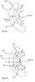
- Fig. 3a and 3b show two schematic representations to illustrate the problem underlying the invention and its solution.
- Fig. 3a shows the conditions according to the prior art
- a Blasformitatiteil 6a is provided on which a blow mold 4a (possibly. On a carrier shell) is arranged .. It would also be conceivable to attach the blow molds directly to the carrier.
- a pressure pad provided in the circumferential direction UR, which is formed between the two seal portions 182a and 182b. This pressure pad thus generates a resulting force Fres, which acts horizontally here.
- the small force arrows inside the blow molds refer to the forces that are created by the actual blowing process. This means that it can lead to tension and also to deformations of the blow mold or the Blasformitatischale in this way.
- Fig. 3b shows an embodiment of the invention.
- two pressure cushions spaced apart from each other by the circumferential seals 82, 84 are provided here, which in this case exert partial forces F1 and F2 which are arranged at the predetermined angle relative to one another on the blow mold 4a or the carrier shell for the blow mold.
- the reference numerals 82, 84 thus denote sealing devices which surround or form the two pressure pads. Due to the effect with two partial forces F1 and F2, an overall more uniform force effect can be exerted on the blow mold 4a or the carrier shell. These two areas B1 and B2 in which the partial forces act are spaced apart here in the circumferential direction UR of the blow mold.
- the angle a, under which the two forces F1 and F2 extend to each other, is advantageously in a range between 70 ° and 110 °.
- the circumferential direction is advantageously also a circumferential direction of the plastic preform or container to be expanded.
- the mentioned angle ⁇ is advantageously formed in a plane formed by the circumferential direction. This plane is advantageously perpendicular to a longitudinal direction of the plastic preform and is advantageously parallel to the plane of the figure of Fig. 3b
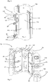
- FIG. 4 shows a perspective view of a blowing station according to the invention 8.
- This blow station 8 has two blow mold parts 4a, 4b, which are shown here in a closed state. Between these two blow mold parts 4a, 4b is the above-mentioned Cavity formed within which the plastic preforms are expanded to the plastic containers.
- blow molding 4a and accordingly also the blow molding 4b are here fixed to Blasformitatischaleniser 70a, 70b fixed, for example, clamped or screwed.
- These blow mold carrier shells 70a, 70b are in turn arranged on blow mold carrier parts 6a and 6b.
- Blasformlessness are pivotable relative to a common pivot axis 112 to open the blow mold and close.
- the reference numeral 92 refers to a first locking element in which engages a second locking element 94 for locking the blow mold during the expansion process.
- this second locking element 94 is pivotable with respect to a pivot shaft 105.
- the reference numeral 88 refers to fasteners which serve to fix the blow mold carrier cups 70a and 70b to the respective blow mold carrier members 6a, 6b.
- the reference numeral 110 designates a locking element which serves for fast locking and unlocking of the blow mold carrier shells 55a and 55b with respect to the associated blow mold carrier parts 6a and 6b.
- Fig. 5 shows a partial view of in Fig. 4 Device shown, ie, a Blasformitatiteil 6a with the Blaschtschalenteil arranged therein and the blow molding 4a.
- a connection 120 can also be seen here, via which a tempering medium, for example a heated liquid, can be supplied to the blow molding part 4a.
- Fig. 6 shows a representation of the blow mold carrier shells 70a, 70b. It can be seen that they have a polygonal outer circumference here, ie both carrier shell parts 70a and 70b each have four edges on their outer surfaces.
- Reference numerals 114 and 115 refer to surfaces of the blow mold carrier shells which in use are loaded by the pressure pad (not shown). The corresponding forces applied by the pressure pads here act essentially perpendicular to the two surfaces 114 and 115 Pressure pads are therefore also limited by the surfaces 114, 115 or sections of these surfaces. The surfaces are even or two-dimensional. The sealing means 82 and 84 abut against these surfaces.
- the reference numeral 116 refers to a holding member with which the blow moldings (not shown) are held on the blow mold carrier cups 70a, 70b.
- the reference numeral 118 denotes an engagement means, such as a claw, which holds the blow moldings in a closed state.
- this engagement means is pivotable, so that the blow molding can be decoupled from the carrier shells on this pivoting process.
- Fig. 7 shows a further illustration of a Blasformsammlungteils 6a.
- the sealing devices 82, 84 which in each case form or limit the two pressure pad devices 62, 64.
- the reference numeral 102 again indicates the area disposed between these two pressure pads and serves to fix the mold carrier shell portion to the blow molding support portion 6a.
- the sealing means 82, 84 are here, as mentioned above, arranged in a planar region and thus formed two-dimensionally, which is easier to accomplish than a three-dimensional course, which extends for example on a curved wall.
- the reference numerals 72, 74 respectively denote feed means by means of which the area surrounded by the seal means 82 and thus forming the pressure pads 62, 64 is pressurized with compressed air so as to push apart the blow mold tray portion and the blow mold support portion 6a.
- Reference numerals 104 and 106 refer to passage openings through which the fastening means 88 can be guided.
- the reference numeral 113 again indicates a suspension on which the Blasformangoteil 6a is articulated so as to be pivotable in this way.
- the attachment means may include spring means 89 which provide a clamping force which contract the mold carrier tray 70a and the blow mold carrier member 6a
- Fig. 8 shows a plan view of the in Fig. 7 shown device.
- the reference numeral 82 again indicates the sealing device and the reference numeral 75 a holding device, by which the sealing device is held on the Blasformangoteil.
- This holding device 75 may be, for example, a plate which is screwed by one or more screws on the Blasformitatiteil 6 a and which clamps a portion of the circumferential sealing means 82.
- a (also circumferential) portion 82a of the sealing device 82 bears against the blow mold carrier shell (not shown).
- the sealing devices are advantageously made of an elastomer and preferably run in a plane.
- the reference numeral a / 2 denotes the angle formed between the right-hand pressure pad and a mid-perpendicular. The total angle between these two pressure angles accordingly corresponds to that of the angle a.
- the pressure pads were divided into two equal parts and placed in a V-shaped arrangement at an optimum angle.
- the above-mentioned form-fitting holder or the fastening means 88 also provide for a fixed position of the now simplified two-dimensional seal 82. More specifically, this fixed position can be generated by the holding device 75, which may be a plate, for example.
- Fig. 9 shows a further embodiment of the device according to the invention. It can be seen that here the area surrounded by the sealing device 82 is reduced and thus also the pressure pad 62 is reduced in size. Thus, here the pressure pad surface was changed by the change of the sealing device 82 and in this way it is possible to control the position of the force on the Blasformitatischalen and also the size of the force targeted. If desired, webs could also pass through the respective pressure pad means 62 in order to further split the forces.
- Fig. 10 shows a representation of a Blasformitatischalenteils 70a.
- This Blasformitatischalenteil 70a serves to receive a blow molding.
- the blow mold carrier shell part 70a has an inner wall 142, in which a (only partially) visible opening 144 is arranged.
- the said opening 144 is formed within a recess 148.
- Reference numeral 145 denotes an inclined surface, which is an insertion of a blow molding, as in Fig. 12 shown, relieved.
- Reference numerals 162 and 164 denote terminals for supplying a tempering agent to the blow mold carrier shell portion.
- the actuating body 140 can via the in Fig. 6 shown pneumatic connection 150 with a pneumatic means, for example with compressed air, to be moved.
- Fig. 11 shows an enlarged view of the coupling region in the recess 148.
- the holding member 152 has a semi-circular or V-shaped cross section 152a, with which it behind the projection 154a of in Fig. 13 shown second retaining element 154 can engage.
- a nose or a projection 168 is provided, which engages in a corresponding recess 172 which is arranged on the blow molding part 4a, to center the Blasformmbateil.
- the stopper 146 further serves for correct positioning of the blow molding part 4a in the blow mold carrier shell 70a. In this way, a displacement of the blow molding 4a with respect to the Blasformitatischalenteil 70a in the longitudinal direction LR is prevented.
- Fig. 12 shows a representation of a blow molding 4a.
- This blow molded part has here the second holding element 154, which cooperates with the first holding element 152.
- the reference numeral 157 refers to a peripheral wall of the blow molding 4a, which abuts in a mounted state on the wall 142 of the Blasformitatischalenteils. Due to this surface contact between the walls 142 and 157, a heat transfer is also possible, so that with the aid of the tempering connections 162 and 164, the blow-molded part 4 a can also be tempered indirectly.
- the holding element 154 has a projection 154 a, which serves in a mounted state blow molding a Blasformitatischalenteil that the solid support member 152 can not be moved relative to the second support member 154. Furthermore, it can be seen that the second holding element 154 protrudes with respect to the wall 157th is trained. The first holding element 152 can thus engage in the second holding element 154.
- the reference numerals 153 relate to fastening means, such as screws, which are recessed here with respect to the wall 157 and with which the retaining element 154 is arranged on the blow molding 4a.
- the reference numeral 163 denotes a further recess in the wall 157, which facilitates insertion of the first retaining element 152 into the second retaining element 154.
- the recess 163 extends at least also in the direction E in which, during assembly, the blow-molded part is moved or rotated relative to the blow-mold carrier shell part 70a, i. in particular in a circumferential direction of the blow molding 4a.
- Fig. 14 shows a sectional view of an attached to the Blasformitatischalenteil 70a blow mold part 4a, wherein also the total marked 138 holding device is recognizable.
- the movable relative to the Blasformitatischalenteil 70a actuator body 140 which serves to clamp the blow molding 4a to the Blasformitatischalenteil 70a.
- the actuating body (140) extends through the wall 142 of the Blasformterägerschalenteils 70 a.
- the first holding element 152 can be seen, which engages behind the arranged on the blow molding second holding element.
- the reference numeral 6a refers to the blow mold carrier part on which the blow mold carrier shell part 70a is arranged.
- Components of the holding device 138 also extend through a wall of the Blasformitatiteils 6a, more precisely through in Fig. 7 shown opening 104.
- Fig. 15 shows a sectional view of a holding device 138.
- the actuator body 140 is movable in the direction R, wherein this direction also represents a radial direction of the blow molds or of the container to be expanded.
- the actuating body 140 is thereby guided by the wall 142, through which it extends.
- Reference numeral 188 refers to a sealing device.
- a piston member 204 is arranged and also fixed.
- the piston member 204 is movably disposed opposite to a piston space 206 in the direction R. It can be seen that the first retaining element 152, which is formed here in one piece with the actuating body 140, engages behind the second retaining element 154. The second holding element 154 protrudes into the recess 148, which is formed in the wall 142 is, inside.
- the reference numeral 202 refers to a formed on the actuating element 146 stage, against which the piston member 204 is supported.
- Fig. 16 shows a perspective view of the holding device 138.
- a pneumatic medium eg compressed air are supplied.
- the reference numeral 212 refers to a circumferential sealing device which seals the piston chamber 206.
- An end portion of the actuating body 140 extends into a sleeve body 124. In this case, this sleeve body 124 is arranged in the direction R fixed to the actuating body 140.
- the reference numeral 122 denotes a cover device which is screwed to the blow mold carrier shell part 70a and covers the holding device 138. The sleeve body extends through this covering device 122.
- the reference numeral 214 refers to a piston plate.
- Fig. 17 shows a further illustration of a blow molding, on which for the purpose of illustration the actuating body 140 is arranged, wherein its (not visible) retaining element engages behind the second retaining element 154.
Landscapes
- Engineering & Computer Science (AREA)
- Mechanical Engineering (AREA)
- Manufacturing & Machinery (AREA)
- Physics & Mathematics (AREA)
- Thermal Sciences (AREA)
- Blow-Moulding Or Thermoforming Of Plastics Or The Like (AREA)
- Moulds For Moulding Plastics Or The Like (AREA)
Claims (7)
- Dispositif (1) de transformation d'ébauches en matière plastique (10) en récipients en matière plastique, comprenant un moule de soufflage (4), lequel comprend au moins deux parties de moule de soufflage (4a, 4b) montées mobiles l'une par rapport à l'autre, lesquelles, une fois le moule de soufflage (4) fermé, forment une cavité à l'intérieur de laquelle les ébauches en matière plastique (10) peuvent être mises en expansion par application d'un milieu fluide de manière à obtenir les récipients en matière plastique (10a), dans lequel la première partie de moule de soufflage (4a) est agencée de manière démontable sur une première partie de coque de support de moule de soufflage (70a) et la deuxième partie de moule de soufflage (4b) est agencée de manière démontable sur une deuxième partie de coque de support de moule de soufflage (70b) et la première partie de coque de support de moule de soufflage (70a) peut être déplacée par rapport à la deuxième partie de coque de support de moule de soufflage (70b) pour ouvrir et fermer le moule de soufflage (4), et dans lequel, pour retenir au moins une partie de moule de soufflage (4a, 4b) sur la partie de coque de support de moule de soufflage (70a, 70b) qui lui est associée, un système de retenue (138) est prévu, lequel comprend un corps d'actionnement (140) qui s'étend à travers une ouverture (144) ménagée dans une paroi (142) de la partie de coque de support de moule de soufflage (70a, 70b) et/ou d'une partie de support de moule de soufflage (6a, 6b), dans lequel ce corps d'actionnement (140) est mobile par rapport à la paroi (142) et dans lequel un premier élément de retenue (152) destiné à retenir la partie de moule de soufflage (4a, 4b) est agencé sur le corps d'actionnement (140),
caractérisé en ce que
le mouvement du corps d'actionnement (140) par rapport à la paroi (142) peut être produit par un milieu fluide, et en particulier de manière pneumatique, et au moins une partie de coque de support de moule de soufflage (70a) est agencée sur une partie de support de moule de soufflage (6a) et un ensemble tampon de pression est formé entre la partie de support de moule de soufflage (6) et la partie de coque de support de moule de soufflage (70a), dans lequel un deuxième élément de retenue (154) est fixé à la partie de moule de soufflage (4a, 4b) et coopère avec le premier élément de retenue pour fixer la partie de moule de soufflage (4a, 4b) à la partie de coque de support de moule de soufflage (70a, 70b) et, une fois la partie de moule de soufflage (4a, 4b) fixée à la partie de coque de support de moule de soufflage (70a, 70b), un élément de retenue (152, 154) enserre le deuxième élément de retenue (154, 152) par l'arrière. - Dispositif selon la revendication 1,
caractérisé en ce que
un raccord pour un milieu fluide est agencé sur au moins une partie de coque de support de moule de soufflage (70a, 70b). - Dispositif selon au moins l'une des revendications précédentes,
caractérisé en ce que
le corps d'actionnement (140) comprend un piston (152) pouvant être exposé à un milieu sous pression. - Dispositif selon au moins l'une des revendications précédentes,
caractérisé en ce que
l'ouverture (144) est agencée dans un évidement (148) de la paroi ménagé dans la paroi (142). - Dispositif selon la revendication 1,
caractérisé en ce que
le deuxième élément de retenue (154) fait saillie d'une paroi (162) de la partie de moule de soufflage (4a, 4b). - Dispositif selon la revendication 1,
caractérisé en ce que
dans au moins un état, malgré une insertion des éléments de retenue l'un dans l'autre, un mouvement relatif d'une partie de moule de soufflage (4a, 4b) par rapport à la partie de coque de support de moule de soufflage (70a, 70b) retenant cette partie de moule de soufflage (4a, 4b) est permis. - Procédé de fixation de parties de moule de soufflage (4a, 4b) à des parties de coque de support de moule de soufflage (70a, 70b), dans lequel la partie de moule de soufflage (4a, 4b) est appliquée sur la partie de coque de support de moule de soufflage (70a, 70b) dans un positionnement prédéfini et la partie de moule de soufflage (4a, 4b), une fois appliquée sur la partie de coque de support de moule de soufflage (70a, 70b), est déplacée par rapport à la partie de coque de support de moule de soufflage (70a, 70b), de telle manière qu'un premier élément de retenue (152) agencé sur la partie de coque de support de moule de soufflage et un deuxième élément de retenue (154) fixé à la partie de moule de soufflage (4a, 4b), lequel deuxième élément de retenue coopère avec le premier élément de retenue pour fixer la partie de moule de soufflage (4a, 4b) à la partie de coque de support de moule de soufflage (70a, 70b), parviennent en contact l'un avec l'autre, et immédiatement après, le premier élément de retenue (152) agencé sur la partie de coque de support de moule de soufflage est déplacé dans une autre direction, afin de bloquer la partie de moule de soufflage (4a, 4b) sur la partie de coque de support de moule de soufflage, et dans lequel le déplacement du premier élément de retenue (152) est produit par un corps d'actionnement (140) qui s'étend au moins en partie à travers une paroi (142) de la partie de coque de support de moule de soufflage (70a, 70b),
caractérisé en ce que
le corps d'actionnement (140) est déplacé par rapport à la paroi (142) par un milieu fluide et en particulier de manière pneumatique, dans lequel au moins une partie de coque de support de moule de soufflage (70a) est agencée sur une partie de support de moule de soufflage (6a) et un ensemble tampon de pression est formé entre la partie de support de moule de soufflage (6) et la partie de coque de support de moule de soufflage (70a) et, une fois la partie de moule de soufflage (4a, 4b) fixée à la partie de coque de support de moule de soufflage (70a, 70b), un élément de retenue (152, 154) enserre le deuxième élément de retenue (154, 152) par l'arrière.
Applications Claiming Priority (1)
| Application Number | Priority Date | Filing Date | Title |
|---|---|---|---|
| DE102011052863.6A DE102011052863B4 (de) | 2011-08-19 | 2011-08-19 | Vorrichtung zum Umformen von Kunststoffvorformlingen zu Kunststoffbehältnissen und Verfahren zum Befestigen von Blasformteilen an Blasformträgerschalenteilen |
Publications (3)
| Publication Number | Publication Date |
|---|---|
| EP2559544A2 EP2559544A2 (fr) | 2013-02-20 |
| EP2559544A3 EP2559544A3 (fr) | 2014-01-29 |
| EP2559544B1 true EP2559544B1 (fr) | 2018-06-13 |
Family
ID=46934388
Family Applications (1)
| Application Number | Title | Priority Date | Filing Date |
|---|---|---|---|
| EP12179848.2A Active EP2559544B1 (fr) | 2011-08-19 | 2012-08-09 | Dispositif et procédé de déformation d'ébauches en plastique en conteneurs en plastique dotés de coussins de pression |
Country Status (4)
| Country | Link |
|---|---|
| US (1) | US9457524B2 (fr) |
| EP (1) | EP2559544B1 (fr) |
| CN (1) | CN102950758B (fr) |
| DE (1) | DE102011052863B4 (fr) |
Families Citing this family (4)
| Publication number | Priority date | Publication date | Assignee | Title |
|---|---|---|---|---|
| DE102014107512B4 (de) | 2014-05-28 | 2016-02-25 | Krones Ag | Blasformeinrichtung mit vorspannbarer Befestigung für Blasformen |
| FR3038541B1 (fr) | 2015-07-08 | 2017-07-21 | Sidel Participations | Dispositif de moulage pour une machine de fabrication de recipients en matiere thermoplastique |
| ITUB20160870A1 (it) * | 2016-02-19 | 2017-08-19 | Sipa Progettazione Automaz | Stampo di soffiaggio |
| FR3053906B1 (fr) | 2016-12-12 | 2018-08-17 | Sidel Participations | Dispositif de moulage pour la mise en œuvre de procedes de moulage a chaud et de moulage a froid |
Citations (4)
| Publication number | Priority date | Publication date | Assignee | Title |
|---|---|---|---|---|
| US6099286A (en) * | 1998-05-29 | 2000-08-08 | Wentworth Mould And Die Company | Universal mold carrier with improved air flow compensation |
| DE60001269T2 (de) * | 1999-03-08 | 2004-01-22 | Sidel | Formeinheit die eine verbesserte formschliessklemmeinrichung aufweist und extrusionsblasformmaschine wo diese fromschliessklemmeinrichtung verwendet wird |
| DE202004011785U1 (de) * | 2004-07-27 | 2004-10-14 | Krones Ag | Blasformbehälter und Formblasmaschine |
| US20050142243A1 (en) * | 2003-12-30 | 2005-06-30 | Wentworth Mold Inc. | Air flow compensation for mold carrier |
Family Cites Families (8)
| Publication number | Priority date | Publication date | Assignee | Title |
|---|---|---|---|---|
| FR2659265B1 (fr) * | 1990-03-06 | 1992-06-26 | Sidel Sa | Procede de dispositif pour fabriquer des recipients en matieres thermoplastiques par soufflage ou etirage-soufflage. |
| DE20007429U1 (de) * | 2000-04-22 | 2001-05-23 | KRONES AG, 93073 Neutraubling | Blasform und Blasmaschine |
| FR2813231B1 (fr) | 2000-08-31 | 2003-05-09 | Sidel Sa | Unite de moulage comportant une chambre de compensation delimitee par une membrane, membrane pour une telle unite et machine munie d'une telle unite |
| CA2425972C (fr) | 2003-04-11 | 2010-06-01 | Wentworth Mold Inc. | Ensemble de coquilles de moulage a remplissage a chaud a transfert de chaleur reduit |
| FR2903933B1 (fr) | 2006-07-21 | 2008-10-03 | Sidel Participations | Dispositif de moulage pour la fabrication de recipients thermoplastiques |
| EP2263854B1 (fr) | 2008-12-19 | 2013-05-01 | Krones AG | Machine de formage par soufflage entraînée de manière électrique et le procédé |
| US8070470B2 (en) * | 2009-02-06 | 2011-12-06 | Wentworth Mold Ltd. | Mold assembly |
| DE102009050637B4 (de) | 2009-05-06 | 2019-06-19 | Krones Aktiengesellschaft | Blasformanordnung |
-
2011
- 2011-08-19 DE DE102011052863.6A patent/DE102011052863B4/de active Active
-
2012
- 2012-07-31 US US13/562,979 patent/US9457524B2/en active Active
- 2012-08-09 EP EP12179848.2A patent/EP2559544B1/fr active Active
- 2012-08-17 CN CN201210294766.6A patent/CN102950758B/zh active Active
Patent Citations (4)
| Publication number | Priority date | Publication date | Assignee | Title |
|---|---|---|---|---|
| US6099286A (en) * | 1998-05-29 | 2000-08-08 | Wentworth Mould And Die Company | Universal mold carrier with improved air flow compensation |
| DE60001269T2 (de) * | 1999-03-08 | 2004-01-22 | Sidel | Formeinheit die eine verbesserte formschliessklemmeinrichung aufweist und extrusionsblasformmaschine wo diese fromschliessklemmeinrichtung verwendet wird |
| US20050142243A1 (en) * | 2003-12-30 | 2005-06-30 | Wentworth Mold Inc. | Air flow compensation for mold carrier |
| DE202004011785U1 (de) * | 2004-07-27 | 2004-10-14 | Krones Ag | Blasformbehälter und Formblasmaschine |
Also Published As
| Publication number | Publication date |
|---|---|
| US9457524B2 (en) | 2016-10-04 |
| CN102950758B (zh) | 2016-03-16 |
| EP2559544A2 (fr) | 2013-02-20 |
| DE102011052863A1 (de) | 2013-02-21 |
| US20130193624A1 (en) | 2013-08-01 |
| DE102011052863B4 (de) | 2022-12-22 |
| CN102950758A (zh) | 2013-03-06 |
| EP2559544A3 (fr) | 2014-01-29 |
Similar Documents
| Publication | Publication Date | Title |
|---|---|---|
| EP2559545B1 (fr) | Dispositif et procédé moulage par soufflage d'ébauches en plastique en conteneurs en plastique doté d'un coussin de pression | |
| EP2495086B1 (fr) | Souffleuse dotée d'un verrouillage de moule de soufflage dans la salle stérile | |
| EP2382076B1 (fr) | Procédé et dispositif de moulage par soufflage de contenants | |
| EP3088161B1 (fr) | Procede et dispositif de chauffage destine au conditionnement thermique d'ebauches et machine de moulage par soufflage comprenant un tel dispositif | |
| WO2008106921A1 (fr) | Procédé et dispositif de moulage par soufflage de récipients | |
| EP2618986B1 (fr) | Procédé et dispositif de moulage par soufflage de récipients | |
| EP3055120B1 (fr) | Procédé et dispositif pour la production d'un récipient rempli de matière de remplissage | |
| EP3416803B1 (fr) | Disposition à pinces pour la manipulation de préformes et roue de transfert et machine de traitement de récipients présentant une telle disposition à pinces | |
| DE102005017540A1 (de) | Verfahren und Vorrichtung zur Blasformung von Behältern | |
| EP2559544B1 (fr) | Dispositif et procédé de déformation d'ébauches en plastique en conteneurs en plastique dotés de coussins de pression | |
| DE10354506A1 (de) | Vorrichtung zur Blasformung von Behältern | |
| DE102014107512B4 (de) | Blasformeinrichtung mit vorspannbarer Befestigung für Blasformen | |
| EP3571035B1 (fr) | Mandrin à changement rapide intégrant un serrage actif de préforme | |
| EP2913174B1 (fr) | Machine de formage par soufflage à centrage du fond de moule de soufflage | |
| EP4493387A1 (fr) | Machine de formage pour la mise en forme de préformes en récipients et procédé de fonctionnement d'une telle machine | |
| EP2694270B1 (fr) | Dispositif pour le moulage de recipients par soufflage | |
| EP3452265A1 (fr) | Dispositif de chauffage pour une machine de soufflage présentant une chaîne d'alimentation repliable | |
| EP3064334B1 (fr) | Procédé et dispositif de chauffage destiné à déterminer la température d'ébauches et machine de moulage par soufflage comprenant un tel dispositif | |
| EP1473139B1 (fr) | Procédé et appareil de formage de récipients par soufflage | |
| DE102005045942A1 (de) | Verfahren und Vorrichtung zur Blasformung von Behältern | |
| DE102014019722A1 (de) | Blasformeinrichtung mit vorspannbarer Befestigung für Blasformen | |
| EP2237941B1 (fr) | Procédé et dispositif de formage par soufflage de récipients | |
| EP3691857A1 (fr) | Moule en plusieurs parties pour la fabrication par moulage de récipients à poignée, station de moulage, roue de moulage et machine de moulage équipé d'un moule, procédé de fabrication d'un récipient à poignée et récipient fabriqué selon ce procédé |
Legal Events
| Date | Code | Title | Description |
|---|---|---|---|
| PUAI | Public reference made under article 153(3) epc to a published international application that has entered the european phase |
Free format text: ORIGINAL CODE: 0009012 |
|
| AK | Designated contracting states |
Kind code of ref document: A2 Designated state(s): AL AT BE BG CH CY CZ DE DK EE ES FI FR GB GR HR HU IE IS IT LI LT LU LV MC MK MT NL NO PL PT RO RS SE SI SK SM TR |
|
| AX | Request for extension of the european patent |
Extension state: BA ME |
|
| PUAL | Search report despatched |
Free format text: ORIGINAL CODE: 0009013 |
|
| AK | Designated contracting states |
Kind code of ref document: A3 Designated state(s): AL AT BE BG CH CY CZ DE DK EE ES FI FR GB GR HR HU IE IS IT LI LT LU LV MC MK MT NL NO PL PT RO RS SE SI SK SM TR |
|
| AX | Request for extension of the european patent |
Extension state: BA ME |
|
| RIC1 | Information provided on ipc code assigned before grant |
Ipc: B29C 49/42 20060101AFI20131220BHEP Ipc: B29C 49/48 20060101ALN20131220BHEP |
|
| 17P | Request for examination filed |
Effective date: 20140729 |
|
| RBV | Designated contracting states (corrected) |
Designated state(s): AL AT BE BG CH CY CZ DE DK EE ES FI FR GB GR HR HU IE IS IT LI LT LU LV MC MK MT NL NO PL PT RO RS SE SI SK SM TR |
|
| 17Q | First examination report despatched |
Effective date: 20160909 |
|
| RIC1 | Information provided on ipc code assigned before grant |
Ipc: B29C 49/42 20060101AFI20170929BHEP Ipc: B29C 49/48 20060101ALN20170929BHEP |
|
| RIC1 | Information provided on ipc code assigned before grant |
Ipc: B29C 49/42 20060101AFI20171027BHEP Ipc: B29C 49/48 20060101ALN20171027BHEP |
|
| GRAP | Despatch of communication of intention to grant a patent |
Free format text: ORIGINAL CODE: EPIDOSNIGR1 |
|
| RIC1 | Information provided on ipc code assigned before grant |
Ipc: B29C 49/48 20060101ALN20171124BHEP Ipc: B29C 49/42 20060101AFI20171124BHEP Ipc: B29C 49/06 20060101ALN20171124BHEP Ipc: B29C 33/30 20060101ALN20171124BHEP Ipc: B29C 49/36 20060101ALN20171124BHEP |
|
| INTG | Intention to grant announced |
Effective date: 20180102 |
|
| GRAS | Grant fee paid |
Free format text: ORIGINAL CODE: EPIDOSNIGR3 |
|
| GRAA | (expected) grant |
Free format text: ORIGINAL CODE: 0009210 |
|
| AK | Designated contracting states |
Kind code of ref document: B1 Designated state(s): AL AT BE BG CH CY CZ DE DK EE ES FI FR GB GR HR HU IE IS IT LI LT LU LV MC MK MT NL NO PL PT RO RS SE SI SK SM TR |
|
| REG | Reference to a national code |
Ref country code: GB Ref legal event code: FG4D Free format text: NOT ENGLISH |
|
| REG | Reference to a national code |
Ref country code: CH Ref legal event code: EP Ref country code: AT Ref legal event code: REF Ref document number: 1008008 Country of ref document: AT Kind code of ref document: T Effective date: 20180615 |
|
| REG | Reference to a national code |
Ref country code: IE Ref legal event code: FG4D Free format text: LANGUAGE OF EP DOCUMENT: GERMAN |
|
| REG | Reference to a national code |
Ref country code: DE Ref legal event code: R096 Ref document number: 502012012864 Country of ref document: DE Ref country code: FR Ref legal event code: PLFP Year of fee payment: 7 |
|
| REG | Reference to a national code |
Ref country code: NL Ref legal event code: MP Effective date: 20180613 |
|
| REG | Reference to a national code |
Ref country code: LT Ref legal event code: MG4D |
|
| PG25 | Lapsed in a contracting state [announced via postgrant information from national office to epo] |
Ref country code: ES Free format text: LAPSE BECAUSE OF FAILURE TO SUBMIT A TRANSLATION OF THE DESCRIPTION OR TO PAY THE FEE WITHIN THE PRESCRIBED TIME-LIMIT Effective date: 20180613 Ref country code: SE Free format text: LAPSE BECAUSE OF FAILURE TO SUBMIT A TRANSLATION OF THE DESCRIPTION OR TO PAY THE FEE WITHIN THE PRESCRIBED TIME-LIMIT Effective date: 20180613 Ref country code: LT Free format text: LAPSE BECAUSE OF FAILURE TO SUBMIT A TRANSLATION OF THE DESCRIPTION OR TO PAY THE FEE WITHIN THE PRESCRIBED TIME-LIMIT Effective date: 20180613 Ref country code: NO Free format text: LAPSE BECAUSE OF FAILURE TO SUBMIT A TRANSLATION OF THE DESCRIPTION OR TO PAY THE FEE WITHIN THE PRESCRIBED TIME-LIMIT Effective date: 20180913 Ref country code: FI Free format text: LAPSE BECAUSE OF FAILURE TO SUBMIT A TRANSLATION OF THE DESCRIPTION OR TO PAY THE FEE WITHIN THE PRESCRIBED TIME-LIMIT Effective date: 20180613 Ref country code: CY Free format text: LAPSE BECAUSE OF FAILURE TO SUBMIT A TRANSLATION OF THE DESCRIPTION OR TO PAY THE FEE WITHIN THE PRESCRIBED TIME-LIMIT Effective date: 20180613 Ref country code: BG Free format text: LAPSE BECAUSE OF FAILURE TO SUBMIT A TRANSLATION OF THE DESCRIPTION OR TO PAY THE FEE WITHIN THE PRESCRIBED TIME-LIMIT Effective date: 20180913 |
|
| PG25 | Lapsed in a contracting state [announced via postgrant information from national office to epo] |
Ref country code: GR Free format text: LAPSE BECAUSE OF FAILURE TO SUBMIT A TRANSLATION OF THE DESCRIPTION OR TO PAY THE FEE WITHIN THE PRESCRIBED TIME-LIMIT Effective date: 20180914 Ref country code: RS Free format text: LAPSE BECAUSE OF FAILURE TO SUBMIT A TRANSLATION OF THE DESCRIPTION OR TO PAY THE FEE WITHIN THE PRESCRIBED TIME-LIMIT Effective date: 20180613 Ref country code: LV Free format text: LAPSE BECAUSE OF FAILURE TO SUBMIT A TRANSLATION OF THE DESCRIPTION OR TO PAY THE FEE WITHIN THE PRESCRIBED TIME-LIMIT Effective date: 20180613 Ref country code: HR Free format text: LAPSE BECAUSE OF FAILURE TO SUBMIT A TRANSLATION OF THE DESCRIPTION OR TO PAY THE FEE WITHIN THE PRESCRIBED TIME-LIMIT Effective date: 20180613 |
|
| PG25 | Lapsed in a contracting state [announced via postgrant information from national office to epo] |
Ref country code: NL Free format text: LAPSE BECAUSE OF FAILURE TO SUBMIT A TRANSLATION OF THE DESCRIPTION OR TO PAY THE FEE WITHIN THE PRESCRIBED TIME-LIMIT Effective date: 20180613 |
|
| PG25 | Lapsed in a contracting state [announced via postgrant information from national office to epo] |
Ref country code: CZ Free format text: LAPSE BECAUSE OF FAILURE TO SUBMIT A TRANSLATION OF THE DESCRIPTION OR TO PAY THE FEE WITHIN THE PRESCRIBED TIME-LIMIT Effective date: 20180613 Ref country code: SK Free format text: LAPSE BECAUSE OF FAILURE TO SUBMIT A TRANSLATION OF THE DESCRIPTION OR TO PAY THE FEE WITHIN THE PRESCRIBED TIME-LIMIT Effective date: 20180613 Ref country code: IS Free format text: LAPSE BECAUSE OF FAILURE TO SUBMIT A TRANSLATION OF THE DESCRIPTION OR TO PAY THE FEE WITHIN THE PRESCRIBED TIME-LIMIT Effective date: 20181013 Ref country code: PL Free format text: LAPSE BECAUSE OF FAILURE TO SUBMIT A TRANSLATION OF THE DESCRIPTION OR TO PAY THE FEE WITHIN THE PRESCRIBED TIME-LIMIT Effective date: 20180613 Ref country code: EE Free format text: LAPSE BECAUSE OF FAILURE TO SUBMIT A TRANSLATION OF THE DESCRIPTION OR TO PAY THE FEE WITHIN THE PRESCRIBED TIME-LIMIT Effective date: 20180613 Ref country code: RO Free format text: LAPSE BECAUSE OF FAILURE TO SUBMIT A TRANSLATION OF THE DESCRIPTION OR TO PAY THE FEE WITHIN THE PRESCRIBED TIME-LIMIT Effective date: 20180613 |
|
| PG25 | Lapsed in a contracting state [announced via postgrant information from national office to epo] |
Ref country code: SM Free format text: LAPSE BECAUSE OF FAILURE TO SUBMIT A TRANSLATION OF THE DESCRIPTION OR TO PAY THE FEE WITHIN THE PRESCRIBED TIME-LIMIT Effective date: 20180613 |
|
| REG | Reference to a national code |
Ref country code: DE Ref legal event code: R097 Ref document number: 502012012864 Country of ref document: DE |
|
| PG25 | Lapsed in a contracting state [announced via postgrant information from national office to epo] |
Ref country code: MC Free format text: LAPSE BECAUSE OF FAILURE TO SUBMIT A TRANSLATION OF THE DESCRIPTION OR TO PAY THE FEE WITHIN THE PRESCRIBED TIME-LIMIT Effective date: 20180613 |
|
| REG | Reference to a national code |
Ref country code: CH Ref legal event code: PL |
|
| PLBE | No opposition filed within time limit |
Free format text: ORIGINAL CODE: 0009261 |
|
| STAA | Information on the status of an ep patent application or granted ep patent |
Free format text: STATUS: NO OPPOSITION FILED WITHIN TIME LIMIT |
|
| PG25 | Lapsed in a contracting state [announced via postgrant information from national office to epo] |
Ref country code: LU Free format text: LAPSE BECAUSE OF NON-PAYMENT OF DUE FEES Effective date: 20180809 Ref country code: LI Free format text: LAPSE BECAUSE OF NON-PAYMENT OF DUE FEES Effective date: 20180831 Ref country code: CH Free format text: LAPSE BECAUSE OF NON-PAYMENT OF DUE FEES Effective date: 20180831 |
|
| REG | Reference to a national code |
Ref country code: BE Ref legal event code: MM Effective date: 20180831 |
|
| 26N | No opposition filed |
Effective date: 20190314 |
|
| GBPC | Gb: european patent ceased through non-payment of renewal fee |
Effective date: 20180913 |
|
| REG | Reference to a national code |
Ref country code: IE Ref legal event code: MM4A |
|
| PG25 | Lapsed in a contracting state [announced via postgrant information from national office to epo] |
Ref country code: DK Free format text: LAPSE BECAUSE OF FAILURE TO SUBMIT A TRANSLATION OF THE DESCRIPTION OR TO PAY THE FEE WITHIN THE PRESCRIBED TIME-LIMIT Effective date: 20180613 Ref country code: SI Free format text: LAPSE BECAUSE OF FAILURE TO SUBMIT A TRANSLATION OF THE DESCRIPTION OR TO PAY THE FEE WITHIN THE PRESCRIBED TIME-LIMIT Effective date: 20180613 |
|
| PG25 | Lapsed in a contracting state [announced via postgrant information from national office to epo] |
Ref country code: IE Free format text: LAPSE BECAUSE OF NON-PAYMENT OF DUE FEES Effective date: 20180809 |
|
| PG25 | Lapsed in a contracting state [announced via postgrant information from national office to epo] |
Ref country code: BE Free format text: LAPSE BECAUSE OF NON-PAYMENT OF DUE FEES Effective date: 20180831 |
|
| REG | Reference to a national code |
Ref country code: AT Ref legal event code: MM01 Ref document number: 1008008 Country of ref document: AT Kind code of ref document: T Effective date: 20180809 |
|
| PG25 | Lapsed in a contracting state [announced via postgrant information from national office to epo] |
Ref country code: GB Free format text: LAPSE BECAUSE OF NON-PAYMENT OF DUE FEES Effective date: 20180913 |
|
| PG25 | Lapsed in a contracting state [announced via postgrant information from national office to epo] |
Ref country code: AL Free format text: LAPSE BECAUSE OF FAILURE TO SUBMIT A TRANSLATION OF THE DESCRIPTION OR TO PAY THE FEE WITHIN THE PRESCRIBED TIME-LIMIT Effective date: 20180613 |
|
| PG25 | Lapsed in a contracting state [announced via postgrant information from national office to epo] |
Ref country code: AT Free format text: LAPSE BECAUSE OF NON-PAYMENT OF DUE FEES Effective date: 20180809 |
|
| PG25 | Lapsed in a contracting state [announced via postgrant information from national office to epo] |
Ref country code: MT Free format text: LAPSE BECAUSE OF FAILURE TO SUBMIT A TRANSLATION OF THE DESCRIPTION OR TO PAY THE FEE WITHIN THE PRESCRIBED TIME-LIMIT Effective date: 20180613 |
|
| PG25 | Lapsed in a contracting state [announced via postgrant information from national office to epo] |
Ref country code: TR Free format text: LAPSE BECAUSE OF FAILURE TO SUBMIT A TRANSLATION OF THE DESCRIPTION OR TO PAY THE FEE WITHIN THE PRESCRIBED TIME-LIMIT Effective date: 20180613 |
|
| PG25 | Lapsed in a contracting state [announced via postgrant information from national office to epo] |
Ref country code: HU Free format text: LAPSE BECAUSE OF FAILURE TO SUBMIT A TRANSLATION OF THE DESCRIPTION OR TO PAY THE FEE WITHIN THE PRESCRIBED TIME-LIMIT; INVALID AB INITIO Effective date: 20120809 Ref country code: PT Free format text: LAPSE BECAUSE OF FAILURE TO SUBMIT A TRANSLATION OF THE DESCRIPTION OR TO PAY THE FEE WITHIN THE PRESCRIBED TIME-LIMIT Effective date: 20180613 |
|
| PG25 | Lapsed in a contracting state [announced via postgrant information from national office to epo] |
Ref country code: MK Free format text: LAPSE BECAUSE OF NON-PAYMENT OF DUE FEES Effective date: 20180613 |
|
| P01 | Opt-out of the competence of the unified patent court (upc) registered |
Effective date: 20230523 |
|
| PGFP | Annual fee paid to national office [announced via postgrant information from national office to epo] |
Ref country code: DE Payment date: 20250702 Year of fee payment: 14 |
|
| PGFP | Annual fee paid to national office [announced via postgrant information from national office to epo] |
Ref country code: IT Payment date: 20250722 Year of fee payment: 14 |
|
| PGFP | Annual fee paid to national office [announced via postgrant information from national office to epo] |
Ref country code: FR Payment date: 20250703 Year of fee payment: 14 |