EP2559672A1 - Hausgeräte-Abdeckplatte mit Fabry-Perot Interferenzschicht - Google Patents
Hausgeräte-Abdeckplatte mit Fabry-Perot Interferenzschicht Download PDFInfo
- Publication number
- EP2559672A1 EP2559672A1 EP12190740A EP12190740A EP2559672A1 EP 2559672 A1 EP2559672 A1 EP 2559672A1 EP 12190740 A EP12190740 A EP 12190740A EP 12190740 A EP12190740 A EP 12190740A EP 2559672 A1 EP2559672 A1 EP 2559672A1
- Authority
- EP
- European Patent Office
- Prior art keywords
- cover plate
- layer
- metallic
- appliance cover
- domestic appliance
- Prior art date
- Legal status (The legal status is an assumption and is not a legal conclusion. Google has not performed a legal analysis and makes no representation as to the accuracy of the status listed.)
- Granted
Links
Images

Classifications
-
- F—MECHANICAL ENGINEERING; LIGHTING; HEATING; WEAPONS; BLASTING
- F24—HEATING; RANGES; VENTILATING
- F24C—DOMESTIC STOVES OR RANGES ; DETAILS OF DOMESTIC STOVES OR RANGES, OF GENERAL APPLICATION
- F24C15/00—Details
- F24C15/10—Tops, e.g. hot plates; Rings
- F24C15/102—Tops, e.g. hot plates; Rings electrically heated
-
- C—CHEMISTRY; METALLURGY
- C03—GLASS; MINERAL OR SLAG WOOL
- C03C—CHEMICAL COMPOSITION OF GLASSES, GLAZES OR VITREOUS ENAMELS; SURFACE TREATMENT OF GLASS; SURFACE TREATMENT OF FIBRES OR FILAMENTS MADE FROM GLASS, MINERALS OR SLAGS; JOINING GLASS TO GLASS OR OTHER MATERIALS
- C03C17/00—Surface treatment of glass, not in the form of fibres or filaments, by coating
- C03C17/34—Surface treatment of glass, not in the form of fibres or filaments, by coating with at least two coatings having different compositions
- C03C17/36—Surface treatment of glass, not in the form of fibres or filaments, by coating with at least two coatings having different compositions at least one coating being a metal
- C03C17/3602—Surface treatment of glass, not in the form of fibres or filaments, by coating with at least two coatings having different compositions at least one coating being a metal the metal being present as a layer
- C03C17/3613—Coatings of type glass/inorganic compound/metal/inorganic compound/metal/other
-
- C—CHEMISTRY; METALLURGY
- C03—GLASS; MINERAL OR SLAG WOOL
- C03C—CHEMICAL COMPOSITION OF GLASSES, GLAZES OR VITREOUS ENAMELS; SURFACE TREATMENT OF GLASS; SURFACE TREATMENT OF FIBRES OR FILAMENTS MADE FROM GLASS, MINERALS OR SLAGS; JOINING GLASS TO GLASS OR OTHER MATERIALS
- C03C17/00—Surface treatment of glass, not in the form of fibres or filaments, by coating
- C03C17/34—Surface treatment of glass, not in the form of fibres or filaments, by coating with at least two coatings having different compositions
- C03C17/36—Surface treatment of glass, not in the form of fibres or filaments, by coating with at least two coatings having different compositions at least one coating being a metal
- C03C17/3602—Surface treatment of glass, not in the form of fibres or filaments, by coating with at least two coatings having different compositions at least one coating being a metal the metal being present as a layer
- C03C17/3626—Surface treatment of glass, not in the form of fibres or filaments, by coating with at least two coatings having different compositions at least one coating being a metal the metal being present as a layer one layer at least containing a nitride, oxynitride, boronitride or carbonitride
-
- C—CHEMISTRY; METALLURGY
- C03—GLASS; MINERAL OR SLAG WOOL
- C03C—CHEMICAL COMPOSITION OF GLASSES, GLAZES OR VITREOUS ENAMELS; SURFACE TREATMENT OF GLASS; SURFACE TREATMENT OF FIBRES OR FILAMENTS MADE FROM GLASS, MINERALS OR SLAGS; JOINING GLASS TO GLASS OR OTHER MATERIALS
- C03C17/00—Surface treatment of glass, not in the form of fibres or filaments, by coating
- C03C17/34—Surface treatment of glass, not in the form of fibres or filaments, by coating with at least two coatings having different compositions
- C03C17/36—Surface treatment of glass, not in the form of fibres or filaments, by coating with at least two coatings having different compositions at least one coating being a metal
- C03C17/3602—Surface treatment of glass, not in the form of fibres or filaments, by coating with at least two coatings having different compositions at least one coating being a metal the metal being present as a layer
- C03C17/3639—Multilayers containing at least two functional metal layers
-
- C—CHEMISTRY; METALLURGY
- C03—GLASS; MINERAL OR SLAG WOOL
- C03C—CHEMICAL COMPOSITION OF GLASSES, GLAZES OR VITREOUS ENAMELS; SURFACE TREATMENT OF GLASS; SURFACE TREATMENT OF FIBRES OR FILAMENTS MADE FROM GLASS, MINERALS OR SLAGS; JOINING GLASS TO GLASS OR OTHER MATERIALS
- C03C17/00—Surface treatment of glass, not in the form of fibres or filaments, by coating
- C03C17/34—Surface treatment of glass, not in the form of fibres or filaments, by coating with at least two coatings having different compositions
- C03C17/36—Surface treatment of glass, not in the form of fibres or filaments, by coating with at least two coatings having different compositions at least one coating being a metal
- C03C17/3602—Surface treatment of glass, not in the form of fibres or filaments, by coating with at least two coatings having different compositions at least one coating being a metal the metal being present as a layer
- C03C17/3649—Surface treatment of glass, not in the form of fibres or filaments, by coating with at least two coatings having different compositions at least one coating being a metal the metal being present as a layer made of metals other than silver
-
- C—CHEMISTRY; METALLURGY
- C03—GLASS; MINERAL OR SLAG WOOL
- C03C—CHEMICAL COMPOSITION OF GLASSES, GLAZES OR VITREOUS ENAMELS; SURFACE TREATMENT OF GLASS; SURFACE TREATMENT OF FIBRES OR FILAMENTS MADE FROM GLASS, MINERALS OR SLAGS; JOINING GLASS TO GLASS OR OTHER MATERIALS
- C03C17/00—Surface treatment of glass, not in the form of fibres or filaments, by coating
- C03C17/34—Surface treatment of glass, not in the form of fibres or filaments, by coating with at least two coatings having different compositions
- C03C17/36—Surface treatment of glass, not in the form of fibres or filaments, by coating with at least two coatings having different compositions at least one coating being a metal
- C03C17/3602—Surface treatment of glass, not in the form of fibres or filaments, by coating with at least two coatings having different compositions at least one coating being a metal the metal being present as a layer
- C03C17/3657—Surface treatment of glass, not in the form of fibres or filaments, by coating with at least two coatings having different compositions at least one coating being a metal the metal being present as a layer the multilayer coating having optical properties
-
- H—ELECTRICITY
- H05—ELECTRIC TECHNIQUES NOT OTHERWISE PROVIDED FOR
- H05B—ELECTRIC HEATING; ELECTRIC LIGHT SOURCES NOT OTHERWISE PROVIDED FOR; CIRCUIT ARRANGEMENTS FOR ELECTRIC LIGHT SOURCES, IN GENERAL
- H05B6/00—Heating by electric, magnetic or electromagnetic fields
- H05B6/02—Induction heating
- H05B6/10—Induction heating apparatus, other than furnaces, for specific applications
- H05B6/12—Cooking devices
- H05B6/1209—Cooking devices induction cooking plates or the like and devices to be used in combination with them
-
- C—CHEMISTRY; METALLURGY
- C03—GLASS; MINERAL OR SLAG WOOL
- C03C—CHEMICAL COMPOSITION OF GLASSES, GLAZES OR VITREOUS ENAMELS; SURFACE TREATMENT OF GLASS; SURFACE TREATMENT OF FIBRES OR FILAMENTS MADE FROM GLASS, MINERALS OR SLAGS; JOINING GLASS TO GLASS OR OTHER MATERIALS
- C03C2218/00—Methods for coating glass
- C03C2218/10—Deposition methods
- C03C2218/15—Deposition methods from the vapour phase
- C03C2218/154—Deposition methods from the vapour phase by sputtering
-
- C—CHEMISTRY; METALLURGY
- C03—GLASS; MINERAL OR SLAG WOOL
- C03C—CHEMICAL COMPOSITION OF GLASSES, GLAZES OR VITREOUS ENAMELS; SURFACE TREATMENT OF GLASS; SURFACE TREATMENT OF FIBRES OR FILAMENTS MADE FROM GLASS, MINERALS OR SLAGS; JOINING GLASS TO GLASS OR OTHER MATERIALS
- C03C2218/00—Methods for coating glass
- C03C2218/30—Aspects of methods for coating glass not covered above
- C03C2218/36—Underside coating of a glass sheet
Definitions
- the invention relates to a household appliance cover plate with a support plate made of glass or glass ceramic with at least one at least partially transparent region for covering a display element and with a coating. Another aspect of the invention relates to a method of making such a home appliance cover plate.
- a household appliance cover plate with a metal-like layer is known.
- the metal-like layer covers decorative sections printed on the back side of the cover plate in order to protect them.
- a hob with a glass ceramic plate which has a metal-like coating.
- Such metal-like coatings are aesthetically very attractive, open up new possibilities for home appliance design and in particular allow a metallic appearance of glass ceramic cover plates, whereby these can be adapted in their overall impression of metal parts of the domestic appliance.
- a glass ceramic cover plate in a stainless steel look can be made possible, which blends harmoniously into a kitchen with stainless steel components.
- a cover plate for a hob which is coated with a semi-transparent metal layer.
- the semi-transparent metal layer may be applied in addition to a color layer to produce a metallic luster.
- the invention is in particular the object of expanding the design possibilities of generic cover plates. Another object of the invention is to provide a method of manufacturing such a cover plate.
- the invention is particularly based on a household appliance cover plate with a support plate of glass or glass ceramic with at least one at least partially transparent region for covering a display element and with a coating.
- the coating comprises at least one semitransparent metallic layer with a layer thickness between 10 nm and 50 nm and at least one further metallic layer which is separated from the semitransparent metallic layer by a dielectric layer.
- the coating is on the one hand sufficiently transparent to allow the shine-through of luminous elements, such as display elements such as light-emitting diodes or 7-segment displays, and, moreover, in particular when the display element is switched off, to produce a metallically reflecting surface.
- the thickness of the dielectric layer may be less than 800 nm.
- the layer thickness is in the range of visible light, which leads to interesting interference effects between the light components, which are reflected by the different metallic layers.
- the interference effects can be used to create an iridescent shimmering surface and / or chosen to absorb certain color components and to allow the reflected light to assume a particular color. In particular, distances of less than 500 nm can be chosen for this purpose.
- the household appliance cover plate according to the invention can be used in many different areas.
- the cover plate as a hob cover plate of a Hob, in particular an induction hob or radiant field, or as a front panel of a household appliance door, for example, an oven, microwave oven or steamer, are used.
- a use in refrigerators, dishwashers, washing machines and dryers is conceivable.
- the advantages of the invention come into play, in particular, when touch sensors, which form a user interface of a domestic appliance, are arranged behind the cover plate in addition to display elements.
- the metallic look can then be perfected so that the user interface disappears almost completely behind the reflective metal layer in the inactive state of the domestic appliance.
- lighting elements of the user interface can be activated, which then shine through the partially transparent metallic layer.
- Damage or corrosion of the metallic layer can be avoided if it is applied to a display element facing the back of the carrier plate and / or if it is covered by a dielectric protective layer.
- the cover plate comprises at least two at least partially transparent metallic layers whose layer thickness can be in the above-mentioned range of 10 nm to 50 nm, in particular. These can be separated from one another by a dielectric layer whose thickness can be in particular between 5 nm and 500 nm, preferably between 10 nm and 100 nm.
- a capacitive touch sensor is enabled, and at least one of the metallic layers has an interruption in the vicinity of a region for covering a touch sensor for electrical isolation of the region.
- the touch sensor is then not shielded by the entire, acting as a large-area electrode coating, but only by a small, defined by the particular linear interruption and insulated area of the coating, which may be completely absent in an environment of the touch sensor. Due to the interruption, shielding of inductive sensors by the coating can also be avoided.
- a disturbance of the metallic overall impression by large, black-appearing windows can be avoided if the metallic layer is interrupted along lines with a width of less than 2 mm, in particular less than 0.2 mm.
- the interruption can be produced in particular by scratching the metallic layer.
- the metallic material can be removed for example for the production of the interruption of a laser.
- interruptions with a width of less than 1 mm are easy and inexpensive to implement.
- the household appliance cover plate comprises a marking layer printed on the carrier plate at least in some areas.
- the marking layer may in particular be printed on the back side of the carrier plate in a screen-printing method or in an ink-jet printing method.
- one or both metallic layers are applied to the carrier plate after the marking layer has been printed.
- the metallic layer may be used as a trace and / or control electrode when the appliance cover plate includes at least one contact electrode connected to the metallic layer for injecting control signals into the metallic layer.
- Metallic layers with a precisely defined layer thickness can be produced, for example, by a physical vapor deposition (PVD).
- PVD physical vapor deposition
- the method is characterized in particular by gas generation of the layer-forming particles, the transport of the vapor to the substrate and the condensation of the vapor on the substrate for layer formation.
- metal materials for the metallic layer iron, steel, copper or a suitable alloy such as silicon with aluminum can be selected.
- silicon dioxide Between the carrier plate and the metal layer may be provided a layer of silicon dioxide, which may also be formed by a natural oxidation of the surface of the carrier plate.
- the design freedom can be further improved if the carrier plate and / or the coating comprises a laser interior engraving.
- At least one of the metallic layers is made of a material selected from the group consisting of silver (Ag), gold (Au), aluminum (Al), molybdenum (Mo), copper (Cu), nickel (Ni) , Silicon (Si), stainless steel (SSt), titanium (Ti), niobium (Nb), tantalum (Ta), tungsten (W), palladium or an alloy or mixture of two or more of these metals.
- a black shimmering layer can be achieved using a Ni-Cr alloy with 80% nickel and 20% chromium.
- oxides selected from the group consisting of tin oxides, zinc oxides, aluminum oxides, titanium oxides, silicon oxides, nickel oxides, chromium oxides, niobium oxides, tantalum oxides, or mixtures thereof, and / or nitrides of metallic elements which are selected from the group consisting of silicon nitrides, titanium nitrides, chromium nitrides and aluminum nitrides or mixtures thereof, are found to be advantageous.
- Another aspect of the invention relates to a method of manufacturing a cover plate of the type described above.
- Fig. 1 shows a hob with a cover plate comprising a printed support plate 10 made of glass or glass ceramic.
- a cover plate comprising a printed support plate 10 made of glass or glass ceramic.
- various markers 12 are printed, which are visible through the glass ceramic material of the support plate 10 therethrough.
- the markings 12 are applied in a screen-printing process and mark in a manner known per se heating zones 14a to 14d of the hob as well as the elements of a user interface 16.
- the user interface 16 comprises a display element 18 shown here in simplified form as a 7-segment display, with a plurality of light-emitting diodes 20 (FIG. Fig. 2 ).
- a coating 24 has been applied to the rear side of the carrier plate 10, which has a plurality of metallic layers 22a-22c (FIG. Fig. 3 ) whose layer thickness is between 10 nm and 50 nm.
- the coating 24 ( Fig. 2 ) a stainless steel layer and a copper layer formed by physical vapor deposition.
- Fig. 2 shows a sectional view of the cover plate Fig. 1 ,
- the sectional view is highly schematic. In particular, the size ratios are strongly distorted.
- the carrier plate 10 is at its rear side with a serigraphically produced marking 12 printed and then coated with a coating 24, which was prepared in a sputtering or PVD process.
- FIG. 3 shows a sectional view of the layer structure of the coating 24.
- a first metallic layer 22a made of iron / stainless steel
- a dielectric separation layer 32 with a thickness D between 10 and 100 nm
- a second metal layer 22b made of copper, which is protected by a dielectric protective layer 26 from damage.
- the thickness of the metallic layers 22a, 22b is between 10 nm and 50 nm, preferably between 20 nm and 40 nm, while the thickness of the protective layer 26 is several 100 nm.
- a light emitting diode 20 ( Fig. 2 ) of the display element 18, the light of which is perceptible through the metallic layers 22 a, 22 b, the separating layer 32, the protective layer 26 and the carrier plate 10 from the visible side of the carrier plate 10.
- the metallic layers 22a, 22b are applied to the carrier plate 10 after the marking 12, the metallic layers 22a, 22b also cover the marking 12 viewed from the rear side of the carrier plate 10.
- One of the metallic layers 22a, 22b and / or the separating layer 23 may alternatively have recesses that can be applied, for example, with a mask. As a result, these layers can take over the function of the marking 12, which can then be omitted.
- the metallic layers 22a, 22b have been removed along a line break 30 by laser processing.
- the region 38 of the coating 24 located immediately above the touch sensor 28 and in the immediate vicinity thereof is therefore electrically insulated from the other parts and is not electrically conductively connected to other parts of the metallic coating 24.
- a width of the gap, which forms the interruption 30, is in the range of less than 0.2 mm, so that the interruption 30 from the visible side of the support plate 10 from at most as a very thin line is visible, while the cover plate in the area Touch sensor 28 has a continuous, seemingly metallic surface.
- the metallic layers 22a, 22b are semitransparent, so that the entire surface of the cover plate forms a partially transparent region 40.
- the metallic layers 22a, 22b reflect the light incident through the carrier plate 10 in such a way that when the LED 20 is inactive only the continuous layer 22 can be seen.
- the cover plate thus acts as a semi-transparent mirror.
- the portions of the light reflected from the back metallic layer 22b interfere with the portions of the light reflected from the front metallic layer 22a. These interferences lead to an interesting iridescent surface.
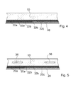
- Fig. 4 shows a sectional view of a household appliance cover plate according to the invention according to an alternative embodiment of the invention, in which the coating 24 comprises three metallic layers 22a, 22b, 22c.
- the various layers 22a to 22c are separated by dielectric separation layers 32a, 32b and the outer metallic layer 22c is surrounded by a protective layer 26.
- the dielectric separation layers 32a, 32b have a layer thickness that leads to deliberate and controlled interference between the portion of the light incident on the support plate 10, reflected by an upper layer 22a, on the one hand, and the portions of the light reflected by a lower layer 22b, 22c, on the other hand.
- a metallic iridescent, iridescent surface can be achieved.
- Examples of possible layer sequences are glass, iron and titanium nitride for producing a steel-like paint, glass, silicon dioxide, copper, silicon dioxide, iron (steel) and silica for a red shimmer, glass, silicon dioxide, a silicon-aluminum alloy (SiAl), Silica, iron (steel) and silica for a yellow color; and glass, silica, iron (steel), silica, iron (steel) and silica in different layer thicknesses for a bluish or grayish color.
- the protective layer 26 of titanium nitride is particularly robust.
- the protective layer 26 serves inter alia to avoid oxidation of the metallic layer 22 at high temperatures.
- electrical circuits can be engraved by means of a laser and the metallic layers 22a to 22c can be provided with contact elements not shown here to use the metallic layers 22a to 22c as conductors for transmitting control signals or the like can.
- the separating layers 32, 32a, 32b may be made of oxides of tin, zinc, titanium, aluminum, silicon, tantalum, niobium, nickel, chromium or mixtures thereof and / or of nitrides of titanium, silicon, aluminum, nickel, Chromium or mixtures thereof are produced.
- Fig. 5 shows a further alternative embodiment of the invention, in which the carrier plate 10 and the coating 24 are provided with laser internal engraving 36.
Landscapes
- Chemical & Material Sciences (AREA)
- Engineering & Computer Science (AREA)
- Materials Engineering (AREA)
- Life Sciences & Earth Sciences (AREA)
- Chemical Kinetics & Catalysis (AREA)
- General Chemical & Material Sciences (AREA)
- Geochemistry & Mineralogy (AREA)
- Organic Chemistry (AREA)
- Mechanical Engineering (AREA)
- General Engineering & Computer Science (AREA)
- Combustion & Propulsion (AREA)
- Physics & Mathematics (AREA)
- Electromagnetism (AREA)
- Laminated Bodies (AREA)
- Induction Heating Cooking Devices (AREA)
Abstract
Description
- Die Erfindung betrifft eine Hausgeräte-Abdeckplatte mit einer Trägerplatte aus Glas oder Glaskeramik mit wenigstens einem zumindest teilweise transparenten Bereich zum Abdecken eines Anzeigeelements sowie mit einer Beschichtung. Ein weiterer Aspekt der Erfindung betrifft ein Verfahren zum Herstellen einer solchen Hausgeräte-Abdeckplatte.
- Aus der
WO 2007/118744 A1 ist eine Hausgeräte-Abdeckplatte mit einer metallartigen Schicht bekannt. Die metallartige Schicht überdeckt auf die Rückseite der Abdeckplatte aufgedruckte Dekorabschnitte, um diese zu schützen. - Ferner ist aus der
DE 100 14 373 C2 ein Kochfeld mit einer Glaskeramikplatte bekannt, die eine metallartige Beschichtung aufweist. Solche metallartigen Beschichtungen sind ästhetisch sehr ansprechend, eröffnen neue Möglichkeiten für das Hausgerätedesign und erlauben insbesondere ein metallisches Aussehen von Glaskeramik-Abdeckplatten, wodurch diese in ihrem Gesamteindruck an Metallteile des Hausgeräts angepasst werden können. Beispielsweise kann im Falle eines Kochfelds eine Glaskeramikabdeckplatte in einem Edelstahl-Look ermöglicht werden, die sich besonders harmonisch in eine Küche mit Edelstahl-Bauteilen einfügt. - Aus der
US 2008/0264931 A1 ist eine Abdeckplatte für ein Kochfeld bekannt, die mit einer semitransparenten Metallschicht beschichtet ist. Die semitransparente Metallschicht kann zusätzlich zu einer Farbschicht zum Erzeugen eines metallischen Glanzes aufgebracht werden. - Der Erfindung liegt insbesondere die Aufgabe zugrunde, die Gestaltungsmöglichkeiten gattungsgemäßer Abdeckplatten zu erweitern. Eine weitere Aufgabe der Erfindung ist es, ein Verfahren zum Herstellen einer solchen Abdeckplatte bereitzustellen.
- Diese Aufgaben werden insbesondere durch eine Hausgeräte-Abdeckplatte nach dem Anspruch 1 und durch ein Verfahren nach dem Anspruch 14 gelöst. Weitere vorteilhafte Ausgestaltungen und Weiterbildungen der Erfindung ergeben sich aus den Unteransprüchen.
- Die Erfindung geht insbesondere aus von einer Hausgeräte-Abdeckplatte mit einer Trägerplatte aus Glas oder Glaskeramik mit wenigstens einem zumindest teilweise transparenten Bereich zum Abdecken eines Anzeigeelements sowie mit einer Beschichtung.
- Es wird vorgeschlagen, dass die Beschichtung zumindest eine semitransparente metallische Schicht mit einer Schichtdicke zwischen 10 nm und 50 nm und zumindest eine weitere metallische Schicht umfasst, die durch eine dielektrische Schicht von der semitransparenten metallischen Schicht getrennt ist. In dem genannten Bereich von Schichtdicken ist die Beschichtung einerseits hinreichend transparent um das Durchscheinen von leuchtenden Elementen, wie beispielsweise Anzeigeelementen wie Leuchtdioden oder 7 -Segment -Anzeigen, zu erlauben, und im Übrigen, insbesondere bei ausgeschaltetem Anzeigeelement, eine metallisch reflektierende Oberfläche zu erzeugen. Für Schichtdicken unterhalb von 10 nm ergibt sich eine zu starke Transparenz, die die Beschichtung nicht mehr metallisch erscheinen lässt, während bei Schichtdicken oberhalb von 50 nm die Transparenz nicht mehr ausreichend ist, um das Durchscheinen von Anzeigeelementen und/oder rötlich leuchtenden Heizelementen zu ermöglichen. Besonders vorteilhaft ist eine Transmission von 30 % - 80 % für rotes Licht mit einer Wellenlänge von 700 - 800 nm. Durch das Vorsehen einer weiteren metallischen Schicht kann von der semitransparenten Schicht durchgelassenes Licht reflektiert werden und in der dielektrischen Schicht mit dem durchgelassenen Licht interferieren. Dadurch wird eine besonders eindrucksvolle, schillernde Oberfläche erzeugt, die neue Möglichkeiten für das Design eröffnet. Die Dicke der dielektrischen Schicht kann insbesondere weniger als 800 nm betragen. Dadurch liegt die Schichtdicke im Bereich von sichtbarem Licht, was zu interessanten Interferenzeffekten zwischen den Lichtanteilen führt, die von den unterschiedlichen metallischen Schichten reflektiert werden. Die Interferenzeffekte können zum Erzeugen einer irisierend schimmernden Oberfläche genutzt werden und/oder so gewählt werden, dass bestimmte Farbanteile absorbiert werden und dass das reflektierte Licht eine bestimmte Farbe annimmt. Dazu können insbesondere auch Abstände von weniger als 500 nm gewählt werden.
- Die erfindungsgemäße Hausgeräte-Abdeckplatte ist in vielen unterschiedlichen Bereichen einsetzbar. Beispielsweise kann die Abdeckplatte als Kochfeld-Abdeckplatte eines Kochfelds, insbesondere eines Induktionskochfelds oder Strahlungskochfelds, oder als Frontplatte einer Hausgerätetür, beispielsweise eines Backofens, Mikrowellenherds oder Dampfgarers, eingesetzt werden. Ferner ist ein Einsatz in Kühlschränken, Spülmaschinen, Waschmaschinen und Wäschetrocknern denkbar. Die Vorteile der Erfindung kommen insbesondere dann zum Tragen, wenn hinter der Abdeckplatte neben Anzeigeelementen auch Berührungssensoren angeordnet sind, die eine Benutzerschnittstelle eines Hausgeräts bilden. Der metallische Look kann dann derart perfektioniert werden, dass die Benutzerschnittstelle im inaktiven Zustand des Hausgeräts beinahe vollständig hinter der spiegelnden Metallschicht verschwindet. Im aktiven Zustand des Hausgeräts können Leuchtelemente der Benutzerschnittstelle aktiviert werden, die dann durch die teilweise transparente metallische Schicht hindurch scheinen.
- Eine Beschädigung oder Korrosion der metallischen Schicht kann vermieden werden, wenn diese auf eine dem Anzeigeelement zugewandte Rückseite der Trägerplatte aufgebracht ist und/oder wenn diese von einer dielektrischen Schutzschicht bedeckt ist.
- Besonders interessante Effekte können erreicht werden, wenn die Abdeckplatte wenigstens zwei zumindest teilweise transparente metallische Schichten umfasst, deren Schichtdicke insbesondere in dem oben genannten Bereich von 10 nm bis 50 nm liegen kann. Diese können durch eine dielektrische Schicht voneinander getrennt sein, deren Dicke insbesondere zwischen 5 nm und 500 nm, vorzugsweise zwischen 10 nm und 100 nm, liegen kann.
- Eine kapazitive Berührungssensorik ist ermöglicht, und wenigstens eine der metallischen Schichten weist in der Umgebung eines Bereichs zur Abdeckung eines Berührungssensors zur elektrischen Isolation des Bereichs eine Unterbrechung auf. Der Berührungssensor wird dann nicht durch die gesamte, als großflächige Elektrode wirkende Beschichtung abgeschirmt, sondern nur durch einen kleinen, durch die insbesondere linienförmige Unterbrechung definierten und isolierten Bereich der Beschichtung, die in einer Umgebung des Berührungssensors auch vollständig fehlen kann. Durch die Unterbrechung kann auch eine Abschirmung von induktiven Sensoren durch die Beschichtung vermieden werden.
- Eine Störung des metallischen Gesamteindrucks durch großflächige, schwarz erscheinende Fenster kann vermieden werden, wenn die metallische Schicht entlang von Linien mit einer Breite von weniger als 2 mm, insbesondere von weniger als 0,2 mm, unterbrochen ist. Die Unterbrechung kann insbesondere durch Einritzen der metallischen Schicht hergestellt sein. Dazu kann das metallische Material beispielsweise zur Herstellung der Unterbrechung von einem Laser abgetragen werden. So sind auch Unterbrechungen mit einer Breite von weniger als 1 mm einfach und kostengünstig realisierbar.
- Weitere Gestaltungsmöglichkeiten können eröffnet werden, wenn die Hausgeräte-Abdeckplatte eine zumindest in Teilbereichen auf die Trägerplatte aufgedruckte Markierungsschicht umfasst. Die Markierungsschicht kann insbesondere in einem Siebdruckverfahren oder in einem Tintenstrahl-Druckverfahren auf die Rückseite der Trägerplatte aufgedruckt sein. In einer besonders vorteilhaften Ausgestaltung der Erfindung werden eine oder beide metallischen Schichten nach dem Aufdrucken der Markierungsschicht auf die Trägerplatte aufgebracht.
- Die metallische Schicht kann als Leiterbahn und/oder Kontrollelektrode verwendet werden, wenn die Hausgeräte-Abdeckplatte wenigstens eine mit der metallischen Schicht verbundene Kontaktelektrode zum Einspeisen von Steuersignalen in die metallische Schicht umfasst.
- Metallische Schichten mit einer präzise definierten Schichtdicke können beispielsweise durch eine physikalische Gasphasenabscheidung (englisch: Physical Vapor Deposition, kurz: PVD) hergestellt werden. Das Verfahren ist insbesondere durch eine Gaserzeugung der schichtbildenden Teilchen, den Transport des Dampfes zum Substrat und die Kondensation des Dampfes auf dem Substrat zur Schichtbildung gekennzeichnet. Als Metallmaterialien für die metallische Schicht kann Eisen, Stahl, Kupfer oder eine geeignete Legierung wie Silicium mit Aluminium gewählt werden. Zwischen der Trägerplatte und der Metallschicht kann eine Schicht aus Siliciumdioxid vorgesehen sein, die auch durch eine natürliche Oxidation der Oberfläche der Trägerplatte entstehen kann.
- Die Gestaltungsfreiheit kann weiter verbessert werden, wenn die Trägerplatte und/oder die Beschichtung einer Laser-Innengravur umfasst.
- Ein weiterer Korrosionsschutz kann erreicht werden, wenn zumindest eine äußere Schicht der metallischen Schichten von einer dielektrischen Schutzschicht bedeckt ist.
- In denkbaren Ausgestaltungen ist zumindest eine der metallischen Schichten aus einem Material hergestellt, welches aus der Gruppe, die aus Silber (Ag), Gold (Au), Aluminium (AI), Molybdän (Mo), Kupfer (Cu), Nickel (Ni), Silizium (Si), Edelstahl (SSt), Titan (Ti), Niob (Nb), Tantal (Ta), Wolfram (W), Palladium oder einer Legierung oder Mischung aus zwei oder mehreren dieser Metalle besteht, ausgewählt ist.
- Eine schwarz schimmernde Schicht kann erreicht werden, wenn eine Ni-Cr Legierung mit 80 % Nickel und 20 % Chrom verwendet wird.
- Als Material wenigstens einer der dielektrischen Trennschichten haben sich Oxide, welche aus der Gruppe, die aus Zinnoxiden, Zinkoxiden, Aluminiumoxiden, Titanoxiden, Siliziumoxiden, Nickeloxiden, Chromoxiden, Nioboxiden, Tantaloxiden oder Mischungen davon besteht, ausgewählt sind, und/oder Nitride aus metallischen Elementen, welche aus der Gruppe, die aus Siliziumnitriden, Titannitdriden, Chromnitriden und Aluminiumnitriden oder Mischungen davon besteht, ausgewählt sind, als vorteilhaft erwiesen.
- Ein weiterer Aspekt der Erfindung betrifft ein Verfahren zum Herstellen einer Abdeckplatte der oben beschriebenen Art.
- Weitere Vorteile und Merkmale der Erfindung ergeben sich aus der folgenden Zeichnungsbeschreibung. In der Zeichnung sind Ausführungsbeispiele der Erfindung dargestellt. Die Zeichnung, die Beschreibung und die Ansprüche enthalten zahlreiche Merkmale in Kombination. Der Fachmann wird diese Merkmale zweckmäßigerweise auch einzeln betrachten und zu sinnvollen weiteren Kombinationen zusammenfassen.
- Es zeigen:
- Fig. 1
- ein Kochfeld mit einer Abdeckplatte, einem Anzeigeelement und mehreren Bedienelementen in einer Draufsicht,
- Fig. 2
- eine schematische Schnittdarstellung der Abdeckplatte nach
Fig. 1 , - Fig. 3
- eine Hausgeräte-Abdeckplatte nach einer weiteren Ausgestaltung der Erfindung mit zwei metallischen Schichten,
- Fig. 4
- eine Hausgeräte-Abdeckplatte nach einer weiteren Ausgestaltung der Erfindung mit drei metallischen Schichten, und
- Fig. 5
- eine Schnittdarstellung einer Hausgeräte-Abdeckplatte nach einer weiteren Ausgestaltung der Erfindung mit Laser-Innengravuren.
-
Fig. 1 zeigt ein Kochfeld mit einer Abdeckplatte, die eine gedruckte Trägerplatte 10 aus Glas oder Glaskeramik umfasst. Auf die der Sichtseite der Trägerplatte 10 abgewandte Rückseite der Trägerplatte 10 sind verschiedene Markierungen 12 aufgedruckt, die durch das Glaskeramikmaterial der Trägerplatte 10 hindurch sichtbar sind. - Die Markierungen 12 sind in einem Siebdruckverfahren aufgebracht und markieren in einer an sich bekannten Weise Heizzonen 14a bis 14d des Kochfelds sowie die Elemente einer Benutzerschnittstelle 16.
- Die Benutzerschnittstelle 16 umfasst ein hier vereinfacht als 7-Segment-Anzeige dargestelltes Anzeigeelement 18 mit mehreren Leuchtdioden 20 (
Fig. 2 ). Nach dem Aufdrucken der Markierungen 12 wurde in einem Herstellungsverfahren zum Herstellen der erfindungsgemäßen Hausgeräte-Abdeckplatte eine Beschichtung 24 auf die Rückseite der Trägerplatte 10 aufgebracht, die mehrere metallische Schichten 22a - 22c (Fig. 3 ) umfasst, deren Schichtdicke zwischen 10 nm und 50 nm liegt. In dem inFig. 1 dargestellten Ausführungsbeispiel umfasst die Beschichtung 24 (Fig. 2 ) eine Edelstahlschicht und eine Kupferschicht, die durch physikalische Gasphasenabscheidung erzeugt wurden. -
Fig. 2 zeigt eine Schnittdarstellung der Abdeckplatte ausFig. 1 . Die Schnittdarstellung ist stark schematisiert. Insbesondere die Größenverhältnisse sind stark verzerrt. Die Trägerplatte 10 ist an ihrer Rückseite mit einer serigraphisch hergestellten Markierung 12 bedruckt und anschließend mit einer Beschichtung 24 beschichtet, die in einem Sputter- oder PVD-Verfahren hergestellt wurde. -
Figur 3 zeigt eine Schnittdarstellung des Schichtaufbaus der Beschichtung 24. Auf eine hier nicht dargestellte Siliciumdioxid-Schicht auf der Rückseite des Substrats der Trägerplatte 10 ist zunächst eine erste metallische Schicht 22a aus Eisen/Edelstahl, dann eine dielektrische Trennschicht 32 mit einer Dicke D zwischen 10 und 100 nm und anschließend eine zweite metallische Schicht 22b aus Kupfer aufgebracht, die durch eine dielektrische Schutzschicht 26 vor Beschädigungen geschützt ist. Die Dicke der metallischen Schichten 22a, 22b liegt zwischen 10 nm und 50 nm, vorzugsweise zwischen 20 nm und 40 nm, während die Dicke der Schutzschicht 26 mehrere 100 nm beträgt. - Hinter der Abdeckplatte bzw. der Trägerplatte 10 ist eine Leuchtdiode 20 (
Fig. 2 ) des Anzeigeelements 18 angeordnet, deren Licht durch die metallischen Schichten 22a, 22b, die Trennschicht 32, die Schutzschicht 26 und die Trägerplatte 10 hindurch von der Sichtseite der Trägerplatte 10 aus wahrnehmbar ist. - Da die metallischen Schichten 22a, 22b nach der Markierung 12 auf die Trägerplatte 10 aufgebracht sind, überdecken die metallischen Schichten 22a, 22b von der Rückseite der Trägerplatte 10 aus betrachtet auch die Markierung 12. Eine der metallischen Schichten 22a, 22b und/oder die Trennschicht 23 können alternativ Aussparungen aufweisen, die beispielsweise mit einer Maske aufgebracht werden können. Dadurch können diese Schichten die Funktion der Markierung 12 übernehmen, die dann entfallen kann.
- Die metallischen Schichten 22a, 22b ist entlang einer linienförmigen Unterbrechung 30 durch eine Laserbearbeitung entfernt worden. Der unmittelbar oberhalb des Berührungssensors 28 und in dessen unmittelbarer Umgebung liegende Bereich 38 der Beschichtung 24 ist daher elektrisch von den anderen Teilen isoliert und nicht elektrisch leitend mit anderen Teilen der metallischen Beschichtung 24 verbunden. Eine Breite des Spalts, der die Unterbrechung 30 bildet, liegt im Bereich von weniger als 0,2 mm, so dass die Unterbrechung 30 von der Sichtseite der Trägerplatte 10 aus allenfalls als sehr dünne Linie sichtbar ist, während die Abdeckplatte im Übrigen im Bereich des Berührungssensors 28 eine durchgängige, metallisch erscheinende Oberfläche hat.
- Die metallischen Schichten 22a, 22b sind semitransparent, so dass die gesamte Fläche der Abdeckplatte einen teilweise transparenten Bereich 40 bildet.
- Durch die geringe Dicke der metallischen Schichten 22a, 22b ist einerseits eine hinreichende Transparenz gewährleistet, so dass das Licht der Leuchtdiode 20 durch die Beschichtung 24 hindurch scheinen kann. Andererseits reflektieren die metallische Schicht 22a, 22b das durch die Trägerplatte 10 einfallende Licht derart, dass bei inaktiver Leuchtdiode 20 nur die durchgehende Schicht 22 erkennbar ist. Die Abdeckplatte wirkt demnach wie ein semitransparenter Spiegel.
- Die Anteile des Lichts, die von der hinteren metallischen Schicht 22b reflektiert werden, interferieren mit den Anteilen des Lichts, die von der vorderen metallischen Schicht 22a reflektiert werden. Diese Interferenzen führen zu einer interessant schillernden Oberfläche.
-
Fig. 4 zeigt eine Schnittdarstellung einer erfindungsgemäßen Hausgeräte-Abdeckplatte nach einer alternativen Ausgestaltung der Erfindung, in welche die Beschichtung 24 drei metallische Schichten 22a, 22b, 22c umfasst. Die verschiedenen Schichten 22a bis 22c sind durch dielektrische Trennschichten 32a, 32b voneinander getrennt und die äußere metallische Schicht 22c ist von einer Schutzschicht 26 umgeben. Die dielektrischen Trennschichten 32a, 32b haben eine Schichtdicke, die zu gewollten und kontrollierten Interferenzen zwischen den von einer oberen Schicht 22a reflektierten Anteil des durch die Trägerplatte 10 einfallenden Lichts einerseits und den von einer unteren Schicht 22b, 22c reflektierten Anteilen des Lichts andererseits führt. Dadurch kann eine metallisch schillernde, irisierende Oberfläche erreicht werden. - Beispiele für mögliche Schichtfolgen sind Glas, Eisen bzw. Stahl und Titannitrid zum Herstellen einer stahlartigen Farbe, Glas, Siliciumdioxid, Kupfer, Siliciumdioxid, Eisen (Stahl) und Siliciumdioxid für einen roten Schimmer, Glas, Siliciumdioxid, eine Silicium-Aluminiumlegierung (SiAl), Siliciumdioxid, Eisen (Stahl) und Siliciumdioxid für eine gelbe Farbe sowie Glas, Siliciumdioxid, Eisen (Stahl), Siliciumdioxid, Eisen (Stahl) und Siliciumdioxid in unterschiedlichen Schichtdicken für eine bläuliche oder gräuliche Farbgebung.
- Die Schutzschicht 26 aus Titannitrid ist besonders robust. Die Schutzschicht 26 dient unter anderem der Vermeidung einer Oxidation der metallischen Schicht 22 bei hohen Temperaturen.
- In die unterschiedlichen metallischen Schichten 22a bis 22c können mit Hilfe eines Lasers elektrische Schaltkreise eingraviert werden und die metallischen Schichten 22a bis 22c können mit hier nicht dargestellten Kontaktelementen versehen werden, um die metallischen Schichten 22a bis 22c als Leiter zum Übertragen von Steuersignalen oder dergleichen verwenden zu können.
- In den oben beschriebenen Ausführungsbeispielen können die Trennschichten 32, 32a, 32b aus Oxiden von Zinn, Zink, Titan, Aluminium, Silizium, Tantal, Niob, Nickel, Chrom oder Mischungen daraus und/oder aus Nitriden von Titan, Silizium, Aluminium, Nickel, Chrom oder Mischungen daraus hergestellt werden.
-
Fig. 5 zeigt ein weiteres alternatives Ausführungsbeispiel der Erfindung, in welchem die Trägerplatte 10 und die Beschichtung 24 mit Laser-Innengravuren 36 ausgestattet sind. -
- 10
- Trägerplatte
- 12
- Markierungen
- 14a
- Heizzone
- 14b
- Heizzone
- 14c
- Heizzone
- 14d
- Heizzone
- 16
- Benutzerschnittstelle
- 18
- Anzeigeelement
- 20
- Leuchtdiode
- 22a
- Schicht
- 22b
- Schicht
- 22c
- Schicht
- 24
- Beschichtung
- 26
- Schutzschicht
- 28
- Berührungssensor
- 30
- Unterbrechung
- 32
- Trennschicht
- 32a
- Trennschicht
- 32b
- Trennschicht
- 36
- Laser-Innengravur
- 38
- Bereich
- 40
- Bereich
- D
- Dicke
Claims (14)
- Haushaltsgeräte-Abdeckplatte mit einer Trägerplatte (10) aus Glas oder Glaskeramik mit wenigstens einem zumindest teilweise transparenten Bereich (40) zum Abdecken eines Anzeigeelements (18) sowie mit einer Beschichtung (24), wobei die Beschichtung (24) zumindest eine semitransparente metallische Schicht (22a) mit einer Schichtdicke zwischen 10 nm und 50 nm und zumindest eine weitere metallische Schicht (22a - 22c) umfasst, die durch eine dielektrische Trennschicht (32, 32a, 32b) von der semitransparenten metallischen Schicht (22a) getrennt ist, dadurch gekennzeichnet, dass wenigstens eine der metallischen Schichten (22a - 22c) in der Umgebung eines Bereichs (38) zur Abdeckung eines Berührungssensors eine Unterbrechung (30) zur elektrischen Isolation des Bereichs (38) aufweist, und der Berührungssensor (28) zur Ausbildung einer kapazitiven Berührungssensorik mit dem Bereich (38) elektrisch kontaktiert ist.
- Haushaltsgeräte-Abdeckplatte nach Anspruch 1, dadurch gekennzeichnet, dass die semitransparente metallische Schicht (22) auf eine dem Anzeigeelement (18) zugewandte Rückseite der Trägerplatte (10) aufgebracht ist.
- Hausgeräte-Abdeckplatte nach einem der vorhergehenden Ansprüche, gekennzeichnet durch wenigstens zwei zumindest teilweise transparente metallische Schichten (22a - 22c), die durch eine dielektrische Trennschicht (32, 32a, 32b) getrennt sind.
- Hausgeräte-Abdeckplatte nach Anspruch 3, dadurch gekennzeichnet, dass die Dicke (D) der dielektrischen Schicht zwischen den wenigstens zwei metallischen Schichten (22a - 22c) zwischen 5 nm und 500 nm liegt.
- Hausgeräte-Abdeckplatte nach einem der vorhergehenden Ansprüche, dadurch gekennzeichnet, dass die Unterbrechung (30) durch Einritzen der metallischen Schicht (22) hergestellt ist.
- Hausgeräte-Abdeckplatte nach einem der vorhergehenden Ansprüche, gekennzeichnet durch eine zumindest in Teilbereichen auf die Trägerplatte (10) aufgedruckte Markierung (12).
- Hausgeräte-Abdeckplatte nach Anspruch 6, dadurch gekennzeichnet, dass zumindest eine der metallischen Schichten (22a - 22c) nach dem Aufdrucken der Markierung (12) auf die Trägerplatte (10) aufgebracht ist.
- Hausgeräte-Abdeckplatte nach einem der vorhergehenden Ansprüche, gekennzeichnet durch wenigstens eine mit zumindest einer der metallischen Schichten (22a - 22c) verbundene Kontaktelektrode zum Einspeisen von Steuersignalen in die metallische Schicht (22).
- Hausgeräte-Abdeckplatte nach einem der vorhergehenden Ansprüche, dadurch gekennzeichnet, dass zumindest eine der metallischen Schichten (22a - 22c) in einem PVD-Sputterverfahren auf die Trägerplatte (10) aufgebracht ist.
- Hausgeräte-Abdeckplatte nach einem der vorhergehenden Ansprüche, dadurch gekennzeichnet, dass eine äußere metallische Schicht (22c) von einer dielektrischen Schutzschicht (26) bedeckt ist.
- Hausgeräte-Abdeckplatte nach einem der vorhergehenden Ansprüche, dadurch gekennzeichnet, dass zumindest eine der metallischen Schichten (22a - 22c) aus einem Material hergestellt ist, welches aus der Gruppe, die aus Silber (Ag), Gold (Au), Aluminium (Al), Molybdän(Mo), Kupfer (Cu), Nickel (Ni), Silizium (Si), Edelstahl (SSt), Titan (Ti), Niob (Nb), Tantal (Ta), Wolfram (W), Palladium oder einer Legierung oder Mischung aus zwei oder mehreren dieser Metalle besteht, ausgewählt ist.
- Hausgeräte-Abdeckplatte nach einem der vorhergehenden Ansprüche, dadurch gekennzeichnet, dass das Material wenigstens eine der dielektrischen Trennschichten (32, 32a, 32b)- Oxide, welche aus der Gruppe, die aus Zinnoxiden, Zinkoxiden, Aluminiumoxiden, Titanoxiden, Siliziumoxiden, Nickeloxiden, Chromoxiden, Nioboxiden, Tantaloxiden oder Mischungen davon besteht, ausgewählt sind, und/oder- Nitride aus metallischen Elementen, welche aus der Gruppe, die aus Siliziumnitriden, Titannitdriden, Chromnitriden und Aluminiumnitriden oder Mischungen davon besteht, ausgewählt sind,
umfasst. - Hausgeräte-Abdeckplatte nach einem der vorhergehenden Ansprüche, dadurch gekennzeichnet, dass die Trägerplatte (10) wenigstens eine Markierung in der Form einer Laser-Innengravur (36) umfasst.
- Verfahren zum Herstellen einer Haushaltsgeräte-Abdeckplatte mit einer Trägerplatte (10) aus Glas oder Glaskeramik mit wenigstens einem zumindest teilweise transparenten Bereich (40) zum Abdecken eines Anzeigeelements (18) sowie mit einer Beschichtung (24), wobei die Beschichtung (24) mit zumindest einer semitransparenten metallischen Schicht (22a) mit einer Schichtdicke zwischen 10 nm und 50 nm und zumindest mit einer weiteren metallischen Schicht (22a - 22c) ausgebildet wird, die durch eine dielektrische Trennschicht (32, 32a, 32b) von der semitransparenten metallischen Schicht (22a) getrennt wird, dadurch gekennzeichnet, dass wenigstens eine der metallischen Schichten (22a - 22c) in der Umgebung eines Bereichs (38) zur Abdeckung eines Berührungssensors (28) mit einer Unterbrechung (30) zur elektrischen Isolation des Bereichs (38) ausgebildet wird, und der Berührungssensor (28) zur Ausbildung einer kapazitiven Berührungssensorik mit dem Bereich (38) elektrisch kontaktiert wird.
Priority Applications (1)
| Application Number | Priority Date | Filing Date | Title |
|---|---|---|---|
| EP12190740.6A EP2559672B1 (de) | 2009-08-17 | 2010-08-06 | Hausgeräte-Abdeckplatte mit Fabry-Perot Interferenzschicht |
Applications Claiming Priority (4)
| Application Number | Priority Date | Filing Date | Title |
|---|---|---|---|
| EP09382146 | 2009-08-17 | ||
| ES200930605A ES2394378A1 (es) | 2009-08-17 | 2009-08-18 | Placa de cubierta de aparato doméstico. |
| EP12190740.6A EP2559672B1 (de) | 2009-08-17 | 2010-08-06 | Hausgeräte-Abdeckplatte mit Fabry-Perot Interferenzschicht |
| EP10739373.8A EP2467344B1 (de) | 2009-08-17 | 2010-08-06 | Hausgeräte-abdeckplatte mit fabry-pérot interferenzschicht |
Related Parent Applications (3)
| Application Number | Title | Priority Date | Filing Date |
|---|---|---|---|
| EP10739373.8A Division-Into EP2467344B1 (de) | 2009-08-17 | 2010-08-06 | Hausgeräte-abdeckplatte mit fabry-pérot interferenzschicht |
| EP10739373.8A Division EP2467344B1 (de) | 2009-08-17 | 2010-08-06 | Hausgeräte-abdeckplatte mit fabry-pérot interferenzschicht |
| EP10739373.8 Division | 2010-08-06 |
Publications (2)
| Publication Number | Publication Date |
|---|---|
| EP2559672A1 true EP2559672A1 (de) | 2013-02-20 |
| EP2559672B1 EP2559672B1 (de) | 2015-06-10 |
Family
ID=42827344
Family Applications (2)
| Application Number | Title | Priority Date | Filing Date |
|---|---|---|---|
| EP12190740.6A Active EP2559672B1 (de) | 2009-08-17 | 2010-08-06 | Hausgeräte-Abdeckplatte mit Fabry-Perot Interferenzschicht |
| EP10739373.8A Active EP2467344B1 (de) | 2009-08-17 | 2010-08-06 | Hausgeräte-abdeckplatte mit fabry-pérot interferenzschicht |
Family Applications After (1)
| Application Number | Title | Priority Date | Filing Date |
|---|---|---|---|
| EP10739373.8A Active EP2467344B1 (de) | 2009-08-17 | 2010-08-06 | Hausgeräte-abdeckplatte mit fabry-pérot interferenzschicht |
Country Status (4)
| Country | Link |
|---|---|
| US (1) | US20120125314A1 (de) |
| EP (2) | EP2559672B1 (de) |
| CN (1) | CN102574737A (de) |
| WO (1) | WO2011020718A1 (de) |
Cited By (2)
| Publication number | Priority date | Publication date | Assignee | Title |
|---|---|---|---|---|
| EP2801556A1 (de) * | 2013-05-07 | 2014-11-12 | Schott AG | Beschichtete Glaskeramikplatte |
| DE102024111841A1 (de) * | 2024-04-26 | 2025-10-30 | Schott Ag | Glaskeramischer Artikel |
Families Citing this family (23)
| Publication number | Priority date | Publication date | Assignee | Title |
|---|---|---|---|---|
| US8837120B2 (en) * | 2010-12-17 | 2014-09-16 | Bsh Home Appliances Corporation | Transparent display for home appliances |
| USD708003S1 (en) * | 2010-12-27 | 2014-07-01 | Western Industries, Inc. | Cook top |
| ES2392713B1 (es) * | 2011-03-30 | 2013-11-08 | Bsh Electrodomésticos España, S.A. | Placa de campo de cocción, y campo de cocción con una placa de campo de cocción correspondiente |
| ES2401890B1 (es) * | 2011-06-29 | 2014-04-10 | BSH Electrodomésticos España S.A. | Dispositivo de aparato doméstico |
| WO2013024092A1 (de) * | 2011-08-17 | 2013-02-21 | BSH Bosch und Siemens Hausgeräte GmbH | Hausgerätevorrichtung mit einem überspannungsschutz |
| ES2452939B1 (es) * | 2012-10-03 | 2015-03-12 | Bsh Electrodomesticos Espana | Dispositivo de aparato doméstico |
| WO2014060918A1 (de) * | 2012-10-19 | 2014-04-24 | BSH Bosch und Siemens Hausgeräte GmbH | Verfahren zur herstellung einer kochfeldplatte, vorrichtung dafür und kochfeldplatte |
| DE102012221499A1 (de) * | 2012-11-23 | 2014-05-28 | BSH Bosch und Siemens Hausgeräte GmbH | Haushaltskältegerät mit einem Anzeigemittel für einen Behälterdeckel |
| FR2999563B1 (fr) * | 2012-12-19 | 2015-02-27 | Eurokera | Feuille de vitroceramique munie d'un revetement de couches minces |
| EP2757079B1 (de) * | 2013-01-21 | 2020-04-22 | BSH Hausgeräte GmbH | Kochfeldvorrichtung |
| ES2501340B1 (es) * | 2013-04-01 | 2015-07-08 | Bsh Electrodomésticos España, S.A. | Dispositivo de aparato doméstico |
| ES2504765B1 (es) * | 2013-04-04 | 2015-08-12 | Bsh Electrodomésticos España, S.A. | Procedimiento para una fabricación de al menos un dispositivo de aparato doméstico, y dispositivo de aparato doméstico |
| ES2547265B1 (es) * | 2014-04-02 | 2016-07-13 | Bsh Electrodomésticos España, S.A. | Procedimiento para fabricar un componente de aparato doméstico con un grabado en un cuerpo base provisto de un recubrimiento, y componente de aparato doméstico |
| WO2016012325A1 (fr) * | 2014-07-25 | 2016-01-28 | Agc Glass Europe | Panneau de verre décoratif |
| EP2977202A1 (de) * | 2014-07-25 | 2016-01-27 | AGC Glass Europe | Beheizbare Verglasung |
| JP6398589B2 (ja) * | 2014-10-17 | 2018-10-03 | 日本電気硝子株式会社 | 調理器用トッププレート |
| EP3031785B1 (de) * | 2014-12-12 | 2018-10-17 | Schott AG | Verfahren zur herstellung eines glaskeramikelements mit strukturierter beschichtung |
| US10288476B2 (en) | 2015-12-21 | 2019-05-14 | Apple Inc. | Ambient light sensor window coatings for electronic devices |
| FR3069735B1 (fr) | 2017-07-31 | 2023-01-20 | Leroy Somer Moteurs | Rotor a cage injectee |
| FR3069734B1 (fr) | 2017-07-31 | 2022-12-30 | Leroy Somer Moteurs | Rotor a cage injectee |
| KR102933616B1 (ko) * | 2019-12-18 | 2026-03-05 | 엘지전자 주식회사 | 박막의 열 변형을 줄인 유도 가열 방식의 쿡탑 |
| KR20210105777A (ko) * | 2020-02-19 | 2021-08-27 | 엘지전자 주식회사 | 사용 편의성이 개선된 유도 가열 방식의 쿡탑 |
| CN116535248B (zh) * | 2023-05-23 | 2024-07-19 | 广东天弼陶瓷有限公司 | 一种具有金属光泽且立体感强的抛釉洞石砖及其制备方法 |
Citations (7)
| Publication number | Priority date | Publication date | Assignee | Title |
|---|---|---|---|---|
| WO2000073984A1 (en) * | 1999-06-02 | 2000-12-07 | Elo Touchsystems Incorporated | Projective capacitive touchscreen |
| DE10014373C2 (de) | 2000-03-23 | 2003-12-11 | Schott Glas | Kochfeld |
| WO2007025872A2 (de) * | 2005-08-30 | 2007-03-08 | BSH Bosch und Siemens Hausgeräte GmbH | Kapazitiver stellstreifen und haushaltsgerät mit einem solchen |
| WO2007118744A1 (de) | 2006-04-12 | 2007-10-25 | BSH Bosch und Siemens Hausgeräte GmbH | Platteneinheit mit beständigem dekor |
| US20070295711A1 (en) * | 2006-06-16 | 2007-12-27 | Harald Striegler | Cook top comprising a glass ceramic plate having an opaque coating and an improved window coating on a display window on an underside of the plate |
| US20080190409A1 (en) * | 2005-05-20 | 2008-08-14 | Eurokera S.N.C. | Glass-Ceramic Plate and Method for the Production Thereof |
| US20080264931A1 (en) | 2005-12-05 | 2008-10-30 | Pablo Vilato | Transparent or Translucent Glass Ceramic Plate and a Method for the Production Thereof |
Family Cites Families (7)
| Publication number | Priority date | Publication date | Assignee | Title |
|---|---|---|---|---|
| US3649359A (en) * | 1969-10-27 | 1972-03-14 | Optical Coating Laboratory Inc | Multilayer filter with metal dielectric period |
| US4290061A (en) * | 1979-08-23 | 1981-09-15 | General Electric Company | Electrically integrated touch input and output display system |
| DE4126626C2 (de) * | 1990-08-15 | 1994-08-04 | United Distillers Plc | Markierter Materialkörper und Verfahren zu dessen Herstellung |
| DE50308334D1 (de) * | 2002-05-07 | 2007-11-22 | Schott Ag | Beleuchtungseinrichtung für Schaltflächen |
| WO2003098115A1 (fr) * | 2002-05-16 | 2003-11-27 | Nippon Electric Glass Co., Ltd. | Plaque de cuisson superieure |
| FR2885071B1 (fr) * | 2005-04-28 | 2010-02-12 | Becton Dickinson France | Procede d'identification d'un contenant et/ou d'un article fini obtenu a partir dudit contenant, en particulier a usage medical |
| EP2226567A4 (de) * | 2007-12-20 | 2016-03-09 | Nippon Electric Glass Co | Oberplatte für einen kochherd und herstellungsverfahren dafür |
-
2010
- 2010-08-06 EP EP12190740.6A patent/EP2559672B1/de active Active
- 2010-08-06 EP EP10739373.8A patent/EP2467344B1/de active Active
- 2010-08-06 CN CN2010800363679A patent/CN102574737A/zh active Pending
- 2010-08-06 US US13/388,466 patent/US20120125314A1/en not_active Abandoned
- 2010-08-06 WO PCT/EP2010/061502 patent/WO2011020718A1/de not_active Ceased
Patent Citations (7)
| Publication number | Priority date | Publication date | Assignee | Title |
|---|---|---|---|---|
| WO2000073984A1 (en) * | 1999-06-02 | 2000-12-07 | Elo Touchsystems Incorporated | Projective capacitive touchscreen |
| DE10014373C2 (de) | 2000-03-23 | 2003-12-11 | Schott Glas | Kochfeld |
| US20080190409A1 (en) * | 2005-05-20 | 2008-08-14 | Eurokera S.N.C. | Glass-Ceramic Plate and Method for the Production Thereof |
| WO2007025872A2 (de) * | 2005-08-30 | 2007-03-08 | BSH Bosch und Siemens Hausgeräte GmbH | Kapazitiver stellstreifen und haushaltsgerät mit einem solchen |
| US20080264931A1 (en) | 2005-12-05 | 2008-10-30 | Pablo Vilato | Transparent or Translucent Glass Ceramic Plate and a Method for the Production Thereof |
| WO2007118744A1 (de) | 2006-04-12 | 2007-10-25 | BSH Bosch und Siemens Hausgeräte GmbH | Platteneinheit mit beständigem dekor |
| US20070295711A1 (en) * | 2006-06-16 | 2007-12-27 | Harald Striegler | Cook top comprising a glass ceramic plate having an opaque coating and an improved window coating on a display window on an underside of the plate |
Cited By (3)
| Publication number | Priority date | Publication date | Assignee | Title |
|---|---|---|---|---|
| EP2801556A1 (de) * | 2013-05-07 | 2014-11-12 | Schott AG | Beschichtete Glaskeramikplatte |
| US9884783B2 (en) | 2013-05-07 | 2018-02-06 | Schott Ag | Coated glass ceramic plate |
| DE102024111841A1 (de) * | 2024-04-26 | 2025-10-30 | Schott Ag | Glaskeramischer Artikel |
Also Published As
| Publication number | Publication date |
|---|---|
| EP2467344B1 (de) | 2014-10-08 |
| EP2559672B1 (de) | 2015-06-10 |
| EP2467344A1 (de) | 2012-06-27 |
| CN102574737A (zh) | 2012-07-11 |
| US20120125314A1 (en) | 2012-05-24 |
| WO2011020718A1 (de) | 2011-02-24 |
Similar Documents
| Publication | Publication Date | Title |
|---|---|---|
| EP2559672B1 (de) | Hausgeräte-Abdeckplatte mit Fabry-Perot Interferenzschicht | |
| EP2467345A1 (de) | Hausgeräte-abdeckplatte mit einer zumindest semitransparenten trägerplatte, hausgerät zum zubereiten von lebensmitteln und verfahren zum herstellen einer hausgeräte-abdeckplatte | |
| EP3135076B1 (de) | Scheibe mit beleuchteter schaltfläche und heizfunktion | |
| EP2013033B1 (de) | Kochfeldplatteneinheit mit eingebettetem dekor | |
| US10047004B2 (en) | Method of forming durable glass enamel | |
| EP2069550B1 (de) | Anzeige- und/oder bedienelement in einem kraftfahrzeug | |
| EP2074238B1 (de) | Kappe für ein anzeige- oder bedienelement mit lichtdurchlässiger metallbeschichtung und verfahren zu deren herstellung | |
| TW327657B (en) | Wafer made from transparent material and method for its production a repeated low-e-layer is coated on a wafer which is made from transparent material or on a foil with high transmission characteristics in a visible region. | |
| WO2011020721A1 (de) | Verfahren zum herstellen einer hausgeräte-abdeckplatte | |
| EP1770071A1 (de) | Kochfeld mit einer unterseitig beschichteten Glaskeramikplatte als Kochfläche und zugehöriges Beschichtungsverfahren | |
| EP3674271B1 (de) | Dekorblende aus flachglas | |
| DE20106167U1 (de) | Kochfeld mit einer Glaskeramikplatte als Kochfläche | |
| DE102013104702B4 (de) | Beschichtete Glaskeramikplatte | |
| DE102007030503B4 (de) | Verfahren zur Herstellung einer beschichteten Glaskeramik-Platte und verfahrensgemäß herstellbare beschichtete Glaskeramik-Platte | |
| DE10122093B4 (de) | Glas- oder Glaskeramikpaneel | |
| EP2726428B1 (de) | Hausgerät | |
| EP2236312B1 (de) | Platte mit einem durchsichtigen Grundkörper für ein Haushaltsgerät | |
| DE10221947B4 (de) | Dekorblende mit metallischer Anmutung und Verfahren zu ihrer Herstellung | |
| DE102006035688A1 (de) | Deckschicht auf einem Substrat aus Metall, Keramik o. dgl. und Verfahren zu deren Herstellung | |
| ES2541022T3 (es) | Placa de cubierta de aparatos electrodomésticos con capa de interferencia Fabry-Perot | |
| EP1553062B1 (de) | Mit einer Wärmeschutzschicht beschichtetes Substrat | |
| DE202004012958U1 (de) | Dekorblende mit metallischer Anmutung | |
| DE102006027263A1 (de) | Substrat mit Schichtabfolge zur Erzeugung eines in Abhängigkeit des Blickwinkels sich ändernden Farbeindrucks |
Legal Events
| Date | Code | Title | Description |
|---|---|---|---|
| PUAI | Public reference made under article 153(3) epc to a published international application that has entered the european phase |
Free format text: ORIGINAL CODE: 0009012 |
|
| AC | Divisional application: reference to earlier application |
Ref document number: 2467344 Country of ref document: EP Kind code of ref document: P |
|
| AK | Designated contracting states |
Kind code of ref document: A1 Designated state(s): AL AT BE BG CH CY CZ DE DK EE ES FI FR GB GR HR HU IE IS IT LI LT LU LV MC MK MT NL NO PL PT RO SE SI SK SM TR |
|
| RIN1 | Information on inventor provided before grant (corrected) |
Inventor name: SUBIAS DOMINGO, JESUS MARIO Inventor name: MAIRAL SERRANO, CARLOS VICENTE Inventor name: BUNUEL MAGDALENA, MIGUEL ANGEL Inventor name: SANCHEZ SERRANO, ANA CARMEN Inventor name: PELAYO ZUECO, FRANCISCO JAVIER Inventor name: VILLUENDAS YUSTE, FRANCISCO Inventor name: ALONSO ESTEBAN, RAFAEL Inventor name: GARCIA JIMENEZ, JOSE RAMON |
|
| 17P | Request for examination filed |
Effective date: 20130820 |
|
| RBV | Designated contracting states (corrected) |
Designated state(s): AL AT BE BG CH CY CZ DE DK EE ES FI FR GB GR HR HU IE IS IT LI LT LU LV MC MK MT NL NO PL PT RO SE SI SK SM TR |
|
| 17Q | First examination report despatched |
Effective date: 20131113 |
|
| GRAP | Despatch of communication of intention to grant a patent |
Free format text: ORIGINAL CODE: EPIDOSNIGR1 |
|
| INTG | Intention to grant announced |
Effective date: 20141212 |
|
| GRAC | Information related to communication of intention to grant a patent modified |
Free format text: ORIGINAL CODE: EPIDOSCIGR1 |
|
| INTG | Intention to grant announced |
Effective date: 20150119 |
|
| RAP1 | Party data changed (applicant data changed or rights of an application transferred) |
Owner name: BSH HAUSGERAETE GMBH |
|
| GRAS | Grant fee paid |
Free format text: ORIGINAL CODE: EPIDOSNIGR3 |
|
| GRAA | (expected) grant |
Free format text: ORIGINAL CODE: 0009210 |
|
| AC | Divisional application: reference to earlier application |
Ref document number: 2467344 Country of ref document: EP Kind code of ref document: P |
|
| AK | Designated contracting states |
Kind code of ref document: B1 Designated state(s): AL AT BE BG CH CY CZ DE DK EE ES FI FR GB GR HR HU IE IS IT LI LT LU LV MC MK MT NL NO PL PT RO SE SI SK SM TR |
|
| REG | Reference to a national code |
Ref country code: GB Ref legal event code: FG4D Free format text: NOT ENGLISH |
|
| REG | Reference to a national code |
Ref country code: CH Ref legal event code: EP |
|
| REG | Reference to a national code |
Ref country code: AT Ref legal event code: REF Ref document number: 730827 Country of ref document: AT Kind code of ref document: T Effective date: 20150715 Ref country code: ES Ref legal event code: FG2A Ref document number: 2541022 Country of ref document: ES Kind code of ref document: T3 Effective date: 20150715 |
|
| REG | Reference to a national code |
Ref country code: DE Ref legal event code: R096 Ref document number: 502010009674 Country of ref document: DE |
|
| REG | Reference to a national code |
Ref country code: IE Ref legal event code: FG4D Free format text: LANGUAGE OF EP DOCUMENT: GERMAN |
|
| PG25 | Lapsed in a contracting state [announced via postgrant information from national office to epo] |
Ref country code: LT Free format text: LAPSE BECAUSE OF FAILURE TO SUBMIT A TRANSLATION OF THE DESCRIPTION OR TO PAY THE FEE WITHIN THE PRESCRIBED TIME-LIMIT Effective date: 20150610 Ref country code: FI Free format text: LAPSE BECAUSE OF FAILURE TO SUBMIT A TRANSLATION OF THE DESCRIPTION OR TO PAY THE FEE WITHIN THE PRESCRIBED TIME-LIMIT Effective date: 20150610 Ref country code: NO Free format text: LAPSE BECAUSE OF FAILURE TO SUBMIT A TRANSLATION OF THE DESCRIPTION OR TO PAY THE FEE WITHIN THE PRESCRIBED TIME-LIMIT Effective date: 20150910 |
|
| REG | Reference to a national code |
Ref country code: NL Ref legal event code: MP Effective date: 20150610 |
|
| PG25 | Lapsed in a contracting state [announced via postgrant information from national office to epo] |
Ref country code: GR Free format text: LAPSE BECAUSE OF FAILURE TO SUBMIT A TRANSLATION OF THE DESCRIPTION OR TO PAY THE FEE WITHIN THE PRESCRIBED TIME-LIMIT Effective date: 20150911 Ref country code: LV Free format text: LAPSE BECAUSE OF FAILURE TO SUBMIT A TRANSLATION OF THE DESCRIPTION OR TO PAY THE FEE WITHIN THE PRESCRIBED TIME-LIMIT Effective date: 20150610 Ref country code: BG Free format text: LAPSE BECAUSE OF FAILURE TO SUBMIT A TRANSLATION OF THE DESCRIPTION OR TO PAY THE FEE WITHIN THE PRESCRIBED TIME-LIMIT Effective date: 20150910 |
|
| PG25 | Lapsed in a contracting state [announced via postgrant information from national office to epo] |
Ref country code: EE Free format text: LAPSE BECAUSE OF FAILURE TO SUBMIT A TRANSLATION OF THE DESCRIPTION OR TO PAY THE FEE WITHIN THE PRESCRIBED TIME-LIMIT Effective date: 20150610 |
|
| PG25 | Lapsed in a contracting state [announced via postgrant information from national office to epo] |
Ref country code: IS Free format text: LAPSE BECAUSE OF FAILURE TO SUBMIT A TRANSLATION OF THE DESCRIPTION OR TO PAY THE FEE WITHIN THE PRESCRIBED TIME-LIMIT Effective date: 20151010 Ref country code: PT Free format text: LAPSE BECAUSE OF FAILURE TO SUBMIT A TRANSLATION OF THE DESCRIPTION OR TO PAY THE FEE WITHIN THE PRESCRIBED TIME-LIMIT Effective date: 20151012 Ref country code: RO Free format text: LAPSE BECAUSE OF NON-PAYMENT OF DUE FEES Effective date: 20150610 Ref country code: PL Free format text: LAPSE BECAUSE OF FAILURE TO SUBMIT A TRANSLATION OF THE DESCRIPTION OR TO PAY THE FEE WITHIN THE PRESCRIBED TIME-LIMIT Effective date: 20150610 Ref country code: SK Free format text: LAPSE BECAUSE OF FAILURE TO SUBMIT A TRANSLATION OF THE DESCRIPTION OR TO PAY THE FEE WITHIN THE PRESCRIBED TIME-LIMIT Effective date: 20150610 Ref country code: CZ Free format text: LAPSE BECAUSE OF FAILURE TO SUBMIT A TRANSLATION OF THE DESCRIPTION OR TO PAY THE FEE WITHIN THE PRESCRIBED TIME-LIMIT Effective date: 20150610 |
|
| REG | Reference to a national code |
Ref country code: DE Ref legal event code: R097 Ref document number: 502010009674 Country of ref document: DE |
|
| PG25 | Lapsed in a contracting state [announced via postgrant information from national office to epo] |
Ref country code: MC Free format text: LAPSE BECAUSE OF FAILURE TO SUBMIT A TRANSLATION OF THE DESCRIPTION OR TO PAY THE FEE WITHIN THE PRESCRIBED TIME-LIMIT Effective date: 20150610 Ref country code: LU Free format text: LAPSE BECAUSE OF FAILURE TO SUBMIT A TRANSLATION OF THE DESCRIPTION OR TO PAY THE FEE WITHIN THE PRESCRIBED TIME-LIMIT Effective date: 20150806 |
|
| REG | Reference to a national code |
Ref country code: CH Ref legal event code: PL |
|
| PLBE | No opposition filed within time limit |
Free format text: ORIGINAL CODE: 0009261 |
|
| STAA | Information on the status of an ep patent application or granted ep patent |
Free format text: STATUS: NO OPPOSITION FILED WITHIN TIME LIMIT |
|
| PG25 | Lapsed in a contracting state [announced via postgrant information from national office to epo] |
Ref country code: LI Free format text: LAPSE BECAUSE OF NON-PAYMENT OF DUE FEES Effective date: 20150831 Ref country code: CH Free format text: LAPSE BECAUSE OF NON-PAYMENT OF DUE FEES Effective date: 20150831 Ref country code: DK Free format text: LAPSE BECAUSE OF FAILURE TO SUBMIT A TRANSLATION OF THE DESCRIPTION OR TO PAY THE FEE WITHIN THE PRESCRIBED TIME-LIMIT Effective date: 20150610 Ref country code: IT Free format text: LAPSE BECAUSE OF FAILURE TO SUBMIT A TRANSLATION OF THE DESCRIPTION OR TO PAY THE FEE WITHIN THE PRESCRIBED TIME-LIMIT Effective date: 20150610 |
|
| 26N | No opposition filed |
Effective date: 20160311 |
|
| GBPC | Gb: european patent ceased through non-payment of renewal fee |
Effective date: 20150910 |
|
| PG25 | Lapsed in a contracting state [announced via postgrant information from national office to epo] |
Ref country code: SI Free format text: LAPSE BECAUSE OF FAILURE TO SUBMIT A TRANSLATION OF THE DESCRIPTION OR TO PAY THE FEE WITHIN THE PRESCRIBED TIME-LIMIT Effective date: 20150610 |
|
| REG | Reference to a national code |
Ref country code: IE Ref legal event code: MM4A |
|
| PG25 | Lapsed in a contracting state [announced via postgrant information from national office to epo] |
Ref country code: GB Free format text: LAPSE BECAUSE OF NON-PAYMENT OF DUE FEES Effective date: 20150910 Ref country code: IE Free format text: LAPSE BECAUSE OF NON-PAYMENT OF DUE FEES Effective date: 20150806 |
|
| REG | Reference to a national code |
Ref country code: FR Ref legal event code: PLFP Year of fee payment: 7 |
|
| REG | Reference to a national code |
Ref country code: AT Ref legal event code: MM01 Ref document number: 730827 Country of ref document: AT Kind code of ref document: T Effective date: 20150806 |
|
| PG25 | Lapsed in a contracting state [announced via postgrant information from national office to epo] |
Ref country code: AT Free format text: LAPSE BECAUSE OF NON-PAYMENT OF DUE FEES Effective date: 20150806 |
|
| PG25 | Lapsed in a contracting state [announced via postgrant information from national office to epo] |
Ref country code: MT Free format text: LAPSE BECAUSE OF FAILURE TO SUBMIT A TRANSLATION OF THE DESCRIPTION OR TO PAY THE FEE WITHIN THE PRESCRIBED TIME-LIMIT Effective date: 20150610 |
|
| PG25 | Lapsed in a contracting state [announced via postgrant information from national office to epo] |
Ref country code: SM Free format text: LAPSE BECAUSE OF FAILURE TO SUBMIT A TRANSLATION OF THE DESCRIPTION OR TO PAY THE FEE WITHIN THE PRESCRIBED TIME-LIMIT Effective date: 20150610 Ref country code: HU Free format text: LAPSE BECAUSE OF FAILURE TO SUBMIT A TRANSLATION OF THE DESCRIPTION OR TO PAY THE FEE WITHIN THE PRESCRIBED TIME-LIMIT; INVALID AB INITIO Effective date: 20100806 |
|
| PG25 | Lapsed in a contracting state [announced via postgrant information from national office to epo] |
Ref country code: NL Free format text: LAPSE BECAUSE OF FAILURE TO SUBMIT A TRANSLATION OF THE DESCRIPTION OR TO PAY THE FEE WITHIN THE PRESCRIBED TIME-LIMIT Effective date: 20150610 Ref country code: SE Free format text: LAPSE BECAUSE OF FAILURE TO SUBMIT A TRANSLATION OF THE DESCRIPTION OR TO PAY THE FEE WITHIN THE PRESCRIBED TIME-LIMIT Effective date: 20150610 Ref country code: CY Free format text: LAPSE BECAUSE OF FAILURE TO SUBMIT A TRANSLATION OF THE DESCRIPTION OR TO PAY THE FEE WITHIN THE PRESCRIBED TIME-LIMIT Effective date: 20150610 |
|
| PG25 | Lapsed in a contracting state [announced via postgrant information from national office to epo] |
Ref country code: HR Free format text: LAPSE BECAUSE OF FAILURE TO SUBMIT A TRANSLATION OF THE DESCRIPTION OR TO PAY THE FEE WITHIN THE PRESCRIBED TIME-LIMIT Effective date: 20150610 Ref country code: BE Free format text: LAPSE BECAUSE OF NON-PAYMENT OF DUE FEES Effective date: 20150831 |
|
| REG | Reference to a national code |
Ref country code: FR Ref legal event code: PLFP Year of fee payment: 8 |
|
| PG25 | Lapsed in a contracting state [announced via postgrant information from national office to epo] |
Ref country code: TR Free format text: LAPSE BECAUSE OF FAILURE TO SUBMIT A TRANSLATION OF THE DESCRIPTION OR TO PAY THE FEE WITHIN THE PRESCRIBED TIME-LIMIT Effective date: 20150610 |
|
| PG25 | Lapsed in a contracting state [announced via postgrant information from national office to epo] |
Ref country code: MK Free format text: LAPSE BECAUSE OF FAILURE TO SUBMIT A TRANSLATION OF THE DESCRIPTION OR TO PAY THE FEE WITHIN THE PRESCRIBED TIME-LIMIT Effective date: 20150610 |
|
| REG | Reference to a national code |
Ref country code: FR Ref legal event code: PLFP Year of fee payment: 9 |
|
| PG25 | Lapsed in a contracting state [announced via postgrant information from national office to epo] |
Ref country code: AL Free format text: LAPSE BECAUSE OF FAILURE TO SUBMIT A TRANSLATION OF THE DESCRIPTION OR TO PAY THE FEE WITHIN THE PRESCRIBED TIME-LIMIT Effective date: 20150610 |
|
| REG | Reference to a national code |
Ref country code: DE Ref legal event code: R084 Ref document number: 502010009674 Country of ref document: DE |
|
| REG | Reference to a national code |
Ref country code: ES Ref legal event code: GC2A Effective date: 20240909 |
|
| PGFP | Annual fee paid to national office [announced via postgrant information from national office to epo] |
Ref country code: ES Payment date: 20250917 Year of fee payment: 16 |
|
| PGFP | Annual fee paid to national office [announced via postgrant information from national office to epo] |
Ref country code: DE Payment date: 20250831 Year of fee payment: 16 |
|
| PGFP | Annual fee paid to national office [announced via postgrant information from national office to epo] |
Ref country code: FR Payment date: 20250821 Year of fee payment: 16 |