EP2559859B1 - Dichtungsendbefestigung - Google Patents
Dichtungsendbefestigung Download PDFInfo
- Publication number
- EP2559859B1 EP2559859B1 EP12179887.0A EP12179887A EP2559859B1 EP 2559859 B1 EP2559859 B1 EP 2559859B1 EP 12179887 A EP12179887 A EP 12179887A EP 2559859 B1 EP2559859 B1 EP 2559859B1
- Authority
- EP
- European Patent Office
- Prior art keywords
- seal
- gas turbine
- vessels
- vessel
- pressing members
- Prior art date
- Legal status (The legal status is an assumption and is not a legal conclusion. Google has not performed a legal analysis and makes no representation as to the accuracy of the status listed.)
- Not-in-force
Links
Images


Classifications
-
- F—MECHANICAL ENGINEERING; LIGHTING; HEATING; WEAPONS; BLASTING
- F01—MACHINES OR ENGINES IN GENERAL; ENGINE PLANTS IN GENERAL; STEAM ENGINES
- F01D—NON-POSITIVE DISPLACEMENT MACHINES OR ENGINES, e.g. STEAM TURBINES
- F01D9/00—Stators
- F01D9/02—Nozzles; Nozzle boxes; Stator blades; Guide conduits, e.g. individual nozzles
- F01D9/023—Transition ducts between combustor cans and first stage of the turbine in gas-turbine engines; their cooling or sealings
-
- F—MECHANICAL ENGINEERING; LIGHTING; HEATING; WEAPONS; BLASTING
- F16—ENGINEERING ELEMENTS AND UNITS; GENERAL MEASURES FOR PRODUCING AND MAINTAINING EFFECTIVE FUNCTIONING OF MACHINES OR INSTALLATIONS; THERMAL INSULATION IN GENERAL
- F16J—PISTONS; CYLINDERS; SEALINGS
- F16J15/00—Sealings
- F16J15/02—Sealings between relatively-stationary surfaces
- F16J15/06—Sealings between relatively-stationary surfaces with solid packing compressed between sealing surfaces
- F16J15/061—Sealings between relatively-stationary surfaces with solid packing compressed between sealing surfaces with positioning means
-
- F—MECHANICAL ENGINEERING; LIGHTING; HEATING; WEAPONS; BLASTING
- F02—COMBUSTION ENGINES; HOT-GAS OR COMBUSTION-PRODUCT ENGINE PLANTS
- F02C—GAS-TURBINE PLANTS; AIR INTAKES FOR JET-PROPULSION PLANTS; CONTROLLING FUEL SUPPLY IN AIR-BREATHING JET-PROPULSION PLANTS
- F02C7/00—Features, components parts, details or accessories, not provided for in, or of interest apart form groups F02C1/00 - F02C6/00; Air intakes for jet-propulsion plants
- F02C7/20—Mounting or supporting of plant; Accommodating heat expansion or creep
-
- F—MECHANICAL ENGINEERING; LIGHTING; HEATING; WEAPONS; BLASTING
- F16—ENGINEERING ELEMENTS AND UNITS; GENERAL MEASURES FOR PRODUCING AND MAINTAINING EFFECTIVE FUNCTIONING OF MACHINES OR INSTALLATIONS; THERMAL INSULATION IN GENERAL
- F16J—PISTONS; CYLINDERS; SEALINGS
- F16J15/00—Sealings
- F16J15/16—Sealings between relatively-moving surfaces
- F16J15/164—Sealings between relatively-moving surfaces the sealing action depending on movements; pressure difference, temperature or presence of leaking fluid
-
- F—MECHANICAL ENGINEERING; LIGHTING; HEATING; WEAPONS; BLASTING
- F23—COMBUSTION APPARATUS; COMBUSTION PROCESSES
- F23R—GENERATING COMBUSTION PRODUCTS OF HIGH PRESSURE OR HIGH VELOCITY, e.g. GAS-TURBINE COMBUSTION CHAMBERS
- F23R3/00—Continuous combustion chambers using liquid or gaseous fuel
- F23R3/42—Continuous combustion chambers using liquid or gaseous fuel characterised by the arrangement or form of the flame tubes or combustion chambers
- F23R3/60—Support structures; Attaching or mounting means
Definitions
- the subject matter disclosed herein relates to a turbine comprising seal end attachment.
- combustion of fuel and compressed air occurs in a combustor.
- High temperature and high energy fluids produced by that combustion are directed to flow from the combustor into a transition piece and toward a turbine section.
- the transition piece and the turbine section are normally coupled to one another at an aft frame of the transition piece and the stage 1 nozzle. This coupling can be achieved by advanced cloth seals.
- US 3975114 describes an arrangement for sealing the joints formed between the facing ends of turbine stator segments arranged in an annular array to form a turbine diaphragm, consisting of seal strips formed by at least two bimetal ribbons fastened along their longitudinal centerlines and adapted to deflect away from each other with increasing temperatures, the opposite edges of the strips being disposed in grooves in the facing ends of the stator segments.
- EP 1521036 describes a seal assembly comprising a first layer of a base material, a second layer of thermal insulating material on top of the base material and a third layer of base material or an oxide resistant material on top of the second layer.
- the seal assembly is arranged between combustor liner segments.
- WO 98/53228 describes a sealing member for sealing between static members of a gas turbine engine.
- the seal comprises a first annular sealing member which includes a first sealing portion and a flange portion and is arranged to seal a passageway between the static members.
- WO 00/12870 describes a seal including first and second axially opposite loops integrally joined together by a coextensive web in a collective ring having a circumferential split.
- the two loops are arcuate in section, with radially outer and inner sealing lands and the web is disposed radially between the outer and inner lands.
- the loops are disposed in corresponding grooves of adjoining members for effecting a seal therebetween and accommodating differential radial and axial thermal movement.
- US 7600649 describes a device for preventing temperature and pressure extrusion failure in o-ring seal assemblies.
- a bore is provided in a plug so that the thin wall of the plug flexes outward at high pressures to partially fill the gap between the chamber member and the plug where the o-ring is located, thereby preventing the o-ring from extruding through the narrowed gap.
- the transition piece and the stage 1 nozzle may experience differential axial and radial deformation that affects several components including the seals between the transition piece and the stage 1 nozzle.
- field experience has revealed that the stage 1 nozzle tends to creep and due to nozzle creep deflection, seal effectiveness decreases. This decreased seal effectiveness in turn results in cooling air leakage to the primary flow path causing performance loss.
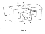
- a portion of a gas turbine 10 is provided and has a seal end attachment 11 to prevent leakage of working fluid of the gas turbine 10 resulting from differential thermal growth and to prevent compressor discharge air from mixing with and reducing the temperature of the working fluid resulting from differential thermal growth.
- the seal end attachment 11 includes a first vessel 20, such as an aft end of a transition piece, and a second vessel 30, such as a forward end of a stage 1 nozzle, although it is to be understood that the first and second vessels 20 and 30 may be any interfacing vessels where differential thermal growth occurs.
- the first vessel 20 and the second vessel 30 each form passages through which the working fluid sequentially flows.
- the first vessel 20 is formed to define a first recess 21 with a mating surface 22 and a shoulder surface 23.
- the first vessel 20 has an annular shape and the first recess 21 extends circumferentially along the circumferential length of the first vessel 20.
- the first recess 21 is formed with an angular G-shaped cross-section such that the mating surface 22 extends in the axial direction at an outer radial location and the shoulder surface 23 extends in the axial direction at an inner radial location.
- a radial sidewall 24 extends between the mating surface 22 and the shoulder surface 23 and a radial flange 25 extends radially from the shoulder surface 23 but does not reach the mating surface 22.
- the second vessel 30 is formed to define a second recess 31 with a mating surface 32 and a shoulder surface 33.
- the second vessel 30 has an annular shape and the second recess 31 extends circumferentially along the circumferential length of the second vessel 30.
- the second recess 31 is formed with a reversed angular G-shaped cross-section such that the mating surface 32 extends in the axial direction at an outer radial location and the shoulder surface 33 extends in the axial direction at an inner radial location.
- a radial sidewall 34 extends between the mating surface 32 and the shoulder surface 33 and a radial flange 35 extends radially from the shoulder surface 33 but does not reach the mating surface 32.
- first and second vessels 20 and 30 may each further include axial flanges 26 and 36 at one or both of an outer radial location and an inner radial location.
- the axial flanges 26 and 36 may serve to interfere with leakage flow propagating towards the seal end attachment 11.
- the seal end attachment 11 further includes a seal 40 having an outer surface 41 and an inner surface 42.
- the seal 40 is configured to prevent leakage of the working fluid as the working fluid flows through the first vessel 20 and into the second vessel 30.
- the seal 40 has an annular shape and extends between the first and second recesses 21 and 31 such that the outer surface 41 contacts the first and second mating surface 22 and 32. At an initial assembly time, the contact between the outer surface 41 and the first and second mating surfaces 22 and 32 may be relatively tight such that a seal is formed therebetween.
- the seal 40 includes a first annular flange 43 to contact the mating surface 22 of the first vessel 20, a second annular flange 44 to contact the mating surface 32 of the second vessel 30 and a central annular section 45 by which the first and second annular flanges 43 and 44 are connected to one another.
- the first and second annular flanges 43 and 44 may extend in opposite axial directions and, at least initially, may be coaxial.
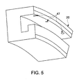
- the first and second annular flanges 43 and 44 may be further formed to define cooling locations 46 in agreement with cooling holes 47 (see FIG. 5 ) formed through the first and second vessels 20 and 30. As such, coolant may flow radially inwardly toward the mating surfaces 22 and 32 and the first and second annular flanges 43 and 44 to decrease temperatures thereof.
- the central annular section 45 may be formed to define a circumferential groove 460 by which differential thermal growth between the first and second vessels 20 and 30 may be absorbed. That is, as the first and second vessels 20 and 30 approach toward or recede from one another or move laterally or vertically with respect to one another due to differential thermal growth, the central annular section 45 may deform to prevent strain being applied to the first and second annular flanges 43 and 44, which may be sealed to the mating surfaces 22 and 32 as described herein.
- the circumferential groove 460 may be formed to bias the first and second annular flanges 43 and 44 into seal forming contact with the mating surfaces 22 and 32.
- the seal end attachment 11 further includes first and second pressing members 50 and 51, which are disposed within the first recess 21 of the first vessel 20 and the second recess 31 of the second vessel 30, respectively.
- Each of the first and second pressing members 50 and 51 is formed of materials that are more responsive to a condition than the materials of the first and second vessels 20 and 30 and, possibly the materials of the seal 40.
- the condition may be the exposure of first and second vessels 20 and 30 and seal 40 to high temperatures and pressures associated with or due to, for example, the passage of the working fluid through the first vessel 20, the seal 40 and the second vessel 30 where the working fluid includes products of combustion within the first vessel.
- These exemplary high temperatures and pressures may heat the first and second vessels 20 and 30, the seal 40 and the first and second pressing members 50 and 51 and thereby cause thermal expansion and/or deformation of the first and second vessels 20 and 30, the seal 40 and the first and second pressing members 50 and 51.
- CTE mean coefficient of thermal expansion
- each pressing member 50 and 51 is annular and ring-shaped and may be disposed within the first and second recess 21 and 31, respectively.
- the first pressing member 50 contacts the shoulder surface 23 and the inner surface 42 of the seal 40 at the first annular flange 43.
- the first pressing member 50 may also abut one or both of the radial sidewall 24 and the radial flange 25.
- the second pressing member 51 contacts the shoulder surface 33 and the inner surface 42 of the seal 40 at the second annular flange 44 and may also abut the radial sidewall 34 and the radial flange 35.
- first and second pressing members 50 and 51 are formed with spacing tolerances between one or both of the radial sidewalls 24, 34 and the radial flanges 25, 35 in order to permit axial thermal growth of the first and second pressing members 50 and 51.
- first and second pressing members 50 each have a higher mean CTE than those of the first and second vessels 20 and 30, the first and second pressing members 50 and 51 will tend to experience thermal expansion in the radial direction to a greater degree than the first vessel 20 or the second vessel 30 in the presence of the exemplary high temperature fluids such as those seen in a combustion zone of a gas turbine engine in operation.
- radial expansion of the first and second pressing members 50 and 51 will tend to exceed changes in radial separation between the mating surfaces 22, 32 and the shoulder surfaces 23, 33.
- the thermally grown first and second pressing members 50 and 51 will be squeezed between the shoulder surfaces 23, 33 and the mating surfaces 22, 32 with the first and second annular flanges 43 and 44 interposed therebetween.
- first and second pressing members 50 and 51 may each further include an axial flange 52, 53 to increase an area whereby the first and second pressing members 51 and 51 press upon the seal 40 toward the mating surfaces 23 and 33.
Landscapes
- Engineering & Computer Science (AREA)
- General Engineering & Computer Science (AREA)
- Mechanical Engineering (AREA)
- Gasket Seals (AREA)
- Turbine Rotor Nozzle Sealing (AREA)
Claims (11)
- Gasturbine (10), Folgendes umfassend:ein erstes und ein zweites Gefäß (20, 30), durch die nacheinander ein Arbeitsfluid strömt, wobei sowohl das erste als auch das zweite Gefäß (20, 30) so geformt sind, dass es jeweilige Aussparungen (21, 31) mit Pass- (22, 32) und Absatzflächen (23, 33) darin definiert, undeine Dichtungsendbefestigung (11), um ein Austreten von Arbeitsfluid aus der Gasturbine (10) zu verhindern, das sich aus einer unterschiedlichen Wärmeausdehnung des ersten und des zweiten Gefäßes (20, 30) ergibt, wobei die Dichtungsendbefestigung Folgendes umfasst:eine Dichtung (40), die sich zwischen den Aussparungen (21, 31) erstreckt, wobei die Dichtung einen ersten ringförmigen Flansch (43), der dafür konfiguriert ist, die Passfläche (22) der Aussparung des ersten Gefäßes (20) zu berühren, einen zweiten ringförmigen Flansch (44), der dafür konfiguriert ist, die Passfläche (32) der Aussparung des zweiten Gefäßes (30) zu berühren, und eine mittige ringförmige Sektion (45), durch die der erste und der zweite ringförmige Flansch (43, 44) verbunden sind, umfasst,ein erstes und ein zweites Presselement (50, 51), die innerhalb der Aussparungen (21, 31) des ersten beziehungsweise des zweiten Gefäßes (20, 30) angeordnet sind, wobei sowohl das erste als auch das zweite Presselement (50, 51) mehr als das erste und das zweite Gefäß (20, 30) auf einen Hochtemperaturzustand ansprechen, der verursacht wird durch den Durchfluss des Arbeitsfluids, der die jeweiligen Temperaturen des ersten und des zweiten Gefäßes (20, 30) und des ersten und des zweiten Presselements (50, 51) beeinflusst, und wobei sowohl das erste als auch das zweite Presselement (50, 51) so angeordnet sind, dass sie die jeweiligen Absatzflächen (23, 33) und die Dichtung (40) berühren, um als Reaktion auf den vorhandenen Zustand die Dichtung (40) gegen die jeweiligen Passflächen (22, 32) zu drücken, während sie von den jeweiligen Absatzflächen (23, 33) gestützt werden.
- Gasturbine (10) nach Anspruch 1, wobei das erste Gefäß (20) ein hinteres Ende eines Übergangsstücks umfasst.
- Gasturbine nach Anspruch 1 oder Anspruch 2, wobei das zweite Gefäß (30) ein vorderes Ende einer Erststufendüse umfasst.
- Gasturbine nach einem der Ansprüche 1 bis 3, wobei das erste und das zweite Gefäß (20, 30) und das erste und das zweite Presselement (50, 51) jeweils ringförmig sind.
- Gasturbine nach einem der Ansprüche 1 bis 4, wobei ein Werkstoff des Presselements (50, 51) einen höheren Wärmeausdehnungskoeffizienten hat als die jeweiligen Werkstoffe des ersten und des zweiten Gefäßes (20, 30).
- Gasturbine nach einem der Ansprüche 1 bis 5, wobei die Aussparung (21) des ersten Gefäßes (20) einen winkligen G-förmigen Querschnitt hat und die Aussparung (31) des zweiten Gefäßes (30) einen umgekehrt winkligen G-förmigen Querschnitt hat.
- Gasturbine nach einem der Ansprüche 1 bis 6, wobei das erste und das zweite Gefäß (20, 30) jeweils einen axialen Flansch (26, 36) umfassen.
- Gasturbine nach einem der Ansprüche 1 bis 7, wobei das erste und das zweite Presselement (50, 51) jeweils ringförmig sind.
- Gasturbine nach einem der Ansprüche 1 bis 8, wobei das erste und das zweite Presselement (50, 51) jeweils einen axialen Flansch (52, 53) umfassen.
- Gasturbine nach einem der Ansprüche 1 bis 9, wobei die mittige ringförmige Sektion (45) der Dichtung (40) so geformt ist, dass sie eine umlaufende Rille (460) definiert.
- Gasturbine nach einem der vorhergehenden Ansprüche, wobei der erste und der zweite axiale Flansch (43, 44) der Dichtung (40) so geformt sind, dass sie Kühlungspositionen (46) definieren.
Applications Claiming Priority (1)
| Application Number | Priority Date | Filing Date | Title |
|---|---|---|---|
| US13/210,902 US9353635B2 (en) | 2011-08-16 | 2011-08-16 | Seal end attachment |
Publications (2)
| Publication Number | Publication Date |
|---|---|
| EP2559859A1 EP2559859A1 (de) | 2013-02-20 |
| EP2559859B1 true EP2559859B1 (de) | 2014-03-26 |
Family
ID=46829629
Family Applications (1)
| Application Number | Title | Priority Date | Filing Date |
|---|---|---|---|
| EP12179887.0A Not-in-force EP2559859B1 (de) | 2011-08-16 | 2012-08-09 | Dichtungsendbefestigung |
Country Status (3)
| Country | Link |
|---|---|
| US (1) | US9353635B2 (de) |
| EP (1) | EP2559859B1 (de) |
| CN (1) | CN102953831B (de) |
Families Citing this family (17)
| Publication number | Priority date | Publication date | Assignee | Title |
|---|---|---|---|---|
| US9534783B2 (en) * | 2011-07-21 | 2017-01-03 | United Technologies Corporation | Insert adjacent to a heat shield element for a gas turbine engine combustor |
| FR2989426B1 (fr) * | 2012-04-11 | 2014-03-28 | Snecma | Turbomachine, telle qu'un turboreacteur ou un turbopropulseur d'avion |
| US9488110B2 (en) * | 2013-03-08 | 2016-11-08 | General Electric Company | Device and method for preventing leakage of air between multiple turbine components |
| WO2014186001A2 (en) * | 2013-04-12 | 2014-11-20 | United Technologies Corporation | Flexible feather seal for blade outer air seal gas turbine engine rapid response clearance control system |
| US9759427B2 (en) * | 2013-11-01 | 2017-09-12 | General Electric Company | Interface assembly for a combustor |
| CN104481701B (zh) * | 2014-10-28 | 2016-09-07 | 北京华清燃气轮机与煤气化联合循环工程技术有限公司 | 过渡段后密封结构 |
| US20160160667A1 (en) * | 2014-11-13 | 2016-06-09 | General Electric Company | Discourager seal for a turbine engine |
| US9759079B2 (en) | 2015-05-28 | 2017-09-12 | Rolls-Royce Corporation | Split line flow path seals |
| WO2018089014A1 (en) * | 2016-11-11 | 2018-05-17 | Siemens Aktiengesellschaft | Seal assembly between a transition duct and a stage one turbine vane structure |
| EP3421726B1 (de) * | 2017-06-30 | 2020-12-30 | Ansaldo Energia Switzerland AG | Bilderrahmen zur verbindung eines rohrbrenners mit einer gasturbine und gasturbine mit einem bilderrahmen |
| KR102038112B1 (ko) * | 2017-10-13 | 2019-10-29 | 두산중공업 주식회사 | 연소기 및 이를 포함하는 가스 터빈 |
| US10718226B2 (en) | 2017-11-21 | 2020-07-21 | Rolls-Royce Corporation | Ceramic matrix composite component assembly and seal |
| CN111750380B (zh) * | 2019-03-28 | 2021-09-21 | 中国航发湖南动力机械研究所 | 一种火焰筒出口连接装置 |
| EP3789638A1 (de) * | 2019-09-05 | 2021-03-10 | Siemens Aktiengesellschaft | Dichtung für verbrennungsvorrichtung |
| FR3100560B1 (fr) * | 2019-09-06 | 2022-04-29 | Safran Aircraft Engines | Ensemble pour une turbine de turbomachine |
| CN119778753B (zh) * | 2023-10-08 | 2025-11-25 | 中国航发商用航空发动机有限责任公司 | 燃气轮机及其燃烧室 |
| KR102898652B1 (ko) * | 2024-03-04 | 2025-12-24 | 대한민국(방위사업청장) | 커빅 커플링용 커빅 씰 및 이를 포함하는 커빅 커플링 |
Family Cites Families (43)
| Publication number | Priority date | Publication date | Assignee | Title |
|---|---|---|---|---|
| US3975114A (en) * | 1975-09-23 | 1976-08-17 | Westinghouse Electric Corporation | Seal arrangement for turbine diaphragms and the like |
| US4452462A (en) * | 1983-10-06 | 1984-06-05 | Gray Tool Company | Temperature resistant joint packing with E-shaped spring seal |
| DE3401569A1 (de) * | 1984-01-18 | 1985-07-25 | MTU Motoren- und Turbinen-Union München GmbH, 8000 München | Selbstwirkende spaltabdichtung |
| WO1992019891A2 (en) * | 1991-05-09 | 1992-11-12 | Bostec Engineering, Inc. | Gland and seal |
| US5169159A (en) | 1991-09-30 | 1992-12-08 | General Electric Company | Effective sealing device for engine flowpath |
| US5400586A (en) * | 1992-07-28 | 1995-03-28 | General Electric Co. | Self-accommodating brush seal for gas turbine combustor |
| WO1996006267A1 (en) | 1994-08-24 | 1996-02-29 | United Technologies Corporation | Rotatable seal element for a rotary machine |
| US5624227A (en) * | 1995-11-07 | 1997-04-29 | General Electric Co. | Seal for gas turbines |
| US6076835A (en) | 1997-05-21 | 2000-06-20 | Allison Advanced Development Company | Interstage van seal apparatus |
| GB9802761D0 (en) * | 1998-02-11 | 1998-04-08 | Raychem Sa Nv | Sealing arrangement |
| US6808179B1 (en) | 1998-07-31 | 2004-10-26 | Concepts Eti, Inc. | Turbomachinery seal |
| US6199871B1 (en) | 1998-09-02 | 2001-03-13 | General Electric Company | High excursion ring seal |
| DE10003728A1 (de) * | 2000-01-28 | 2001-08-09 | Siemens Ag | Hitzeschildanordnung für eine Heißgas führende Komponente, insbesondere für Strukturteile von Gasturbinen |
| JP4517325B2 (ja) * | 2000-10-05 | 2010-08-04 | 忠弘 大見 | 流体継手 |
| US6502825B2 (en) | 2000-12-26 | 2003-01-07 | General Electric Company | Pressure activated cloth seal |
| US6644667B2 (en) | 2001-02-23 | 2003-11-11 | Cmg Tech, Llc | Seal assembly and rotary machine containing such seal |
| US7578509B2 (en) | 2001-02-23 | 2009-08-25 | Cmg Tech, Llc | Seal assembly and rotary machine containing such seal |
| JP2002267023A (ja) * | 2001-03-13 | 2002-09-18 | Eagle Engineering Aerospace Co Ltd | ブラシシール装置 |
| US6547257B2 (en) * | 2001-05-04 | 2003-04-15 | General Electric Company | Combination transition piece floating cloth seal and stage 1 turbine nozzle flexible sealing element |
| US20030039542A1 (en) | 2001-08-21 | 2003-02-27 | Cromer Robert Harold | Transition piece side sealing element and turbine assembly containing such seal |
| US6637751B2 (en) * | 2001-12-28 | 2003-10-28 | General Electric Company | Supplemental seal for the chordal hinge seals in a gas turbine |
| US6994354B2 (en) * | 2002-01-15 | 2006-02-07 | Freudenberg-Nok General Partnership | Vibrationally decoupling gasket |
| RU2297566C2 (ru) * | 2002-07-03 | 2007-04-20 | Альстом Текнолоджи Лтд | Щелевое уплотнение для герметизации щели между двумя соседними конструкционными элементами |
| US6883807B2 (en) * | 2002-09-13 | 2005-04-26 | Seimens Westinghouse Power Corporation | Multidirectional turbine shim seal |
| GB0228748D0 (en) | 2002-12-10 | 2003-01-15 | Alstom Switzerland Ltd | Sealing arrangement |
| US7152864B2 (en) | 2003-10-02 | 2006-12-26 | Alstom Technology Ltd. | Seal assembly |
| US8695989B2 (en) * | 2004-04-30 | 2014-04-15 | Siemens Aktiengesellschaft | Hot gas seal |
| US7217081B2 (en) * | 2004-10-15 | 2007-05-15 | Siemens Power Generation, Inc. | Cooling system for a seal for turbine vane shrouds |
| US7600649B1 (en) | 2005-02-08 | 2009-10-13 | Baker Hughes Incorporated | Methods and devices for preventing extrusion failure of o-ring seal assemblies |
| US20070024007A1 (en) * | 2005-07-28 | 2007-02-01 | Putch Samuel W | Seal ring and method |
| US7788932B2 (en) | 2005-08-23 | 2010-09-07 | Mitsubishi Heavy Industries, Ltd. | Seal structure for gas turbine combustor |
| US7845649B2 (en) * | 2005-09-30 | 2010-12-07 | General Electric Company | Methods and apparatus to facilitate sealing high pressure joints |
| US20070114727A1 (en) * | 2005-11-21 | 2007-05-24 | General Electric Company | Seal member, assembly and method |
| US7771159B2 (en) | 2006-10-16 | 2010-08-10 | General Electric Company | High temperature seals and high temperature sealing systems |
| US7967297B2 (en) * | 2007-03-13 | 2011-06-28 | Eaton Corporation | Thermally-activated control gap brush seal |
| US7828302B2 (en) * | 2007-08-15 | 2010-11-09 | Federal-Mogul Corporation | Lateral sealing gasket and method |
| US20090115141A1 (en) | 2007-11-07 | 2009-05-07 | General Electric Company | Stage one nozzle to transition piece seal |
| DE102007062681A1 (de) | 2007-12-24 | 2009-06-25 | Man Turbo Ag | Dichtsegment sowie Dichtsegmentenanordnung |
| JP4884410B2 (ja) * | 2008-03-04 | 2012-02-29 | 株式会社日立製作所 | 二軸ガスタービン |
| US8210799B1 (en) * | 2008-03-31 | 2012-07-03 | Florida Turbine Technologies, Inc. | Bi-metallic strip seal for a turbine shroud |
| US8262349B2 (en) | 2008-12-22 | 2012-09-11 | General Electric Company | Adaptive compliant plate seal assemblies and methods |
| US8382424B1 (en) * | 2010-05-18 | 2013-02-26 | Florida Turbine Technologies, Inc. | Turbine vane mate face seal pin with impingement cooling |
| US8678754B2 (en) * | 2011-01-24 | 2014-03-25 | General Electric Company | Assembly for preventing fluid flow |
-
2011
- 2011-08-16 US US13/210,902 patent/US9353635B2/en not_active Expired - Fee Related
-
2012
- 2012-08-09 EP EP12179887.0A patent/EP2559859B1/de not_active Not-in-force
- 2012-08-16 CN CN201210291821.6A patent/CN102953831B/zh not_active Expired - Fee Related
Also Published As
| Publication number | Publication date |
|---|---|
| US9353635B2 (en) | 2016-05-31 |
| CN102953831A (zh) | 2013-03-06 |
| CN102953831B (zh) | 2016-07-13 |
| US20130042631A1 (en) | 2013-02-21 |
| EP2559859A1 (de) | 2013-02-20 |
Similar Documents
| Publication | Publication Date | Title |
|---|---|---|
| EP2559859B1 (de) | Dichtungsendbefestigung | |
| US8573603B2 (en) | Split ring seal with spring element | |
| US9394799B1 (en) | Air riding seal for a turbine | |
| CN105736701B (zh) | 拱形结合环形密封件及具有该环形密封件的环密封系统 | |
| US4921401A (en) | Casting for a rotary machine | |
| US20140023490A1 (en) | Fastener | |
| US9670791B2 (en) | Flexible finger seal for sealing a gap between turbine engine components | |
| EP2813670B1 (de) | Dichtungsstruktur zwischen stationären Bauteilen | |
| US10240473B2 (en) | Bifurcated sliding seal | |
| US9932849B2 (en) | Fluid seal structure of heat engine including steam turbine | |
| WO2017081810A1 (ja) | 遠心圧縮機 | |
| EP2812556A2 (de) | Kanalisierte federdichtung zur abdichtung eines luftspaltes zwischen beweglichen platten | |
| EP3048344B1 (de) | Dichtungsgehäuse-vorverjüngung | |
| CN109707468B (zh) | 一种应用于静止机匣间的高效封严结构 | |
| US20160169023A1 (en) | Sealing Device, Rotating Machine, and Method for Manufacturing Sealing Device | |
| CN105917082B (zh) | 用于燃气涡轮发动机中相邻的过渡导管的出口部分之间间隙的密封组件 | |
| EP2977653B1 (de) | Leckagepräventionsdichtung und pumpe für kernreaktorkühlmaterial | |
| US7347662B2 (en) | Sealing arrangement | |
| EP3047130B1 (de) | Gas turbinen dichtungsanordnung welche wabendichtungen mit keilprofil beinhaltet | |
| US10920670B2 (en) | Sealing device arrangement at the interface between a combustor and a turbine of a gas turbine and gas turbine with such a sealing arrangement | |
| JP2014125986A (ja) | シール装置、およびそれを用いた回転機械 | |
| EP3798426B1 (de) | Kohlenstoffdichtungsanordnung | |
| EP3039316B1 (de) | Gleitdichtung | |
| US20210285331A1 (en) | Turbine stator blade | |
| EP3020928B1 (de) | Dichtungsstruktur und turbine |
Legal Events
| Date | Code | Title | Description |
|---|---|---|---|
| PUAI | Public reference made under article 153(3) epc to a published international application that has entered the european phase |
Free format text: ORIGINAL CODE: 0009012 |
|
| AK | Designated contracting states |
Kind code of ref document: A1 Designated state(s): AL AT BE BG CH CY CZ DE DK EE ES FI FR GB GR HR HU IE IS IT LI LT LU LV MC MK MT NL NO PL PT RO RS SE SI SK SM TR |
|
| AX | Request for extension of the european patent |
Extension state: BA ME |
|
| 17P | Request for examination filed |
Effective date: 20130820 |
|
| RBV | Designated contracting states (corrected) |
Designated state(s): AL AT BE BG CH CY CZ DE DK EE ES FI FR GB GR HR HU IE IS IT LI LT LU LV MC MK MT NL NO PL PT RO RS SE SI SK SM TR |
|
| GRAP | Despatch of communication of intention to grant a patent |
Free format text: ORIGINAL CODE: EPIDOSNIGR1 |
|
| RIC1 | Information provided on ipc code assigned before grant |
Ipc: F01D 9/02 20060101ALI20130919BHEP Ipc: F16J 15/06 20060101ALI20130919BHEP Ipc: F01D 11/00 20060101AFI20130919BHEP Ipc: F16J 15/08 20060101ALI20130919BHEP |
|
| INTG | Intention to grant announced |
Effective date: 20131022 |
|
| GRAS | Grant fee paid |
Free format text: ORIGINAL CODE: EPIDOSNIGR3 |
|
| GRAA | (expected) grant |
Free format text: ORIGINAL CODE: 0009210 |
|
| AK | Designated contracting states |
Kind code of ref document: B1 Designated state(s): AL AT BE BG CH CY CZ DE DK EE ES FI FR GB GR HR HU IE IS IT LI LT LU LV MC MK MT NL NO PL PT RO RS SE SI SK SM TR |
|
| REG | Reference to a national code |
Ref country code: GB Ref legal event code: FG4D |
|
| REG | Reference to a national code |
Ref country code: CH Ref legal event code: EP |
|
| REG | Reference to a national code |
Ref country code: AT Ref legal event code: REF Ref document number: 659132 Country of ref document: AT Kind code of ref document: T Effective date: 20140415 |
|
| REG | Reference to a national code |
Ref country code: IE Ref legal event code: FG4D |
|
| REG | Reference to a national code |
Ref country code: DE Ref legal event code: R096 Ref document number: 602012001210 Country of ref document: DE Effective date: 20140508 |
|
| PG25 | Lapsed in a contracting state [announced via postgrant information from national office to epo] |
Ref country code: LT Free format text: LAPSE BECAUSE OF FAILURE TO SUBMIT A TRANSLATION OF THE DESCRIPTION OR TO PAY THE FEE WITHIN THE PRESCRIBED TIME-LIMIT Effective date: 20140326 Ref country code: NO Free format text: LAPSE BECAUSE OF FAILURE TO SUBMIT A TRANSLATION OF THE DESCRIPTION OR TO PAY THE FEE WITHIN THE PRESCRIBED TIME-LIMIT Effective date: 20140626 |
|
| REG | Reference to a national code |
Ref country code: AT Ref legal event code: MK05 Ref document number: 659132 Country of ref document: AT Kind code of ref document: T Effective date: 20140326 |
|
| REG | Reference to a national code |
Ref country code: NL Ref legal event code: VDEP Effective date: 20140326 |
|
| REG | Reference to a national code |
Ref country code: LT Ref legal event code: MG4D |
|
| PG25 | Lapsed in a contracting state [announced via postgrant information from national office to epo] |
Ref country code: FI Free format text: LAPSE BECAUSE OF FAILURE TO SUBMIT A TRANSLATION OF THE DESCRIPTION OR TO PAY THE FEE WITHIN THE PRESCRIBED TIME-LIMIT Effective date: 20140326 Ref country code: SE Free format text: LAPSE BECAUSE OF FAILURE TO SUBMIT A TRANSLATION OF THE DESCRIPTION OR TO PAY THE FEE WITHIN THE PRESCRIBED TIME-LIMIT Effective date: 20140326 |
|
| PG25 | Lapsed in a contracting state [announced via postgrant information from national office to epo] |
Ref country code: LV Free format text: LAPSE BECAUSE OF FAILURE TO SUBMIT A TRANSLATION OF THE DESCRIPTION OR TO PAY THE FEE WITHIN THE PRESCRIBED TIME-LIMIT Effective date: 20140326 Ref country code: HR Free format text: LAPSE BECAUSE OF FAILURE TO SUBMIT A TRANSLATION OF THE DESCRIPTION OR TO PAY THE FEE WITHIN THE PRESCRIBED TIME-LIMIT Effective date: 20140326 Ref country code: RS Free format text: LAPSE BECAUSE OF FAILURE TO SUBMIT A TRANSLATION OF THE DESCRIPTION OR TO PAY THE FEE WITHIN THE PRESCRIBED TIME-LIMIT Effective date: 20140326 |
|
| PG25 | Lapsed in a contracting state [announced via postgrant information from national office to epo] |
Ref country code: CY Free format text: LAPSE BECAUSE OF FAILURE TO SUBMIT A TRANSLATION OF THE DESCRIPTION OR TO PAY THE FEE WITHIN THE PRESCRIBED TIME-LIMIT Effective date: 20140326 Ref country code: EE Free format text: LAPSE BECAUSE OF FAILURE TO SUBMIT A TRANSLATION OF THE DESCRIPTION OR TO PAY THE FEE WITHIN THE PRESCRIBED TIME-LIMIT Effective date: 20140326 Ref country code: RO Free format text: LAPSE BECAUSE OF FAILURE TO SUBMIT A TRANSLATION OF THE DESCRIPTION OR TO PAY THE FEE WITHIN THE PRESCRIBED TIME-LIMIT Effective date: 20140326 Ref country code: IS Free format text: LAPSE BECAUSE OF FAILURE TO SUBMIT A TRANSLATION OF THE DESCRIPTION OR TO PAY THE FEE WITHIN THE PRESCRIBED TIME-LIMIT Effective date: 20140726 Ref country code: BE Free format text: LAPSE BECAUSE OF FAILURE TO SUBMIT A TRANSLATION OF THE DESCRIPTION OR TO PAY THE FEE WITHIN THE PRESCRIBED TIME-LIMIT Effective date: 20140326 Ref country code: CZ Free format text: LAPSE BECAUSE OF FAILURE TO SUBMIT A TRANSLATION OF THE DESCRIPTION OR TO PAY THE FEE WITHIN THE PRESCRIBED TIME-LIMIT Effective date: 20140326 Ref country code: BG Free format text: LAPSE BECAUSE OF FAILURE TO SUBMIT A TRANSLATION OF THE DESCRIPTION OR TO PAY THE FEE WITHIN THE PRESCRIBED TIME-LIMIT Effective date: 20140626 Ref country code: NL Free format text: LAPSE BECAUSE OF FAILURE TO SUBMIT A TRANSLATION OF THE DESCRIPTION OR TO PAY THE FEE WITHIN THE PRESCRIBED TIME-LIMIT Effective date: 20140326 |
|
| PG25 | Lapsed in a contracting state [announced via postgrant information from national office to epo] |
Ref country code: PL Free format text: LAPSE BECAUSE OF FAILURE TO SUBMIT A TRANSLATION OF THE DESCRIPTION OR TO PAY THE FEE WITHIN THE PRESCRIBED TIME-LIMIT Effective date: 20140326 Ref country code: AT Free format text: LAPSE BECAUSE OF FAILURE TO SUBMIT A TRANSLATION OF THE DESCRIPTION OR TO PAY THE FEE WITHIN THE PRESCRIBED TIME-LIMIT Effective date: 20140326 Ref country code: ES Free format text: LAPSE BECAUSE OF FAILURE TO SUBMIT A TRANSLATION OF THE DESCRIPTION OR TO PAY THE FEE WITHIN THE PRESCRIBED TIME-LIMIT Effective date: 20140326 Ref country code: SK Free format text: LAPSE BECAUSE OF FAILURE TO SUBMIT A TRANSLATION OF THE DESCRIPTION OR TO PAY THE FEE WITHIN THE PRESCRIBED TIME-LIMIT Effective date: 20140326 |
|
| PG25 | Lapsed in a contracting state [announced via postgrant information from national office to epo] |
Ref country code: PT Free format text: LAPSE BECAUSE OF FAILURE TO SUBMIT A TRANSLATION OF THE DESCRIPTION OR TO PAY THE FEE WITHIN THE PRESCRIBED TIME-LIMIT Effective date: 20140728 |
|
| REG | Reference to a national code |
Ref country code: DE Ref legal event code: R097 Ref document number: 602012001210 Country of ref document: DE |
|
| PG25 | Lapsed in a contracting state [announced via postgrant information from national office to epo] |
Ref country code: DK Free format text: LAPSE BECAUSE OF FAILURE TO SUBMIT A TRANSLATION OF THE DESCRIPTION OR TO PAY THE FEE WITHIN THE PRESCRIBED TIME-LIMIT Effective date: 20140326 |
|
| PLBE | No opposition filed within time limit |
Free format text: ORIGINAL CODE: 0009261 |
|
| STAA | Information on the status of an ep patent application or granted ep patent |
Free format text: STATUS: NO OPPOSITION FILED WITHIN TIME LIMIT |
|
| 26N | No opposition filed |
Effective date: 20150106 |
|
| PG25 | Lapsed in a contracting state [announced via postgrant information from national office to epo] |
Ref country code: LU Free format text: LAPSE BECAUSE OF FAILURE TO SUBMIT A TRANSLATION OF THE DESCRIPTION OR TO PAY THE FEE WITHIN THE PRESCRIBED TIME-LIMIT Effective date: 20140809 Ref country code: MC Free format text: LAPSE BECAUSE OF FAILURE TO SUBMIT A TRANSLATION OF THE DESCRIPTION OR TO PAY THE FEE WITHIN THE PRESCRIBED TIME-LIMIT Effective date: 20140326 Ref country code: IT Free format text: LAPSE BECAUSE OF FAILURE TO SUBMIT A TRANSLATION OF THE DESCRIPTION OR TO PAY THE FEE WITHIN THE PRESCRIBED TIME-LIMIT Effective date: 20140326 |
|
| REG | Reference to a national code |
Ref country code: DE Ref legal event code: R097 Ref document number: 602012001210 Country of ref document: DE Effective date: 20150106 |
|
| REG | Reference to a national code |
Ref country code: IE Ref legal event code: MM4A |
|
| REG | Reference to a national code |
Ref country code: FR Ref legal event code: ST Effective date: 20150430 |
|
| PG25 | Lapsed in a contracting state [announced via postgrant information from national office to epo] |
Ref country code: SI Free format text: LAPSE BECAUSE OF FAILURE TO SUBMIT A TRANSLATION OF THE DESCRIPTION OR TO PAY THE FEE WITHIN THE PRESCRIBED TIME-LIMIT Effective date: 20140326 |
|
| PG25 | Lapsed in a contracting state [announced via postgrant information from national office to epo] |
Ref country code: IE Free format text: LAPSE BECAUSE OF NON-PAYMENT OF DUE FEES Effective date: 20140809 Ref country code: FR Free format text: LAPSE BECAUSE OF NON-PAYMENT OF DUE FEES Effective date: 20140901 |
|
| PG25 | Lapsed in a contracting state [announced via postgrant information from national office to epo] |
Ref country code: SM Free format text: LAPSE BECAUSE OF FAILURE TO SUBMIT A TRANSLATION OF THE DESCRIPTION OR TO PAY THE FEE WITHIN THE PRESCRIBED TIME-LIMIT Effective date: 20140326 |
|
| PG25 | Lapsed in a contracting state [announced via postgrant information from national office to epo] |
Ref country code: MT Free format text: LAPSE BECAUSE OF FAILURE TO SUBMIT A TRANSLATION OF THE DESCRIPTION OR TO PAY THE FEE WITHIN THE PRESCRIBED TIME-LIMIT Effective date: 20140326 Ref country code: GR Free format text: LAPSE BECAUSE OF FAILURE TO SUBMIT A TRANSLATION OF THE DESCRIPTION OR TO PAY THE FEE WITHIN THE PRESCRIBED TIME-LIMIT Effective date: 20140627 |
|
| PG25 | Lapsed in a contracting state [announced via postgrant information from national office to epo] |
Ref country code: HU Free format text: LAPSE BECAUSE OF FAILURE TO SUBMIT A TRANSLATION OF THE DESCRIPTION OR TO PAY THE FEE WITHIN THE PRESCRIBED TIME-LIMIT; INVALID AB INITIO Effective date: 20120809 Ref country code: TR Free format text: LAPSE BECAUSE OF FAILURE TO SUBMIT A TRANSLATION OF THE DESCRIPTION OR TO PAY THE FEE WITHIN THE PRESCRIBED TIME-LIMIT Effective date: 20140326 |
|
| PGFP | Annual fee paid to national office [announced via postgrant information from national office to epo] |
Ref country code: GB Payment date: 20160830 Year of fee payment: 5 Ref country code: CH Payment date: 20160829 Year of fee payment: 5 Ref country code: DE Payment date: 20160826 Year of fee payment: 5 |
|
| REG | Reference to a national code |
Ref country code: DE Ref legal event code: R119 Ref document number: 602012001210 Country of ref document: DE |
|
| REG | Reference to a national code |
Ref country code: CH Ref legal event code: PL |
|
| GBPC | Gb: european patent ceased through non-payment of renewal fee |
Effective date: 20170809 |
|
| PG25 | Lapsed in a contracting state [announced via postgrant information from national office to epo] |
Ref country code: CH Free format text: LAPSE BECAUSE OF NON-PAYMENT OF DUE FEES Effective date: 20170831 Ref country code: LI Free format text: LAPSE BECAUSE OF NON-PAYMENT OF DUE FEES Effective date: 20170831 |
|
| PG25 | Lapsed in a contracting state [announced via postgrant information from national office to epo] |
Ref country code: MK Free format text: LAPSE BECAUSE OF FAILURE TO SUBMIT A TRANSLATION OF THE DESCRIPTION OR TO PAY THE FEE WITHIN THE PRESCRIBED TIME-LIMIT Effective date: 20140326 |
|
| PG25 | Lapsed in a contracting state [announced via postgrant information from national office to epo] |
Ref country code: DE Free format text: LAPSE BECAUSE OF NON-PAYMENT OF DUE FEES Effective date: 20180301 Ref country code: GB Free format text: LAPSE BECAUSE OF NON-PAYMENT OF DUE FEES Effective date: 20170809 |
|
| PG25 | Lapsed in a contracting state [announced via postgrant information from national office to epo] |
Ref country code: AL Free format text: LAPSE BECAUSE OF FAILURE TO SUBMIT A TRANSLATION OF THE DESCRIPTION OR TO PAY THE FEE WITHIN THE PRESCRIBED TIME-LIMIT Effective date: 20140326 |