EP2559962A2 - Abgaswärmeübertrager - Google Patents
Abgaswärmeübertrager Download PDFInfo
- Publication number
- EP2559962A2 EP2559962A2 EP12180174A EP12180174A EP2559962A2 EP 2559962 A2 EP2559962 A2 EP 2559962A2 EP 12180174 A EP12180174 A EP 12180174A EP 12180174 A EP12180174 A EP 12180174A EP 2559962 A2 EP2559962 A2 EP 2559962A2
- Authority
- EP
- European Patent Office
- Prior art keywords
- heat exchanger
- coolant
- exhaust
- exhaust gas
- housing
- Prior art date
- Legal status (The legal status is an assumption and is not a legal conclusion. Google has not performed a legal analysis and makes no representation as to the accuracy of the status listed.)
- Granted
Links
Images




Classifications
-
- F—MECHANICAL ENGINEERING; LIGHTING; HEATING; WEAPONS; BLASTING
- F28—HEAT EXCHANGE IN GENERAL
- F28F—DETAILS OF HEAT-EXCHANGE AND HEAT-TRANSFER APPARATUS, OF GENERAL APPLICATION
- F28F9/00—Casings; Header boxes; Auxiliary supports for elements; Auxiliary members within casings
- F28F9/005—Other auxiliary members within casings, e.g. internal filling means or sealing means
-
- F—MECHANICAL ENGINEERING; LIGHTING; HEATING; WEAPONS; BLASTING
- F02—COMBUSTION ENGINES; HOT-GAS OR COMBUSTION-PRODUCT ENGINE PLANTS
- F02M—SUPPLYING COMBUSTION ENGINES IN GENERAL WITH COMBUSTIBLE MIXTURES OR CONSTITUENTS THEREOF
- F02M26/00—Engine-pertinent apparatus for adding exhaust gases to combustion-air, main fuel or fuel-air mixture, e.g. by exhaust gas recirculation [EGR] systems
- F02M26/13—Arrangement or layout of EGR passages, e.g. in relation to specific engine parts or for incorporation of accessories
- F02M26/22—Arrangement or layout of EGR passages, e.g. in relation to specific engine parts or for incorporation of accessories with coolers in the recirculation passage
- F02M26/23—Layout, e.g. schematics
- F02M26/28—Layout, e.g. schematics with liquid-cooled heat exchangers
-
- F—MECHANICAL ENGINEERING; LIGHTING; HEATING; WEAPONS; BLASTING
- F28—HEAT EXCHANGE IN GENERAL
- F28D—HEAT-EXCHANGE APPARATUS, NOT PROVIDED FOR IN ANOTHER SUBCLASS, IN WHICH THE HEAT-EXCHANGE MEDIA DO NOT COME INTO DIRECT CONTACT
- F28D7/00—Heat-exchange apparatus having stationary tubular conduit assemblies for both heat-exchange media, the media being in contact with different sides of a conduit wall
- F28D7/16—Heat-exchange apparatus having stationary tubular conduit assemblies for both heat-exchange media, the media being in contact with different sides of a conduit wall the conduits being arranged in parallel spaced relation
- F28D7/1684—Heat-exchange apparatus having stationary tubular conduit assemblies for both heat-exchange media, the media being in contact with different sides of a conduit wall the conduits being arranged in parallel spaced relation the conduits having a non-circular cross-section
-
- F—MECHANICAL ENGINEERING; LIGHTING; HEATING; WEAPONS; BLASTING
- F28—HEAT EXCHANGE IN GENERAL
- F28F—DETAILS OF HEAT-EXCHANGE AND HEAT-TRANSFER APPARATUS, OF GENERAL APPLICATION
- F28F9/00—Casings; Header boxes; Auxiliary supports for elements; Auxiliary members within casings
- F28F9/02—Header boxes; End plates
- F28F9/026—Header boxes; End plates with static flow control means, e.g. with means for uniformly distributing heat exchange media into conduits
-
- F—MECHANICAL ENGINEERING; LIGHTING; HEATING; WEAPONS; BLASTING
- F28—HEAT EXCHANGE IN GENERAL
- F28F—DETAILS OF HEAT-EXCHANGE AND HEAT-TRANSFER APPARATUS, OF GENERAL APPLICATION
- F28F9/00—Casings; Header boxes; Auxiliary supports for elements; Auxiliary members within casings
- F28F9/22—Arrangements for directing heat-exchange media into successive compartments, e.g. arrangements of guide plates
-
- F—MECHANICAL ENGINEERING; LIGHTING; HEATING; WEAPONS; BLASTING
- F01—MACHINES OR ENGINES IN GENERAL; ENGINE PLANTS IN GENERAL; STEAM ENGINES
- F01N—GAS-FLOW SILENCERS OR EXHAUST APPARATUS FOR MACHINES OR ENGINES IN GENERAL; GAS-FLOW SILENCERS OR EXHAUST APPARATUS FOR INTERNAL-COMBUSTION ENGINES
- F01N2240/00—Combination or association of two or more different exhaust treating devices, or of at least one such device with an auxiliary device, not covered by indexing codes F01N2230/00 or F01N2250/00, one of the devices being
- F01N2240/02—Combination or association of two or more different exhaust treating devices, or of at least one such device with an auxiliary device, not covered by indexing codes F01N2230/00 or F01N2250/00, one of the devices being a heat exchanger
Definitions
- the invention relates to an exhaust gas heat exchanger, comprising a tube bundle with exhaust-carrying tubes and a through-flow of a coolant housing, which encloses the tube bundle and having a coolant inlet and a coolant outlet.
- Exhaust heat exchangers are preferably used in motor vehicles, where they are arranged on the internal combustion engine, cool the hot, exhausted from the engine exhaust and feed the internal combustion engine again.
- Exhaust gas heat exchangers are known, which have a tube bundle with exhaust pipes, which is enclosed by a housing through which a coolant flows. The heat of the exhaust gas is released to the coolant. The coolant passes through a coolant inlet into the interior of the housing and leaves after flowing through the tube bundle via a, also formed on the housing coolant outlet the exhaust gas heat exchanger.
- the invention is therefore based on the object to provide an exhaust gas heat exchanger, in which regardless of the position of the coolant inlet or thedemitelauslasses the coolant is optimally passed through the exhaust gas heat exchanger, so that an optimal coolant distribution over the entire tube bundle is guaranteed.
- the object is achieved in that between the tube bundle and the housing for adjusting a coolant channel at least a three-dimensionaldovleit Nurs is formed, wherein the coolant inlet opens into the coolant channel.
- This has the advantage that the coolant is first conducted past the tube bundle in a coolant channel and then on the return path to the tube bundle is fed, wherein the coolant detects all the tubes of the tube bundle evenly.
- a uniform coolant supply is made possible, whereby an optimal performance of the exhaust gas heat exchanger is ensured. This occurs regardless of the positions of the coolant inlet and the coolant outlet.
- the three-dimensionalisserleit if the tubes of the tube bundle have a polygonal cross section, which are used in a non-angular housing, the three-dimensionaldeffenleitSENSE the channels are closed, which can lead to uncontrolled bypasses. A short circuit in the coolant circuit is thus reliably prevented.
- the three-dimensionaldeffenleit serves as a separator for the coolant and is depending on how the coolant inlet and the coolant outlet to each other, so constructed that an optimal coolant flow is ensured in the exhaust gas heat exchanger.
- thedeffenleit founded the tube bundle completely, wherein approximately perpendicular to the coolant channel with a predetermined distance from theisserstoffleit Anlagen, a, the housing occlusive bottom is formed.
- the bottom in which the exhaust-gas-carrying tubes are embedded, it is ensured that the coolant, which flows into the housing via the coolant inlet and the coolant channel extending outside the tube bundle, is deflected in the direction of the tubes by approximately 180 °.
- the coolant flows evenly around all the exhaust pipes. This ensures a defined guidance of the coolant flow.
- thedeschleit In a variant, thedeatorial procedure, thedeabaleit adopted at least one spacer, which extends at an angle ⁇ 90 °, starting from a, the bottom opposite edge of thedestoffleit observed in the direction of the bottom.
- thedeschleit By means of this flat spacer, thedeschleit noise is fixed to the ground, thereby ensuring a stable support of theméstoffleit recognized within the Abgasebenstedtragers becomes.
- the deflecting of the cooling liquid in the direction of the pipes carrying the exhaust gas is assisted by the spacer.
- the coolant-conducting device has a polygonal cross-section, wherein the corners of the cross-section of the coolant-conducting device touch the housing.
- the corners thus assume the task of a wide attachment of theisserffenleit Huawei to the housing.
- thedeffenleit After inserting thedeatorileit adopted in the housing of the exhaust gas heat exchanger, thedeffenleit Huawei is positioned by means of the corners on the housing and at the same time fixed to the ground with the spacers.
- thedemiflelleit responded closes by their contour, the channels that arise through the use of rectangular tubes in the non-rectangular housing. As a result, an optimal coolant flow is achieved in the tube bundle, whereby the exhaust gas heat exchanger achieves optimum performance.
- a Abgasumlenkaku is arranged on the housing in the exhaust gas outlet, the lowest point is inside spanned by a shielding. This ensures that a condensate, which can settle especially at standstill of the engine and frozen in the worst case at very cold outside temperatures occurs as a solid, not at the deepest and coolest point attaches and can be carried by the exhaust. Due to the shielding element on which the condensate settles, the condensate is heated as long as due to its central positioning in the exhaust gas during operation of the internal combustion engine until the condensate is evaporated and transported in the gaseous state from the exhaust gas heat exchanger.
- Damage to the internal combustion engine or of the internal combustion engine upstream turbocharger due to smallest condensate droplets or ice particles are thus reliably prevented.
- a malfunction of the entire internal combustion engine due to the impact of the condensate on the Turbocharger is excluded. Further transport of the condensate in the form of a solid in the hot exhaust gas is reliably prevented.
- the approximately planar shielding element covers a circular arc of the cylinder-like Abgasumlenkmaschine containing the lowest point, wherein the shielding connected at its ends to the Abgasumlenkmaschine, in particular welded or soldered is.
- the exhaust gas flows around the shielding from all sides. Characterized in that the condensate is heated on the shielding by the exhaust gas, it is again transferred to the gaseous state and can leave the engine with the exhaust gas without further damage.
- the shielding element has fixing elements for securing the shielding element to the exhaust deflecting unit at the ends lying opposite the exhaust-deflecting unit.
- the shielding element according to the invention is structurally simple and inexpensive to produce. Constructive measures on the housing of the Abgasumlenkong to prevent removal of the condensate can thus be omitted.
- the exhaust deflecting unit and the shielding element are integrally formed as a cast part. This allows a particularly cost-effective production, since two components are produced simultaneously in one process step, wherein the shielding is an integral part of the Abgasumlenkaku.
- At least two exhaust gas outlet nozzles preferably on the Abgasumlenkica formed. Due to the arrangement of at least two exhaust gas outlet, the exhaust gas can simultaneously several lines are discharged.
- the use of multiple exhaust spouts prevents the use of additional components having a sander function after the exhaust gas heat exchanger to realize that the exhaust gas exiting the exhaust gas heat exchanger is split and directed in different directions of the motor vehicle. This results in cost advantages, since components with Verteiterfunktion omitted.
- By attaching the exhaust outlet can influence the speed distribution and temperature distribution of the exhaust gas in and after the exhaust gas heat exchanger influence.
- At least two exhaust gas inlet nozzles are present. Even with the use of more than two exhaust inlet connection components are saved with collecting function before the exhaust gas heat exchanger.
- Several supply lines can be guided directly from the engine to the exhaust gas heat exchanger, which is particularly useful when the engine consists of two engine blocks, each of which engine block an exhaust pipe is fed to the exhaust gas heat exchanger.
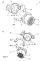
- the exhaust heat exchanger 1 has a housing 2, which comprises a coolant inlet 3 and a coolant outlet 4.
- the coolant inlet 3 is arranged rotated by 90 ° to the coolant outlet 4.
- the housing 2 is preferably of cylindrical construction and accommodates a cooling means 5 in its interior.
- Thisdeatorileit Huawei 5 is partially inside the housing 2.
- said tube bundle tubes 15 FIG. 3
- Thedeatorileit Huawei 5 is thus arranged between the tube bundle and the housing 2, wherein theisserleit responded 5 completely surrounds the tube bundle.
- Such an exhaust gas heat exchanger 1 is connected to the internal combustion engine, so that the exhaust gases take the shortest possible way to the exhaust gas heat exchanger 1.
- FIG. 2 is a cross section through the, in FIG. 1 illustrated exhaust gas heat exchanger 1 shown.
- the round cross-section of the housing 2 can be seen, in which extends thedeffenleit Road 5, which in turn has an octagonal cross-section.
- the corners 23 formed in the octagonal cross section form edges in the longitudinal extent of the coolant guide device 5, which abut against the inner wall of the housing 2.
- the octagonal cross section of thedeschleit Vietnamese 5 forms between the housing 2 and thederichtelleiteirlides 5 two coolant channels 6 and 7 by the rounding of the housing 2 is covered by a flat surface of theméstoffleit driven 5.
- the channels 6 and 7 are opposite each other.
- the channels 6, 7 arranged outside the tube bundle serve to introduce the coolant into the housing 2.
- a spacer 10, 11, 12, 13 is in each case formed between one of the channels 6 or 7 and a channel end 8, 9 of the coolant guide device 5.
- spacers 10, 11, 12, 13 are each formed two mirror-symmetrical to each other and extend from the edge of thedemihelleit disturbed 5 in the direction of a bottom 16 (FIG. FIG. 3 ), which closes the housing 2.
- the attached at the edge of thedemifteelleit Vietnamese 5 and flat spacers 10, 11, 12, 13 are bent starting from the edge of thedeffenleit responded 5 by less than 90 ° inwards and touch with their ends the bottom 16, whereby thedestoffleit responded 5 on the Floor 16 is fixed. Since thedeatorileit responded 5 is fixed with the corners 23 of their Querterrorismstes on the housing 2 at the same time, a stable positioning of thedemitelleit Nur 5 is realized within the housing 2 of the exhaust gas heat exchanger 1.
- Such an exhaust heat exchanger 1 is connected to the internal combustion engine, wherein the exhaust gases emitted by the internal combustion engine flow into the tubes 5 of the tube bundle, which is mounted within the coolant guide device 5.
- the coolant inlet 3 is connected to the channels 6 and 7, wherein the Kühtmittetfeit Huawei 5 opposite thedemitelauslast 4 is closed behind the coolant inlet 3 in the direction of the exhaust outlet.
- FIG. 1b can be seen where the completion of thedeticaleit worn 5 is realized by bent ends 14.
- the coolant which flows through thedemiteleinlass 3 in the channels 6 and 7, only in one direction between the housing 2 and themémail lead device 5 to flow.
- the coolant reaches the edge of the coolant supply device 5, which faces the bottom 16 and in which a predetermined distance between the edge of the coolant guide device 5 and the bottom 16 is set by the spacers 10, 11, 12, 13, then the coolant is removed from the channels 6 and 7 deflected in the reverse direction and flows through the tube bundle in the opposite direction, wherein the existing within the tube bundle, the hot exhaust gas pipes 15 are flowed around by the coolant.
- the coolant outlet 4, through which the coolant leaves the exhaust gas heat exchanger 1, is arranged on the side of the housing 2 opposite the bottom 16.
- FIGS. 3a and 3b is the exhaust heat exchanger 1 to understand with a Abgasumlenkmaschine 17, wherein the Abgasumlenkmaschine 17, which is also referred to as a diffuser, arranged on the exhaust gas heat exchanger 1 near the coolant inlet line 3a and the Kühtmittetaustasstung 4a.
- the Abgasumlenkki 17 is also cylindrical, so that it adapts well to the shape of the housing 2. With the help of Abgasumlenkki 17, the cooled exhaust gas, which has passed through the tubes 15 of the tube bundle, forwarded to the turbocharger. The forwarding of the cooled exhaust gas takes place via the pipe 21st
- the tubes 15 have a rectangular cross section, wherein the cross section of theisserschleit Anlagen 5 is adapted to the outer contour of the tube bundle, which also has an octagonal cross-section.
- the housing 2 is closed off via the bottom 16 arranged on the exhaust gas inlet side, wherein the tubes 15 pass through the bottom 16 and are designed to be open towards the outside.
- the exhaust gas which is emitted by the internal combustion engine can easily flow into the pipes 15 and thus into the exhaust gas heat exchanger 1.
- the Abgasumlenkki 17 has near its lowest point a shield 18.
- This shielding element 18 is planar, so that it spans the lowest point of the cylindrically configured exhaust deflecting unit 17.
- the shielding element 18 has at its edges two fixing elements 19, 20, which are adapted to the inner contour of the Abgasumlenkmaschine 17, wherein these fixing elements 19, 20 are soldered or welded to the Abgasumlenkmaschine 17.
- Figure 3c is a view of the cavity 22 is shown, which opens below the shield 18 and which the exhaust gas can flow through the shield 18.
- condensate collects on the shielding element 18 of the exhaust diverter unit 17. In cold outside temperatures, such a condensate can also freeze as a solid in the form of ice. Due to the storage and positioning of the condensate on the shielding element 18 is when the internal combustion engine the exhaust gas is guided around the condensate, wherein the exhaust gas is guided not only above the shielding element 18 but also below the shielding element 18 along. This heats the condensate and returns to a gaseous state. In this gaseous state, the condensate can flow off alone from the exhaust gas heat exchanger 1.
- the exhaust heat exchanger 1 has two exhaust gas outlet ports 21 and 23.
- the exhaust outlet nozzle 21 leads to the turbocharger, where the cooled exhaust gas is compressed and in turn fed to the internal combustion engine.
- the exhaust outlet nozzle 23 leads the exhaust gas to a heater not shown, which is designed as a separate component. Such a heater has the task in addition to the vehicle heating to give heat to the vehicle.
Landscapes
- Engineering & Computer Science (AREA)
- Mechanical Engineering (AREA)
- General Engineering & Computer Science (AREA)
- Physics & Mathematics (AREA)
- Thermal Sciences (AREA)
- Chemical & Material Sciences (AREA)
- Combustion & Propulsion (AREA)
- Heat-Exchange Devices With Radiators And Conduit Assemblies (AREA)
Description
- Die Erfindung betrifft einen Abgaswärmeübertrager, umfassend ein Rohrbündel mit abgasführenden Rohren sowie ein, von einem Kühlmittel durchströmtes Gehäuse, welches das Rohrbündel umschließt und einen Kühlmitteleinlass und einen Kühlmittelauslass aufweist.
- Abgaswärmeübertrager werden vorzugsweise in Kraftfahrzeugen eingesetzt, wo sie an dem Verbrennungsmotor angeordnet sind, das heiße, vom Verbrennungsmotor abgeführte Abgas abkühlen und dem Verbrennungsmotor wieder zuführen. Es sind Abgaswärmeübertrager bekannt, welche ein Rohrbündel mit Abgasrohren aufweisen, das von einem Gehäuse umschlossen ist, durch welches ein Kühlmittel fließt. Dabei wird die Wärme des Abgases an das Kühlmittel abgegeben. Das Kühlmittel gelangt durch einen Kühlmitteleinlass in das Innere des Gehäuses und verlässt nach Durchströmen des Rohrbündels über einen, ebenfalls am Gehäuse ausgebildeten Kühlmittelauslass den Abgaswärmeübertrager.
- Aus Bauraumgründen kann es notwendig sein, dass der Kühlmitteleinlass nahe dem Kühlmittelauslass angeordnet ist. Durch diese Konstruktion wird ein Kurzschluss der Kühlmittelströmung innerhalb des Gehäuses erzeugt, was zur Folge hat, dass keine optimale Kühlmittelverteilung über das gesamte Rohrbündel ermöglicht wird.
- Um einen solchen Kurzschluss zu unterbinden, ist es bekannt, eindimensionale Einlegebleche in das Gehäuse einzuführen, welche das Gehäuse in Längsrichtung in zwei Kammern teilt. Somit wird das Kühlmittel innerhalb des Abgaswärmeübertragers in den Kammern geleitet. Insbesondere beim Einsatz von eckigen Rohren, die das ebenfalls eckige Rohrbündel bilden, in nicht eckige Gehäuse entstehen Kanäle, durch die das Kühlmittel strömen kann, dabei aber das Rohrbündel nicht optimal umströmt. Somit existieren Teile des Rohrbündels, in welchen das Abgas durch das Kühlmittel nicht optimal gekühlt wird. Das Kühlmittel strömt aufgrund des geringen Widerstands bevorzugt durch diese nicht abgeschlossenen Kanäle, welche einen undefinierten Bypass bilden. Die eindimensionalen Einlegebleche können dabei die sich bildenden Kühlmittelkanäle nicht schließen. Dadurch ist eine gleichmäßige Kühlmittelversorgung des Rohrbündels nicht gewährleistet. Dies führt zu einer eingeschränkten Leistung des Abgaswärmeübertragers.
- Der Erfindung liegt somit die Aufgabe zugrunde, einen Abgaswärmeübertrager anzugeben, bei welchem unabhängig von der Position des Kühlmitteleinlasses bzw. des Kühlmitelauslasses das Kühlmittel optimal durch den Abgaswärmeübertrager geleitet wird, so dass eine optimale Kühlmittelverteilung über das gesamte Rohrbündel gewährleistet wird.
- Erfindungsgemäß wird die Aufgabe dadurch gelöst, dass zwischen dem Rohrbündel und dem Gehäuse zur Einstellung eines Kühlmittelkanals mindestens eine dreidimensionale Kühlmittelleiteinrichtung ausgebildet ist, wobei der Kühlmitteleinlass in den Kühlmittelkanal mündet. Dies hat den Vorteil, dass das Kühlmittel zunächst in einem Kühlmittelkanal an dem Rohrbündel vorbei geleitet wird und anschließend auf dem Rückwege dem Rohrbündel zugeführt wird, wobei das Kühlmittel alle Rohre des Rohrbündels gleichmäßig erfasst. Dadurch wird eine gleichmäßige Kühlmittelversorgung ermöglicht, wodurch eine optimale Leistung des Abgaswärmeübertragers gewährleistet wird. Dies erfolgt unabhängig von den Positionen des Kühlmitteleinlasses und des Kühlmittelauslasses. Insbesondere, wenn die Rohre des Rohrbündels einen eckigen Querschnitt aufweisen, die in ein nicht eckiges Gehäuse eingesetzt werden, werden durch die dreidimensionale Kühlmittelleiteinrichtung die Kanäle verschlossen, die zu unkontrollierten Bypässen führen können. Ein Kurzschluss im Kühlmittelkreislauf wird somit sicher verhindert. Die dreidimensionale Kühlmittelleiteinrichtung dient als Separator für das Kühlmittel und wird je nachdem, wie der Kühlmitteleinlass bzw. der Kühlmittelauslass zueinander liegen, so konstruiert, dass eine optimale Kühlmittelströmung im Abgaswärmeübertrager gewährleistet ist.
- Vorteilhafterweise umfasst die Kühlmittelleiteinrichtung das Rohrbündel vollständig, wobei annähernd senkrecht zu dem Kühlmittelkanal mit einem vorgegebenen Abstand zu der Kühlmittelleiteinrichtung, ein, das Gehäuse verschließender Boden ausgebildet ist. Durch den Boden, in welchen die abgasführenden Rohre eingelassen sind, wird sichergestellt, dass das Kühlmittel, welches über den Kühlmitteleinlass und den, außerhalb des Rohrbündels verlaufenden Kühlmittelkanal in das Gehäuse fließt, in Richtung der Rohre um etwa 180° umgelenkt wird. Auf dem Weg zum Kühlmittelauslass umspült das Kühlmittel alle abgasführenden Rohre gleichmäßig. Dadurch wird eine definierte Führung des Kühlmittelflusses gewährleistet.
- In einer Variante weist die Kühlmittelleiteinrichtung mindestens einen Abstandshalter auf, welcher sich in einem Winkel < 90° ausgehend von einem, dem Boden gegenüber liegenden Rand der Kühlmittelleiteinrichtung in Richtung des Bodens erstreckt. Mittels dieses flächigen Abstandshalters wird die Kühlmittelleiteinrichtung an dem Boden fixiert, wodurch eine stabile Halterung der Kühlmittelleiteinrichtung innerhalb des Abgaswärmeübertragers gewährleistet wird. Gleichzeitig wird durch den Abstandshalter das Umlenken der Kühlflüssigkeit in Richtung der, das Abgas führenden Rohre unterstützt.
- In einer Weiterbildung weist die Kühlmitteleiteinrichtung einen mehreckigen Querschnitt auf, wobei die Ecken des Querschnittes der Kühlmittelleiteinrichtung das Gehäuse berühren. Die Ecken übernehmen somit die Aufgabe einer breiten Befestigung der Kühlmittelleiteinrichtung an dem Gehäuse. Nach dem Einlegen der Kühlmittelleiteinrichtung in das Gehäuse des Abgaswärmeübertragers wird die Kühlmittelleiteinrichtung mit Hilfe der Ecken an dem Gehäuse positioniert und gleichzeitig am Boden mit den Abstandshaltern fixiert. Des Weiteren verschließt die Kühlmiflelleiteinrichtung durch ihre Kontur die Kanäle, die durch den Einsatz der rechteckigen Rohre im nicht eckigen Gehäuse entstehen. Dadurch wird eine optimale Kühlmittelströmung in dem Rohrbündel erreicht, wodurch der Abgaswärmeübertrager eine optimale Leistung erzielt.
- Vorteilhafterweise ist an dem Gehäuse in Abgasauslassrichtung eine Abgasumlenkeinheit angeordnet, deren tiefste Stelle innen von einem Abschirmelement überspannt ist. Dadurch wird sichergestellt, dass ein Kondensat, welches sich insbesondere bei Stillstand des Verbrennungsmotors absetzen kann und im negativsten Fall bei sehr kalten Außentemperaturen gefroren als Festkörper auftritt, nicht an der tiefsten und kühlsten Stelle anlagert und durch das Abgas mitgeführt werden kann. Durch das Abschirmelement, auf welchem sich das Kondensat absetzt, wird das Kondensat solange auf Grund seiner zentralen Positionierung im Abgas bei Betrieb des Verbrennungsmotors erwärmt, bis das Kondensat verdampft und im gasförmigen Zustand aus dem Abgaswärmeübertrager transportiert wird. Beschädigungen des Verbrennungsmotors bzw. des, dem Verbrennungsmotor vorgelagerten Turboladers infolge von kleinsten Kondensattropfen bzw. Eispartikeln werden somit zuverlässig verhindert. Eine Funktionsuntüchtigkeit des gesamten Verbrennungsmotors durch den Aufprall des Kondensats auf den Turbolader wird ausgeschlossen. Ein Weitertransport des Kondensats in Form eines Festkörpers in dem heißen Abgas wird zuverlässig unterbunden.
- In einer anderen Ausführungsform überdeckt das annähernd eben ausgebildete Abschirmelement einen Kreisbogen der zylinderähnlich ausgebildeten Abgasumlenkeinheit, die die tiefste Stelle enthält, wobei das Abschirmelement an seinen Enden mit der Abgasumlenkeinheit verbunden, insbesondere verschweißt oder verlötet, ist. Durch eine solche brückenähnliche Ausbildung des Abschirmetementes umströmt das Abgas das Abschirmelement von allen Seiten. Dadurch, dass das Kondensat auf dem Abschirmelement durch das Abgas erwärmt wird, wird es wieder in den gasförmigen Zustand überführt und kann mit dem Abgas den Verbrennungsmotor verlassen, ohne dass weitere Schäden auftreten.
- In einer Weiterbildung weist das Abschirmelement an den, der Abgasumlenkeinheit innen gegenüber liegenden Enden Fixierelemente zur Befestigung des Abschirmelementes an der Abgasumlenkeinheit auf. Das erfindungsgemäße Abschirmelement ist konstruktiv einfach und kostengünstig herstellbar. Konstruktive Maßnahmen an dem Gehäuse der Abgasumlenkeinheit, um einen Abtransport des Kondensats zu verhindern, können somit unterbleiben.
- In einer Variante sind die Abgasumlenkeinheit und das Abschirmelement einstückig als Gussteil ausgebildet. Dies ermöglicht eine besonders kostengünstige Herstellung, da in einem Verfahrensschritt gleichzeitig zwei Bauteile hergestellt werden, wobei das Abschirmelement integraler Bestandteil der Abgasumlenkeinheit ist.
- In einer Ausgestaltung sind mindestens zwei Abgasaustrittsstutzen, vorzugsweise an der Abgasumlenkeinheit, ausgebildet. Durch die Anordnung von mindestens zwei Abgasaustrittsstutzen kann das Abgas gleichzeitig an mehrere Leitungen abgeführt werden. Die Verwendung von mehreren Abgasaustrittsstutzen verhindert den Einsatz von zusätzlichen Bauteilen mit einer Sammel- bzw. Verleiferfunktion nach dem Abgaswärmeübertrager, um zu realisieren, dass das, den Abgaswärmeübertrager verlassende Abgas aufgeteilt und in verschiedene Richtungen des Kraftfahrzeuges gelenkt wird. Somit entstehen Kostenvorteile, da Bauteile mit Verteiterfunktion entfallen. Durch die Anbringung der Abgasaustrittsstutzen kann auf die Geschwindigkeitsverteilung und Temperaturverteilung des Abgases im und nach dem Abgaswärmeübertrager Einfluss genommen werden.
- In einer Variante sind mindestens zwei Abgaseintrittsstutzen vorhanden. Auch bei der Verwendung von mehr als zwei Abgaseintrittsstutzen werden Bauteile mit Sammelfunktion vor dem Abgaswärmeübertrager eingespart. Mehrere Zuleitungen können dabei direkt vom Verbrennungsmotor an den Abgaswärmeübertrager geführt werden, was insbesondere dann sinnvoll ist, wenn der Verbrennungsmotor aus zwei Motorblöcken besteht, wobei von jedem Motorblock eine Abgasleitung dem Abgaswärmeübertrager zugeführt wird.
- Die Erfindung lässt zahlreiche Ausführungsformen zu. Eine davon soll anhand der in der Zeichnung dargestellten Figuren näher erläutert werden.
- Es zeigt:
- Figur 1:
- schematische Darstellung eines Abgaswärmeübertragers mit einer Kühlmitteleiteinrichtung
- Figur 2:
- Querschnitt durch den Abgaswärmeübertrager gemäß
Figur 1 - Figur 3:
- schematische Darstellung eines Abgaswärmeübertragers mit einem Abschirmelement
- Figur 4:
- Abgaswärmeübertrager mit zwei Abgasaustrittsstutzen.
- Gleiche Merkmale sind mit gleichen Bezugszeichen gekennzeichnet.
- In den
Figuren 1a und 1b ist ein Ausführungsbeispiel für einen erfindungsgemäßen Abgaswärmeübertrager 1 schematisch in verschiedenen Perspektiven dargestellt. Der Abgaswärmeubertrager 1 weist ein Gehäuse 2 auf, welches einen Kühlmitteleinlass 3 und einen Kühlmittelauslass 4 umfasst. Der Kühlmitteleinlass 3 ist um 90° verdreht zu dem Kühlmittelauslass 4 angeordnet. Das Gehäuse 2 ist vorzugsweise zylindrisch aufgebaut und nimmt in seinen Innenraum eine Kühimittetieiteinrichtung 5 auf. Diese Kühlmittelleiteinrichtung 5 liegt teilweise innen am Gehäuse 2 an. In die Kühlmittelleiteinrichtung 5 wird Rohrbündel eingeschoben, wobei dieses Rohrbündel Rohre 15 (Figur 3 ) aufweist, in welche die vom Verbrennungsmotor abgegebenen Abgase geführt werden. Die Kühlmittelleiteinrichtung 5 ist somit zwischen dem Rohrbündel und dem Gehäuse 2 angeordnet, wobei die Kühlmittelleiteinrichtung 5 das Rohrbündel vollständig umschließt. Ein solcher Abgaswärmeübertrager 1 ist am Verbrennungsmotor angeschlossen, damit die Abgase einen möglichst kurzen Weg zum Abgaswärmeübertrager 1 nehmen. - In
Figur 2 ist ein Querschnitt durch den, inFigur 1 dargestellten Abgaswärmeübertrager 1 dargestellt. Dabei ist noch einmal der runde Querschnitt des Gehäuses 2 ersichtlich, in welchem sich die Kühlmittelleiteinrichtung 5 erstreckt, die wiederum einen achteckigen Querschnitt aufweist. Die im achteckigen Querschnitt ausgebildeten Ecken 23 bilden in der Längserstreckung der Kühlmittelleiteinrichtung 5 Kanten, welche an der Innenwand des Gehäuses 2 anliegen. - Der achteckige Querschnitt der Kühlmittelleiteinrichtung 5 bildet zwischen dem Gehäuse 2 und der Kühlmittelleiteirlrichtung 5 zwei Kühlmittelkanäle 6 und 7, indem die Rundung des Gehäuses 2 durch eine ebene Fläche der Kühlmittelleiteinrichtung 5 übergedeckt wird. Die Kanäle 6 und 7 liegen sich dabei gegenüber. Die außerhalb des Rohrbündels angeordneten Kanäle 6, 7 dienen zur Einführung des Kühlmittels in das Gehäuse 2.
- In einem Winkel von 90° zu den Kanälen 6 und 7 weist die Kühlmittelleiteinrichtung 5 zwei Kanalabschlüsse 8 und 9 auf, welche ebenfalls gegenüberliegend ausgebildet sind und freie Räume, die sich zwischen dem Gehäuse 2 und der Kühlmittelleiteinrichtung 5 gebildet haben, abschließen. Damit wird verhindert, dass das Kühlmittel durch diese freien Räume fließen kann. Durch die gerichtete Gestaltung der Kanäle 6 und 7 wird eine kontrollierte Führung des Kühlmittels durch das Gehäuse 2 realisiert.
- Darüber hinaus ist jeweils zwischen einem der Kanäle 6 bzw. 7 und einem Kanalabschluss 8, 9 der Kühlmittelleiteinrichtung 5 ein Abstandshalter 10, 11, 12, 13 ausgebildet. Von diesen vier Abstandshaltern 10, 11, 12, 13 sind jeweils zwei spiegelsymmetrisch zueinander ausgebildet und erstrecken sich vom Rand der Kühlmihelleiteinrichtung 5 in Richtung eines Bodens 16 (
Figur 3 ), welcher das Gehäuse 2 abschließt. Die am Rand der Kühlmiftelleiteinrichtung 5 befestigten und flächig ausgebildeten Abstandshalter 10, 11, 12, 13 sind dabei ausgehend von dem Rand der Kühlmittelleiteinrichtung 5 um weniger als 90° nach innen gebogen und berühren mit ihren Enden den Boden 16, wodurch die Kühlmittelleiteinrichtung 5 an dem Boden 16 fixiert ist. Da gleichzeitig die Kühlmittelleiteinrichtung 5 mit den Ecken 23 ihres Querschnitttes an dem Gehäuse 2 befestigt ist, wird eine stabile Positionierung der Kühlmitelleiteinrichtung 5 innerhalb des Gehäuses 2 des Abgaswärmeübertragers 1 realisiert. - Ein solcher Abgaswärmeübertrager 1 ist an den Verbrennungsmotor angeschlossen, wobei die von dem Verbrennungsmotor abgegebenen Abgase in die Rohre 5 des Rohrbündels strömen, welches innerhalb der Kühlmittelleiteinrichtung 5 gelagert ist. Der Kühlmitteleinlass 3 ist mit den Kanälen 6 und 7 verbunden, wobei hinter dem Kühlmitteleinlass 3 in Richtung des Abgasauslasses die Kühtmittetfeiteinrichtung 5 gegenüber dem Kühlmitelauslast 4 verschlossen ist. Dies ist insbesondere aus
Figur 1b ersichtlich, wo der Abschluss der Kühlmittelleiteinrichtung 5 durch gebogene Enden 14 realisiert ist. Somit kann das Kühlmittel, welches durch den Kühlmiteleinlass 3 in die Kanäle 6 und 7 einströmt, nur in eine Richtung zwischen dem Gehäuse 2 und der Kühlmihelleiteinrichtung 5 strömen. Erreicht das Kühlmittel den Rand der Kiühlmittelleiteinrichtung 5, welcher zum Boden 16 weist und bei welchem durch die Abstandshalter 10, 11, 12, 13 ein vorgegebener Abstand zwischen dem Rand der Kühlmittelleiteinrichtung 5 und dem Boden 16 eingestellt ist, so wird das Kühlmittel aus den Kanälen 6 und 7 in umgekehrte Richtung umgelenkt und durchströmt dabei das Rohrbündel in entgegen gesetzter Richtung, wobei die innerhalb des Rohrbündels vorhandenen, das heiße Abgas führenden Rohre 15 vom Kühlmittel umströmt werden. An dem, dem Boden 16 gegenüberliegenden Seite des Gehäuses 2 ist der Kühlmittelauslass 4 angeordnet, durch welchen das Kühlmittel den Abgaswärmetauscher 1 verlässt. Während das Kühlmittel die Rohre 15 umströmt, wird die Temperatur von dem heißen Abgas, welches in den Rohren 15 enthalten ist, an das Kühlmittel abgegeben und mit dem Kühlmittel aus dem Abgaswärmeübertrager 1 abtransportiert, Auf diese Weise wird die Temperatur des Abgases reduziert und das so abgekühlte Abgas wird nach Passieren des Abgaswärmeübertragers 1 wieder dem Verbrennungsmotor zugeführt. - In den
Figuren 3a und 3b ist der Abgaswärmeübertrager 1 mit einer Abgasumlenkeinheit 17 verstehen, wobei die Abgasumlenkeinheit 17, welche auch als Diffuser bezeichnet wird, an dem Abgaswärmeübertrager 1 nahe der Kühlmitteleinlassleitung 3a bzw. der Kühtmittetaustassteitung 4a angeordnet. - Die Abgasumlenkeinheit 17 ist ebenfalls zylinderförmig ausgebildet, so dass sie sich gut der Form des Gehäuses 2 anpasst. Mit Hilfe der Abgasumlenkeinheit 17 wird das abgekühlte Abgas, welches die Rohre 15 des Rohrbündels passiert hat, an den Turbolader weitergeleitet. Die Weiterleitung des abgekühlten Abgases erfolgt dabei über das Rohr 21.
- Wie aus
Figur 3a ersichtlich, haben die Rohre 15 einen rechteckigen Querschnitt, wobei der Querschnitt der Kühlmittelleiteinrichtung 5 an die Außenkontur des Rohrbündels angepasst ist, welches ebenfalls einen achteckigen Querschnitt aufweist. Das Gehäuse 2 ist über den, abgaszuflussseitig angeordneten Boden 16 abgeschlossen, wobei die Rohre 15 den Boden 16 durchsetzen und nach außen offen gestaltet sind. Dadurch kann das Abgas, welches vom Verbrennungsmotor abgegeben wird, problemlos in die Rohre 15 und somit in den Abgaswärmeübertrager 1 einströmen. - Die Abgasumlenkeinheit 17 weist in der Nähe ihres tiefsten Punktes ein Abschirmelement 18 auf. Dieses Abschirmelement 18 ist eben ausgebildet, so dass es den tiefsten Punkt der zylindrisch ausgestalteten Abgasumlenkeinheit 17 überspannt. Das Abschirmelement 18 weist an seinen Rändern zwei Fixierelemente 19, 20 auf, welche der Innenkontur der Abgasumlenkeinheit 17 angepasst sind, wobei diese Fixierelemente 19, 20 mit der Abgasumlenkeinheit 17 verlötet oder verschweißt sind. In
Figur 3c ist ein Blick auf den Hohlraum 22 dargestellt, welcher sich unterhalb des Abschirmelementes 18 eröffnet und welchen das Abgas das Abschirmelement 18 durchströmen kann. - Wenn der Verbrennungsmotor abgeschaltet ist und abkühlt, sammelt sich Kondensat auf dem Abschirmelement 18 der Abgasumlenkeinheit 17. Bei kalten Außentemperaturen kann ein solches Kondensat auch als Festkörper in Form von Eis gefrieren. Aufgrund der Ablage und Positionierung des Kondensates auf dem Abschirmelement 18 wird beim Einschalten des Verbrennungsmotors das Abgas um das Kondensat herumgeführt, wobei das Abgas nicht bloß oberhalb des Abschirmelementes 18 sondern auch unterhalb des Abschirmelementes 18 entlang geführt wird. Dadurch wird das Kondensat erwärmt und nimmt wieder einen gasförmigen Zustand an. In diesem gasförmigen Zustand kann das Kondensat von allein aus dem Abgaswärmeübertrager 1 abfließen.
- Gemäß den
Figuren 4a und 4b weist der Abgaswärmeübertrager 1 zwei Abgasaustrittsstutzen 21 und 23 auf. Davon führt der Abgasaustrittsstutzen 21 an den Turbolader, wo das abgekühlte Abgas verdichtet und wiederum dem Verbrennungsmotor zugeführt wird. Der Abgasaustrittsstutzen 23 führt das Abgas an einen nicht weiter dargestellten Zuheizer, welcher als separates Bauteil ausgebildet ist. Ein solcher Zuheizer hat die Aufgabe zusätzlich zur Fahrzeugheizung Wärme an das Fahrzeug abzugeben. Durch das Anbringen von zwei Abgasaustrittsstutzen 21 und 23 an der Abgasumlenkeinheit 17 entfallen Verteilereinrichtungen, um das aus dem Abgaswärmeübertrager 1 ausströmende abgekühlte Abgas verschiedenen Einrichtungen innerhalb des Kraftfahrzeuges zuführen zu können.
Claims (10)
- Abgaswärmeübertrager, umfassend ein Rohrbündel mit abgasführenden Rohren (15) sowie ein, von einem Kühlmittel durchströmtes Gehäuse (2), welches das Rohrbündel umschließt und einen Kühlmitteleinlass (3) und einen Kühlmittelauslass (4) aufweist, dadurch gekennzeichnet, dass zwischen dem Rohrbündel und dem Gehäuse (2) zur Einstellung eines Kühlmittelkanals (6, 7) mindestens eine dreidimensionale Kühlmittelleiteinrichtung (5) ausgebildet ist, wobei der Kühlmitteleinlass (3) in den Kühlmittelkanal (6, 7) mündet.
- Abgaswärmeübertrager nach Anspruch 1, dadurch gekennzeichnet, dass die Kühlmittelleiteinrichtung (5) das Rohrbündel vollständig umfasst, wobei annähernd senkrecht zu dem Kühlmittelkanal (6,7) mit einem vorgegebenen Abstand zu der Kühlmittelleiteinrichtung (5), ein, das Gehäuse (2) verschließender Boden (16) ausgebildet ist.
- Abgaswärmeübertrager nach Anspruch 2, dadurch gekennzeichnet, dass die Kühlmittelleiteinrichtung (5) mindestens einen Abstandshalter (10, 11, 12, 13) aufweist, welcher sich in einem Winkel < 90° ausgehend von einem, dem Boden (16) gegenüber liegenden Rand der Kühlmittelleiteinrichtung (5) in Richtung des Bodens (16) erstreckt.
- Abgaswärmeübertrager nach Anspruch 2 oder 3, dadurch gekennzeichnet, dass die Kühlmittelleiteinrichtung (5) einen mehreckigen Querschnitt aufweist, wobei die Ecken (23) des Querschnittes der Kühlmihelleiteinrichtung (5) das Gehäuse (2) berühren.
- Abgaswärmeübertrager nach mindestens einem der vorhergehenden Ansprüche, dadurch gekennzeichnet, dass an dem Gehäuse (2) in Abgasauslassrichtung eine Abgasumlenkeinheit (17) angeordnet ist, deren tiefste Stelle innen von einem Abschirmelement (18) überspannt ist.
- Abgaswärmeübertrager nach Anspruch 5, dadurch gekennzeichnet, dass das, annähernd eben ausgebildete Abschirmelement (18) einen Kreisbogen der zylinderähnlich ausgebildeten Abgasumlenkeinheit (17), der die tiefste Stelle enthält, überdeckt, wobei das Abschirmelement (18) an seinen Enden mit der Abgasumlenkeinheit (17) verbunden, insbesondere verschweißt oder verlötet, ist.
- Abgaswärmeübertrager nach Anspruch 5 oder 6, dadurch gekennzeichnet, dass das Abschirmelement (18) an den, der Abgasumlenkeinheit (17) innen gegenüber liegenden Enden Fixierelemente (19,20) zur Befestigung des Abschirmelementes (18) an der Abgasumlenkeinheit (17) aufweist.
- Abgaswärmeübertrager nach Anspruch 5, 6 oder 7, dadurch gekennzeichnet, dass die Abgasumlenkeinheit (17) und das Abschirmelement (18) einstöckig als Gussteil ausgebildet sind.
- Abgaswärmeübertrager nach mindestens einem der vorhergehenden Ansprüche, dadurch gekennzeichnet, dass mindestens zwei Abgasaustrittsstutzen (21, 23), vorzugsweise an der Abgasumlenkeinheit(17), ausgebildet sind.
- Abgaswärmeübertrager nach Anspruch 9, dadurch gekennzeichnet, dass mindestens zwei Abgaseintrittsstutzen vorhanden sind.
Applications Claiming Priority (1)
| Application Number | Priority Date | Filing Date | Title |
|---|---|---|---|
| DE102011081031A DE102011081031A1 (de) | 2011-08-16 | 2011-08-16 | Abgaswärmeübertrager |
Publications (3)
| Publication Number | Publication Date |
|---|---|
| EP2559962A2 true EP2559962A2 (de) | 2013-02-20 |
| EP2559962A3 EP2559962A3 (de) | 2014-04-09 |
| EP2559962B1 EP2559962B1 (de) | 2018-10-03 |
Family
ID=47002589
Family Applications (1)
| Application Number | Title | Priority Date | Filing Date |
|---|---|---|---|
| EP12180174.0A Active EP2559962B1 (de) | 2011-08-16 | 2012-08-10 | Abgaswärmeübertrager |
Country Status (2)
| Country | Link |
|---|---|
| EP (1) | EP2559962B1 (de) |
| DE (1) | DE102011081031A1 (de) |
Cited By (5)
| Publication number | Priority date | Publication date | Assignee | Title |
|---|---|---|---|---|
| DE102014202447A1 (de) | 2014-02-11 | 2015-08-13 | MAHLE Behr GmbH & Co. KG | Abgaswärmeübertrager |
| WO2016091806A1 (de) * | 2014-12-08 | 2016-06-16 | Mahle International Gmbh | Wärmeübertrager |
| US20170045308A1 (en) * | 2014-04-29 | 2017-02-16 | Mahle International Gmbh | Heat exchanger |
| DE102017208324A1 (de) * | 2017-05-17 | 2018-11-22 | Mahle International Gmbh | Wärmeübertrager |
| WO2019072853A1 (de) | 2017-10-12 | 2019-04-18 | Mahle International Gmbh | Abgaswärmeübertrager |
Families Citing this family (5)
| Publication number | Priority date | Publication date | Assignee | Title |
|---|---|---|---|---|
| DE102013008773B4 (de) * | 2013-05-23 | 2020-06-10 | Modine Manufacturing Company | Wärmetauscher und Verfahren zur Herstellung eines Wärmetauschers |
| DE102014226883A1 (de) | 2014-12-22 | 2016-06-23 | Mahle International Gmbh | Wärmeübertrager |
| DE102019209603A1 (de) * | 2019-07-01 | 2021-01-07 | Mahle International Gmbh | Abgaswärmeübertrager |
| DE102021208792A1 (de) | 2021-08-11 | 2023-02-16 | Mahle International Gmbh | Wärmeübertrager, insbesondere einen Rohrbündel-Wärmeübertrager |
| DE102022209984A1 (de) | 2022-09-22 | 2024-03-28 | Mahle International Gmbh | Wärmeübertrager |
Family Cites Families (12)
| Publication number | Priority date | Publication date | Assignee | Title |
|---|---|---|---|---|
| CA1121799A (en) * | 1978-08-17 | 1982-04-13 | Maurice R. Garrison | Heat exchanger of the tube and plate type |
| DE29622411U1 (de) * | 1996-12-24 | 1997-03-27 | Behr Gmbh & Co | Wärmeübertrager, insbesondere Abgaswärmeübertrager |
| JP5250924B2 (ja) * | 2001-07-16 | 2013-07-31 | 株式会社デンソー | 排気熱交換器 |
| KR100649597B1 (ko) * | 2004-12-10 | 2006-11-28 | 엘지전자 주식회사 | 열병합 시스템의 배기가스 열교환기 |
| US20070235173A1 (en) * | 2006-04-10 | 2007-10-11 | Aaf-Mcquary Inc. | Shell and tube evaporator |
| DE102006029043B4 (de) * | 2006-06-24 | 2015-04-23 | Pierburg Gmbh | Wärmeübertragungseinheit für eine Verbrennungskraftmaschine |
| NZ561669A (en) * | 2006-09-21 | 2008-07-31 | P W R Performance Products Pty | A heat exchanger |
| JP2008297993A (ja) * | 2007-05-31 | 2008-12-11 | Komatsu Ltd | Egrクーラ |
| DE102008002746A1 (de) * | 2007-07-11 | 2009-02-12 | Visteon Global Technologies Inc., Van Buren | Wärmetauscher für den Abgasstrang eines Kraftfahrzeugs, Verfahren zur Herstellung eines Wärmetauschers sowie Montagewerkzeug hierzu |
| WO2009108238A2 (en) * | 2007-12-06 | 2009-09-03 | Modine Manufacturing Company | Recuperative heat exchanger and method of operating the same |
| DE102008025862A1 (de) * | 2008-05-29 | 2009-01-22 | Daimler Ag | Abgasstrang |
| ES2394406B1 (es) * | 2009-11-18 | 2013-10-23 | Valeo Térmico, S.A. | Intercambiador de calor para gases, en especial de los gases de escape de un motor. |
-
2011
- 2011-08-16 DE DE102011081031A patent/DE102011081031A1/de not_active Withdrawn
-
2012
- 2012-08-10 EP EP12180174.0A patent/EP2559962B1/de active Active
Non-Patent Citations (1)
| Title |
|---|
| None |
Cited By (13)
| Publication number | Priority date | Publication date | Assignee | Title |
|---|---|---|---|---|
| DE102014202447A1 (de) | 2014-02-11 | 2015-08-13 | MAHLE Behr GmbH & Co. KG | Abgaswärmeübertrager |
| US20170045308A1 (en) * | 2014-04-29 | 2017-02-16 | Mahle International Gmbh | Heat exchanger |
| US11029100B2 (en) * | 2014-04-29 | 2021-06-08 | Mahle International Gmbh | Heat exchanger |
| US11002490B2 (en) | 2014-12-08 | 2021-05-11 | Mahle International Gmbh | Heat exchanger with housing parts connected by flange ring connection |
| WO2016091806A1 (de) * | 2014-12-08 | 2016-06-16 | Mahle International Gmbh | Wärmeübertrager |
| DE102017208324A1 (de) * | 2017-05-17 | 2018-11-22 | Mahle International Gmbh | Wärmeübertrager |
| US10883773B2 (en) | 2017-05-17 | 2021-01-05 | Mahle International Gmbh | Heat exchanger with a separator |
| US20180335263A1 (en) * | 2017-05-17 | 2018-11-22 | Mahle International Gmbh | Heat exchanger |
| DE102017218254A1 (de) | 2017-10-12 | 2019-04-18 | Mahle International Gmbh | Abgaswärmeübertrager |
| CN111148961A (zh) * | 2017-10-12 | 2020-05-12 | 马勒国际有限公司 | 废气热交换器 |
| WO2019072853A1 (de) | 2017-10-12 | 2019-04-18 | Mahle International Gmbh | Abgaswärmeübertrager |
| CN111148961B (zh) * | 2017-10-12 | 2022-02-22 | 马勒国际有限公司 | 废气热交换器 |
| US11655745B2 (en) * | 2017-10-12 | 2023-05-23 | Mahle International Gmbh | Exhaust gas heat exchanger |
Also Published As
| Publication number | Publication date |
|---|---|
| EP2559962B1 (de) | 2018-10-03 |
| EP2559962A3 (de) | 2014-04-09 |
| DE102011081031A1 (de) | 2013-02-21 |
Similar Documents
| Publication | Publication Date | Title |
|---|---|---|
| EP2559962B1 (de) | Abgaswärmeübertrager | |
| EP3334992B1 (de) | Stapelscheiben-wärmeübertrager, insbesondere ladeluftkühler | |
| EP2199722B1 (de) | Abgaskühler | |
| EP2765286B1 (de) | Frischluftversorgungseinrichtung einer Brennkraftmaschine | |
| EP3163242B1 (de) | Indirekter ladeluftkühler | |
| EP3095983B1 (de) | Ladeluftkühler | |
| DE102018106936A1 (de) | Ladeluftkühler aus einem flüssigkeitsgekühlten Vorkühler und einem luftgekühlten Hauptkühler | |
| WO2017076766A1 (de) | Wärmeübertragermodul | |
| EP2700795B1 (de) | Wärmeübertrager | |
| EP2863157B1 (de) | Wärmeübertrager | |
| EP2751502B1 (de) | Verdampfer-waermetauscher-einheit | |
| DE102011086066A1 (de) | Wärmetauscher | |
| DE102007015146B4 (de) | Aluminium System Kühler | |
| EP1956212A1 (de) | Anordnung eines Ladeluftkühlers in einem Ansaugsystem einer Brennkraftmaschine | |
| EP2466089A2 (de) | Ladeluftkühler | |
| EP1977473B1 (de) | Batteriehalter | |
| DE102006012219A1 (de) | Wärmeübertragungseinheit | |
| WO2019072853A1 (de) | Abgaswärmeübertrager | |
| EP1862651B1 (de) | Isoliervorrichtung für ein, insbesondere von einem heißen Medium durchströmbares Maschinenelement | |
| EP4290060B1 (de) | Kühlvorrichtung | |
| EP1489373A2 (de) | Gehäuseloser Plattenwärmetauscher mit Sammelkasten | |
| EP1687579A1 (de) | Wärmeübertrager, insbesondere ladeluft-/kühlmittel-kühler | |
| DE102017105962B4 (de) | Heizaggregat und Verfahren zum Erhitzen eines gasförmigen Mediums | |
| EP1741888A1 (de) | Vorratsbehälter eines Kraftfahrzeugs | |
| DE102016113555B4 (de) | Abgas-System für eine Verbrennungskraftmaschine |
Legal Events
| Date | Code | Title | Description |
|---|---|---|---|
| PUAI | Public reference made under article 153(3) epc to a published international application that has entered the european phase |
Free format text: ORIGINAL CODE: 0009012 |
|
| AK | Designated contracting states |
Kind code of ref document: A2 Designated state(s): AL AT BE BG CH CY CZ DE DK EE ES FI FR GB GR HR HU IE IS IT LI LT LU LV MC MK MT NL NO PL PT RO RS SE SI SK SM TR |
|
| AX | Request for extension of the european patent |
Extension state: BA ME |
|
| PUAL | Search report despatched |
Free format text: ORIGINAL CODE: 0009013 |
|
| AK | Designated contracting states |
Kind code of ref document: A3 Designated state(s): AL AT BE BG CH CY CZ DE DK EE ES FI FR GB GR HR HU IE IS IT LI LT LU LV MC MK MT NL NO PL PT RO RS SE SI SK SM TR |
|
| AX | Request for extension of the european patent |
Extension state: BA ME |
|
| RIC1 | Information provided on ipc code assigned before grant |
Ipc: F28F 9/22 20060101ALI20140304BHEP Ipc: F01N 5/02 20060101ALI20140304BHEP Ipc: F02M 25/07 20060101ALI20140304BHEP Ipc: F28F 9/00 20060101ALI20140304BHEP Ipc: F28D 7/16 20060101AFI20140304BHEP Ipc: F28F 9/02 20060101ALI20140304BHEP |
|
| 17P | Request for examination filed |
Effective date: 20141009 |
|
| RBV | Designated contracting states (corrected) |
Designated state(s): AL AT BE BG CH CY CZ DE DK EE ES FI FR GB GR HR HU IE IS IT LI LT LU LV MC MK MT NL NO PL PT RO RS SE SI SK SM TR |
|
| RAP1 | Party data changed (applicant data changed or rights of an application transferred) |
Owner name: MAHLE BEHR GMBH & CO. KG |
|
| 17Q | First examination report despatched |
Effective date: 20150309 |
|
| STAA | Information on the status of an ep patent application or granted ep patent |
Free format text: STATUS: EXAMINATION IS IN PROGRESS |
|
| GRAP | Despatch of communication of intention to grant a patent |
Free format text: ORIGINAL CODE: EPIDOSNIGR1 |
|
| STAA | Information on the status of an ep patent application or granted ep patent |
Free format text: STATUS: GRANT OF PATENT IS INTENDED |
|
| RIC1 | Information provided on ipc code assigned before grant |
Ipc: F28F 9/00 20060101ALI20180509BHEP Ipc: F28F 9/02 20060101ALI20180509BHEP Ipc: F02M 26/28 20160101ALI20180509BHEP Ipc: F01N 5/02 20060101ALI20180509BHEP Ipc: F28F 9/22 20060101ALI20180509BHEP Ipc: F28D 7/16 20060101AFI20180509BHEP |
|
| INTG | Intention to grant announced |
Effective date: 20180608 |
|
| GRAS | Grant fee paid |
Free format text: ORIGINAL CODE: EPIDOSNIGR3 |
|
| GRAA | (expected) grant |
Free format text: ORIGINAL CODE: 0009210 |
|
| STAA | Information on the status of an ep patent application or granted ep patent |
Free format text: STATUS: THE PATENT HAS BEEN GRANTED |
|
| AK | Designated contracting states |
Kind code of ref document: B1 Designated state(s): AL AT BE BG CH CY CZ DE DK EE ES FI FR GB GR HR HU IE IS IT LI LT LU LV MC MK MT NL NO PL PT RO RS SE SI SK SM TR |
|
| REG | Reference to a national code |
Ref country code: GB Ref legal event code: FG4D Free format text: NOT ENGLISH |
|
| RIN1 | Information on inventor provided before grant (corrected) |
Inventor name: HUND, SIMON Inventor name: SIEGEL, ALBRECHT DIPL.-ING. (FH) Inventor name: PANIC, PREDRAG DIPL.-ING. (FH) Inventor name: SCHUELE, MATTHIAS DIPL.-ING. Inventor name: FABER, CHRISTIAN DIPL. WIRT.-ING. (FH) |
|
| REG | Reference to a national code |
Ref country code: CH Ref legal event code: EP Ref country code: AT Ref legal event code: REF Ref document number: 1049053 Country of ref document: AT Kind code of ref document: T Effective date: 20181015 |
|
| REG | Reference to a national code |
Ref country code: DE Ref legal event code: R096 Ref document number: 502012013534 Country of ref document: DE |
|
| REG | Reference to a national code |
Ref country code: IE Ref legal event code: FG4D Free format text: LANGUAGE OF EP DOCUMENT: GERMAN |
|
| REG | Reference to a national code |
Ref country code: NL Ref legal event code: MP Effective date: 20181003 |
|
| REG | Reference to a national code |
Ref country code: LT Ref legal event code: MG4D |
|
| PG25 | Lapsed in a contracting state [announced via postgrant information from national office to epo] |
Ref country code: NL Free format text: LAPSE BECAUSE OF FAILURE TO SUBMIT A TRANSLATION OF THE DESCRIPTION OR TO PAY THE FEE WITHIN THE PRESCRIBED TIME-LIMIT Effective date: 20181003 |
|
| PG25 | Lapsed in a contracting state [announced via postgrant information from national office to epo] |
Ref country code: LV Free format text: LAPSE BECAUSE OF FAILURE TO SUBMIT A TRANSLATION OF THE DESCRIPTION OR TO PAY THE FEE WITHIN THE PRESCRIBED TIME-LIMIT Effective date: 20181003 Ref country code: LT Free format text: LAPSE BECAUSE OF FAILURE TO SUBMIT A TRANSLATION OF THE DESCRIPTION OR TO PAY THE FEE WITHIN THE PRESCRIBED TIME-LIMIT Effective date: 20181003 Ref country code: ES Free format text: LAPSE BECAUSE OF FAILURE TO SUBMIT A TRANSLATION OF THE DESCRIPTION OR TO PAY THE FEE WITHIN THE PRESCRIBED TIME-LIMIT Effective date: 20181003 Ref country code: IS Free format text: LAPSE BECAUSE OF FAILURE TO SUBMIT A TRANSLATION OF THE DESCRIPTION OR TO PAY THE FEE WITHIN THE PRESCRIBED TIME-LIMIT Effective date: 20190203 Ref country code: NO Free format text: LAPSE BECAUSE OF FAILURE TO SUBMIT A TRANSLATION OF THE DESCRIPTION OR TO PAY THE FEE WITHIN THE PRESCRIBED TIME-LIMIT Effective date: 20190103 Ref country code: CZ Free format text: LAPSE BECAUSE OF FAILURE TO SUBMIT A TRANSLATION OF THE DESCRIPTION OR TO PAY THE FEE WITHIN THE PRESCRIBED TIME-LIMIT Effective date: 20181003 Ref country code: FI Free format text: LAPSE BECAUSE OF FAILURE TO SUBMIT A TRANSLATION OF THE DESCRIPTION OR TO PAY THE FEE WITHIN THE PRESCRIBED TIME-LIMIT Effective date: 20181003 Ref country code: BG Free format text: LAPSE BECAUSE OF FAILURE TO SUBMIT A TRANSLATION OF THE DESCRIPTION OR TO PAY THE FEE WITHIN THE PRESCRIBED TIME-LIMIT Effective date: 20190103 Ref country code: PL Free format text: LAPSE BECAUSE OF FAILURE TO SUBMIT A TRANSLATION OF THE DESCRIPTION OR TO PAY THE FEE WITHIN THE PRESCRIBED TIME-LIMIT Effective date: 20181003 Ref country code: HR Free format text: LAPSE BECAUSE OF FAILURE TO SUBMIT A TRANSLATION OF THE DESCRIPTION OR TO PAY THE FEE WITHIN THE PRESCRIBED TIME-LIMIT Effective date: 20181003 |
|
| PG25 | Lapsed in a contracting state [announced via postgrant information from national office to epo] |
Ref country code: SE Free format text: LAPSE BECAUSE OF FAILURE TO SUBMIT A TRANSLATION OF THE DESCRIPTION OR TO PAY THE FEE WITHIN THE PRESCRIBED TIME-LIMIT Effective date: 20181003 Ref country code: AL Free format text: LAPSE BECAUSE OF FAILURE TO SUBMIT A TRANSLATION OF THE DESCRIPTION OR TO PAY THE FEE WITHIN THE PRESCRIBED TIME-LIMIT Effective date: 20181003 Ref country code: PT Free format text: LAPSE BECAUSE OF FAILURE TO SUBMIT A TRANSLATION OF THE DESCRIPTION OR TO PAY THE FEE WITHIN THE PRESCRIBED TIME-LIMIT Effective date: 20190203 Ref country code: RS Free format text: LAPSE BECAUSE OF FAILURE TO SUBMIT A TRANSLATION OF THE DESCRIPTION OR TO PAY THE FEE WITHIN THE PRESCRIBED TIME-LIMIT Effective date: 20181003 Ref country code: GR Free format text: LAPSE BECAUSE OF FAILURE TO SUBMIT A TRANSLATION OF THE DESCRIPTION OR TO PAY THE FEE WITHIN THE PRESCRIBED TIME-LIMIT Effective date: 20190104 |
|
| REG | Reference to a national code |
Ref country code: DE Ref legal event code: R097 Ref document number: 502012013534 Country of ref document: DE |
|
| PG25 | Lapsed in a contracting state [announced via postgrant information from national office to epo] |
Ref country code: DK Free format text: LAPSE BECAUSE OF FAILURE TO SUBMIT A TRANSLATION OF THE DESCRIPTION OR TO PAY THE FEE WITHIN THE PRESCRIBED TIME-LIMIT Effective date: 20181003 Ref country code: IT Free format text: LAPSE BECAUSE OF FAILURE TO SUBMIT A TRANSLATION OF THE DESCRIPTION OR TO PAY THE FEE WITHIN THE PRESCRIBED TIME-LIMIT Effective date: 20181003 |
|
| PLBE | No opposition filed within time limit |
Free format text: ORIGINAL CODE: 0009261 |
|
| STAA | Information on the status of an ep patent application or granted ep patent |
Free format text: STATUS: NO OPPOSITION FILED WITHIN TIME LIMIT |
|
| PG25 | Lapsed in a contracting state [announced via postgrant information from national office to epo] |
Ref country code: RO Free format text: LAPSE BECAUSE OF FAILURE TO SUBMIT A TRANSLATION OF THE DESCRIPTION OR TO PAY THE FEE WITHIN THE PRESCRIBED TIME-LIMIT Effective date: 20181003 Ref country code: EE Free format text: LAPSE BECAUSE OF FAILURE TO SUBMIT A TRANSLATION OF THE DESCRIPTION OR TO PAY THE FEE WITHIN THE PRESCRIBED TIME-LIMIT Effective date: 20181003 Ref country code: SM Free format text: LAPSE BECAUSE OF FAILURE TO SUBMIT A TRANSLATION OF THE DESCRIPTION OR TO PAY THE FEE WITHIN THE PRESCRIBED TIME-LIMIT Effective date: 20181003 Ref country code: SK Free format text: LAPSE BECAUSE OF FAILURE TO SUBMIT A TRANSLATION OF THE DESCRIPTION OR TO PAY THE FEE WITHIN THE PRESCRIBED TIME-LIMIT Effective date: 20181003 |
|
| 26N | No opposition filed |
Effective date: 20190704 |
|
| PG25 | Lapsed in a contracting state [announced via postgrant information from national office to epo] |
Ref country code: SI Free format text: LAPSE BECAUSE OF FAILURE TO SUBMIT A TRANSLATION OF THE DESCRIPTION OR TO PAY THE FEE WITHIN THE PRESCRIBED TIME-LIMIT Effective date: 20181003 |
|
| PG25 | Lapsed in a contracting state [announced via postgrant information from national office to epo] |
Ref country code: TR Free format text: LAPSE BECAUSE OF FAILURE TO SUBMIT A TRANSLATION OF THE DESCRIPTION OR TO PAY THE FEE WITHIN THE PRESCRIBED TIME-LIMIT Effective date: 20181003 |
|
| GBPC | Gb: european patent ceased through non-payment of renewal fee |
Effective date: 20190810 |
|
| PG25 | Lapsed in a contracting state [announced via postgrant information from national office to epo] |
Ref country code: LI Free format text: LAPSE BECAUSE OF NON-PAYMENT OF DUE FEES Effective date: 20190831 Ref country code: MC Free format text: LAPSE BECAUSE OF FAILURE TO SUBMIT A TRANSLATION OF THE DESCRIPTION OR TO PAY THE FEE WITHIN THE PRESCRIBED TIME-LIMIT Effective date: 20181003 Ref country code: CH Free format text: LAPSE BECAUSE OF NON-PAYMENT OF DUE FEES Effective date: 20190831 Ref country code: LU Free format text: LAPSE BECAUSE OF NON-PAYMENT OF DUE FEES Effective date: 20190810 |
|
| REG | Reference to a national code |
Ref country code: BE Ref legal event code: MM Effective date: 20190831 |
|
| PG25 | Lapsed in a contracting state [announced via postgrant information from national office to epo] |
Ref country code: FR Free format text: LAPSE BECAUSE OF NON-PAYMENT OF DUE FEES Effective date: 20190831 Ref country code: IE Free format text: LAPSE BECAUSE OF NON-PAYMENT OF DUE FEES Effective date: 20190810 |
|
| PG25 | Lapsed in a contracting state [announced via postgrant information from national office to epo] |
Ref country code: BE Free format text: LAPSE BECAUSE OF NON-PAYMENT OF DUE FEES Effective date: 20190831 Ref country code: GB Free format text: LAPSE BECAUSE OF NON-PAYMENT OF DUE FEES Effective date: 20190810 |
|
| REG | Reference to a national code |
Ref country code: AT Ref legal event code: MM01 Ref document number: 1049053 Country of ref document: AT Kind code of ref document: T Effective date: 20190810 |
|
| PG25 | Lapsed in a contracting state [announced via postgrant information from national office to epo] |
Ref country code: AT Free format text: LAPSE BECAUSE OF NON-PAYMENT OF DUE FEES Effective date: 20190810 |
|
| PG25 | Lapsed in a contracting state [announced via postgrant information from national office to epo] |
Ref country code: CY Free format text: LAPSE BECAUSE OF FAILURE TO SUBMIT A TRANSLATION OF THE DESCRIPTION OR TO PAY THE FEE WITHIN THE PRESCRIBED TIME-LIMIT Effective date: 20181003 |
|
| PG25 | Lapsed in a contracting state [announced via postgrant information from national office to epo] |
Ref country code: HU Free format text: LAPSE BECAUSE OF FAILURE TO SUBMIT A TRANSLATION OF THE DESCRIPTION OR TO PAY THE FEE WITHIN THE PRESCRIBED TIME-LIMIT; INVALID AB INITIO Effective date: 20120810 Ref country code: MT Free format text: LAPSE BECAUSE OF FAILURE TO SUBMIT A TRANSLATION OF THE DESCRIPTION OR TO PAY THE FEE WITHIN THE PRESCRIBED TIME-LIMIT Effective date: 20181003 |
|
| PG25 | Lapsed in a contracting state [announced via postgrant information from national office to epo] |
Ref country code: MK Free format text: LAPSE BECAUSE OF FAILURE TO SUBMIT A TRANSLATION OF THE DESCRIPTION OR TO PAY THE FEE WITHIN THE PRESCRIBED TIME-LIMIT Effective date: 20181003 |
|
| P01 | Opt-out of the competence of the unified patent court (upc) registered |
Effective date: 20240521 |
|
| PGFP | Annual fee paid to national office [announced via postgrant information from national office to epo] |
Ref country code: DE Payment date: 20250820 Year of fee payment: 14 |