EP2564915A1 - Absorber for capturing CO2 in ammoniated solution - Google Patents
Absorber for capturing CO2 in ammoniated solution Download PDFInfo
- Publication number
- EP2564915A1 EP2564915A1 EP11179402A EP11179402A EP2564915A1 EP 2564915 A1 EP2564915 A1 EP 2564915A1 EP 11179402 A EP11179402 A EP 11179402A EP 11179402 A EP11179402 A EP 11179402A EP 2564915 A1 EP2564915 A1 EP 2564915A1
- Authority
- EP
- European Patent Office
- Prior art keywords
- ammoniated solution
- enriched
- recirculated
- solution
- absorption stage
- Prior art date
- Legal status (The legal status is an assumption and is not a legal conclusion. Google has not performed a legal analysis and makes no representation as to the accuracy of the status listed.)
- Granted
Links
Images


Classifications
-
- B—PERFORMING OPERATIONS; TRANSPORTING
- B01—PHYSICAL OR CHEMICAL PROCESSES OR APPARATUS IN GENERAL
- B01D—SEPARATION
- B01D53/00—Separation of gases or vapours; Recovering vapours of volatile solvents from gases; Chemical or biological purification of waste gases, e.g. engine exhaust gases, smoke, fumes, flue gases, aerosols
- B01D53/14—Separation of gases or vapours; Recovering vapours of volatile solvents from gases; Chemical or biological purification of waste gases, e.g. engine exhaust gases, smoke, fumes, flue gases, aerosols by absorption
- B01D53/1406—Multiple stage absorption
-
- F—MECHANICAL ENGINEERING; LIGHTING; HEATING; WEAPONS; BLASTING
- F01—MACHINES OR ENGINES IN GENERAL; ENGINE PLANTS IN GENERAL; STEAM ENGINES
- F01N—GAS-FLOW SILENCERS OR EXHAUST APPARATUS FOR MACHINES OR ENGINES IN GENERAL; GAS-FLOW SILENCERS OR EXHAUST APPARATUS FOR INTERNAL-COMBUSTION ENGINES
- F01N3/00—Exhaust or silencing apparatus having means for purifying, rendering innocuous, or otherwise treating exhaust
- F01N3/08—Exhaust or silencing apparatus having means for purifying, rendering innocuous, or otherwise treating exhaust for rendering innocuous
- F01N3/0807—Exhaust or silencing apparatus having means for purifying, rendering innocuous, or otherwise treating exhaust for rendering innocuous by using absorbents or adsorbents
- F01N3/0828—Exhaust or silencing apparatus having means for purifying, rendering innocuous, or otherwise treating exhaust for rendering innocuous by using absorbents or adsorbents characterised by the absorbed or adsorbed substances
- F01N3/0857—Carbon oxides
-
- B—PERFORMING OPERATIONS; TRANSPORTING
- B01—PHYSICAL OR CHEMICAL PROCESSES OR APPARATUS IN GENERAL
- B01D—SEPARATION
- B01D53/00—Separation of gases or vapours; Recovering vapours of volatile solvents from gases; Chemical or biological purification of waste gases, e.g. engine exhaust gases, smoke, fumes, flue gases, aerosols
- B01D53/14—Separation of gases or vapours; Recovering vapours of volatile solvents from gases; Chemical or biological purification of waste gases, e.g. engine exhaust gases, smoke, fumes, flue gases, aerosols by absorption
- B01D53/1456—Removing acid components
- B01D53/1475—Removing carbon dioxide
-
- B—PERFORMING OPERATIONS; TRANSPORTING
- B01—PHYSICAL OR CHEMICAL PROCESSES OR APPARATUS IN GENERAL
- B01D—SEPARATION
- B01D53/00—Separation of gases or vapours; Recovering vapours of volatile solvents from gases; Chemical or biological purification of waste gases, e.g. engine exhaust gases, smoke, fumes, flue gases, aerosols
- B01D53/14—Separation of gases or vapours; Recovering vapours of volatile solvents from gases; Chemical or biological purification of waste gases, e.g. engine exhaust gases, smoke, fumes, flue gases, aerosols by absorption
- B01D53/18—Absorbing units; Liquid distributors therefor
-
- B—PERFORMING OPERATIONS; TRANSPORTING
- B01—PHYSICAL OR CHEMICAL PROCESSES OR APPARATUS IN GENERAL
- B01D—SEPARATION
- B01D53/00—Separation of gases or vapours; Recovering vapours of volatile solvents from gases; Chemical or biological purification of waste gases, e.g. engine exhaust gases, smoke, fumes, flue gases, aerosols
- B01D53/34—Chemical or biological purification of waste gases
- B01D53/46—Removing components of defined structure
- B01D53/62—Carbon oxides
-
- F—MECHANICAL ENGINEERING; LIGHTING; HEATING; WEAPONS; BLASTING
- F23—COMBUSTION APPARATUS; COMBUSTION PROCESSES
- F23L—SUPPLYING AIR OR NON-COMBUSTIBLE LIQUIDS OR GASES TO COMBUSTION APPARATUS IN GENERAL ; VALVES OR DAMPERS SPECIALLY ADAPTED FOR CONTROLLING AIR SUPPLY OR DRAUGHT IN COMBUSTION APPARATUS; INDUCING DRAUGHT IN COMBUSTION APPARATUS; TOPS FOR CHIMNEYS OR VENTILATING SHAFTS; TERMINALS FOR FLUES
- F23L15/00—Heating of air supplied for combustion
- F23L15/04—Arrangements of recuperators
-
- B—PERFORMING OPERATIONS; TRANSPORTING
- B01—PHYSICAL OR CHEMICAL PROCESSES OR APPARATUS IN GENERAL
- B01D—SEPARATION
- B01D2252/00—Absorbents, i.e. solvents and liquid materials for gas absorption
- B01D2252/10—Inorganic absorbents
- B01D2252/102—Ammonia
-
- B—PERFORMING OPERATIONS; TRANSPORTING
- B01—PHYSICAL OR CHEMICAL PROCESSES OR APPARATUS IN GENERAL
- B01D—SEPARATION
- B01D2257/00—Components to be removed
- B01D2257/50—Carbon oxides
- B01D2257/504—Carbon dioxide
-
- B—PERFORMING OPERATIONS; TRANSPORTING
- B01—PHYSICAL OR CHEMICAL PROCESSES OR APPARATUS IN GENERAL
- B01D—SEPARATION
- B01D2258/00—Sources of waste gases
- B01D2258/02—Other waste gases
- B01D2258/0283—Flue gases
-
- B—PERFORMING OPERATIONS; TRANSPORTING
- B01—PHYSICAL OR CHEMICAL PROCESSES OR APPARATUS IN GENERAL
- B01D—SEPARATION
- B01D53/00—Separation of gases or vapours; Recovering vapours of volatile solvents from gases; Chemical or biological purification of waste gases, e.g. engine exhaust gases, smoke, fumes, flue gases, aerosols
- B01D53/14—Separation of gases or vapours; Recovering vapours of volatile solvents from gases; Chemical or biological purification of waste gases, e.g. engine exhaust gases, smoke, fumes, flue gases, aerosols by absorption
- B01D53/1493—Selection of liquid materials for use as absorbents
-
- F—MECHANICAL ENGINEERING; LIGHTING; HEATING; WEAPONS; BLASTING
- F23—COMBUSTION APPARATUS; COMBUSTION PROCESSES
- F23J—REMOVAL OR TREATMENT OF COMBUSTION PRODUCTS OR COMBUSTION RESIDUES; FLUES
- F23J2215/00—Preventing emissions
- F23J2215/50—Carbon dioxide
-
- F—MECHANICAL ENGINEERING; LIGHTING; HEATING; WEAPONS; BLASTING
- F23—COMBUSTION APPARATUS; COMBUSTION PROCESSES
- F23J—REMOVAL OR TREATMENT OF COMBUSTION PRODUCTS OR COMBUSTION RESIDUES; FLUES
- F23J2219/00—Treatment devices
- F23J2219/40—Sorption with wet devices, e.g. scrubbers
-
- Y—GENERAL TAGGING OF NEW TECHNOLOGICAL DEVELOPMENTS; GENERAL TAGGING OF CROSS-SECTIONAL TECHNOLOGIES SPANNING OVER SEVERAL SECTIONS OF THE IPC; TECHNICAL SUBJECTS COVERED BY FORMER USPC CROSS-REFERENCE ART COLLECTIONS [XRACs] AND DIGESTS
- Y02—TECHNOLOGIES OR APPLICATIONS FOR MITIGATION OR ADAPTATION AGAINST CLIMATE CHANGE
- Y02A—TECHNOLOGIES FOR ADAPTATION TO CLIMATE CHANGE
- Y02A50/00—TECHNOLOGIES FOR ADAPTATION TO CLIMATE CHANGE in human health protection, e.g. against extreme weather
- Y02A50/20—Air quality improvement or preservation, e.g. vehicle emission control or emission reduction by using catalytic converters
-
- Y—GENERAL TAGGING OF NEW TECHNOLOGICAL DEVELOPMENTS; GENERAL TAGGING OF CROSS-SECTIONAL TECHNOLOGIES SPANNING OVER SEVERAL SECTIONS OF THE IPC; TECHNICAL SUBJECTS COVERED BY FORMER USPC CROSS-REFERENCE ART COLLECTIONS [XRACs] AND DIGESTS
- Y02—TECHNOLOGIES OR APPLICATIONS FOR MITIGATION OR ADAPTATION AGAINST CLIMATE CHANGE
- Y02C—CAPTURE, STORAGE, SEQUESTRATION OR DISPOSAL OF GREENHOUSE GASES [GHG]
- Y02C20/00—Capture or disposal of greenhouse gases
- Y02C20/40—Capture or disposal of greenhouse gases of CO2
-
- Y—GENERAL TAGGING OF NEW TECHNOLOGICAL DEVELOPMENTS; GENERAL TAGGING OF CROSS-SECTIONAL TECHNOLOGIES SPANNING OVER SEVERAL SECTIONS OF THE IPC; TECHNICAL SUBJECTS COVERED BY FORMER USPC CROSS-REFERENCE ART COLLECTIONS [XRACs] AND DIGESTS
- Y02—TECHNOLOGIES OR APPLICATIONS FOR MITIGATION OR ADAPTATION AGAINST CLIMATE CHANGE
- Y02E—REDUCTION OF GREENHOUSE GAS [GHG] EMISSIONS, RELATED TO ENERGY GENERATION, TRANSMISSION OR DISTRIBUTION
- Y02E20/00—Combustion technologies with mitigation potential
- Y02E20/32—Direct CO2 mitigation
-
- Y—GENERAL TAGGING OF NEW TECHNOLOGICAL DEVELOPMENTS; GENERAL TAGGING OF CROSS-SECTIONAL TECHNOLOGIES SPANNING OVER SEVERAL SECTIONS OF THE IPC; TECHNICAL SUBJECTS COVERED BY FORMER USPC CROSS-REFERENCE ART COLLECTIONS [XRACs] AND DIGESTS
- Y02—TECHNOLOGIES OR APPLICATIONS FOR MITIGATION OR ADAPTATION AGAINST CLIMATE CHANGE
- Y02E—REDUCTION OF GREENHOUSE GAS [GHG] EMISSIONS, RELATED TO ENERGY GENERATION, TRANSMISSION OR DISTRIBUTION
- Y02E20/00—Combustion technologies with mitigation potential
- Y02E20/34—Indirect CO2mitigation, i.e. by acting on non CO2directly related matters of the process, e.g. pre-heating or heat recovery
Definitions
- the present invention relates to a method of capturing CO 2 from a flue gas stream in a CO 2 -absorber.
- the present invention further relates to system for capturing CO 2 from a flue gas stream.
- a hot process gas is generated, such process gas containing, among other components, carbon dioxide, CO 2 .
- a fuel such as coal, oil, peat, waste, natural gas, etc.
- a hot process gas is generated, such process gas containing, among other components, carbon dioxide, CO 2 .
- the negative environmental effects of releasing carbon dioxide to the atmosphere have been widely recognized, and have resulted in the development of processes adapted for capturing carbon dioxide from the hot process gas generated in the combustion of the above mentioned fuels.
- One such system and process has previously been disclosed and is directed to a Chilled Ammonia based system and method for capture of CO 2 from a post-combustion flue gas stream using an ammoniated solution and/or slurry for capturing CO 2 from a flue gas stream.
- WO 2009/055419 discloses a process and system using three absorbers to improve efficiency of the CO 2 capture process.
- the system disclosed in WO 2009/055419 is, however, complicated from a technical point of view, and has
- An advantage of this method is that carbon dioxide can be efficiently captured, without an undue slip of ammonia, with lower operating cost and capital costs compared to the prior art.
- the method further comprises forwarding the recirculated CO 2 -enriched ammoniated solution first through the second absorption stage, and then through the first absorption stage.
- An advantage of this embodiment is that the recirculated CO 2 -enriched ammoniated solution acts as a barrier to gaseous ammonia and serves to collect not only carbon dioxide, but also ammonia from the flue gas, before the flue gas is forwarded from the second stage to a water wash vessel or an ammonia polishing stage, as the case may be.
- the method further comprises forwarding the CO 2 -lean ammoniated solution through the first absorption stage without forwarding the CO 2 -lean ammoniated solution through the second absorption stage.
- the recirculated CO 2 -enriched ammoniated solution and the CO 2 -lean ammoniated solution are kept at a temperature, while passing through the first and second absorption stages, which is above a temperature at which ammonium bicarbonate particles may start to precipitate from the respective ammoniated solution.
- An advantage of this embodiment is that the absorber operates entirely in solution mode, with no, or almost no, formation of solid carbonate particles. This reduces risks of clogging in the absorber and makes absorber operation more robust. It is also possible to reduce the liquid to gas ratio, L/G, in the absorber since operating with solid formation in accordance with the prior art requires high liquid to gas ratios to reduce risks of solids accumulating in unwanted locations inside the absorber.
- the partly cleaned flue gas stream is passed vertically upwards from the first absorption stage to the second absorption stage, and wherein the recirculated CO 2 -enriched ammoniated solution is passed vertically downwards from the second absorption stage to the first absorption stage.
- the method further comprises contacting, in a third absorption stage, being an ammonia polishing stage, of the CO 2 -absorber, the cleaned flue gas stream coming from the second absorption stage with a polishing portion of the recirculated CO 2 -enriched ammoniated solution to form a further cleaned flue gas stream, the polishing portion of the recirculated CO 2 -enriched ammoniated solution being cooled, prior to being supplied to the third stage, to a polishing temperature which is lower than an absorbing temperature of the absorbing portion of the recirculated CO 2 -enriched ammoniated solution supplied to the second stage.
- An advantage of this embodiment is that a very low equilibrium pressure of ammonia, beneficial for low slip of ammonia, is achieved in the third absorption stage. Still further, only a small amount of the recirculated CO 2 -enriched ammoniated solution needs to be cooled to the low temperature for ammonia capture in the third absorption stage, which reduces the need for installed cooling power, and in particular the need for installed refrigeration unit capacity.
- the method further comprises mixing the polishing portion of the recirculated CO 2 -enriched ammoniated solution, after having passed through the third absorption stage, with the absorbing portion of the recirculated CO 2 -enriched ammoniated solution to form the recirculated CO 2 -enriched ammoniated solution passing through the second absorption stage.
- the R-value being the molar concentration of NH 3 divided by the molar concentration of CO 2 , of the recirculated CO 2 -enriched ammoniated solution supplied to the second absorption stage is within the range of 1.75 to 2.00.
- An advantage of this embodiment is that efficient capture of carbon dioxide is achieved, still at a low slip of ammonia, and with little, or no, formation of solid ammonium bicarbonate.
- the R-value of the recirculated CO 2 -enriched ammoniated solution supplied to the second absorption stage may be within the range of 1.81 to 1.96.
- the temperature of the recirculated CO 2 -enriched ammoniated solution supplied to the second absorption stage is controlled to be within the range of 8-30°C, more preferably 20-25°C.
- the R-value of the ammoniated solution is within the range of 1.70 to 2.80 throughout the entire first absorption stage.
- the R-value of the recirculated CO 2 -enriched ammoniated solution entering to the second absorption stage is lower than the R-value of the mixture of recirculated CO 2 -enriched ammoniated solution and the CO 2 -lean ammoniated solution entering the first absorption stage.
- the temperature of the mixture of recirculated CO 2 -enriched ammoniated solution and CO 2 -lean ammoniated solution entering the first absorption stage is higher than the temperature of the recirculated CO 2 -enriched ammoniated solution entering the second absorption stage.
- the liquid to gas ratio, L/G on a mass basis is 5 to 16, more preferably 7 to 12, and most preferably 8 to 10 kg solution / kg flue gas in the first absorption stage.
- the L/G is 3 to 10, and more preferably 4 to 8, kg solution / kg flue gas in the second absorption stage.
- Such liquid to gas ratios have been found to result in efficient capture of carbon dioxide, with low energy consumption.
- the relatively low L/G increases the temperature inside the absorber, in particular in the first absorption stage, since the exothermic absorption of CO 2 has to heat a smaller amount of solution. An increased temperature in the absorber is beneficial for the kinetics of the capture of CO 2 .
- the relatively low L/G reduces back-mixing, i.e., occasional entrainment upwards of solution, which further increases the CO 2 capture due to a more stable counter-current flow between solution and gas.
- the first portion of the collected CO 2 -enriched ammoniated solution comprises 30 to 70 % by weight of the collected CO 2 -enriched ammoniated solution
- the second portion of the collected CO 2 -enriched ammoniated solution comprises 70 to 30 % by weight of the collected CO 2 -enriched ammoniated solution.
- the system comprises a heat exchanger arranged on the recirculation pipe for cooling the recirculated CO 2 -enriched ammoniated solution prior to being supplied to the second absorption stage.
- a heat exchanger arranged on the recirculation pipe for cooling the recirculated CO 2 -enriched ammoniated solution prior to being supplied to the second absorption stage.
- the absorber comprises a single tower housing the first and the second contacting means, with the second contacting means being located vertically above the first contacting means inside the tower.
- a third contacting means of the third absorption stage may be arranged within the single tower housing together with the first and the second contacting means. In such case the third contacting means would be located vertically above the second contacting means.
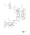
- Fig. 1 is a schematic representation of a boiler system 1, as seen from the side thereof.
- the boiler system 1 comprises a boiler 2.
- a hot process gas often referred to as a flue gas stream
- the flue gas stream which contains polluting substances, including for example dust particles, sulphur dioxide, SO 2 , sulphur trioxide, SO 3 , nitrogen oxides, NO x , and carbon dioxide, CO 2 , leaves the boiler 2 via a gas duct 4.
- the gas duct 4 is operative for forwarding the flue gas stream to a conventional air pollution control system 6.
- the conventional air pollution control system 6 may include a dust collector 8, in the form of, e.g., an electrostatic precipitator, an example of which is described in US 4,502,872 . Furthermore, the conventional air pollution control system 6 comprises a duct 10 which is operative for forwarding the flue gas stream from the dust collector 8 to a sulphur dioxide capture device 12, sometimes referred to as a Flue Gas Desulfurization system (FGD), in the form of, for example, a wet scrubber. An example of a wet scrubber can be found in EP 0 162 536 A1 .
- the sulphur dioxide capture device 12 could also be a so-called dry system, an example of which is illustrated in WO 2004/026443 A1 , in which the flue gas stream is contacted with a moistened absorbent material.
- the conventional air pollution control system 6 could comprise further devices, such as a selective catalytic reduction reactor, e.g., of the type described in US 5,555,849 , for capturing nitrogen oxides from the flue gas stream, such further devices not being illustrated in Fig. 1 for reasons of clarity of illustration.
- a selective catalytic reduction reactor e.g., of the type described in US 5,555,849 , for capturing nitrogen oxides from the flue gas stream, such further devices not being illustrated in Fig. 1 for reasons of clarity of illustration.
- the flue gas stream which comprises very small amounts of most pollutants, but still most of the original concentration of carbon dioxide, oxygen and nitrogen, leaves the conventional air pollution control system 6 via a duct 14.
- the duct 14 is operative for forwarding the flue gas stream to a carbon dioxide capture system 16.
- the carbon dioxide capture system 16 comprises a CO 2 -absorber 18 in which the flue gas stream is brought into contact with an ammoniated solution.
- the ammoniated solution may also include a promoter to enhance the chemical reaction kinetics involved in the capture of CO 2 by the ammoniated solution.
- the promoter may include an amine (e.g. piperazine) or an enzyme (e.g., carbonic anhydrase or its analogs), which may be in the form of a solution or immobilized on a solid or semi-solid surface.
- a CO 2 -enriched solution pipe 20 is operative for forwarding, by means of a high pressure pump, not illustrated in Fig. 1 for reasons of clarity, a CO 2 -enriched ammoniated solution from the CO 2 -absorber 18 to a regenerator 22.
- Heat is provided to the regenerator 22 by a heating circuit 24 comprising a heater 26.
- the high pressure and high temperature in the regenerator 22 causes the release of high-pressure gaseous CO 2 , which is forwarded, via a duct 28, to an optional CO 2 compression unit 30 in which the CO 2 is further compressed, and optionally further cleaned, to obtain a stream of cleaned compressed CO 2 that may be sent for CO 2 sequestration via duct 32.
- a CO 2 -lean ammoniated solution pipe 34 is operative for returning CO 2 -lean ammoniated solution from the regenerator 22 to the CO 2 -absorber 18.
- a duct 36 is operative for forwarding a cleaned flue gas stream, having a low concentration of carbon dioxide, from the CO 2 -absorber 18 to a water wash vessel 38, which is optional and which is operative for capturing ammonia, NH 3 , from the flue gas stream that has been treated in the CO 2 -absorber 18.
- a stream of cold water containing low concentration of ammoniated solution is supplied via pipe 40, is cooled in a heat exchanger 42 and is supplied to the water wash vessel 38.
- a duct 44 is operative for forwarding a flue gas stream that has been further cleaned in the water wash vessel 38, to a stack 46 which releases the further cleaned flue gas stream to the atmosphere.
- a portion of the cold water circulating in water wash vessel 38 and having captured ammonia may be transported, via pipe 47, to the CO 2 -absorber 18.
- Fig. 2 is a schematic side view of the CO 2 -absorber 18.
- the absorber 18 comprises a single vessel having the shape of a single tower 48.
- the tower 48 is provided with an inlet 50 located near the bottom of tower 48 and arranged for receiving the flue gas stream entering via duct 14.
- Flue gas stream FG may pass vertically upwards through tower 48 and leave tower 48 via an outlet 52 located near the top of tower 48. Flue gas stream FG leaving tower 48 via outlet 52 is forwarded further, via duct 36, to optional water wash vessel 38 and stack 46, as illustrated in Fig. 1 .
- the absorber 18 comprises a first, lower, absorption stage 54, and a second, upper, absorption stage 56.
- the first absorption stage 54 comprises a first contacting means comprising a mass transfer device 58, which may, for example, comprise a random or structured packing.
- a structured packing material is MellapakTM available from Sulzer Chemtech AG, Winterthur, CH.
- An example of a random packing material is PallTM rings available from Raschig GmbH, Ludwigshafen, DE.
- the first contacting means of the first absorption stage 54 further comprises a liquid distributor 60 which is arranged for distributing an ammoniated solution over the mass transfer device 58.
- the liquid distributor 60 may comprise nozzles or openings through which the ammoniated solution may be distributed over the mass transfer device 58.
- the second absorption stage 56 comprises a second contacting means comprising a mass transfer device 62, which may be of a similar or different type as mass transfer device 58, and a liquid distributor 64 which may be of a similar or different type as liquid distributor 60. Liquid distributor 64 is adapted for distributing solution over the mass transfer device 62.
- a collecting device in the form of a tank 66 is arranged at the bottom of the tower 48 for collecting CO 2 -enriched ammoniated solution to form a collected CO 2 -enriched ammoniated solution.
- a pipe 68 is connected to the tank 66 for transporting a stream of CO 2 -enriched solution from the tank 66 to a splitting point 70.
- the flow of collected CO 2 -enriched solution is split into a first portion being a first CO 2 -enriched solution stream which is forwarded, via CO 2 -enriched solution pipe 20 and a high-pressure pump 72, to the regenerator 22 illustrated in Fig.
- a central portion 75 of the tower 48 forms a transfer device which allows the direct transfer of partly cleaned flue gas stream FG coming from the first absorption stage 54 to the second absorption stage 56, and allows transfer of recirculated CO 2 -enriched solution from the second absorption stage 56 to the first absorption stage 54.
- the recirculated CO 2 -enriched solution flows vertically downwards, by gravity, from the second absorption stage 56 to the first absorption stage 54.
- a pump is not needed for transferring the recirculated CO 2 -enriched solution from second stage 56 to first stage 54.
- a recirculation pump 76 is arranged on the recirculation pipe 74 for transporting the second stream from the splitting point 70 to the second stage 56.
- a water cooler 78 is arranged on the recirculation pipe 74 for cooling the recirculated CO 2 -enriched solution before allowing the recirculated CO 2 -enriched solution to enter the liquid distributor 64 of the second stage 56.
- the pipe 20 and the recirculation pipe 74 could be fluidly connected directly to the tank 66.
- the second stream of collected CO 2 -enriched solution forwarded, as a recirculated CO 2 -enriched solution, via recirculation pipe 74 to the second stage 56 would comprise 30-70 % by weight of the total amount of collected CO 2 -enriched solution being transported from tank 66.
- the first stream of collected CO 2 -enriched solution forwarded via pipe 20 to the regenerator 22 illustrated in Fig. 1 comprises the remaining 70-30 % by weight of the total amount of collected CO 2 -enriched solution being transported from tank 66.
- CO 2 -lean solution is supplied from the regenerator 22 illustrated in Fig. 1 to the liquid distributor 60 of the first, lower, absorption stage 54 of the absorber 18 via the CO 2 -lean solution pipe 34.
- the CO 2 -lean solution supplied via pipe 34 could be heat-exchanged in a heat exchanger 80 with the CO 2 -enriched solution of pipe 20 before entering liquid distributor 60.
- a further heat exchanger 82 could be arranged in the pipe 34 for further cooling the CO 2 -lean solution before the latter enters the liquid distributor 60.
- the cooling medium of the heat exchanger 82 is preferably water, for example from a cooling tower, since the cooling requirement for the CO 2 -lean solution is moderate.
- the amount of the first portion of the collected CO 2 -enriched ammoniated solution, forwarded to the regenerator 22 via pipe 20, in relation to the amount of the second portion of the collected CO 2 -enriched ammoniated solution, forwarded to the second absorption stage 56 via pipe 74 can be controlled.
- a first control valve 84 may be arranged in the pipe 20
- a second control valve 86 may be arranged in the pipe 74.
- the absorber 18 may be provided with a third, uppermost, absorption stage 90.
- the third stage 90 is an ammonia polishing stage having the purpose of further reducing the load of ammonia on the water wash vessel 38 illustrated in Fig. 1 .
- the third absorption stage 90 comprises a third contacting means comprising a mass transfer device 92, which may be of a similar or different type as mass transfer device 58, and a liquid distributor 94 which may be of a similar or different type as liquid distributor 60. Liquid distributor 94 is adapted for distributing solution over the mass transfer device 92.
- a "polishing portion" of the recirculated CO 2 -enriched ammoniated solution supplied from pump 76 via recirculation pipe 74 may, in this further embodiment, be branched off to a polishing stage recirculation pipe 96.
- the remainder of the recirculated CO 2 -enriched ammoniated solution, which remainder may be referred to as a "CO 2 absorbing portion" of the recirculated CO 2 -enriched ammoniated solution is, in this further embodiment, transported via a further recirculation pipe 98, to the second stage 56 for being used in the absorption of CO 2 and ammonia in the second absorption stage 56 in accordance with the principles described hereinbefore.
- a valve 100 has been arranged on the polishing stage recirculation pipe 96, and a valve 102 has been arranged on the further recirculation pipe 98.
- a suitable amount of recirculated CO 2 -enriched ammoniated solution can be supplied to each of the stages 56, 90.
- a refrigerated cooler 104 may be arranged in the polishing stage recirculation pipe 96.
- the refrigerated cooler 104 may be connected to a refrigeration unit, not shown, which supplies a low temperature cooling medium, such as a water-glycol mixture, an organic cooling media, or ammonia, having a temperature of typically 0-8°C, to the refrigerated cooler 104.
- the refrigerated cooler 104 may typically be arranged for cooling the polishing portion of the recirculated CO 2 -enriched ammoniated solution transported in the polishing stage recirculation pipe 96 to a polishing temperature of about 0-10°C, preferably 3-7°C.
- the polishing temperature of about 0-10°C i.e., the temperature of the polishing portion of the recirculated CO 2 -enriched ammoniated solution supplied to the third stage 90, is lower than the absorbing temperature of typically 20-25°C of the CO 2 absorbing portion of the recirculated CO 2 -enriched ammoniated solution supplied to the second stage 56.
- the low polishing temperature of the polishing portion of the recirculated CO 2 -enriched ammoniated solution supplied to the third stage 90 is very efficient for polishing the cleaned flue gas coming from the second stage 56 with respect to its concentration of ammonia.
- a further cleaned flue gas with a very low concentration of ammonia leaves the absorber 18 via the outlet 52 and is forwarded, via duct 36, to optional water wash vessel 38.
- a portion of the recirculated CO 2 -enriched ammoniated solution pumped in pipe 74 by pump 76 is directed, via a first by-pass pipe 106, to the CO 2 -lean ammoniated solution pipe 34 and further to the first absorption stage 54.
- 0-50 % of the total flow of recirculated CO 2 -enriched ammoniated solution pumped by pump 76 would be directed to the first stage 54 for the purpose of reducing the concentration of ammonia of the partially cleaned flue gas, and the remaining 50-100 % would be pumped to the second stage 56, and third stage 90, if present.
- a portion of the CO 2 -lean ammoniated solution forwarded from the regenerator 22 via the pipe 34 may be forwarded, via a second by-pass pipe 108, to the recirculation pipe 74, 98 and further to the second absorption stage 56.
- An advantage of forwarding a portion of the CO 2 -lean ammoniated solution to the second stage 56 is that in some cases it is desired to increase the CO 2 absorption capacity of the second absorption stage 56.
- a portion of the CO 2 -lean ammoniated solution forwarded from the regenerator 22 via the pipe 34 may be forwarded, via a third by-pass pipe 110, to the polishing stage recirculation pipe 96, optionally via the refrigerated cooler 104, and further to the third absorption stage 90.
- An advantage of forwarding a portion of the CO 2 -lean ammoniated solution to the third stage 90 is that in some cases it is desired to reduce the risk of solid precipitation of ammonium bicarbonate and/or carbonate particles of the third stage 90.
- 0-5 % of the total flow of CO 2 -lean ammoniated solution of the pipe 34 would be forwarded to the third stage 90 for the purpose of reducing the risk of solid precipitation in the third stage 90, and the remaining amount of CO 2 -lean ammoniated solution would be forwarded to the first stage 54.
- a portion, typically 2-10% of the total flow of CO 2 -lean ammoniated solution transported to the absorber 18 from the regenerator 22 via the pipe 34 would be transported, via third by-pass pipe 110, to the third stage 90 in an intermittent manner.
- the CO 2 -lean ammoniated solution could be supplied to third stage 90, via third by-pass pipe 110, on regular intervals, for example during a period of 1-10 minutes every second hour, or when a formation of solid precipitation of ammonium bicarbonate particles in the third stage 90 has been detected, in order to dissolve formed ammonium bicarbonate particles.
- the function of the absorber 18 will now be described in more detail with reference to Fig. 2 , and a number of diagrams illustrating the operation.
- the diagrams relate to a computer simulation using AspenTM simulation tool of the performance of an absorber 18 having the first absorption stage 54, the second absorption stage 56, but not any third absorption stage 90.
- 100% of the recirculated CO 2 -enriched ammoniated solution pumped by pump 76 is transported to the second stage 56 and 100% of the CO 2 -lean ammoniated solution is transported to the first stage 54.
- Location AA refers to a location where the CO 2 -enriched solution forwarded via recirculation pipe 74 enters the absorber 18 and where the flue gas stream FG from which CO 2 has been captured leaves the absorber 18. Hence, location AA refers to conditions of "fresh recirculated CO 2 -enriched solution" entering second stage 56 of absorber 18, and "cleaned flue gas stream” leaving second stage 56 of absorber 18.
- Location BB refers to a location where the recirculated CO 2 -enriched solution supplied via pipe 74 has passed through mass transfer device 62 of second stage 56 of absorber 18, and where partly cleaned flue gas stream FG is about to enter second stage 56.
- location BB refers to conditions of "partly spent recirculated CO 2 -enriched solution" leaving second stage 56 of absorber 18, and "partly cleaned flue gas stream" about to enter second stage 56 of absorber 18.
- Location CC refers to a location where the recirculated CO 2 -enriched solution having passed through mass transfer device 62 of second stage 56 of absorber 18 has been mixed with fresh CO 2 -lean solution entering via pipe 34, just prior to entering first stage 54 of absorber 18.
- the properties of the partly cleaned flue gas stream FG is substantially the same in location CC as in location BB.
- location CC refers to conditions of "mixture of partly spent recirculated CO 2 -enriched solution and fresh CO 2 -lean solution" about to enter first stage 54 of absorber 18, and "partly cleaned flue gas stream" leaving first stage 54 of absorber 18.
- Location DD refers to a location where the mixture of the recirculated CO 2 -enriched solution and the CO 2 -lean solution has passed through mass transfer device 58 of first stage 54 of absorber 18, and where CO 2 -rich flue gas stream FG is about to enter first stage 54.
- location DD refers to conditions of "mixture of spent CO 2 -enriched solution and spent CO 2 -lean solution" leaving first stage 54 of absorber 18, and "CO 2 -rich flue gas stream” about to enter first stage 54 of absorber 18.
- the conditions of the mixture of the spent CO 2 -enriched solution and spent CO 2 -lean solution in location DD is substantially the same as the conditions of the solution collected in tank 66, and forwarded via pipes 68, 20 and 74.
- Fig. 3 illustrates the relation between the carbon dioxide, CO 2 , and the ammonia, NH 3 , in the ammoniated solution in various positions of the absorber 18 illustrated in Fig. 2 , as obtained from a computer simulation of the performance of the absorber 18.
- 50 % by weight of the amount of solution collected in tank 66 was recirculated to second stage 56 via pipe 74, and 50% by weight of the amount of solution collected in tank 66 was forwarded to regenerator 22 for being regenerated.
- the amount of CO 2 -lean solution entering the absorber 18 via pipe 34 was equal to the amount of CO 2 -enriched solution leaving the absorber 18 via pipe 20, except for the fact that a portion of the CO 2 content of the CO 2 -enriched solution was released in the regenerator 22.
- ammonia slipping out of the absorber 18 was compensated for by adding a similar amount to the CO 2 -enriched solution, such that the concentration of ammonia was constant over time.
- a high R-value is beneficial for the capture of CO 2 from the flue gas stream.
- a high R-value also causes an increased vapour pressure of NH 3 , which potentially increases slip of ammonia from absorber.
- a high temperature is beneficial for the kinetics of the capture of CO 2 .
- a high temperature also increases the vapour pressure of NH 3 .
- the R-value of the recirculated CO 2 -enriched solution entering absorber 18 would be in the range of 1.75 to 2.00.
- the liquid to gas ratio i.e. the amount of recirculated CO 2 -enriched solution passing through mass transfer device 62 of the second stage 56 in relation to the amount of flue gas passing through mass transfer device 62 of the second stage 56, also referred to as L/G, is, in the simulation, about 6 kg of recirculated CO 2 -enriched ammoniated solution per kg of flue gas, as viewed in location AA.
- the L/G of the second stage 56, as viewed in location AA is 3 to 10, and more preferably 4 to 8, kg solution / kg flue gas.
- the L/G is not absolutely constant through the mass transfer device 62 since capture of CO 2 and NH 3 in the solution causes a transfer of mass from the flue gas stream to the solution.
- the concentration of ammonia, NH 3 , of the CO 2 -lean ammoniated solution and of the recirculated CO 2 -enriched ammoniated solution would be in the range of 4-12 mole NH 3 per litre of solution.
- the corresponding concentration of carbon dioxide, CO 2 can be calculated from the respective R-value of the solution in question.
- the CO 2 -lean solution supplied via pipe 34 has an R-value of about 3.0. Typically, the R-value of the CO 2 -lean solution in pipe 34 would be in the range of 2.5 to 4.50.
- the R-value of the mixture in location CC would be in the range of 1.90 to 2.40.
- Such a high R-value means that a very efficient capture of CO2 in first stage 54 can be obtained.
- the R-value of the ammoniated solution is within the range 1.70 to 2.00 in location DD.
- Solution with an R-value of about 1.88 is, hence, collected in tank 66, and is partly returned to second stage 56, via pipe 74, and partly forwarded to the regenerator 22, illustrated in Fig. 1 , via pipe 20.
- the liquid to gas ratio, L/G i.e. the amount of the mixture of the recirculated CO 2 -enriched solution and the CO 2 -lean solution passing through mass transfer device 58 of the first stage 54 in relation to the amount of flue gas passing through mass transfer device 58 of the first stage 54 is, in the simulation, about 12 kg of the mixture of recirculated CO 2 -enriched solution and CO 2 -lean solution per kg of flue gas, as viewed in location CC.
- the L/G of the first stage 54, as viewed in location CC is 5 to 16, more preferably 7 to 12, and most preferably 8 to 10 kg solution / kg flue gas. It will be appreciated that the L/G is not absolutely constant through the mass transfer device 58 since capture of CO 2 and NH 3 in the solution causes a transfer of mass from the flue gas stream to the solution.
- the L/G is controlled by controlling the valves 84, 86. For example, increasing the degree of opening of valve 84 and reducing the degree of opening of valve 86 reduces the L/G in the second absorption stage 56.
- Fig. 4 illustrates the temperature of the ammoniated solution in various positions of the absorber 18 illustrated in Fig. 2 , as obtained from the simulation of the performance of the absorber 18.
- the temperature of the ammoniated solution in a specific location is almost the same as the temperature of the flue gas stream in that same location.
- the recirculated CO 2 -enriched solution enters absorber 18, location AA, at a temperature of about 10°C.
- the temperature of the recirculated CO 2 -enriched solution entering absorber 18 would be in the range of 8-30°C.
- a third absorption stage 90 is included a rather high temperature, preferably 20-25°C, would be suitable for the recirculated CO 2 -enriched solution entering absorber 18 via pipe 98.
- the computer simulation illustrated in Figs. 3-5 was made with only the first and second stages 54, 56, and in such a case a lower temperature, such as 10°C, is suitable to achieve a low ammonia slip.
- Heat exchanger 78 illustrated in Fig. 2 , utilizing, for example, cooling water from a cooling tower for the cooling, is utilized for cooling the CO 2 -enriched solution in pipe 74 to such desired temperature.
- the temperature gradually increases to about 15°C, which is the temperature in location BB.
- a dashed line referred to as "solidification” has been introduced to illustrate that temperature below which ammonium bicarbonate particles may start to precipitate from the ammoniated solution, given the R-values illustrated in Fig. 3 .
- the solidification temperature is about 4°C.
- the temperature is above the solidification temperature, and no, or almost no, precipitation of ammonium bicarbonate particles occurs.
- a temperature of 10°C in location AA results in a low vapour pressure of ammonia, and a low ammonia slip, as will be demonstrated hereinafter.
- the CO 2 -lean solution supplied via pipe 34 has a temperature, upon entering the first stage 54 of the absorber 18, i.e., downstream of the further heat exchanger 82, of about 30°C.
- the temperature of the CO 2 -lean solution entering absorber 18 would be in the range of 20-40°C.
- location CC the CO 2 -lean solution is mixed with the partly spent recirculated CO 2 -enriched solution having passed through second stage 56.
- the temperature, in location CC becomes about 25°.
- the temperature of the mixture of the CO 2 -lean solution and the partly spent recirculated CO 2 -enriched solution in location CC would be in the range of 20-30°C.
- Such a relatively high temperature has been found to be positive to the kinetics of the CO 2 absorption, and means that a very efficient capture of CO 2 in first stage 54 can be obtained.
- the temperature gradually increases to about 29°C, which is the temperature in location DD. Solution with temperature of about 29°C is, hence, collected in tank 66.
- Fig. 5 is a diagram illustrating the molar fractions of carbon dioxide, CO 2 , and ammonia, NH 3 , of the flue gas stream FG in various positions of the CO 2 -absorber 18 of Fig. 2 .
- the CO 2 -rich flue gas stream FG entering absorber 18 via inlet 50 contains a large amount of CO 2 .
- NH 3 Almost immediately upon entering into tower 48 ammonia, NH 3 , will evaporate from the ammoniated solution, due to the equilibrium conditions at the R-value and temperature demonstrated hereinabove, and mix with the flue gas stream, FG.
- the flue gas stream FG will contain CO 2 in a molar fraction of about 0.15, and NH 3 in a molar fraction of about 0.03.
- the solution While passing through the mass transfer device 58 of the first stage 54 the solution will efficiently capture CO 2 .
- the partly cleaned flue gas stream FG will contain CO 2 in a molar fraction of about 0.055, and NH 3 in a molar fraction of about 0.035.
- the partly cleaned flue gas stream FG will contain CO 2 in a molar fraction of about 0.055, and NH 3 in a molar fraction of about 0.01.
- the flue gas stream FG While passing through the mass transfer device 62 of the second stage 56 the solution will capture CO 2 .
- the flue gas stream FG will contain CO 2 in a molar fraction of about 0.018, and NH 3 in a molar fraction of about 0.01.
- a low slip of ammonia, NH 3 is achieved, thanks to the conditions of the second stage 56.
- Very efficient capture of carbon dioxide, CO 2 is achieved in the first stage 54, and capture of carbon dioxide continues also in the second stage 56.
- the total L/G is about 12 kg solution / kg flue gas, which is typically in the range of 10-20% lower than the three absorber process illustrated in the prior art document WO 2009/055419 .
- electrical power supply may be reduced by about 10%, since the amount of solution pumped in the absorber is reduced.
- the absorber 18 is significantly simpler as regards construction and ancillary equipment, causing savings in capital and maintenance costs of at least 10%.
- the relatively high temperature of the solutions and the high R-values increases CO 2 capture efficiency and reduces the required volume of the mass transfer devices 58 and 62, thereby reducing the size and height of the tower 48. Still further, the amount of energy consumed in the refrigeration unit is reduced, since solutions circulating in the absorber 18 are typically cooled to, on average, an as high temperature as 20°C. If cooling water from a cooling tower is available, the energy consumption could be even further reduced.
- the absorber 18 comprises a single tower 48. It will be appreciated that the absorber could also comprise more than one tower.
- the second stage 56 could be arranged in a first tower which is separate from a second tower in which the first stage 54 is arranged, with flue gas stream and solution being transferred between the two towers.
- mass transfer devices 58, 62 may comprise structured or random packing. It will be appreciated that other mass transfer devices that provide efficient contact between solution and flue gas stream could also be arranged inside the tower.
- the absorber 18 comprises a first absorption stage 54 and a second absorption stage 56. It will be appreciated that the absorber 18 may also comprise further absorption stages. However, an absorber 18 comprising solely a first and a second absorption stage 54 and 56 is often very efficient with regard to capture of CO 2 and with regard to capital and operating costs.
- the L/G may, preferably, be 5 to 16 kg solution / kg flue gas in the first absorption stage 54, and 3 to 10 kg solution / kg flue gas in the second absorption stage 56. If the absorber 18 is provided with the optional third absorption stage 90, then the L/G of that third stage 90 would, preferably, be 0.5 to 2.5 kg solution / kg flue gas. The L/G of the second absorption stage 56 could remain unaffected, since in one embodiment the solution that has passed through the third stage 90, when present, would subsequently pass through the second stage 56 along with the solution supplied thereto.
- a system for capturing CO 2 from a flue gas stream comprises:
Landscapes
- Engineering & Computer Science (AREA)
- Chemical & Material Sciences (AREA)
- Analytical Chemistry (AREA)
- General Chemical & Material Sciences (AREA)
- Oil, Petroleum & Natural Gas (AREA)
- Chemical Kinetics & Catalysis (AREA)
- Combustion & Propulsion (AREA)
- Mechanical Engineering (AREA)
- General Engineering & Computer Science (AREA)
- Health & Medical Sciences (AREA)
- Biomedical Technology (AREA)
- Environmental & Geological Engineering (AREA)
- Treating Waste Gases (AREA)
- Gas Separation By Absorption (AREA)
Abstract
- a CO2 absorber (18) comprising first and second absorption stages (54, 56),
- first contacting means (58, 60) for contacting, in the first stage (54), the flue gas stream (FG) with a mixture of CO2-lean ammoniated solution and recirculated CO2-enriched ammoniated solution,
- second contacting means (62, 64) for contacting, in the second stage (56), partly cleaned flue gas stream with the recirculated CO2-enriched solution,
- a device (66) for collecting the mixture of CO2-lean solution and recirculated CO2-enriched solution,
- a pipe (20) for passing a first portion of the collected CO2-enriched solution for regeneration,
- a CO2-lean solution pipe (34) for passing the CO2-lean solution from regeneration to the first stage (54), and
- a recirculation pipe (74) for passing a second portion of the collected CO2-enriched solution to the second stage (56).
Description
- The present invention relates to a method of capturing CO2 from a flue gas stream in a CO2-absorber.
- The present invention further relates to system for capturing CO2 from a flue gas stream.
- In the combustion of a fuel, such as coal, oil, peat, waste, natural gas, etc., in a combustion plant, such as a power plant, a hot process gas is generated, such process gas containing, among other components, carbon dioxide, CO2. The negative environmental effects of releasing carbon dioxide to the atmosphere have been widely recognized, and have resulted in the development of processes adapted for capturing carbon dioxide from the hot process gas generated in the combustion of the above mentioned fuels. One such system and process has previously been disclosed and is directed to a Chilled Ammonia based system and method for capture of CO2 from a post-combustion flue gas stream using an ammoniated solution and/or slurry for capturing CO2 from a flue gas stream.
WO 2009/055419 discloses a process and system using three absorbers to improve efficiency of the CO2 capture process. The system disclosed inWO 2009/055419 is, however, complicated from a technical point of view, and has a high operating cost. - The above drawbacks and deficiencies of the prior art are overcome or alleviated by means of a method of capturing CO2 from a flue gas stream in a CO2-absorber, the method comprising:
- contacting, in a first absorption stage of the CO2-absorber, the flue gas stream with a mixture of CO2-lean ammoniated solution and recirculated CO2-enriched ammoniated solution to form a partly cleaned flue gas stream,
- contacting, in a second absorption stage of the CO2-absorber, the partly cleaned flue gas stream with the recirculated CO2-enriched ammoniated solution to form a cleaned flue gas stream,
- forming a collected CO2-enriched ammoniated solution by collecting the mixture of CO2-lean ammoniated solution and recirculated CO2-enriched ammoniated solution after having passed through the first absorption stage,
- passing a first portion of the collected CO2-enriched ammoniated solution for regeneration for removing CO2 from the first portion of the collected CO2-enriched ammoniated solution to form the CO2-lean ammoniated solution, and
- utilizing a second portion of the collected CO2-enriched ammoniated solution to form the recirculated CO2-enriched ammoniated solution.
- An advantage of this method is that carbon dioxide can be efficiently captured, without an undue slip of ammonia, with lower operating cost and capital costs compared to the prior art.
- According to one embodiment the method further comprises forwarding the recirculated CO2-enriched ammoniated solution first through the second absorption stage, and then through the first absorption stage. An advantage of this embodiment is that the recirculated CO2-enriched ammoniated solution acts as a barrier to gaseous ammonia and serves to collect not only carbon dioxide, but also ammonia from the flue gas, before the flue gas is forwarded from the second stage to a water wash vessel or an ammonia polishing stage, as the case may be.
- According to one embodiment the method further comprises forwarding the CO2-lean ammoniated solution through the first absorption stage without forwarding the CO2-lean ammoniated solution through the second absorption stage. An advantage of this embodiment is an improved mass transfer of CO2 from the gas phase to the liquid phase by achieving a concentration profile with regard to CO2 in the ammoniated solution which varies in an optimum manner along the CO2-absorber.
- According to one embodiment the recirculated CO2-enriched ammoniated solution and the CO2-lean ammoniated solution are kept at a temperature, while passing through the first and second absorption stages, which is above a temperature at which ammonium bicarbonate particles may start to precipitate from the respective ammoniated solution. An advantage of this embodiment is that the absorber operates entirely in solution mode, with no, or almost no, formation of solid carbonate particles. This reduces risks of clogging in the absorber and makes absorber operation more robust. It is also possible to reduce the liquid to gas ratio, L/G, in the absorber since operating with solid formation in accordance with the prior art requires high liquid to gas ratios to reduce risks of solids accumulating in unwanted locations inside the absorber.
- According to one embodiment the partly cleaned flue gas stream is passed vertically upwards from the first absorption stage to the second absorption stage, and wherein the recirculated CO2-enriched ammoniated solution is passed vertically downwards from the second absorption stage to the first absorption stage. An advantage of this embodiment is that gas distribution of the partly cleaned flue gas stream entering vertically upwards into the second absorption stage becomes very even and efficient, and so does the liquid distribution of the recirculated CO2-enriched ammoniated solution entering vertically downwards into the first absorption stage.
- According to one embodiment the method further comprises contacting, in a third absorption stage, being an ammonia polishing stage, of the CO2-absorber, the cleaned flue gas stream coming from the second absorption stage with a polishing portion of the recirculated CO2-enriched ammoniated solution to form a further cleaned flue gas stream, the polishing portion of the recirculated CO2-enriched ammoniated solution being cooled, prior to being supplied to the third stage, to a polishing temperature which is lower than an absorbing temperature of the absorbing portion of the recirculated CO2-enriched ammoniated solution supplied to the second stage. An advantage of this embodiment is that a very low equilibrium pressure of ammonia, beneficial for low slip of ammonia, is achieved in the third absorption stage. Still further, only a small amount of the recirculated CO2-enriched ammoniated solution needs to be cooled to the low temperature for ammonia capture in the third absorption stage, which reduces the need for installed cooling power, and in particular the need for installed refrigeration unit capacity.
- According to one embodiment the method further comprises mixing the polishing portion of the recirculated CO2-enriched ammoniated solution, after having passed through the third absorption stage, with the absorbing portion of the recirculated CO2-enriched ammoniated solution to form the recirculated CO2-enriched ammoniated solution passing through the second absorption stage. An advantage of this embodiment is that the polishing portion of the recirculated CO2-enriched ammoniated solution is utilized in an efficient manner for absorbing ammonia in both the third and second absorption stages in a counter-current mode in relation to the flue gas flow.
- According to one embodiment the R-value, being the molar concentration of NH3 divided by the molar concentration of CO2, of the recirculated CO2-enriched ammoniated solution supplied to the second absorption stage is within the range of 1.75 to 2.00. An advantage of this embodiment is that efficient capture of carbon dioxide is achieved, still at a low slip of ammonia, and with little, or no, formation of solid ammonium bicarbonate. More preferably, the R-value of the recirculated CO2-enriched ammoniated solution supplied to the second absorption stage may be within the range of 1.81 to 1.96.
- According to one embodiment, the temperature of the recirculated CO2-enriched ammoniated solution supplied to the second absorption stage is controlled to be within the range of 8-30°C, more preferably 20-25°C. An advantage of this temperature range is that efficient capture of carbon dioxide, low slip of ammonia, and little, or no, formation of solid ammonium bicarbonate is achieved.
- According to one embodiment, the R-value of the ammoniated solution is within the range of 1.70 to 2.80 throughout the entire first absorption stage. An advantage of this embodiment is that very efficient capture of carbon dioxide is achieved, still with no, or only little, formation of solid ammonium bicarbonate.
- According to one embodiment, the R-value of the recirculated CO2-enriched ammoniated solution entering to the second absorption stage is lower than the R-value of the mixture of recirculated CO2-enriched ammoniated solution and the CO2-lean ammoniated solution entering the first absorption stage. An advantage of this embodiment is that efficient capture of carbon dioxide is achieved in the first absorption stage, and a very low slip of ammonia is achieved from the second absorption stage.
- According to one embodiment, the temperature of the mixture of recirculated CO2-enriched ammoniated solution and CO2-lean ammoniated solution entering the first absorption stage is higher than the temperature of the recirculated CO2-enriched ammoniated solution entering the second absorption stage. An advantage of this embodiment is that kinetics beneficial for efficient absorption of CO2 are improved in the mass transfer device of the first stage, which significantly reduces the need for height of the mass transfer device packing of the first absorption stage.
- According to one embodiment, the liquid to gas ratio, L/G, on a mass basis is 5 to 16, more preferably 7 to 12, and most preferably 8 to 10 kg solution / kg flue gas in the first absorption stage. The L/G is 3 to 10, and more preferably 4 to 8, kg solution / kg flue gas in the second absorption stage. Such liquid to gas ratios have been found to result in efficient capture of carbon dioxide, with low energy consumption. Additionally, the relatively low L/G increases the temperature inside the absorber, in particular in the first absorption stage, since the exothermic absorption of CO2 has to heat a smaller amount of solution. An increased temperature in the absorber is beneficial for the kinetics of the capture of CO2. Furthermore, the relatively low L/G reduces back-mixing, i.e., occasional entrainment upwards of solution, which further increases the CO2 capture due to a more stable counter-current flow between solution and gas.
- According to one embodiment the first portion of the collected CO2-enriched ammoniated solution comprises 30 to 70 % by weight of the collected CO2-enriched ammoniated solution, and wherein the second portion of the collected CO2-enriched ammoniated solution comprises 70 to 30 % by weight of the collected CO2-enriched ammoniated solution. An advantage of this embodiment is that efficient balance between recirculation and regeneration of the collected CO2-enriched ammoniated solution is achieved, resulting in efficient operation of the first and second absorption stages, and low total liquid to gas ratio.
- According to one embodiment 4-30% of the total flow of the CO2-lean ammoniated solution forwarded to the CO2-absorber is forwarded to the second absorption stage for contacting the partly cleaned flue gas stream. An advantage of this embodiment is that an enhanced removal of CO2 in the second absorption stage may be achieved.
- The above mentioned drawbacks and deficiencies of the prior art are also overcome or alleviated by means of a system for capturing CO2 from a flue gas stream which comprises:
- a CO2 absorber comprising a first absorption stage and a second absorption stage,
- an inlet for forwarding a flue gas stream to the first absorption stage,
- first contacting means for contacting, in the first absorption stage, the flue gas stream with a mixture of CO2-lean ammoniated solution and recirculated CO2-enriched ammoniated solution to form a partly cleaned flue gas stream,
- a transfer device for transferring the partly cleaned flue gas stream from the first absorption stage to the second absorption stage,
- second contacting means for contacting, in the second absorption stage, the partly cleaned flue gas stream with the recirculated CO2-enriched ammoniated solution to form a cleaned flue gas stream,
- an outlet for cleaned flue gas stream forwarded from the second absorption stage,
- a device for collecting the mixture of CO2-lean ammoniated solution and recirculated CO2-enriched ammoniated solution after having passed through the first absorption stage to form a collected CO2-enriched ammoniated solution,
- a CO2-enriched solution pipe for passing a first portion of the collected CO2-enriched ammoniated solution for regeneration for removing CO2 from the first portion of the collected CO2-enriched ammoniated solution to form the CO2-lean ammoniated solution,
- a CO2-lean solution pipe for passing the CO2-lean ammoniated solution from regeneration to the first absorption stage, and
- a recirculation pipe for passing a second portion of the collected CO2-enriched ammoniated solution to the second absorption stage to form the recirculated CO2-enriched ammoniated solution.
- An advantage of this system is that it is robust and has lower operating and capital costs compared to the prior art systems.
- According to one embodiment, the system comprises a heat exchanger arranged on the recirculation pipe for cooling the recirculated CO2-enriched ammoniated solution prior to being supplied to the second absorption stage. An advantage of this embodiment is that cooling to a suitable temperature for the second absorption stage can be achieved efficiently. Often a relatively simple water cooled heat exchanger is sufficient. At the relatively high temperature level of the second absorption stage much of the heat that needs to be cooled away can be rejected using cooling water, for example from a cooling tower, thus reducing the heat load on a refrigeration unit involving, for example, compression stages and organic cooling media. If cooling water is available at low temperatures, such as 5-10°C, the need for refrigeration can be eliminated so that the capacity of the refrigeration unit is significantly reduced.
- According to one embodiment, the absorber comprises a single tower housing the first and the second contacting means, with the second contacting means being located vertically above the first contacting means inside the tower. An advantage of this embodiment using a single tower which is common to the first and second contacting means is that a simple absorber design can be utilized. Furthermore, the transfer of partly cleaned flue gas and recirculated CO2-enriched ammoniated solution between the first and second absorption stages can be made efficient, in a "plug flow" manner and in a way which ensures good distribution of flue gas and solution within packing material of the respective stage. Optionally, when a third absorption stage is included in the absorber for polishing ammonia, a third contacting means of the third absorption stage may be arranged within the single tower housing together with the first and the second contacting means. In such case the third contacting means would be located vertically above the second contacting means.
- Further objects and features of the present invention will be apparent from the following detailed description and claims.
- The invention is described in more detail below with reference to the appended drawings in which:
-
Fig. 1 is a schematic side view of a boiler system. -
Fig. 2 is a schematic side view of a CO2-absorber. -
Fig. 3 is a diagram illustrating the composition of ammoniated solution in various positions of the CO2-absorber ofFig. 2 . -
Fig. 4 is a diagram illustrating the temperature of ammoniated solution in various positions of the CO2-absorber ofFig. 2 . -
Fig. 5 is a diagram illustrating the molar fractions of carbon dioxide and ammonia of the flue gas stream in various positions of the CO2-absorber ofFig. 2 . -
Fig. 1 is a schematic representation of aboiler system 1, as seen from the side thereof. Theboiler system 1 comprises aboiler 2. During the combustion of a fuel, such as coal or oil, a hot process gas, often referred to as a flue gas stream, is generated in theboiler 2. The flue gas stream, which contains polluting substances, including for example dust particles, sulphur dioxide, SO2, sulphur trioxide, SO3, nitrogen oxides, NOx, and carbon dioxide, CO2, leaves theboiler 2 via a gas duct 4. The gas duct 4 is operative for forwarding the flue gas stream to a conventional airpollution control system 6. The conventional airpollution control system 6 may include adust collector 8, in the form of, e.g., an electrostatic precipitator, an example of which is described inUS 4,502,872 . Furthermore, the conventional airpollution control system 6 comprises aduct 10 which is operative for forwarding the flue gas stream from thedust collector 8 to a sulphurdioxide capture device 12, sometimes referred to as a Flue Gas Desulfurization system (FGD), in the form of, for example, a wet scrubber. An example of a wet scrubber can be found inEP 0 162 536 A1dioxide capture device 12 could also be a so-called dry system, an example of which is illustrated inWO 2004/026443 A1 , in which the flue gas stream is contacted with a moistened absorbent material. - The conventional air
pollution control system 6 could comprise further devices, such as a selective catalytic reduction reactor, e.g., of the type described inUS 5,555,849 , for capturing nitrogen oxides from the flue gas stream, such further devices not being illustrated inFig. 1 for reasons of clarity of illustration. - The flue gas stream, which comprises very small amounts of most pollutants, but still most of the original concentration of carbon dioxide, oxygen and nitrogen, leaves the conventional air
pollution control system 6 via aduct 14. Theduct 14 is operative for forwarding the flue gas stream to a carbondioxide capture system 16. The carbondioxide capture system 16 comprises a CO2-absorber 18 in which the flue gas stream is brought into contact with an ammoniated solution. The ammoniated solution may also include a promoter to enhance the chemical reaction kinetics involved in the capture of CO2 by the ammoniated solution. For example, the promoter may include an amine (e.g. piperazine) or an enzyme (e.g., carbonic anhydrase or its analogs), which may be in the form of a solution or immobilized on a solid or semi-solid surface. - A CO2-enriched solution pipe 20 is operative for forwarding, by means of a high pressure pump, not illustrated in
Fig. 1 for reasons of clarity, a CO2-enriched ammoniated solution from the CO2-absorber 18 to aregenerator 22. Heat is provided to theregenerator 22 by aheating circuit 24 comprising aheater 26. The high pressure and high temperature in theregenerator 22 causes the release of high-pressure gaseous CO2, which is forwarded, via aduct 28, to an optional CO2 compression unit 30 in which the CO2 is further compressed, and optionally further cleaned, to obtain a stream of cleaned compressed CO2 that may be sent for CO2 sequestration viaduct 32. A CO2-leanammoniated solution pipe 34 is operative for returning CO2-lean ammoniated solution from theregenerator 22 to the CO2-absorber 18. - A
duct 36 is operative for forwarding a cleaned flue gas stream, having a low concentration of carbon dioxide, from the CO2-absorber 18 to awater wash vessel 38, which is optional and which is operative for capturing ammonia, NH3, from the flue gas stream that has been treated in the CO2-absorber 18. A stream of cold water containing low concentration of ammoniated solution is supplied viapipe 40, is cooled in aheat exchanger 42 and is supplied to thewater wash vessel 38. Aduct 44 is operative for forwarding a flue gas stream that has been further cleaned in thewater wash vessel 38, to astack 46 which releases the further cleaned flue gas stream to the atmosphere. Optionally, a portion of the cold water circulating in water washvessel 38 and having captured ammonia may be transported, viapipe 47, to the CO2-absorber 18. -
Fig. 2 is a schematic side view of the CO2-absorber 18. Theabsorber 18 comprises a single vessel having the shape of asingle tower 48. Thetower 48 is provided with aninlet 50 located near the bottom oftower 48 and arranged for receiving the flue gas stream entering viaduct 14. Flue gas stream FG may pass vertically upwards throughtower 48 and leavetower 48 via anoutlet 52 located near the top oftower 48. Flue gas streamFG leaving tower 48 viaoutlet 52 is forwarded further, viaduct 36, to optionalwater wash vessel 38 andstack 46, as illustrated inFig. 1 . - As is illustrated in
Fig. 2 , theabsorber 18 comprises a first, lower,absorption stage 54, and a second, upper,absorption stage 56. Thefirst absorption stage 54 comprises a first contacting means comprising amass transfer device 58, which may, for example, comprise a random or structured packing. An example of a structured packing material is Mellapak™ available from Sulzer Chemtech AG, Winterthur, CH. An example of a random packing material is Pall™ rings available from Raschig GmbH, Ludwigshafen, DE. The first contacting means of thefirst absorption stage 54 further comprises aliquid distributor 60 which is arranged for distributing an ammoniated solution over themass transfer device 58. Theliquid distributor 60 may comprise nozzles or openings through which the ammoniated solution may be distributed over themass transfer device 58. Thesecond absorption stage 56 comprises a second contacting means comprising amass transfer device 62, which may be of a similar or different type asmass transfer device 58, and aliquid distributor 64 which may be of a similar or different type asliquid distributor 60.Liquid distributor 64 is adapted for distributing solution over themass transfer device 62. - A collecting device in the form of a
tank 66 is arranged at the bottom of thetower 48 for collecting CO2-enriched ammoniated solution to form a collected CO2-enriched ammoniated solution. Apipe 68 is connected to thetank 66 for transporting a stream of CO2-enriched solution from thetank 66 to asplitting point 70. At thesplitting point 70 the flow of collected CO2-enriched solution is split into a first portion being a first CO2-enriched solution stream which is forwarded, via CO2-enriched solution pipe 20 and a high-pressure pump 72, to theregenerator 22 illustrated inFig. 1 for being regenerated in accordance with the previous description, and a second portion being a second CO2-enriched solution stream, forming a recirculated CO2-enriched ammoniated solution, forwarded via a recirculation pipe 74 to theliquid distributor 64 of thesecond stage 56. - A
central portion 75 of thetower 48 forms a transfer device which allows the direct transfer of partly cleaned flue gas stream FG coming from thefirst absorption stage 54 to thesecond absorption stage 56, and allows transfer of recirculated CO2-enriched solution from thesecond absorption stage 56 to thefirst absorption stage 54. The recirculated CO2-enriched solution flows vertically downwards, by gravity, from thesecond absorption stage 56 to thefirst absorption stage 54. A pump is not needed for transferring the recirculated CO2-enriched solution fromsecond stage 56 tofirst stage 54. Furthermore, it is not necessary to cool or heat the recirculated CO2-enriched solution when passing vertically downward fromsecond stage 56 tofirst stage 54. - A
recirculation pump 76 is arranged on the recirculation pipe 74 for transporting the second stream from thesplitting point 70 to thesecond stage 56. Awater cooler 78 is arranged on the recirculation pipe 74 for cooling the recirculated CO2-enriched solution before allowing the recirculated CO2-enriched solution to enter theliquid distributor 64 of thesecond stage 56. - As alternative to being connected to the
splitting point 70, thepipe 20 and the recirculation pipe 74 could be fluidly connected directly to thetank 66. - Typically, the second stream of collected CO2-enriched solution forwarded, as a recirculated CO2-enriched solution, via recirculation pipe 74 to the
second stage 56 would comprise 30-70 % by weight of the total amount of collected CO2-enriched solution being transported fromtank 66. The first stream of collected CO2-enriched solution forwarded viapipe 20 to theregenerator 22 illustrated inFig. 1 comprises the remaining 70-30 % by weight of the total amount of collected CO2-enriched solution being transported fromtank 66. - CO2-lean solution is supplied from the
regenerator 22 illustrated inFig. 1 to theliquid distributor 60 of the first, lower,absorption stage 54 of theabsorber 18 via the CO2-lean solution pipe 34. - Optionally, the CO2-lean solution supplied via
pipe 34 could be heat-exchanged in aheat exchanger 80 with the CO2-enriched solution ofpipe 20 before enteringliquid distributor 60. Furthermore, afurther heat exchanger 82 could be arranged in thepipe 34 for further cooling the CO2-lean solution before the latter enters theliquid distributor 60. The cooling medium of theheat exchanger 82 is preferably water, for example from a cooling tower, since the cooling requirement for the CO2-lean solution is moderate. - Both in the
first absorption stage 54 and in thesecond absorption stage 56, the contact between the flue gas stream and the respective solution occurs in a counter-current mode, with the flue gas stream FG flowing vertically upwards, and the respective solution flowing vertically downwards. - The amount of the first portion of the collected CO2-enriched ammoniated solution, forwarded to the
regenerator 22 viapipe 20, in relation to the amount of the second portion of the collected CO2-enriched ammoniated solution, forwarded to thesecond absorption stage 56 via pipe 74 can be controlled. To this end, afirst control valve 84 may be arranged in thepipe 20, and asecond control valve 86 may be arranged in the pipe 74. - According to a further embodiment, the
absorber 18 may be provided with a third, uppermost,absorption stage 90. Thethird stage 90 is an ammonia polishing stage having the purpose of further reducing the load of ammonia on thewater wash vessel 38 illustrated inFig. 1 . Thethird absorption stage 90 comprises a third contacting means comprising amass transfer device 92, which may be of a similar or different type asmass transfer device 58, and aliquid distributor 94 which may be of a similar or different type asliquid distributor 60.Liquid distributor 94 is adapted for distributing solution over themass transfer device 92. - A "polishing portion" of the recirculated CO2-enriched ammoniated solution supplied from
pump 76 via recirculation pipe 74 may, in this further embodiment, be branched off to a polishingstage recirculation pipe 96. The remainder of the recirculated CO2-enriched ammoniated solution, which remainder may be referred to as a "CO2 absorbing portion" of the recirculated CO2-enriched ammoniated solution, is, in this further embodiment, transported via afurther recirculation pipe 98, to thesecond stage 56 for being used in the absorption of CO2 and ammonia in thesecond absorption stage 56 in accordance with the principles described hereinbefore. To control the amount of the recirculated CO2-enriched ammoniated solution being transported to the respective second andthird stages valve 100 has been arranged on the polishingstage recirculation pipe 96, and avalve 102 has been arranged on thefurther recirculation pipe 98. By controlling thevalves 100, 102 a suitable amount of recirculated CO2-enriched ammoniated solution can be supplied to each of thestages pump 76 is transported, as the CO2 absorbing portion, to thesecond stage 56 viapipe 98, and the remaining 10-50 %, more preferably 20-30 %, of the recirculated CO2-enriched ammoniated solution is transported, as polishing portion, to thethird stage 90 viapipe 96. - To improve the polishing capacity of the optional third stage 90 a refrigerated cooler 104 may be arranged in the polishing
stage recirculation pipe 96. The refrigerated cooler 104 may be connected to a refrigeration unit, not shown, which supplies a low temperature cooling medium, such as a water-glycol mixture, an organic cooling media, or ammonia, having a temperature of typically 0-8°C, to therefrigerated cooler 104. The refrigerated cooler 104 may typically be arranged for cooling the polishing portion of the recirculated CO2-enriched ammoniated solution transported in the polishingstage recirculation pipe 96 to a polishing temperature of about 0-10°C, preferably 3-7°C. The polishing temperature of about 0-10°C, i.e., the temperature of the polishing portion of the recirculated CO2-enriched ammoniated solution supplied to thethird stage 90, is lower than the absorbing temperature of typically 20-25°C of the CO2 absorbing portion of the recirculated CO2-enriched ammoniated solution supplied to thesecond stage 56. The low polishing temperature of the polishing portion of the recirculated CO2-enriched ammoniated solution supplied to thethird stage 90 is very efficient for polishing the cleaned flue gas coming from thesecond stage 56 with respect to its concentration of ammonia. Hence, in this optional embodiment, a further cleaned flue gas with a very low concentration of ammonia leaves theabsorber 18 via theoutlet 52 and is forwarded, viaduct 36, to optionalwater wash vessel 38. - According to an alternative embodiment a portion of the recirculated CO2-enriched ammoniated solution pumped in pipe 74 by
pump 76 is directed, via a first by-pass pipe 106, to the CO2-leanammoniated solution pipe 34 and further to thefirst absorption stage 54. An advantage of forwarding a portion of the recirculated CO2-enriched ammoniated solution to thefirst stage 54 is that, in some cases, it is desired to reduce a concentration of gaseous ammonia of the partially cleaned flue gas leaving thefirst stage 54. Typically, 0-50 % of the total flow of recirculated CO2-enriched ammoniated solution pumped bypump 76 would be directed to thefirst stage 54 for the purpose of reducing the concentration of ammonia of the partially cleaned flue gas, and the remaining 50-100 % would be pumped to thesecond stage 56, andthird stage 90, if present. - According to a further alternative embodiment a portion of the CO2-lean ammoniated solution forwarded from the
regenerator 22 via thepipe 34 may be forwarded, via a second by-pass pipe 108, to therecirculation pipe 74, 98 and further to thesecond absorption stage 56. An advantage of forwarding a portion of the CO2-lean ammoniated solution to thesecond stage 56 is that in some cases it is desired to increase the CO2 absorption capacity of thesecond absorption stage 56. Typically 4-30%, and more preferably 10-20 %, of the total flow of CO2-lean ammoniated solution of thepipe 34 would, in this alternative embodiment, be directed to thesecond stage 56 for the purpose of increasing the absorption of CO2 in thesecond absorption stage 56, and the remaining amount of CO2-lean ammoniated solution would be forwarded, via thepipe 34, to thefirst stage 54. - According to a still further alternative embodiment a portion of the CO2-lean ammoniated solution forwarded from the
regenerator 22 via thepipe 34 may be forwarded, via a third by-pass pipe 110, to the polishingstage recirculation pipe 96, optionally via the refrigerated cooler 104, and further to thethird absorption stage 90. An advantage of forwarding a portion of the CO2-lean ammoniated solution to thethird stage 90 is that in some cases it is desired to reduce the risk of solid precipitation of ammonium bicarbonate and/or carbonate particles of thethird stage 90. Typically, 0-5 % of the total flow of CO2-lean ammoniated solution of thepipe 34 would be forwarded to thethird stage 90 for the purpose of reducing the risk of solid precipitation in thethird stage 90, and the remaining amount of CO2-lean ammoniated solution would be forwarded to thefirst stage 54. According to one embodiment a portion, typically 2-10% of the total flow of CO2-lean ammoniated solution transported to theabsorber 18 from theregenerator 22 via thepipe 34, would be transported, via third by-pass pipe 110, to thethird stage 90 in an intermittent manner. For example, the CO2-lean ammoniated solution could be supplied tothird stage 90, via third by-pass pipe 110, on regular intervals, for example during a period of 1-10 minutes every second hour, or when a formation of solid precipitation of ammonium bicarbonate particles in thethird stage 90 has been detected, in order to dissolve formed ammonium bicarbonate particles. - The function of the
absorber 18 will now be described in more detail with reference toFig. 2 , and a number of diagrams illustrating the operation. The diagrams relate to a computer simulation using Aspen™ simulation tool of the performance of anabsorber 18 having thefirst absorption stage 54, thesecond absorption stage 56, but not anythird absorption stage 90. In thecomputer simulation 100% of the recirculated CO2-enriched ammoniated solution pumped bypump 76 is transported to thesecond stage first stage 54. - In
Fig. 2 four locations AA, BB, CC and DD inside of thetower 48 of theabsorber 18 have been illustrated. - Location AA refers to a location where the CO2-enriched solution forwarded via recirculation pipe 74 enters the
absorber 18 and where the flue gas stream FG from which CO2 has been captured leaves theabsorber 18. Hence, location AA refers to conditions of "fresh recirculated CO2-enriched solution" enteringsecond stage 56 ofabsorber 18, and "cleaned flue gas stream" leavingsecond stage 56 ofabsorber 18. - Location BB refers to a location where the recirculated CO2-enriched solution supplied via pipe 74 has passed through
mass transfer device 62 ofsecond stage 56 ofabsorber 18, and where partly cleaned flue gas stream FG is about to entersecond stage 56. Hence, location BB refers to conditions of "partly spent recirculated CO2-enriched solution" leavingsecond stage 56 ofabsorber 18, and "partly cleaned flue gas stream" about to entersecond stage 56 ofabsorber 18. - Location CC refers to a location where the recirculated CO2-enriched solution having passed through
mass transfer device 62 ofsecond stage 56 ofabsorber 18 has been mixed with fresh CO2-lean solution entering viapipe 34, just prior to enteringfirst stage 54 ofabsorber 18. The properties of the partly cleaned flue gas stream FG is substantially the same in location CC as in location BB. Hence, location CC refers to conditions of "mixture of partly spent recirculated CO2-enriched solution and fresh CO2-lean solution" about to enterfirst stage 54 ofabsorber 18, and "partly cleaned flue gas stream" leavingfirst stage 54 ofabsorber 18. - Location DD refers to a location where the mixture of the recirculated CO2-enriched solution and the CO2-lean solution has passed through
mass transfer device 58 offirst stage 54 ofabsorber 18, and where CO2-rich flue gas stream FG is about to enterfirst stage 54. Hence, location DD refers to conditions of "mixture of spent CO2-enriched solution and spent CO2-lean solution" leavingfirst stage 54 ofabsorber 18, and "CO2-rich flue gas stream" about to enterfirst stage 54 ofabsorber 18. The conditions of the mixture of the spent CO2-enriched solution and spent CO2-lean solution in location DD is substantially the same as the conditions of the solution collected intank 66, and forwarded viapipes -
Fig. 3 illustrates the relation between the carbon dioxide, CO2, and the ammonia, NH3, in the ammoniated solution in various positions of theabsorber 18 illustrated inFig. 2 , as obtained from a computer simulation of the performance of theabsorber 18. In thesimulation 50 % by weight of the amount of solution collected intank 66 was recirculated tosecond stage 56 viapipe 74, and 50% by weight of the amount of solution collected intank 66 was forwarded toregenerator 22 for being regenerated. The amount of CO2-lean solution entering theabsorber 18 viapipe 34 was equal to the amount of CO2-enriched solution leaving theabsorber 18 viapipe 20, except for the fact that a portion of the CO2 content of the CO2-enriched solution was released in theregenerator 22. Furthermore, ammonia slipping out of theabsorber 18 was compensated for by adding a similar amount to the CO2-enriched solution, such that the concentration of ammonia was constant over time. - The relation between concentration of CO2 and NH3 in the solutions at the various locations can be given in various manners. In
Fig. 3 the relation is given both as "CO2 loading" (molar concentration of CO2 divided by molar concentration of NH3), and as "R-value" (molar concentration of NH3 divided by molar concentration of CO2). It will be appreciated that "R-value" is equal to 1/"CO2 loading". - It has been found that the following conditions apply; a high R-value is beneficial for the capture of CO2 from the flue gas stream. A high R-value also causes an increased vapour pressure of NH3, which potentially increases slip of ammonia from absorber. Furthermore, it has been found that a high temperature is beneficial for the kinetics of the capture of CO2. A high temperature also increases the vapour pressure of NH3.
- As illustrated in
Fig. 3 , the recirculated CO2-enriched solution, supplied via pipe 74, entersabsorber 18, location AA, at an R-value of 1.88 (CO2 loading = 0.53). Typically, the R-value of the recirculated CO2-enrichedsolution entering absorber 18 would be in the range of 1.75 to 2.00. As an effect of CO2 being captured from the flue gas stream in thesecond stage 56 the R-value gradually decreases to about 1.80 (CO2 loading = 0.556), which is the R-value in location BB. - The liquid to gas ratio, i.e. the amount of recirculated CO2-enriched solution passing through
mass transfer device 62 of thesecond stage 56 in relation to the amount of flue gas passing throughmass transfer device 62 of thesecond stage 56, also referred to as L/G, is, in the simulation, about 6 kg of recirculated CO2-enriched ammoniated solution per kg of flue gas, as viewed in location AA. Typically, the L/G of thesecond stage 56, as viewed in location AA, is 3 to 10, and more preferably 4 to 8, kg solution / kg flue gas. It will be appreciated that the L/G is not absolutely constant through themass transfer device 62 since capture of CO2 and NH3 in the solution causes a transfer of mass from the flue gas stream to the solution. Typically, the concentration of ammonia, NH3, of the CO2-lean ammoniated solution and of the recirculated CO2-enriched ammoniated solution would be in the range of 4-12 mole NH3 per litre of solution. The corresponding concentration of carbon dioxide, CO2, can be calculated from the respective R-value of the solution in question. - The CO2-lean solution supplied via
pipe 34 has an R-value of about 3.0. Typically, the R-value of the CO2-lean solution inpipe 34 would be in the range of 2.5 to 4.50. In location CC the CO2-lean solution is mixed with the partly spent recirculated CO2-enriched solution having passed throughsecond stage 56. As an effect of such mixing, the R-value, in location CC, becomes about 2.09 (CO2 loading = 0.478). Typically, the R-value of the mixture in location CC would be in the range of 1.90 to 2.40. Such a high R-value means that a very efficient capture of CO2 infirst stage 54 can be obtained. As an effect of CO2 being captured from the flue gas stream in thefirst stage 54 the R-value gradually decreases to about 1.88 (CO2 loading = 0.53), which is the R-value in location DD. Typically, the R-value of the ammoniated solution is within the range 1.70 to 2.00 in location DD. Solution with an R-value of about 1.88 is, hence, collected intank 66, and is partly returned tosecond stage 56, via pipe 74, and partly forwarded to theregenerator 22, illustrated inFig. 1 , viapipe 20. - The liquid to gas ratio, L/G, i.e. the amount of the mixture of the recirculated CO2-enriched solution and the CO2-lean solution passing through
mass transfer device 58 of thefirst stage 54 in relation to the amount of flue gas passing throughmass transfer device 58 of thefirst stage 54 is, in the simulation, about 12 kg of the mixture of recirculated CO2-enriched solution and CO2-lean solution per kg of flue gas, as viewed in location CC. Typically, the L/G of thefirst stage 54, as viewed in location CC, is 5 to 16, more preferably 7 to 12, and most preferably 8 to 10 kg solution / kg flue gas. It will be appreciated that the L/G is not absolutely constant through themass transfer device 58 since capture of CO2 and NH3 in the solution causes a transfer of mass from the flue gas stream to the solution. - According to one embodiment, the L/G is controlled by controlling the
valves valve 84 and reducing the degree of opening ofvalve 86 reduces the L/G in thesecond absorption stage 56. -
Fig. 4 illustrates the temperature of the ammoniated solution in various positions of theabsorber 18 illustrated inFig. 2 , as obtained from the simulation of the performance of theabsorber 18. The temperature of the ammoniated solution in a specific location is almost the same as the temperature of the flue gas stream in that same location. - As illustrated in
Fig. 4 , the recirculated CO2-enriched solution, supplied via pipe 74, entersabsorber 18, location AA, at a temperature of about 10°C. Typically, the temperature of the recirculated CO2-enrichedsolution entering absorber 18 would be in the range of 8-30°C. In particular if athird absorption stage 90 is included a rather high temperature, preferably 20-25°C, would be suitable for the recirculated CO2-enrichedsolution entering absorber 18 viapipe 98. However, the computer simulation illustrated inFigs. 3-5 was made with only the first andsecond stages Heat exchanger 78, illustrated inFig. 2 , utilizing, for example, cooling water from a cooling tower for the cooling, is utilized for cooling the CO2-enriched solution in pipe 74 to such desired temperature. As an effect of CO2 being captured from the flue gas stream in thesecond stage 56 in an exothermic reaction, and the fact that the flue gas stream heats the recirculated CO2-enriched solution upon contact therewith in themass transfer device 62 of thesecond stage 56, the temperature gradually increases to about 15°C, which is the temperature in location BB. - In
Fig. 4 a dashed line referred to as "solidification" has been introduced to illustrate that temperature below which ammonium bicarbonate particles may start to precipitate from the ammoniated solution, given the R-values illustrated inFig. 3 . Hence, for example, in location AA, with an R-value of 1.88, the solidification temperature is about 4°C. Thus, throughout thesecond stage 56 the temperature is above the solidification temperature, and no, or almost no, precipitation of ammonium bicarbonate particles occurs. Still, a temperature of 10°C in location AA results in a low vapour pressure of ammonia, and a low ammonia slip, as will be demonstrated hereinafter. - The CO2-lean solution supplied via
pipe 34 has a temperature, upon entering thefirst stage 54 of theabsorber 18, i.e., downstream of thefurther heat exchanger 82, of about 30°C. Typically, the temperature of the CO2-leansolution entering absorber 18 would be in the range of 20-40°C. In location CC the CO2-lean solution is mixed with the partly spent recirculated CO2-enriched solution having passed throughsecond stage 56. As an effect of such mixing, the temperature, in location CC, becomes about 25°. Typically, the temperature of the mixture of the CO2-lean solution and the partly spent recirculated CO2-enriched solution in location CC would be in the range of 20-30°C. Such a relatively high temperature has been found to be positive to the kinetics of the CO2 absorption, and means that a very efficient capture of CO2 infirst stage 54 can be obtained. As an effect of CO2 being captured from the flue gas stream in thefirst stage 54 in an exothermic reaction, and the fact that the flue gas stream heats the CO2-enriched solution upon contact therewith in themass transfer device 58 of thefirst stage 54, the temperature gradually increases to about 29°C, which is the temperature in location DD. Solution with temperature of about 29°C is, hence, collected intank 66. - Throughout the
first stage 54 the temperature is well above the solidification temperature, dashed line "solidification" inFig. 4 , and no, or almost no, precipitation of ammonium bicarbonate particles occurs. -
Fig. 5 is a diagram illustrating the molar fractions of carbon dioxide, CO2, and ammonia, NH3, of the flue gas stream FG in various positions of the CO2-absorber 18 ofFig. 2 . - The CO2-rich flue gas stream
FG entering absorber 18 viainlet 50 contains a large amount of CO2. Almost immediately upon entering intotower 48 ammonia, NH3, will evaporate from the ammoniated solution, due to the equilibrium conditions at the R-value and temperature demonstrated hereinabove, and mix with the flue gas stream, FG. Hence, in location DD, just before entering thefirst stage 54, the flue gas stream FG will contain CO2 in a molar fraction of about 0.15, and NH3 in a molar fraction of about 0.03. - While passing through the
mass transfer device 58 of thefirst stage 54 the solution will efficiently capture CO2. Hence, in location CC, just after leaving thefirst stage 54, the partly cleaned flue gas stream FG will contain CO2 in a molar fraction of about 0.055, and NH3 in a molar fraction of about 0.035. - The lower temperature and lower R-value of the recirculated CO2-enriched ammoniated solution of the
second stage 56 will shift the equilibrium conditions with regard to ammonia. Hence, in location BB, just before entering thesecond stage 54, the partly cleaned flue gas stream FG will contain CO2 in a molar fraction of about 0.055, and NH3 in a molar fraction of about 0.01. - While passing through the
mass transfer device 62 of thesecond stage 56 the solution will capture CO2. Hence, in location AA, just after leaving thesecond stage 56, the flue gas stream FG will contain CO2 in a molar fraction of about 0.018, and NH3 in a molar fraction of about 0.01. - With the
absorber 18 described hereinbefore, a low slip of ammonia, NH3, is achieved, thanks to the conditions of thesecond stage 56. Very efficient capture of carbon dioxide, CO2, is achieved in thefirst stage 54, and capture of carbon dioxide continues also in thesecond stage 56. The total L/G is about 12 kg solution / kg flue gas, which is typically in the range of 10-20% lower than the three absorber process illustrated in the prior art documentWO 2009/055419 . Correspondingly electrical power supply may be reduced by about 10%, since the amount of solution pumped in the absorber is reduced. Furthermore, theabsorber 18 is significantly simpler as regards construction and ancillary equipment, causing savings in capital and maintenance costs of at least 10%. Furthermore, the relatively high temperature of the solutions and the high R-values increases CO2 capture efficiency and reduces the required volume of themass transfer devices tower 48. Still further, the amount of energy consumed in the refrigeration unit is reduced, since solutions circulating in theabsorber 18 are typically cooled to, on average, an as high temperature as 20°C. If cooling water from a cooling tower is available, the energy consumption could be even further reduced. - It will be appreciated that numerous variants of the embodiments described above are possible within the scope of the appended claims.
- Hereinbefore it has been described that the
absorber 18 comprises asingle tower 48. It will be appreciated that the absorber could also comprise more than one tower. For example, thesecond stage 56 could be arranged in a first tower which is separate from a second tower in which thefirst stage 54 is arranged, with flue gas stream and solution being transferred between the two towers. - Hereinbefore, it has been described that the
mass transfer devices - Hereinbefore, it has been described that the
absorber 18 comprises afirst absorption stage 54 and asecond absorption stage 56. It will be appreciated that theabsorber 18 may also comprise further absorption stages. However, anabsorber 18 comprising solely a first and asecond absorption stage - Hereinbefore, it has been described that the L/G may, preferably, be 5 to 16 kg solution / kg flue gas in the
first absorption stage 54, and 3 to 10 kg solution / kg flue gas in thesecond absorption stage 56. If theabsorber 18 is provided with the optionalthird absorption stage 90, then the L/G of thatthird stage 90 would, preferably, be 0.5 to 2.5 kg solution / kg flue gas. The L/G of thesecond absorption stage 56 could remain unaffected, since in one embodiment the solution that has passed through thethird stage 90, when present, would subsequently pass through thesecond stage 56 along with the solution supplied thereto. - To summarize, a system for capturing CO2 from a flue gas stream comprises:
- a CO2 absorber 18 comprising first and second absorption stages 54, 56,
- first contacting
means first stage 54, the flue gas stream FG with a mixture of CO2-lean ammoniated solution and recirculated CO2-enriched ammoniated solution, - second contacting
means second stage 56, partly cleaned flue gas stream with the recirculated CO2-enriched solution, - a
device 66 for collecting the mixture of CO2-lean solution and recirculated CO2-enriched solution, - a
pipe 20 for passing a first portion of the collected CO2-enriched solution for regeneration, - a CO2-lean solution pipe 34 for passing the CO2-lean solution from regeneration to the
first stage 54, and - a recirculation pipe 74 for passing a second portion of the collected CO2-enriched solution to the
second stage 56. - While the invention has been described with reference to a number of preferred embodiments, it will be understood by those skilled in the art that various changes may be made and equivalents may be substituted for elements thereof without departing from the scope of the present invention. In addition, many modifications may be made to adapt a particular situation or material to the teachings of the invention without departing from the essential scope thereof. Therefore, it is intended that the invention not be limited to the particular embodiments disclosed as the best mode contemplated for carrying out this invention, but that the invention will include all embodiments falling within the scope of the appended claims. Moreover, the use of the terms first, second, etc. do not denote any order or importance, but rather the terms first, second, etc. are used to distinguish one element from another.
Claims (19)
- A method of capturing CO2 from a flue gas stream in a CO2-absorber (18), the method comprising:- contacting, in a first absorption stage (54) of the CO2-absorber, the flue gas stream (FG) with a mixture of CO2-lean ammoniated solution and recirculated CO2-enriched ammoniated solution to form a partly cleaned flue gas stream,- contacting, in a second absorption stage (56) of the CO2-absorber, the partly cleaned flue gas stream with the recirculated CO2-enriched ammoniated solution to form a cleaned flue gas stream,- forming a collected CO2-enriched ammoniated solution by collecting the mixture of CO2-lean ammoniated solution and recirculated CO2-enriched ammoniated solution after having passed through the first absorption stage (54),- passing a first portion of the collected CO2-enriched ammoniated solution for regeneration for removing CO2 from the first portion of the collected CO2-enriched ammoniated solution to form the CO2-lean ammoniated solution, and- utilizing a second portion of the collected CO2-enriched ammoniated solution to form the recirculated CO2-enriched ammoniated solution.
- A method according to claim 1, further comprising forwarding the recirculated CO2-enriched ammoniated solution first through the second absorption stage (56), and then through the first absorption stage (54).
- A method according to any one of the preceding claims, further comprising forwarding the CO2-lean ammoniated solution through the first absorption stage (54) without forwarding the CO2-lean ammoniated solution through the second absorption stage (56).
- A method according to any one of the preceding claims, wherein the recirculated CO2-enriched ammoniated solution and the CO2-lean ammoniated solution are kept at a temperature, while passing through the first and second absorption stages (54, 56), which is above a temperature at which ammonium bicarbonate particles may start to precipitate from the respective ammoniated solution.
- A method according to any one of the preceding claims, wherein the partly cleaned flue gas stream is passed vertically upwards from the first absorption stage (54) to the second absorption stage (56), and wherein the recirculated CO2-enriched ammoniated solution is passed vertically downwards from the second absorption stage (56) to the first absorption stage (54).
- A method according to any one of the preceding claims, the method further comprising contacting, in a third absorption stage (90) of the CO2-absorber (18), the cleaned flue gas stream coming from the second absorption stage (56) with a polishing portion of the recirculated CO2-enriched ammoniated solution to form a further cleaned flue gas stream, the polishing portion of the recirculated CO2-enriched ammoniated solution being cooled, prior to being supplied to the third absorption stage (90), to a polishing temperature which is lower than an absorbing temperature of the absorbing portion of the recirculated CO2-enriched ammoniated solution supplied to the second stage (56).
- A method according to claim 6, further comprising mixing the polishing portion of the recirculated CO2-enriched ammoniated solution, after having passed through the third absorption stage (90), with the absorbing portion of the recirculated CO2-enriched ammoniated solution to form the recirculated CO2-enriched ammoniated solution passing through the second absorption stage (56).
- A method according to any one of the preceding claims, wherein the R-value, being the molar concentration of NH3 divided by the molar concentration of CO2, of the recirculated CO2-enriched ammoniated solution supplied to the second absorption stage (56) is within the range of 1.75 to 2.00.
- A method according to any one of the preceding claims, wherein the temperature of the recirculated CO2-enriched ammoniated solution supplied to the second absorption stage (56) is controlled to be within the range of 8-30°C.
- A method according to any one of the preceding claims, wherein the R-value of the ammoniated solution is within the range of 1.70 to 2.80 throughout the entire first absorption stage (54).
- A method according to any one of the preceding claims, wherein the R-value of the recirculated CO2-enriched ammoniated solution entering to the second absorption stage (56) is lower than the R-value of the mixture of recirculated CO2-enriched ammoniated solution and the CO2-lean ammoniated solution entering the first absorption stage (54).
- A method according to any one of the preceding claims, wherein the temperature of the mixture of recirculated CO2-enriched ammoniated solution and CO2-lean ammoniated solution entering the first absorption stage (54) is higher than the temperature of the recirculated CO2-enriched ammoniated solution entering the second absorption stage (56).
- A method according to any one of the preceding claims, wherein the liquid to gas ratio, L/G, on a mass basis is 5 to 16 kg solution / kg flue gas in the first absorption stage (54), and is 3 to 10 kg solution / kg flue gas in the second absorption stage (56).
- A method according to any one of the preceding claims, wherein the first portion of the collected CO2-enriched ammoniated solution comprises 30 to 70 % by weight of the collected CO2-enriched ammoniated solution, and wherein the second portion of the collected CO2-enriched ammoniated solution comprises 70 to 30 % by weight of the collected CO2-enriched ammoniated solution.
- A method according to any one of the preceding claims, wherein 4-30% of the total flow of the CO2-lean ammoniated solution forwarded to the CO2-absorber (18) is forwarded to the second absorption stage (56) for contacting the partly cleaned flue gas stream.
- A system for capturing CO2 from a flue gas stream comprises:- a CO2 absorber (18) comprising a first absorption stage (54) and a second absorption stage (56),- an inlet (50) for forwarding a flue gas stream (FG) to the first absorption stage (54),- first contacting means (58, 60) for contacting, in the first absorption stage (54), the flue gas stream (FG) with a mixture of CO2-lean ammoniated solution and recirculated CO2-enriched ammoniated solution to form a partly cleaned flue gas stream,- a transfer device (75) for transferring the partly cleaned flue gas stream from the first absorption stage (54) to the second absorption stage (56),- second contacting means (62, 64) for contacting, in the second absorption stage (56), the partly cleaned flue gas stream with the recirculated CO2-enriched ammoniated solution to form a cleaned flue gas stream,- an outlet (52) for cleaned flue gas stream forwarded from the second absorption stage (56),- a device (66) for collecting the mixture of CO2-lean ammoniated solution and recirculated CO2-enriched ammoniated solution after having passed through the first absorption stage (54) to form a collected CO2-enriched ammoniated solution,- a CO2-enriched solution pipe (20) for passing a first portion of the collected CO2-enriched ammoniated solution for regeneration for removing CO2 from the first portion of the collected CO2-enriched ammoniated solution to form the CO2-lean ammoniated solution,- a CO2-lean solution pipe (34) for passing the CO2-lean ammoniated solution from regeneration to the first absorption stage (54), and- a recirculation pipe (74) for passing a second portion of the collected CO2-enriched ammoniated solution to the second absorption stage (56) to form the recirculated CO2-enriched ammoniated solution.
- A system according to claim 16, further comprising a heat exchanger (78) arranged on the recirculation pipe (74) for cooling the recirculated CO2-enriched ammoniated solution prior to being supplied to the second absorption stage (56).
- A system according to any one of claims 16-17, wherein the absorber comprises a single tower (48) housing the first and the second contacting means (58, 60, 62, 64), with the second contacting means (62, 64) being located vertically above the first contacting means (58, 60) inside the tower (48).
- A system according to any one of claims 16-18, wherein the CO2 absorber (18) further comprises a third absorption stage (90) comprising contacting means (92, 94) for contacting a cleaned flue gas stream coming from the second absorption stage (56) with a polishing portion of the recirculated CO2-enriched ammoniated solution to form a further cleaned flue gas stream, a cooler (104) being arranged for cooling the polishing portion of the recirculated CO2-enriched ammoniated solution to a polishing temperature which is lower than an absorbing temperature of the absorbing portion of the recirculated CO2-enriched ammoniated solution supplied to the second stage (56).
Priority Applications (6)
| Application Number | Priority Date | Filing Date | Title |
|---|---|---|---|
| EP11179402.0A EP2564915B1 (en) | 2011-08-30 | 2011-08-30 | Absorber for capturing CO2 in ammoniated solution |
| CN201280052950.8A CN103889548A (en) | 2011-08-30 | 2012-08-28 | Absorber for capturing CO2 in ammoniated solution |
| PCT/IB2012/001649 WO2013030650A1 (en) | 2011-08-30 | 2012-08-28 | Absorber for capturing co2 in ammoniated solution |
| AU2012300552A AU2012300552B2 (en) | 2011-08-30 | 2012-08-28 | Absorber for capturing CO2 in ammoniated solution |
| CA2847039A CA2847039C (en) | 2011-08-30 | 2012-08-28 | Absorber for capturing co2 in ammoniated solution |
| US14/193,052 US20140178276A1 (en) | 2011-08-30 | 2014-02-28 | Absorber for capturing co2 in ammoniated solution |
Applications Claiming Priority (1)
| Application Number | Priority Date | Filing Date | Title |
|---|---|---|---|
| EP11179402.0A EP2564915B1 (en) | 2011-08-30 | 2011-08-30 | Absorber for capturing CO2 in ammoniated solution |
Publications (2)
| Publication Number | Publication Date |
|---|---|
| EP2564915A1 true EP2564915A1 (en) | 2013-03-06 |
| EP2564915B1 EP2564915B1 (en) | 2016-10-12 |
Family
ID=46982642
Family Applications (1)
| Application Number | Title | Priority Date | Filing Date |
|---|---|---|---|
| EP11179402.0A Active EP2564915B1 (en) | 2011-08-30 | 2011-08-30 | Absorber for capturing CO2 in ammoniated solution |
Country Status (6)
| Country | Link |
|---|---|
| US (1) | US20140178276A1 (en) |
| EP (1) | EP2564915B1 (en) |
| CN (1) | CN103889548A (en) |
| AU (1) | AU2012300552B2 (en) |
| CA (1) | CA2847039C (en) |
| WO (1) | WO2013030650A1 (en) |
Cited By (4)
| Publication number | Priority date | Publication date | Assignee | Title |
|---|---|---|---|---|
| CN104764034A (en) * | 2014-01-07 | 2015-07-08 | 郑志泰 | Smoke-elimination dust-removal process |
| CN107632119A (en) * | 2017-09-28 | 2018-01-26 | 华电新疆发电有限公司乌鲁木齐热电厂 | Comparison device and its application method for the escaping of ammonia measuring instrument |
| EP3674261A1 (en) | 2018-12-27 | 2020-07-01 | GasConTec GmbH | Method for the synthesis of a hydrogen-containing compound |
| JP2024074502A (en) * | 2022-11-21 | 2024-05-31 | 株式会社大気社 | Collection System |
Families Citing this family (11)
| Publication number | Priority date | Publication date | Assignee | Title |
|---|---|---|---|---|
| DE102012111185A1 (en) * | 2012-11-20 | 2014-05-22 | Thyssenkrupp Uhde Gmbh | Apparatus for gas scrubbing |
| US12123336B2 (en) * | 2020-06-24 | 2024-10-22 | Daewoo Shipbuilding & Marine Engineering Co., Ltd. | Apparatus for reducing greenhouse gas emission in vessel and vessel including the same |
| US20230302397A1 (en) * | 2022-03-24 | 2023-09-28 | University Of Kentucky Research Foundation | Dual-Loop Solution-Based Carbon Capture System and Method |
| CN115105939A (en) * | 2022-05-19 | 2022-09-27 | 江苏新世纪江南环保股份有限公司 | Device and method for decarbonizing by graded absorption ammonia method |
| CN114870600A (en) * | 2022-05-20 | 2022-08-09 | 江苏新世纪江南环保股份有限公司 | Device and method for efficient ammonia decarburization |
| CN114870598B (en) * | 2022-05-20 | 2024-04-26 | 江苏新世纪江南环保股份有限公司 | Multistage decarburization method |
| CN114870599B (en) * | 2022-05-20 | 2024-01-30 | 江苏新世纪江南环保股份有限公司 | Method and device for producing ammonium bicarbonate by ammonia decarburization system |
| CN115090098B (en) * | 2022-06-17 | 2023-12-19 | 江苏新世纪江南环保股份有限公司 | Water-saving efficiency improving method and device for ammonia decarburization system |
| WO2024081169A1 (en) * | 2022-10-13 | 2024-04-18 | Eig, Inc. | High efficiency low energy consumption post combustion co2 capture process |
| WO2026052853A1 (en) * | 2024-09-09 | 2026-03-12 | Nuovo Pignone Tecnologie – S.r.l. | System and method for co2 capture |
| US12478913B1 (en) * | 2024-09-30 | 2025-11-25 | Schlumberger Technology Corporation | Systems and methods of using a cooling system in a carbon capture process |
Citations (6)
| Publication number | Priority date | Publication date | Assignee | Title |
|---|---|---|---|---|
| US4502872A (en) | 1983-03-31 | 1985-03-05 | Combustion Engineering, Inc. | Discharge electrode wire assembly for electrostatic precipitator |
| EP0162536A1 (en) | 1984-02-20 | 1985-11-27 | Babcock-Hitachi Kabushiki Kaisha | Apparatus for wet type flue gas desulfurization |
| US5555849A (en) | 1994-12-22 | 1996-09-17 | Combustion Engineering, Inc. | Gas temperature control system for catalytic reduction of nitrogen oxide emissions |
| WO2004026443A1 (en) | 2002-09-20 | 2004-04-01 | Alstom Technology Ltd | Method and device for separating gaseous pollutants from hot process gases by absorption and a mixer for moistening particulate dust |
| WO2009055419A1 (en) | 2007-10-22 | 2009-04-30 | Alstom Technology Ltd | Multi-stage co2 removal system and method for processing a flue gas stream |
| US20110061533A1 (en) * | 2009-09-15 | 2011-03-17 | Black Sean E | Method and system for removal of carbon dioxide from a process gas |
Family Cites Families (1)
| Publication number | Priority date | Publication date | Assignee | Title |
|---|---|---|---|---|
| US8784761B2 (en) * | 2009-11-20 | 2014-07-22 | Alstom Technology Ltd | Single absorber vessel to capture CO2 |
-
2011
- 2011-08-30 EP EP11179402.0A patent/EP2564915B1/en active Active
-
2012
- 2012-08-28 AU AU2012300552A patent/AU2012300552B2/en not_active Ceased
- 2012-08-28 CN CN201280052950.8A patent/CN103889548A/en active Pending
- 2012-08-28 WO PCT/IB2012/001649 patent/WO2013030650A1/en not_active Ceased
- 2012-08-28 CA CA2847039A patent/CA2847039C/en not_active Expired - Fee Related
-
2014
- 2014-02-28 US US14/193,052 patent/US20140178276A1/en not_active Abandoned
Patent Citations (6)
| Publication number | Priority date | Publication date | Assignee | Title |
|---|---|---|---|---|
| US4502872A (en) | 1983-03-31 | 1985-03-05 | Combustion Engineering, Inc. | Discharge electrode wire assembly for electrostatic precipitator |
| EP0162536A1 (en) | 1984-02-20 | 1985-11-27 | Babcock-Hitachi Kabushiki Kaisha | Apparatus for wet type flue gas desulfurization |
| US5555849A (en) | 1994-12-22 | 1996-09-17 | Combustion Engineering, Inc. | Gas temperature control system for catalytic reduction of nitrogen oxide emissions |
| WO2004026443A1 (en) | 2002-09-20 | 2004-04-01 | Alstom Technology Ltd | Method and device for separating gaseous pollutants from hot process gases by absorption and a mixer for moistening particulate dust |
| WO2009055419A1 (en) | 2007-10-22 | 2009-04-30 | Alstom Technology Ltd | Multi-stage co2 removal system and method for processing a flue gas stream |
| US20110061533A1 (en) * | 2009-09-15 | 2011-03-17 | Black Sean E | Method and system for removal of carbon dioxide from a process gas |
Cited By (7)
| Publication number | Priority date | Publication date | Assignee | Title |
|---|---|---|---|---|
| CN104764034A (en) * | 2014-01-07 | 2015-07-08 | 郑志泰 | Smoke-elimination dust-removal process |
| CN104764034B (en) * | 2014-01-07 | 2018-04-13 | 郑志泰 | Smoke prevention and dust control process |
| CN107632119A (en) * | 2017-09-28 | 2018-01-26 | 华电新疆发电有限公司乌鲁木齐热电厂 | Comparison device and its application method for the escaping of ammonia measuring instrument |
| CN107632119B (en) * | 2017-09-28 | 2024-04-12 | 华电新疆发电有限公司乌鲁木齐热电厂 | Comparison device for ammonia escape monitoring instrument and application method thereof |
| EP3674261A1 (en) | 2018-12-27 | 2020-07-01 | GasConTec GmbH | Method for the synthesis of a hydrogen-containing compound |
| WO2020136014A1 (en) | 2018-12-27 | 2020-07-02 | Gascontec Gmbh | Method for synthesising a hydrogen-containing compound |
| JP2024074502A (en) * | 2022-11-21 | 2024-05-31 | 株式会社大気社 | Collection System |
Also Published As
| Publication number | Publication date |
|---|---|
| AU2012300552A1 (en) | 2014-03-20 |
| US20140178276A1 (en) | 2014-06-26 |
| EP2564915B1 (en) | 2016-10-12 |
| CN103889548A (en) | 2014-06-25 |
| CA2847039C (en) | 2017-05-30 |
| AU2012300552B2 (en) | 2016-01-14 |
| CA2847039A1 (en) | 2013-03-07 |
| WO2013030650A1 (en) | 2013-03-07 |
Similar Documents
| Publication | Publication Date | Title |
|---|---|---|
| EP2564915B1 (en) | Absorber for capturing CO2 in ammoniated solution | |
| EP2477723B1 (en) | Single absorber vessel to capture co2 | |
| US8182577B2 (en) | Multi-stage CO2 removal system and method for processing a flue gas stream | |
| AU2012212630B2 (en) | Gas treatment process and system | |
| US8784761B2 (en) | Single absorber vessel to capture CO2 | |
| US20130098104A1 (en) | Method and system for condensing water vapour from a carbon dioxide rich flue gas | |
| EP2891630A1 (en) | Apparatus and method for evaporating waste water and reducing acid gas emissions | |
| WO2012063466A1 (en) | Exhaust gas treatment method and apparatus | |
| EP2675549B1 (en) | Process for cleaning a gas stream | |
| AU2012279322A1 (en) | Chilled ammonia based CO2 capture system with ammonia recovery and processes of use | |
| TW201313300A (en) | Absorber for capturing CO2 in ammoniated solution |
Legal Events
| Date | Code | Title | Description |
|---|---|---|---|
| PUAI | Public reference made under article 153(3) epc to a published international application that has entered the european phase |
Free format text: ORIGINAL CODE: 0009012 |
|
| AK | Designated contracting states |
Kind code of ref document: A1 Designated state(s): AL AT BE BG CH CY CZ DE DK EE ES FI FR GB GR HR HU IE IS IT LI LT LU LV MC MK MT NL NO PL PT RO RS SE SI SK SM TR |
|
| AX | Request for extension of the european patent |
Extension state: BA ME |
|
| 17P | Request for examination filed |
Effective date: 20130906 |
|
| RBV | Designated contracting states (corrected) |
Designated state(s): AL AT BE BG CH CY CZ DE DK EE ES FI FR GB GR HR HU IE IS IT LI LT LU LV MC MK MT NL NO PL PT RO RS SE SI SK SM TR |
|
| 17Q | First examination report despatched |
Effective date: 20140221 |
|
| GRAP | Despatch of communication of intention to grant a patent |
Free format text: ORIGINAL CODE: EPIDOSNIGR1 |
|
| INTG | Intention to grant announced |
Effective date: 20160511 |
|
| RAP1 | Party data changed (applicant data changed or rights of an application transferred) |
Owner name: GENERAL ELECTRIC TECHNOLOGY GMBH |
|
| GRAS | Grant fee paid |
Free format text: ORIGINAL CODE: EPIDOSNIGR3 |
|
| GRAA | (expected) grant |
Free format text: ORIGINAL CODE: 0009210 |
|
| AK | Designated contracting states |
Kind code of ref document: B1 Designated state(s): AL AT BE BG CH CY CZ DE DK EE ES FI FR GB GR HR HU IE IS IT LI LT LU LV MC MK MT NL NO PL PT RO RS SE SI SK SM TR |
|
| REG | Reference to a national code |
Ref country code: GB Ref legal event code: FG4D |
|
| REG | Reference to a national code |
Ref country code: CH Ref legal event code: EP |
|
| REG | Reference to a national code |
Ref country code: AT Ref legal event code: REF Ref document number: 835979 Country of ref document: AT Kind code of ref document: T Effective date: 20161015 |
|
| REG | Reference to a national code |
Ref country code: IE Ref legal event code: FG4D |
|
| REG | Reference to a national code |
Ref country code: DE Ref legal event code: R096 Ref document number: 602011031142 Country of ref document: DE |
|
| REG | Reference to a national code |
Ref country code: LT Ref legal event code: MG4D |
|
| REG | Reference to a national code |
Ref country code: NL Ref legal event code: MP Effective date: 20161012 |
|
| PG25 | Lapsed in a contracting state [announced via postgrant information from national office to epo] |
Ref country code: LV Free format text: LAPSE BECAUSE OF FAILURE TO SUBMIT A TRANSLATION OF THE DESCRIPTION OR TO PAY THE FEE WITHIN THE PRESCRIBED TIME-LIMIT Effective date: 20161012 |
|
| REG | Reference to a national code |
Ref country code: NO Ref legal event code: T2 Effective date: 20161012 |
|
| REG | Reference to a national code |
Ref country code: AT Ref legal event code: MK05 Ref document number: 835979 Country of ref document: AT Kind code of ref document: T Effective date: 20161012 |
|
| PG25 | Lapsed in a contracting state [announced via postgrant information from national office to epo] |
Ref country code: GR Free format text: LAPSE BECAUSE OF FAILURE TO SUBMIT A TRANSLATION OF THE DESCRIPTION OR TO PAY THE FEE WITHIN THE PRESCRIBED TIME-LIMIT Effective date: 20170113 Ref country code: SE Free format text: LAPSE BECAUSE OF FAILURE TO SUBMIT A TRANSLATION OF THE DESCRIPTION OR TO PAY THE FEE WITHIN THE PRESCRIBED TIME-LIMIT Effective date: 20161012 Ref country code: LT Free format text: LAPSE BECAUSE OF FAILURE TO SUBMIT A TRANSLATION OF THE DESCRIPTION OR TO PAY THE FEE WITHIN THE PRESCRIBED TIME-LIMIT Effective date: 20161012 |
|
| PG25 | Lapsed in a contracting state [announced via postgrant information from national office to epo] |
Ref country code: RS Free format text: LAPSE BECAUSE OF FAILURE TO SUBMIT A TRANSLATION OF THE DESCRIPTION OR TO PAY THE FEE WITHIN THE PRESCRIBED TIME-LIMIT Effective date: 20161012 Ref country code: BE Free format text: LAPSE BECAUSE OF FAILURE TO SUBMIT A TRANSLATION OF THE DESCRIPTION OR TO PAY THE FEE WITHIN THE PRESCRIBED TIME-LIMIT Effective date: 20161012 Ref country code: ES Free format text: LAPSE BECAUSE OF FAILURE TO SUBMIT A TRANSLATION OF THE DESCRIPTION OR TO PAY THE FEE WITHIN THE PRESCRIBED TIME-LIMIT Effective date: 20161012 Ref country code: PL Free format text: LAPSE BECAUSE OF FAILURE TO SUBMIT A TRANSLATION OF THE DESCRIPTION OR TO PAY THE FEE WITHIN THE PRESCRIBED TIME-LIMIT Effective date: 20161012 Ref country code: IS Free format text: LAPSE BECAUSE OF FAILURE TO SUBMIT A TRANSLATION OF THE DESCRIPTION OR TO PAY THE FEE WITHIN THE PRESCRIBED TIME-LIMIT Effective date: 20170212 Ref country code: NL Free format text: LAPSE BECAUSE OF FAILURE TO SUBMIT A TRANSLATION OF THE DESCRIPTION OR TO PAY THE FEE WITHIN THE PRESCRIBED TIME-LIMIT Effective date: 20161012 Ref country code: HR Free format text: LAPSE BECAUSE OF FAILURE TO SUBMIT A TRANSLATION OF THE DESCRIPTION OR TO PAY THE FEE WITHIN THE PRESCRIBED TIME-LIMIT Effective date: 20161012 Ref country code: PT Free format text: LAPSE BECAUSE OF FAILURE TO SUBMIT A TRANSLATION OF THE DESCRIPTION OR TO PAY THE FEE WITHIN THE PRESCRIBED TIME-LIMIT Effective date: 20170213 Ref country code: AT Free format text: LAPSE BECAUSE OF FAILURE TO SUBMIT A TRANSLATION OF THE DESCRIPTION OR TO PAY THE FEE WITHIN THE PRESCRIBED TIME-LIMIT Effective date: 20161012 Ref country code: FI Free format text: LAPSE BECAUSE OF FAILURE TO SUBMIT A TRANSLATION OF THE DESCRIPTION OR TO PAY THE FEE WITHIN THE PRESCRIBED TIME-LIMIT Effective date: 20161012 |
|
| REG | Reference to a national code |
Ref country code: DE Ref legal event code: R097 Ref document number: 602011031142 Country of ref document: DE |
|
| PG25 | Lapsed in a contracting state [announced via postgrant information from national office to epo] |
Ref country code: CZ Free format text: LAPSE BECAUSE OF FAILURE TO SUBMIT A TRANSLATION OF THE DESCRIPTION OR TO PAY THE FEE WITHIN THE PRESCRIBED TIME-LIMIT Effective date: 20161012 Ref country code: EE Free format text: LAPSE BECAUSE OF FAILURE TO SUBMIT A TRANSLATION OF THE DESCRIPTION OR TO PAY THE FEE WITHIN THE PRESCRIBED TIME-LIMIT Effective date: 20161012 Ref country code: SK Free format text: LAPSE BECAUSE OF FAILURE TO SUBMIT A TRANSLATION OF THE DESCRIPTION OR TO PAY THE FEE WITHIN THE PRESCRIBED TIME-LIMIT Effective date: 20161012 Ref country code: DK Free format text: LAPSE BECAUSE OF FAILURE TO SUBMIT A TRANSLATION OF THE DESCRIPTION OR TO PAY THE FEE WITHIN THE PRESCRIBED TIME-LIMIT Effective date: 20161012 Ref country code: RO Free format text: LAPSE BECAUSE OF FAILURE TO SUBMIT A TRANSLATION OF THE DESCRIPTION OR TO PAY THE FEE WITHIN THE PRESCRIBED TIME-LIMIT Effective date: 20161012 |
|
| PLBE | No opposition filed within time limit |
Free format text: ORIGINAL CODE: 0009261 |
|
| STAA | Information on the status of an ep patent application or granted ep patent |
Free format text: STATUS: NO OPPOSITION FILED WITHIN TIME LIMIT |
|
| PG25 | Lapsed in a contracting state [announced via postgrant information from national office to epo] |
Ref country code: IT Free format text: LAPSE BECAUSE OF FAILURE TO SUBMIT A TRANSLATION OF THE DESCRIPTION OR TO PAY THE FEE WITHIN THE PRESCRIBED TIME-LIMIT Effective date: 20161012 Ref country code: BG Free format text: LAPSE BECAUSE OF FAILURE TO SUBMIT A TRANSLATION OF THE DESCRIPTION OR TO PAY THE FEE WITHIN THE PRESCRIBED TIME-LIMIT Effective date: 20170112 Ref country code: SM Free format text: LAPSE BECAUSE OF FAILURE TO SUBMIT A TRANSLATION OF THE DESCRIPTION OR TO PAY THE FEE WITHIN THE PRESCRIBED TIME-LIMIT Effective date: 20161012 |
|
| 26N | No opposition filed |
Effective date: 20170713 |
|
| PG25 | Lapsed in a contracting state [announced via postgrant information from national office to epo] |
Ref country code: SI Free format text: LAPSE BECAUSE OF FAILURE TO SUBMIT A TRANSLATION OF THE DESCRIPTION OR TO PAY THE FEE WITHIN THE PRESCRIBED TIME-LIMIT Effective date: 20161012 |
|
| REG | Reference to a national code |
Ref country code: CH Ref legal event code: PL |
|
| PG25 | Lapsed in a contracting state [announced via postgrant information from national office to epo] |
Ref country code: MC Free format text: LAPSE BECAUSE OF FAILURE TO SUBMIT A TRANSLATION OF THE DESCRIPTION OR TO PAY THE FEE WITHIN THE PRESCRIBED TIME-LIMIT Effective date: 20161012 |
|
| GBPC | Gb: european patent ceased through non-payment of renewal fee |
Effective date: 20170830 |
|
| PG25 | Lapsed in a contracting state [announced via postgrant information from national office to epo] |
Ref country code: CH Free format text: LAPSE BECAUSE OF NON-PAYMENT OF DUE FEES Effective date: 20170831 Ref country code: LI Free format text: LAPSE BECAUSE OF NON-PAYMENT OF DUE FEES Effective date: 20170831 |
|
| REG | Reference to a national code |
Ref country code: FR Ref legal event code: ST Effective date: 20180430 |
|
| REG | Reference to a national code |
Ref country code: IE Ref legal event code: MM4A |
|
| PG25 | Lapsed in a contracting state [announced via postgrant information from national office to epo] |
Ref country code: LU Free format text: LAPSE BECAUSE OF NON-PAYMENT OF DUE FEES Effective date: 20170830 |
|
| PG25 | Lapsed in a contracting state [announced via postgrant information from national office to epo] |
Ref country code: IE Free format text: LAPSE BECAUSE OF NON-PAYMENT OF DUE FEES Effective date: 20170830 Ref country code: GB Free format text: LAPSE BECAUSE OF NON-PAYMENT OF DUE FEES Effective date: 20170830 |
|
| PG25 | Lapsed in a contracting state [announced via postgrant information from national office to epo] |
Ref country code: FR Free format text: LAPSE BECAUSE OF NON-PAYMENT OF DUE FEES Effective date: 20170831 |
|
| PG25 | Lapsed in a contracting state [announced via postgrant information from national office to epo] |
Ref country code: MT Free format text: LAPSE BECAUSE OF NON-PAYMENT OF DUE FEES Effective date: 20170830 |
|
| PG25 | Lapsed in a contracting state [announced via postgrant information from national office to epo] |
Ref country code: HU Free format text: LAPSE BECAUSE OF FAILURE TO SUBMIT A TRANSLATION OF THE DESCRIPTION OR TO PAY THE FEE WITHIN THE PRESCRIBED TIME-LIMIT; INVALID AB INITIO Effective date: 20110830 |
|
| PG25 | Lapsed in a contracting state [announced via postgrant information from national office to epo] |
Ref country code: CY Free format text: LAPSE BECAUSE OF NON-PAYMENT OF DUE FEES Effective date: 20161012 |
|
| PG25 | Lapsed in a contracting state [announced via postgrant information from national office to epo] |
Ref country code: MK Free format text: LAPSE BECAUSE OF FAILURE TO SUBMIT A TRANSLATION OF THE DESCRIPTION OR TO PAY THE FEE WITHIN THE PRESCRIBED TIME-LIMIT Effective date: 20161012 |
|
| PG25 | Lapsed in a contracting state [announced via postgrant information from national office to epo] |
Ref country code: TR Free format text: LAPSE BECAUSE OF FAILURE TO SUBMIT A TRANSLATION OF THE DESCRIPTION OR TO PAY THE FEE WITHIN THE PRESCRIBED TIME-LIMIT Effective date: 20161012 |
|
| PG25 | Lapsed in a contracting state [announced via postgrant information from national office to epo] |
Ref country code: AL Free format text: LAPSE BECAUSE OF FAILURE TO SUBMIT A TRANSLATION OF THE DESCRIPTION OR TO PAY THE FEE WITHIN THE PRESCRIBED TIME-LIMIT Effective date: 20161012 |
|
| PGFP | Annual fee paid to national office [announced via postgrant information from national office to epo] |
Ref country code: DE Payment date: 20250724 Year of fee payment: 15 |
|
| PGFP | Annual fee paid to national office [announced via postgrant information from national office to epo] |
Ref country code: NO Payment date: 20250725 Year of fee payment: 15 |