EP2584890B1 - Vorrichtung zum schneiden und/oder rühren von käsebruch - Google Patents
Vorrichtung zum schneiden und/oder rühren von käsebruch Download PDFInfo
- Publication number
- EP2584890B1 EP2584890B1 EP11726114.9A EP11726114A EP2584890B1 EP 2584890 B1 EP2584890 B1 EP 2584890B1 EP 11726114 A EP11726114 A EP 11726114A EP 2584890 B1 EP2584890 B1 EP 2584890B1
- Authority
- EP
- European Patent Office
- Prior art keywords
- knives
- longitudinal
- frame girder
- transversal
- frame
- Prior art date
- Legal status (The legal status is an assumption and is not a legal conclusion. Google has not performed a legal analysis and makes no representation as to the accuracy of the status listed.)
- Not-in-force
Links
- 238000005520 cutting process Methods 0.000 title claims description 79
- 238000003756 stirring Methods 0.000 title description 20
- 235000013351 cheese Nutrition 0.000 claims description 16
- 238000000034 method Methods 0.000 claims description 6
- 101100372509 Mus musculus Vat1 gene Proteins 0.000 description 10
- 239000000126 substance Substances 0.000 description 6
- 238000010276 construction Methods 0.000 description 4
- 230000006872 improvement Effects 0.000 description 3
- 230000004048 modification Effects 0.000 description 3
- 238000012986 modification Methods 0.000 description 3
- 239000005862 Whey Substances 0.000 description 2
- 102000007544 Whey Proteins Human genes 0.000 description 2
- 108010046377 Whey Proteins Proteins 0.000 description 2
- 238000009825 accumulation Methods 0.000 description 2
- 241000894006 Bacteria Species 0.000 description 1
- 230000002411 adverse Effects 0.000 description 1
- 230000001580 bacterial effect Effects 0.000 description 1
- 230000009286 beneficial effect Effects 0.000 description 1
- 230000005540 biological transmission Effects 0.000 description 1
- 230000015572 biosynthetic process Effects 0.000 description 1
- 239000000356 contaminant Substances 0.000 description 1
- 230000008878 coupling Effects 0.000 description 1
- 238000010168 coupling process Methods 0.000 description 1
- 238000005859 coupling reaction Methods 0.000 description 1
- 230000000694 effects Effects 0.000 description 1
- 238000007654 immersion Methods 0.000 description 1
- 238000004519 manufacturing process Methods 0.000 description 1
- 230000009467 reduction Effects 0.000 description 1
- 238000009877 rendering Methods 0.000 description 1
- 238000007789 sealing Methods 0.000 description 1
- 238000003466 welding Methods 0.000 description 1
Images


Classifications
-
- A—HUMAN NECESSITIES
- A01—AGRICULTURE; FORESTRY; ANIMAL HUSBANDRY; HUNTING; TRAPPING; FISHING
- A01J—MANUFACTURE OF DAIRY PRODUCTS
- A01J25/00—Cheese-making
- A01J25/06—Devices for dividing curdled milk
Definitions
- the invention relates to an apparatus for cutting and/or stirring curd or similar substance, comprising a curd vat having a rotatable drive shaft and at least one cutting frame extending radially from that drive shaft, which cutting frame comprises a frame for supporting a lattice of longitudinal knives which extend outwardly with respect to the drive shaft, and transverse knives which extend largely between those longitudinal knives.
- Such an apparatus is known, inter alia, from 1 013 083 C2 (Tetra Laval ).
- the apparatus known from that publication comprises a curd tank in which a rotatable drive shaft is situated which has a number of cutting frames extending radially from that drive shaft, which are mounted on the drive shaft in staggered relation.
- Each cutting frame comprises two parallel frame girders, which are mounted by one end on the drive shaft while the other end extends to a point near the wall of the tank.
- the tank can be disposed horizontally or vertically, the drive shaft then being likewise horizontal or vertical.
- Arranged between the frame girders is a lattice of longitudinal and transverse knives.
- the transverse knives extend parallel to the drive shaft, transversely to the frame girders and are welded to those frame girders.
- the longitudinal knives extend transversely to the drive shaft, parallel to the frame girders.
- the transverse knives form openings which are in line, in which the longitudinal knives are received with ample play in a form-closing manner, in other words, by which the longitudinal knives are caught with ample play in a form-closing manner.
- the objective envisaged with this known apparatus is to obtain a cutting frame that has fewer welded joints than a previously known, similar apparatus in which the transverse and longitudinal knives were welded to each other, so that it comprised many welds, which has as a disadvantage, inter alia, that all those welds need to be carefully polished in order to prevent accumulation of contaminants and bacterial growth and a local reduction of sharpness of knives.
- the objective of the present invention is to provide an apparatus and cutting frame, respectively, which provides further improvements with respect to the apparatus(es) known from the publications mentioned.
- One aspect of the invention is providing a modification of the construction of the cutting frame, such that no welded joints at all are necessary anymore.
- Another aspect is providing a modification of the construction of the cutting frame, such that the longitudinal knives can be of simpler design in that they do not need to be provided anymore with knife sections having at least one portion extending transversely to the longitudinal direction thereof, while the function thereof - carrying along curd plaques forming on the wall of the tank which are not carried along by the knives of the cutting frames -is yet preserved and is even significantly improved.
- the knife sections are arranged on the ends of the longitudinal knives by means of welding (as is proposed in the description of the drawings of NL1015016 ), it is possible in the configuration according to the present invention to dispense with (undesirable) welded joints there too.
- an apparatus for cutting and/or stirring curd or similar substance comprising a curd vat having a rotatable drive shaft and at least one cutting frame extending radially from that drive shaft, which cutting frame comprises a frame for supporting a lattice of longitudinal knives which extend outwardly with respect to the drive shaft, and transverse knives which extend largely between those longitudinal knives, wherein, according to the invention, the frame is preferably substantially U- or closed-shaped, for example, O- or rectangle-shaped, which frame comprises at least two side frame girders which on one side are directly or indirectly connected with the drive shaft and which on the other side are connected with each other by means of an outer transverse frame girder.
- the outer transverse frame girder can take over the function of the knife end sections in the apparatus known from NL1015016 .
- the outer transverse frame girder connected with the two side frame girders - or even forming an integral entity therewith - imparts such a stiffness to the frame (compared with the frame in the apparatus known from NL1013083 only consisting of two parallel side frame girders) that the necessity of using an (in fact undesirable) welded joint for connecting the transverse knives with the side frame girders can be eliminated and, in place thereof, a different connecting technique can be used which does not have the above-mentioned disadvantages of welded connections.
- the transverse knives are caught (or received) by their ends by recesses provided in the side frame girders.
- the longitudinal knives may - in a manner known per se from NL1013083 - be caught by recesses provided in the transverse knives or (as phrased by NL1013083 ) by the in-line openings formed by the transverse knives, in which the longitudinal knives are caught with ample play in a form-closing manner.
- the longitudinal knives can be caught by recesses provided in the transverse knives, which are each open towards one side of the transverse knife, the transverse knives being mounted in the side frame girders in such a manner that the longitudinal knives are caught by transverse knives alternately having open sides of those recesses extending towards one and the other side.
- the recesses in the side frame girders and in the transverse knives, respectively are form-closing in such a manner that substantial movements about the longitudinal axis ("rotation") of the transverse and longitudinal knives, respectively, are prevented, as well as - of course - undesirable transversal movements.
- the recesses will preferably be so dimensioned that the parts falling into them - in particular, the transverse and longitudinal knives, respectively - experience sufficiently ample play.
- the transverse knives and the recesses provided in the side frame girders are configured in a form-closing manner such that (also) substantial movements of the transverse knives in their longitudinal direction are prevented.
- the ends of the longitudinal knives proximal to the drive shaft can be directly or indirectly arrested by the drive shaft.
- the ends of the longitudinal knives proximal to the drive shaft can be directly or indirectly arrested by an inner transverse frame girder or inner transverse knife.
- recesses may be provided, while the ends of the longitudinal knives proximal to the drive shaft and the recesses provided in the inner transverse frame girder and the inner transverse knife, respectively, are designed in a form-closing manner such that substantial movements of the longitudinal knives in their longitudinal direction towards the drive shaft or away from the drive shaft are prevented.
- the ends of the longitudinal knives remote from the drive shaft may be directly or indirectly arrested by the outer transverse frame girder.
- recesses may be provided, while the ends of he longitudinal knives remote from the drive shaft and the recesses provided in the outer transverse frame girder and the outer transverse knife, respectively, are designed in a form-closing manner such that substantial movements of the longitudinal knives in their longitudinal direction towards the drive shaft or away from the drive shaft are prevented.
- the outer transverse frame girder comprises an at least slightly outwardly extending knife section over a substantial portion of the length of that outer transverse frame girder.
- the above features may be applied in a cutting frame which is already present in an apparatus for cutting and/or stirring curd or similar substance or in a cutting frame which, although not forming part of such an apparatus yet, is intended and arranged for use in such an apparatus.
- Said first longitudinal frame girder and said second longitudinal frame girder are provided with recesses for receiving said transversal knives, and said transversal knives are provided with recesses for receiving said longitudinal knives.
- the first end of said first longitudinal frame girder and said first end of said second longitudinal frame girder may be configured to be attached to a rotational shaft of a cheese vat, and the number of transversal knives may be held in place by said frame when said first end of said first longitudinal frame girder and said first end of said second longitudinal frame girder are attached to said rotational shaft.
- the recesses in said transversal knives may be closed recesses.
- the recesses in said transversal knives may be half-open recesses.
- the ends of said transversal knives may be provided with protrusions and said first longitudinal frame girder and said second longitudinal frame girder may be provided with recesses for receiving said protrusions.
- the ends of said longitudinal knives may be provided with protrusions and said transversal frame girder may be provided with recesses for receiving said protrusions.
- the device may further comprise an inner transversal frame girder attached in the vicinity of said first end of said first longitudinal frame girder and said first end of said second longitudinal frame girder, respectively. Ends of said longitudinal knives may be provided with protrusions and said inner transversal frame girder may be provided with holes for receiving said protrusions.
- the device may further comprise a knife section attached to said transversal frame girder, such that curd close to an inside of said cheese vat is cut loose from said inside when said rotational shaft is rotated in a cutting direction.
- the knife section may comprise an end section, wherein an angle between said end section and said first longitudinal frame girder and said second longitudinal frame girder is more than 90 degrees.
- a cheese vat according to claim 9 comprises a cutting device according to the first aspect.
- kit of parts according to claim 10 for a cutting device for a cheese vat comprises a number of longitudinal knives, and a number of transversal knives provided with recesses for receiving said longitudinal knives.
- the recesses may be closed recesses.
- the number of transversal knives may be configured to interact with a first longitudinal frame girder and a second longitudinal frame girder of the device according to the first aspect.
- Ends of said transversal knives are provided with protrusions such that said transversal knives can be received by a first longitudinal frame girder and a second longitudinal frame girder provided with recesses for receiving said protrusions.
- Ends of said longitudinal knives may be provided with protrusions such that said transversal knives can be received by a transversal frame girder provided with recesses for receiving said protrusions.
- a knife section may comprise a section directed towards said inside of said cheese vat, when being mounted on a frame of a cutting device for a cheese vat, such that curd is cut when a rotational shaft of said cheese vat is rotated in a cutting direction and such that said curd is collected and compressed when said rotational shaft is rotated in a stirring direction, said stirring direction being opposite to said cutting direction.
- the knife section may comprise an end section, wherein an angle between said end section and said first longitudinal frame girder and said second longitudinal frame girder is more than 90 degrees.
- a method according to claim 13 for mounting knives in a cutting device for a cheese vat comprises placing a number of transversal knives between a first longitudinal frame girder and a second longitudinal frame girder, said number of transversal knives being received in recesses in said first longitudinal frame girder and in said second longitudinal frame girder, and placing a number of longitudinal knives by sliding said number of longitudinal knives into recesses of said number of transversal knives.
- longitudinal and transversal should be understood in its broadest sense as two directions perpendicular to each other, thus implicating that the longitudinal frame girders may be perpendicular to the rotational shaft as illustrated in the figures, but also parallel to the rotational shaft.
- recesses may be holes, as illustrated in fig 3-5 , or cut outs, as illustrated in fig 6-7 , but also grooves, though not illustrated.
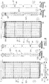
- Figs. 1a-b there is represented a known cylindrical horizontally disposed curd vat 1 which is supported by a number of legs 2.
- the end walls 3, 4 of the curd vat 1 are conical in this example, and through one of these end walls a drive shaft 5 extends centrally.
- This drive shaft which in this example is bearing-mounted in the opposite end wall, supports a cutting/stirring element 6 for cutting and stirring curd.
- a sealing element 7 Arranged between the drive shaft 5 and the wall 3 through which the shaft 5 extends into the curd vat is a sealing element 7. Outside the curd vat, the drive shaft 5 is connected by means of a coupling 8 to a drive shaft 9, which is connected via transmission means 10 to a drive motor 11.
- the motor 11 is arranged for rotating the cutting/stirring element 6 around the centerline of the curd vat 1 alternately in one direction (stirring) and the other direction (cutting).
- the curd vat 1 in its upper part has a manhole 13 which is covered by a manhole cover 13a.
- an opening 14 is provided which is intended for immersion of a whey sieve 15 in the curd vat 1.
- the whey sieve 15 is supported by a bent pipe 16 which is rotatably connected to the curd vat 1 at 17.
- the curd vat 1 has an outlet 18 at its lowest part. With P the customary level of the curd in the curd vat is indicated.
- the cutting/stirring element 6 comprises a number of cutting frames 19 which, next to each other, are connected with the drive shaft 5 and extend from the drive shaft 5 into the proximity of the inner side of the cylindrical vat wall 25.
- the cutting/stirring element comprises six cutting frames 19.
- the number of cutting frames 19 depends on the size of the curd vat.
- the cutting frames 19 are connected with the drive shaft so as to mutually form angles with each other, as can be clearly seen in Fig. 1b , and are placed along the drive shaft 5 so as to extend outwardly from the shaft in staggered relation.
- Each of the cutting frames 19 may further be fitted at an angle with respect to the centerline of the drive shaft 5, as is illustrated in Fig.
- the present invention can also be applied to differently designed curd vats and apparatuses having a similar function, i.e., cutting and/or stirring curd or similar substances.
- Figs. 1a-b show a (known) apparatus for cutting and/or stirring curd or similar substance, comprising a curd vat 1 having a rotatable drive shaft 5 and at least one cutting frame 19 extending radially from that drive shaft.
- Figs. 2a-c show schematically, in three views/sections, a known cutting frame 19 such as used in the apparatus shown in Figs. 1a-b .
- the known cutting frame 19 comprises a frame, in the form of two free-standing, parallel frame girders 26, for supporting a lattice of longitudinal knives 27, which extend outwardly with respect to the drive shaft 5, and transverse knives 28, which largely extend between those longitudinal knives.
- the transverse knives are welded to the frame girders 26 by means of welds 29.
- the ends of the longitudinal knives comprise transversely bent knife end sections 30 which are intended to counteract the formation of curd plaque on the inner side of the vat wall 25 (see Figs. 1a-b ).
- Figs. 3a-e show schematically (in different views/sections) a first exemplary embodiment of a cutting frame according to the invention, in which the frame 32 is U-shaped and comprises two side frame girders 32a which on one side are connected, directly or indirectly (for example, via projections welded on the drive shaft 5, see e.g. Fig. 2 ), with the drive shaft 5 and which - in contrast with the configuration from Fig. 2 - on the other side (in Fig. 3a the lower side) are connected with each other by means of an outer transverse frame girder 32b.
- the frame 32 is U-shaped and comprises two side frame girders 32a which on one side are connected, directly or indirectly (for example, via projections welded on the drive shaft 5, see e.g. Fig. 2 ), with the drive shaft 5 and which - in contrast with the configuration from Fig. 2 - on the other side (in Fig. 3a the lower side) are connected with each other by means of an outer transverse frame girder
- Fig. 3e shows an alternative embodiment of the frame 32, which is closed-shaped there in that the side frame girders 32a, as well as being connected with each other at the lower side (the outer side) via the outer transverse frame girder 32b, are also connected with each other at the upper side (the inner side), viz., by means of an inner transverse frame girder 32c.
- the frame 32 is thus closed-shaped, viz., more or less O- and/or rectangle-shaped.
- the transverse knives are not welded by their ends to the side frame girders 31a, but the transverse knives 28 are caught by their ends 34 by recesses 35 provided in the side frame girders 32a.
- Those recesses 35 are, for example, more or less, square-shaped, at an angle of 45°, and the ends 34 are caught therein in a form-closing manner with sufficient play.
- the longitudinal knives 27 are caught by recesses 36 provided in the transverse knives 28, in which they are caught in a form-closing manner with sufficient play.
- the recesses 35 in the side frame girders and the recesses 36 in the transverse knives 28 are designed in a form-closing manner such that substantial (rotation) movements about the longitudinal axis of the transverse and longitudinal knives, respectively, are prevented.
- the transverse and longitudinal knives, respectively preserve the proper position for stirring and cutting of the curd, viz., in the direction of movement of the cutting frame around the rotating drive shaft 5.
- the transverse knives and the recesses provided in the side frame girders are designed in a form-closing manner such that also substantial movements of the transverse knives 28 in longitudinal direction are prevented.
- the width of the ends 34 of the transverse knives 28 is smaller than that of the intermediate area of those transverse knives 28, so that the transverse knives 28 are caught and locked between the two side frame girders 32a.
- the longitudinal knives 27 are caught and locked, viz., in that - as Fig.
- 3c shows - the width of the ends 37 of the longitudinal knives 27 is narrower than the intermediate part, those ends 37 falling into recesses, provided in the - with respect to the rotation movement around the drive shaft 5 - inner (upper in the figures) and outer (lower in the figures) transverse knife, that are smaller than the corresponding recesses in the intermediate transverse knives 28.
- the outer transverse frame girder 32b - as is schematically represented in the figures - may be so designed that it comprises an at least slightly outwardly (in a direction away from the drive shaft) extending knife section 38 - or is connected therewith - over a substantial portion of the length (i.e., the distance between the two side frame girders 32a, parallel to the drive shaft 5) of that outer transverse frame girder.
- obliquely outwardly in the direction of the cylindrical curd vat wall 25, see Fig.
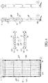
- Figs. 4a-g schematically show an embodiment in which the ends of the longitudinal knives 27 proximal to the drive shaft 5 are arrested (stopped) by the drive shaft 5, as shown in Figs. 4a-d , or a variant, shown in Figs. 4e-g , in which the ends of the longitudinal knives 27 proximal to the drive shaft 5 are arrested by an inner (upper in the figures) transverse frame girder 32c or inner transverse knife (in which no openings need to be provided then).
- ends of the longitudinal knives remote from the drive shaft 5 are arrested by the outer transverse frame girder 32b or the outer transverse knife (in which no openings need to be provided then).
- Fig. 5 shows the exemplary embodiment shown in Figs. 4a-d in perspective view.
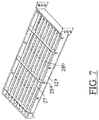
- Figs. 6a-d schematically show a fifth exemplary embodiment of a cutting frame according to the invention, in which the longitudinal knives 27 are caught by recesses provided in the transverse knives 28 (here indicated by 28a/b) which do not, as in the known cutting frame and also in the cutting frames according to the preceding exemplary embodiments, have closed openings (recesses) 36, but have half-open recesses 40 which are each open towards one side of the transverse knife 28a/b.
- transverse knives 28a/b are then alternately mounted in the side frame girders 32a (with their narrowed ends 34 locked in the recesses 35), such that the longitudinal knives 27 are caught by transverse knives 28a/b alternately having open sides of those recesses extending to one and the other side.
- This embodiment with half-open, alternately mounted transverse knives 28a/b provides advantages in particular as regards the assembly of the cutting frames, since the longitudinal knives 27 here do not need to be inserted through the (closed) openings in the transverse knives 27. Further, this is also a construction which is beneficial to hygiene, since it is less susceptible of accumulation of curd residues, bacteria, etc., and can be hosed clean better.
- FIG. 7 the exemplary embodiment shown in Figs. 6a-d is shown in perspective view.
- an apparatus and cutting frame respectively, which provides some clear constructional as well as process-technical improvements over the known apparatus. Owing to the proposed modification of the construction of the cutting frame, there are no welded joints necessary anymore (apart from any connecting pieces between the cutting frame proper and the drive shaft 5).
- the longitudinal knives 27 can be of simpler design than those in the known apparatus, viz., in that they are not provided anymore with (bent or welded-on) knife sections having portions extending transversely to the longitudinal direction thereof, while the function thereof - carrying along curd plaques forming on the wall of the tank or vat which are not carried along by the knives of the cutting frames - is yet preserved, indeed appreciably improved, in particular by virtue of the outwardly extending knife section 38 virtually throughout the width of the cutting frame.
- the invention may be describes as an apparatus for cutting and/or stirring curd or similar substance, comprising a curd vat 1 having a rotatable drive shaft 5 and at least one cutting frame 19 extending radially from that drive shaft,which cutting frame comprises a frame for supporting a lattice of longitudinal knives 27 which extend outwardly with respect to the drive shaft, and transverse knives 28 which extend largely between those longitudinal knives, wherein the frame 32 is substantially U- or closed-shaped, at least comprising two side frame girders 32a which on one side are directly or indirectly connected with the drive shaft and which on the other side are connected with each other via an outer transverse frame girder 32b.
- the transverse knives 28 can be caught by their ends 34 by recesses 35 provided in the side frame girders.
- the longitudinal knives 27 can be caught by recesses 36, 40 provided in the transverse knives 28.
- the longitudinal knives 27 can be caught by recesses 40 provided in the transverse knives 28, which are each open towards one side of the transverse knife, wherein the transverse knives can be mounted in the side frame girders such that the longitudinal knives can be caught by transverse knives alternately having open sides of those recesses extending to one and the other side.
- the recesses 35, 36, 40 in the side frame girders and in the transverse knives, respectively, can be designed in a form-closing manner such that substantial movements about the longitudinal axis of the transverse and longitudinal knives, respectively, are prevented.
- the transverse knives and the recesses provided in the side frame girders can be designed in a form-closing manner 34, 35 such that substantial movements of the transverse knives in their longitudinal direction are prevented.
- the ends of the longitudinal knives 27 proximal to the drive shaft 5 can be directly or indirectly arrested by the drive shaft.
- the ends of the longitudinal knives proximal to the drive shaft can be directly or indirectly arrested by an inner transverse frame girder 32c or inner transverse knife 28.
- an inner transverse frame girder 32c or inner transverse knife 28 recesses can be provided, wherein the ends 37 of the longitudinal knives 27 proximal to the drive shaft and the recesses provided in the inner transverse frame girder and the inner transverse knife, respectively, can be designed in a form-closing manner such that substantial movements of the longitudinal knives in their longitudinal direction towards the drive shaft or away from the drive shaft are prevented.
- the ends of the longitudinal knives remote from the drive shaft can be directly or indirectly arrested by the outer transverse frame girder 32b or the outer transverse knife 28.
- the outer transverse frame girder 32b or the outer transverse knife 28 recesses can be provided, wherein the ends 37 of the longitudinal knives remote from the drive shaft and the recesses provided in the outer transverse frame girder and the outer transverse knife, respectively, can be designed in a form-closing manner such that substantial movements of the longitudinal knives in their longitudinal direction towards the drive shaft or away from the drive shaft are prevented.
- the outer transverse frame girder 32b can comprise an at least slightly outwardly extending knife section 38, or is connected therewith, over a substantial portion of the length of that outer transverse frame girder.
- a cutting frame arranged for use in an apparatus as described above may be provided.
Landscapes
- Life Sciences & Earth Sciences (AREA)
- Animal Husbandry (AREA)
- Environmental Sciences (AREA)
- Food-Manufacturing Devices (AREA)
Claims (13)
- Vorrichtung zum Schneiden von Käsebruch, wobei die Vorrichtung aufweist
einen ersten longitudinalen Rahmenträger (32a) und einen zweiten longitudinalen Rahmenträger (32a), wobei jeder ein erstes Ende und ein zweites Ende aufweist, einen quer verlaufenden Rahmenträger (32b), welcher an dem ersten longitudinalen Rahmenträger und dem zweiten longitudinalen Rahmenträger jeweils befestigt ist, wodurch ein Rahmen gebildet wird,
eine Anzahl von quer verlaufenden Messern (28), welche zwischen dem ersten longitudinalen Rahmenträger (32a) und dem zweiten longitudinalen Rahmenträger (32a) angeordnet sind,
eine Anzahl von longitudinalen Messern (27), welche durch die quer verlaufenden Rahmenträger (32b) und die quer verlaufenden Messer (28) an Ort und Stelle gehalten wird,
wobei
der erste longitudinale Rahmenträger (32a) und der zweite longitudinale Rahmenträger (32a) mit Ausnehmungen (35) zur Aufnahme der quer verlaufenden Messer versehen ist, und
die quer verlaufenden Messer (28) mit Aussparungen (40) zur Aufnahme der longitudinalen Messer versehen sind. - Vorrichtung nach Anspruch 1, wobei das erste Ende des ersten longitudinalen Rahmenträgers und das erste Ende des zweiten longitudinalen Rahmenträgers dafür ausgelegt sind, um an einer Drehwelle eines Käsebottichs befestigt zu werden, und wobei die Anzahl von quer verlaufenden Messern durch den Rahmen an Ort und Stelle gehalten wird, wenn das erste Ende des ersten longitudinalen Rahmenträgers und das erste Ende des zweiten longitudinalen Rahmenträgers an der Drehwelle befestigt sind.
- Vorrichtung nach einem der vorhergehenden Ansprüche, wobei Enden der quer verlaufenden Messer mit Vorsprüngen versehen sind und der erste longitudinale Rahmenträger und der zweite longitudinale Rahmenträger mit Aussparungen zur Aufnahme der Vorsprünge versehen sind.
- Vorrichtung nach einem der vorhergehenden Ansprüche, wobei Enden der longitudinalen Messer mit Vorsprüngen versehen sind und der quer verlaufende Rahmenträger mit Aussparungen zur Aufnahme der Vorsprünge versehen ist.
- Vorrichtung nach einem der vorhergehenden Ansprüche, weiter aufweisend einen inneren, quer verlaufenden Rahmenträger, welcher in der Nähe des ersten Endes des ersten longitudinalen Rahmenträgers und des ersten Endes des zweiten longitudinalen Rahmenträgers jeweils befestigt ist.
- Vorrichtung nach Anspruch 5, wobei Enden der longitudinalen Messer mit Vorsprüngen versehen sind und der innere, quer verlaufende Rahmenträger mit Aussparungen zur Aufnahme der Vorsprünge versehen ist.
- Vorrichtung nach einem der vorhergehenden Ansprüche, weiter aufweisend einen Messerabschnitt, welcher an dem quer verlaufenden Rahmenträger befestigt ist, so dass Käsebruch dicht an einer Innenseite des Käsebottichs von der Innenseite losgerissen wird, wenn die Drehwelle in einer Schneidrichtung gedreht wird.
- Vorrichtung nach Anspruch 7, wobei der Messerabschnitt einen Endabschnitt aufweist, wobei ein Winkel zwischen dem Endabschnitt und dem ersten longitudinalen Rahmenträger und dem zweiten longitudinale Rahmenträger größer als 90 Grad ist.
- Käsebottich, aufweisend eine Schneidvorrichtung nach einem der Ansprüche 1 bis 8.
- Ausrüstungsteile für eine Schneidvorrichtung für einen Käsebottich, wobei die Ausrüstungsteile aufweisen eine Anzahl von longitudinalen Messern (27), und
eine Anzahl von quer verlaufenden Messern (28), welche mit Aussparungen (40) zur Aufnahme der longitudinalen Messer (27) versehen sind,
dadurch gekennzeichnet, dass Enden der quer verlaufenden Messer (28) mit Vorsprüngen versehen sind, so dass die quer verlaufenden Messer (28) durch einen ersten longitudinalen Rahmenträger (32a) und einen zweiten longitudinalen Rahmenträger (32a), welche mit Aussparungen (35) zur Aufnahme der Vorsprünge versehen sind, aufgenommen werden können. - Ausrüstungsteile nach Anspruch 10, wobei die Anzahl von quer verlaufenden Messern dafür ausgelegt ist, mit einem ersten longitudinalen Rahmenträger und einem zweiten longitudinalen Rahmenträger einer Vorrichtung nach einem der Ansprüche 1 bis 8 zu interagieren.
- Ausrüstungsteile nach Anspruch 10 oder 11, wobei Enden der longitudinalen Messer mit Vorsprüngen versehen sind, so dass die quer verlaufenden Messer von einem quer verlaufende Rahmenträger aufgenommen werden können, welcher mit Aussparungen zur Aufnahme der Vorsprünge versehen ist.
- Verfahren zum Montieren von Messern in einer Schneidevorrichtung für einen Käsebottich, wobei das Verfahren aufweist
Anordnen einer Anzahl von quer verlaufenden Messern (28) zwischen einem ersten longitudinalen Rahmenträger (32a) und einem zweiten longitudinalen Rahmenträger (32a), wobei die Anzahl von quer verlaufenden Messern (28) in Aussparungen (35) in dem ersten longitudinalen Rahmenträger (32a) und dem zweiten longitudinalen Rahmenträger (32a) aufgenommen wird, und
Anordnen einer Anzahl von longitudinalen Messern (27) durch Einschieben der Anzahl von longitudinalen Messern (27) in Aussparungen (40) der Anzahl von quer verlaufenden Messern (28).
Applications Claiming Priority (2)
| Application Number | Priority Date | Filing Date | Title |
|---|---|---|---|
| NL1038072A NL1038072C2 (nl) | 2010-06-28 | 2010-06-28 | Inrichting voor het snijden en/of roeren van wrongel. |
| PCT/EP2011/059690 WO2012000772A1 (en) | 2010-06-28 | 2011-06-10 | Apparatus for cutting and/or stirring curd |
Publications (2)
| Publication Number | Publication Date |
|---|---|
| EP2584890A1 EP2584890A1 (de) | 2013-05-01 |
| EP2584890B1 true EP2584890B1 (de) | 2018-07-25 |
Family
ID=43480942
Family Applications (1)
| Application Number | Title | Priority Date | Filing Date |
|---|---|---|---|
| EP11726114.9A Not-in-force EP2584890B1 (de) | 2010-06-28 | 2011-06-10 | Vorrichtung zum schneiden und/oder rühren von käsebruch |
Country Status (3)
| Country | Link |
|---|---|
| EP (1) | EP2584890B1 (de) |
| NL (1) | NL1038072C2 (de) |
| WO (1) | WO2012000772A1 (de) |
Family Cites Families (9)
| Publication number | Priority date | Publication date | Assignee | Title |
|---|---|---|---|---|
| US2663081A (en) * | 1951-06-06 | 1953-12-22 | Swift & Co | Cheese curd cutter |
| DE1738050U (de) * | 1956-11-13 | 1957-01-17 | Carl Karrer App Und Behaelterb | Einrichtung an rundkaesekesseln. |
| US3096582A (en) * | 1961-08-10 | 1963-07-09 | William F Mueller | Cheese cutter |
| DE2002428A1 (de) * | 1970-01-20 | 1971-07-29 | Conrad Lenz | Vorrichtung zur Herstellung von Kaese |
| FI68945C (fi) * | 1984-05-28 | 1985-12-10 | Mkt Tehtaat Oy | Ostkittel |
| NL1013083C2 (nl) * | 1999-09-17 | 2001-03-20 | Tetra Laval Holdings & Finance | Inrichting voor het snijden en roeren van wrongel. |
| NL1015016C2 (nl) | 2000-04-25 | 2001-10-26 | Tetra Laval Holdings & Finance | Inrichting voor het snijden en roeren van wrongel. |
| FI20022022A7 (fi) * | 2002-11-13 | 2004-05-14 | Mkt Finland Oy | Järjestely lankaleikkurin langanpään kiinnittämiseksi tukirakenteeseen ja lankaleikkuri |
| DK177919B1 (en) * | 2009-04-15 | 2015-01-05 | Tetra Laval Holdings & Finance | A cutting device having exchangeable knives |
-
2010
- 2010-06-28 NL NL1038072A patent/NL1038072C2/nl not_active IP Right Cessation
-
2011
- 2011-06-10 EP EP11726114.9A patent/EP2584890B1/de not_active Not-in-force
- 2011-06-10 WO PCT/EP2011/059690 patent/WO2012000772A1/en not_active Ceased
Non-Patent Citations (1)
| Title |
|---|
| None * |
Also Published As
| Publication number | Publication date |
|---|---|
| WO2012000772A1 (en) | 2012-01-05 |
| EP2584890A1 (de) | 2013-05-01 |
| NL1038072C2 (nl) | 2011-12-29 |
Similar Documents
| Publication | Publication Date | Title |
|---|---|---|
| EP2584890B1 (de) | Vorrichtung zum schneiden und/oder rühren von käsebruch | |
| US20160360925A1 (en) | Charcoal Grill Comprising a Height-Adjustable Charcoal Rack | |
| US7841271B2 (en) | Cheese vat for preparing soft fresh cheese, and cutting frame for a cheese vat | |
| CA2344087C (en) | Apparatus for cutting and stirring curd | |
| US20140096688A1 (en) | Apparatus for cutting and/or stirring curd | |
| US20150320007A1 (en) | Vertical vat with counter rotating agitator panels | |
| AU770894B2 (en) | Apparatus for cutting and stirring curd | |
| US5301605A (en) | Curd ripening apparatus | |
| CN107899463A (zh) | 一种稳固搅拌设备 | |
| KR101356852B1 (ko) | 우수 및 토사유입 방지장치 | |
| KR20120005291U (ko) | 배관 받침 캐리어 | |
| CN210809205U (zh) | 一种农业产品加工用分级清洗装置 | |
| FR2542588A1 (fr) | Dispositif et procede pour vider des matelas de lit a eau anti-vague | |
| BE647184A (de) | ||
| CN110089256A (zh) | 割晒机架、割晒机构和大蒜收获机 | |
| BE358600A (de) | ||
| FR2698759A1 (fr) | Refroidisseur de lait en vrac équipé d'un mécanisme et d'un outillage embarqué pour la fabrication fromagère. | |
| BE361376A (de) | ||
| JPH09298938A (ja) | コンバインにおけるノッターの取付構造 |
Legal Events
| Date | Code | Title | Description |
|---|---|---|---|
| PUAI | Public reference made under article 153(3) epc to a published international application that has entered the european phase |
Free format text: ORIGINAL CODE: 0009012 |
|
| 17P | Request for examination filed |
Effective date: 20121220 |
|
| AK | Designated contracting states |
Kind code of ref document: A1 Designated state(s): AL AT BE BG CH CY CZ DE DK EE ES FI FR GB GR HR HU IE IS IT LI LT LU LV MC MK MT NL NO PL PT RO RS SE SI SK SM TR |
|
| DAX | Request for extension of the european patent (deleted) | ||
| GRAP | Despatch of communication of intention to grant a patent |
Free format text: ORIGINAL CODE: EPIDOSNIGR1 |
|
| STAA | Information on the status of an ep patent application or granted ep patent |
Free format text: STATUS: GRANT OF PATENT IS INTENDED |
|
| INTG | Intention to grant announced |
Effective date: 20180220 |
|
| RIN1 | Information on inventor provided before grant (corrected) |
Inventor name: BOERTIEN, AREND |
|
| GRAS | Grant fee paid |
Free format text: ORIGINAL CODE: EPIDOSNIGR3 |
|
| GRAA | (expected) grant |
Free format text: ORIGINAL CODE: 0009210 |
|
| STAA | Information on the status of an ep patent application or granted ep patent |
Free format text: STATUS: THE PATENT HAS BEEN GRANTED |
|
| AK | Designated contracting states |
Kind code of ref document: B1 Designated state(s): AL AT BE BG CH CY CZ DE DK EE ES FI FR GB GR HR HU IE IS IT LI LT LU LV MC MK MT NL NO PL PT RO RS SE SI SK SM TR |
|
| REG | Reference to a national code |
Ref country code: GB Ref legal event code: FG4D |
|
| REG | Reference to a national code |
Ref country code: CH Ref legal event code: EP |
|
| REG | Reference to a national code |
Ref country code: AT Ref legal event code: REF Ref document number: 1020790 Country of ref document: AT Kind code of ref document: T Effective date: 20180815 |
|
| REG | Reference to a national code |
Ref country code: DE Ref legal event code: R096 Ref document number: 602011050334 Country of ref document: DE |
|
| REG | Reference to a national code |
Ref country code: IE Ref legal event code: FG4D |
|
| REG | Reference to a national code |
Ref country code: NL Ref legal event code: MP Effective date: 20180725 |
|
| REG | Reference to a national code |
Ref country code: LT Ref legal event code: MG4D |
|
| PG25 | Lapsed in a contracting state [announced via postgrant information from national office to epo] |
Ref country code: NL Free format text: LAPSE BECAUSE OF FAILURE TO SUBMIT A TRANSLATION OF THE DESCRIPTION OR TO PAY THE FEE WITHIN THE PRESCRIBED TIME-LIMIT Effective date: 20180725 |
|
| REG | Reference to a national code |
Ref country code: AT Ref legal event code: MK05 Ref document number: 1020790 Country of ref document: AT Kind code of ref document: T Effective date: 20180725 |
|
| PG25 | Lapsed in a contracting state [announced via postgrant information from national office to epo] |
Ref country code: GR Free format text: LAPSE BECAUSE OF FAILURE TO SUBMIT A TRANSLATION OF THE DESCRIPTION OR TO PAY THE FEE WITHIN THE PRESCRIBED TIME-LIMIT Effective date: 20181026 Ref country code: SE Free format text: LAPSE BECAUSE OF FAILURE TO SUBMIT A TRANSLATION OF THE DESCRIPTION OR TO PAY THE FEE WITHIN THE PRESCRIBED TIME-LIMIT Effective date: 20180725 Ref country code: PL Free format text: LAPSE BECAUSE OF FAILURE TO SUBMIT A TRANSLATION OF THE DESCRIPTION OR TO PAY THE FEE WITHIN THE PRESCRIBED TIME-LIMIT Effective date: 20180725 Ref country code: RS Free format text: LAPSE BECAUSE OF FAILURE TO SUBMIT A TRANSLATION OF THE DESCRIPTION OR TO PAY THE FEE WITHIN THE PRESCRIBED TIME-LIMIT Effective date: 20180725 Ref country code: LT Free format text: LAPSE BECAUSE OF FAILURE TO SUBMIT A TRANSLATION OF THE DESCRIPTION OR TO PAY THE FEE WITHIN THE PRESCRIBED TIME-LIMIT Effective date: 20180725 Ref country code: FI Free format text: LAPSE BECAUSE OF FAILURE TO SUBMIT A TRANSLATION OF THE DESCRIPTION OR TO PAY THE FEE WITHIN THE PRESCRIBED TIME-LIMIT Effective date: 20180725 Ref country code: BG Free format text: LAPSE BECAUSE OF FAILURE TO SUBMIT A TRANSLATION OF THE DESCRIPTION OR TO PAY THE FEE WITHIN THE PRESCRIBED TIME-LIMIT Effective date: 20181025 Ref country code: AT Free format text: LAPSE BECAUSE OF FAILURE TO SUBMIT A TRANSLATION OF THE DESCRIPTION OR TO PAY THE FEE WITHIN THE PRESCRIBED TIME-LIMIT Effective date: 20180725 Ref country code: NO Free format text: LAPSE BECAUSE OF FAILURE TO SUBMIT A TRANSLATION OF THE DESCRIPTION OR TO PAY THE FEE WITHIN THE PRESCRIBED TIME-LIMIT Effective date: 20181025 Ref country code: IS Free format text: LAPSE BECAUSE OF FAILURE TO SUBMIT A TRANSLATION OF THE DESCRIPTION OR TO PAY THE FEE WITHIN THE PRESCRIBED TIME-LIMIT Effective date: 20181125 |
|
| PG25 | Lapsed in a contracting state [announced via postgrant information from national office to epo] |
Ref country code: AL Free format text: LAPSE BECAUSE OF FAILURE TO SUBMIT A TRANSLATION OF THE DESCRIPTION OR TO PAY THE FEE WITHIN THE PRESCRIBED TIME-LIMIT Effective date: 20180725 Ref country code: HR Free format text: LAPSE BECAUSE OF FAILURE TO SUBMIT A TRANSLATION OF THE DESCRIPTION OR TO PAY THE FEE WITHIN THE PRESCRIBED TIME-LIMIT Effective date: 20180725 Ref country code: LV Free format text: LAPSE BECAUSE OF FAILURE TO SUBMIT A TRANSLATION OF THE DESCRIPTION OR TO PAY THE FEE WITHIN THE PRESCRIBED TIME-LIMIT Effective date: 20180725 |
|
| REG | Reference to a national code |
Ref country code: DE Ref legal event code: R097 Ref document number: 602011050334 Country of ref document: DE |
|
| PG25 | Lapsed in a contracting state [announced via postgrant information from national office to epo] |
Ref country code: EE Free format text: LAPSE BECAUSE OF FAILURE TO SUBMIT A TRANSLATION OF THE DESCRIPTION OR TO PAY THE FEE WITHIN THE PRESCRIBED TIME-LIMIT Effective date: 20180725 Ref country code: ES Free format text: LAPSE BECAUSE OF FAILURE TO SUBMIT A TRANSLATION OF THE DESCRIPTION OR TO PAY THE FEE WITHIN THE PRESCRIBED TIME-LIMIT Effective date: 20180725 Ref country code: RO Free format text: LAPSE BECAUSE OF FAILURE TO SUBMIT A TRANSLATION OF THE DESCRIPTION OR TO PAY THE FEE WITHIN THE PRESCRIBED TIME-LIMIT Effective date: 20180725 Ref country code: CZ Free format text: LAPSE BECAUSE OF FAILURE TO SUBMIT A TRANSLATION OF THE DESCRIPTION OR TO PAY THE FEE WITHIN THE PRESCRIBED TIME-LIMIT Effective date: 20180725 Ref country code: IT Free format text: LAPSE BECAUSE OF FAILURE TO SUBMIT A TRANSLATION OF THE DESCRIPTION OR TO PAY THE FEE WITHIN THE PRESCRIBED TIME-LIMIT Effective date: 20180725 |
|
| PG25 | Lapsed in a contracting state [announced via postgrant information from national office to epo] |
Ref country code: SK Free format text: LAPSE BECAUSE OF FAILURE TO SUBMIT A TRANSLATION OF THE DESCRIPTION OR TO PAY THE FEE WITHIN THE PRESCRIBED TIME-LIMIT Effective date: 20180725 Ref country code: DK Free format text: LAPSE BECAUSE OF FAILURE TO SUBMIT A TRANSLATION OF THE DESCRIPTION OR TO PAY THE FEE WITHIN THE PRESCRIBED TIME-LIMIT Effective date: 20180725 Ref country code: SM Free format text: LAPSE BECAUSE OF FAILURE TO SUBMIT A TRANSLATION OF THE DESCRIPTION OR TO PAY THE FEE WITHIN THE PRESCRIBED TIME-LIMIT Effective date: 20180725 |
|
| PLBE | No opposition filed within time limit |
Free format text: ORIGINAL CODE: 0009261 |
|
| STAA | Information on the status of an ep patent application or granted ep patent |
Free format text: STATUS: NO OPPOSITION FILED WITHIN TIME LIMIT |
|
| 26N | No opposition filed |
Effective date: 20190426 |
|
| PG25 | Lapsed in a contracting state [announced via postgrant information from national office to epo] |
Ref country code: SI Free format text: LAPSE BECAUSE OF FAILURE TO SUBMIT A TRANSLATION OF THE DESCRIPTION OR TO PAY THE FEE WITHIN THE PRESCRIBED TIME-LIMIT Effective date: 20180725 |
|
| REG | Reference to a national code |
Ref country code: DE Ref legal event code: R119 Ref document number: 602011050334 Country of ref document: DE |
|
| PG25 | Lapsed in a contracting state [announced via postgrant information from national office to epo] |
Ref country code: MC Free format text: LAPSE BECAUSE OF FAILURE TO SUBMIT A TRANSLATION OF THE DESCRIPTION OR TO PAY THE FEE WITHIN THE PRESCRIBED TIME-LIMIT Effective date: 20180725 |
|
| REG | Reference to a national code |
Ref country code: CH Ref legal event code: PL |
|
| GBPC | Gb: european patent ceased through non-payment of renewal fee |
Effective date: 20190610 |
|
| REG | Reference to a national code |
Ref country code: BE Ref legal event code: MM Effective date: 20190630 |
|
| PG25 | Lapsed in a contracting state [announced via postgrant information from national office to epo] |
Ref country code: TR Free format text: LAPSE BECAUSE OF FAILURE TO SUBMIT A TRANSLATION OF THE DESCRIPTION OR TO PAY THE FEE WITHIN THE PRESCRIBED TIME-LIMIT Effective date: 20180725 |
|
| PG25 | Lapsed in a contracting state [announced via postgrant information from national office to epo] |
Ref country code: IE Free format text: LAPSE BECAUSE OF NON-PAYMENT OF DUE FEES Effective date: 20190610 Ref country code: GB Free format text: LAPSE BECAUSE OF NON-PAYMENT OF DUE FEES Effective date: 20190610 Ref country code: DE Free format text: LAPSE BECAUSE OF NON-PAYMENT OF DUE FEES Effective date: 20200101 |
|
| PG25 | Lapsed in a contracting state [announced via postgrant information from national office to epo] |
Ref country code: CH Free format text: LAPSE BECAUSE OF NON-PAYMENT OF DUE FEES Effective date: 20190630 Ref country code: LU Free format text: LAPSE BECAUSE OF NON-PAYMENT OF DUE FEES Effective date: 20190610 Ref country code: BE Free format text: LAPSE BECAUSE OF NON-PAYMENT OF DUE FEES Effective date: 20190630 Ref country code: LI Free format text: LAPSE BECAUSE OF NON-PAYMENT OF DUE FEES Effective date: 20190630 |
|
| PG25 | Lapsed in a contracting state [announced via postgrant information from national office to epo] |
Ref country code: FR Free format text: LAPSE BECAUSE OF NON-PAYMENT OF DUE FEES Effective date: 20190630 Ref country code: PT Free format text: LAPSE BECAUSE OF FAILURE TO SUBMIT A TRANSLATION OF THE DESCRIPTION OR TO PAY THE FEE WITHIN THE PRESCRIBED TIME-LIMIT Effective date: 20181125 |
|
| PG25 | Lapsed in a contracting state [announced via postgrant information from national office to epo] |
Ref country code: CY Free format text: LAPSE BECAUSE OF FAILURE TO SUBMIT A TRANSLATION OF THE DESCRIPTION OR TO PAY THE FEE WITHIN THE PRESCRIBED TIME-LIMIT Effective date: 20180725 |
|
| PG25 | Lapsed in a contracting state [announced via postgrant information from national office to epo] |
Ref country code: MT Free format text: LAPSE BECAUSE OF FAILURE TO SUBMIT A TRANSLATION OF THE DESCRIPTION OR TO PAY THE FEE WITHIN THE PRESCRIBED TIME-LIMIT Effective date: 20180725 Ref country code: HU Free format text: LAPSE BECAUSE OF FAILURE TO SUBMIT A TRANSLATION OF THE DESCRIPTION OR TO PAY THE FEE WITHIN THE PRESCRIBED TIME-LIMIT; INVALID AB INITIO Effective date: 20110610 |
|
| PG25 | Lapsed in a contracting state [announced via postgrant information from national office to epo] |
Ref country code: MK Free format text: LAPSE BECAUSE OF FAILURE TO SUBMIT A TRANSLATION OF THE DESCRIPTION OR TO PAY THE FEE WITHIN THE PRESCRIBED TIME-LIMIT Effective date: 20180725 |