EP2587694A1 - Procédé et système de liaisons optiques sans fil intérieures - Google Patents
Procédé et système de liaisons optiques sans fil intérieures Download PDFInfo
- Publication number
- EP2587694A1 EP2587694A1 EP12175895.7A EP12175895A EP2587694A1 EP 2587694 A1 EP2587694 A1 EP 2587694A1 EP 12175895 A EP12175895 A EP 12175895A EP 2587694 A1 EP2587694 A1 EP 2587694A1
- Authority
- EP
- European Patent Office
- Prior art keywords
- user
- light
- optical
- unit
- central station
- Prior art date
- Legal status (The legal status is an assumption and is not a legal conclusion. Google has not performed a legal analysis and makes no representation as to the accuracy of the status listed.)
- Withdrawn
Links
- 230000003287 optical effect Effects 0.000 title claims abstract description 152
- 238000000034 method Methods 0.000 title claims description 70
- 230000006854 communication Effects 0.000 claims abstract description 92
- 238000004891 communication Methods 0.000 claims abstract description 92
- 230000005540 biological transmission Effects 0.000 claims description 6
- 230000002457 bidirectional effect Effects 0.000 claims 2
- 230000005855 radiation Effects 0.000 description 36
- 230000008569 process Effects 0.000 description 27
- 230000015654 memory Effects 0.000 description 23
- 239000000835 fiber Substances 0.000 description 15
- 238000012545 processing Methods 0.000 description 8
- 230000007175 bidirectional communication Effects 0.000 description 6
- 230000008878 coupling Effects 0.000 description 5
- 238000010168 coupling process Methods 0.000 description 5
- 238000005859 coupling reaction Methods 0.000 description 5
- 230000009977 dual effect Effects 0.000 description 4
- 238000010586 diagram Methods 0.000 description 3
- 238000012544 monitoring process Methods 0.000 description 3
- 238000012546 transfer Methods 0.000 description 3
- 230000008901 benefit Effects 0.000 description 2
- 239000004020 conductor Substances 0.000 description 2
- 238000005516 engineering process Methods 0.000 description 2
- 238000012986 modification Methods 0.000 description 2
- 230000004048 modification Effects 0.000 description 2
- 230000003071 parasitic effect Effects 0.000 description 2
- 230000001902 propagating effect Effects 0.000 description 2
- 238000001228 spectrum Methods 0.000 description 2
- 238000007792 addition Methods 0.000 description 1
- 238000013459 approach Methods 0.000 description 1
- 230000008859 change Effects 0.000 description 1
- 239000011248 coating agent Substances 0.000 description 1
- 238000000576 coating method Methods 0.000 description 1
- 238000012937 correction Methods 0.000 description 1
- 238000013461 design Methods 0.000 description 1
- 230000023004 detection of visible light Effects 0.000 description 1
- 239000011521 glass Substances 0.000 description 1
- 230000006872 improvement Effects 0.000 description 1
- 230000007787 long-term memory Effects 0.000 description 1
- 238000005259 measurement Methods 0.000 description 1
- 239000013307 optical fiber Substances 0.000 description 1
- 230000008520 organization Effects 0.000 description 1
- 230000008707 rearrangement Effects 0.000 description 1
- 230000035945 sensitivity Effects 0.000 description 1
- 230000006403 short-term memory Effects 0.000 description 1
- 230000003068 static effect Effects 0.000 description 1
- 238000006467 substitution reaction Methods 0.000 description 1
- 239000012780 transparent material Substances 0.000 description 1
- 230000000007 visual effect Effects 0.000 description 1
Images


Classifications
-
- H—ELECTRICITY
- H04—ELECTRIC COMMUNICATION TECHNIQUE
- H04B—TRANSMISSION
- H04B10/00—Transmission systems employing electromagnetic waves other than radio-waves, e.g. infrared, visible or ultraviolet light, or employing corpuscular radiation, e.g. quantum communication
- H04B10/11—Arrangements specific to free-space transmission, i.e. transmission through air or vacuum
- H04B10/114—Indoor or close-range type systems
- H04B10/1149—Arrangements for indoor wireless networking of information
Definitions
- invisible light source 202 may be an infrared laser diode and may radiate, for example, at a wavelength of 1550 nm.
- the radiation from invisible light source 202 may be used for carrying data towards one or more user receivers 220, 221 or 222.
- visible light source 203 may be a red laser diode and may radiate at a wavelength of 650 nm.
- the radiation from visible light source 203 may be coupled to the light from invisible light source 202 in order to visualize the propagation of the invisible light, e.g., the infra red light, for setting the optical connection between transceiver 212 and each one of user modules 220-223.
- Photo detector 204 may be used for detecting or sensing light originated from one or more user modules 220-223.
- optical module 211 may include a plurality of optical elements, devices and, means to couple, join, link or set the light originated from visible light source 203 and the light originated from invisible light source 202 such that both radiations may have a substantially identical optical axis. Coupling the two light radiations may allow a human to observe the visible light, e.g., red light coming from visible light source 203, to align its direction and by that to align the direction of the invisible light, e.g., infrared light, coming from invisible light source 202 which is invisible to the human eye. During the alignment process, the position of each one of user modules 220-223 may be adjusted, altered or tuned in order to align the invisible light by observing the visible light coming from visible light source 203 as described in embodiments of the invention.
- system 200 may include any suitable numbers of user modules.
- optical module 211 may include a multiple-mirror-element for directing the light towards a plurality of user modules, it should be understood to a person skilled in art that the invention is not limited in this respect and according to other embodiments of the present invention, optical module 211 may include any suitable optical elements or devices, for example, as presented in Figs.6-11 .
- Fig. 2 represents only one exemplary system which may implement or execute the invention described herein and the scope of the present invention is not limited in this respect.
- Other systems or implementations which may carry out the present invention may be used.
- other optical systems using various optical modules and/or components such as circulators, splitters, pigtailed fibers, and the like may be used.
- Some exemplary systems which may all implement embodiments of the invention are described with reference to Figs. 6-11 .
- the visible light spot created by each sub beam on surfaces in the space and on central station window 370 may be visible spot which the human eye can observe.
- the visible spot may have characteristics such as a specific color according to the visible light source 203, for example, if a red laser diode is being used a red light spot may be observed, however any visible light other than red light may be used.
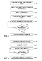
- the method may include adjusting, altering, modifying, tuning or moving the position of the user module such that the visible light originating from the central station and the visible light originating from the user module, or reflected from the user module, overlap, convene, meet or align.
- the user module may be adjusted, rotated, twisted such that the light spot created by the light originating from the central station on the alignment window of the central station, e.g., window 370 of Fig. 3 , and light spot created by the light originating from the user module on the alignment window of the central station overlaps.
- the method may include measuring the power of the radiation detected or sensed by the photo detector of the user module, e.g., by photo detector 312 of Fig. 3 .
- Photo detector 312 may measure the power of the light originated from the invisible light source of the central unit.
- the method may include monitoring the invisible and/or visible radiation originating from the central station and measuring the detected power of the radiation arriving to the photo detector of the user module.
- Other embodiments, additionally or alternatively, may include measuring the power of the radiation detected or sensed by the photo detector of the central station, e.g., by photo detector 204 of Fig. 2 .
- user module may include angular alignment means, such as screws, allowing user module to be adjusted in angular directions, e.g., in Qx, Qy and Qz angles.
- User module additionally or alternatively, may be moved along horizontal and vertical directions in order to find the preferred position, namely, the position in which a maximal power is detected.
- user module may include a positioning unit which may adjust a spatial position of the user unit relative to the central unit, e.g., until a maximal power is measured.
- the positioning unit may be coupled to, attached to or embedded within user unit.
- the method may include checking if a maximum power is reached and detected in order to achieve optimal alignment. If a peek of the power is reached and measured the method may include locking and/or fastening the user module to its current position in order to keep the optimal alignment reached as indicated at box 550. If a peek of the power has not reached the method may include further adjustment of the user module position as indicated by returning to box 530. Further adjustment of the position of the user module followed by a power measurement may be performed periodically until a maximum power may be detected as indicated at box 540.
- an optimal alignment may be controlled and achieved by detecting maximal invisible light signal on one of the central station and user module or by both of the central station and user module, e.g., by detecting and measuring the invisible light signal power on both the user module and the central station.
- An optical system 700 may include a central station 710 and a plurality of user modules, e.g., user module 771 and user module 772.
- Central station 710 may include an invisible light source 703 as the transmitter, a photo detector 704 as the receiver and a visible light source 702.
- Each of user modules 771 and 772 may include an invisible light source 788 as the transmitter and a photo detector 782 as the receiver.
- each of user modules 771 and 772 may further include a visible light source (not shown).
- Central station 710 may further include an optical circulator 706, e.g., a fiber circulator, having a plurality of ports.
- Circulator 706 may be connected to invisible light source 703 via port 1 of circulator 706 and to photo detector 704 via a filter 722 and port 3 of the circulator. If light enters via port 1 of circulator 706, it exits via port 2 of circulator 706 while if light enters via port 2 of circulator 706, it exits via port 3 of circulator 706.
- Filter 722 may prevent parasitic return losses of certain wavelengths from entering photo detector 704.
- Such a filter may split the signal coming from the user module and allow only signals at a desired wavelength, to reach photo detector 704. For example, splitting light originating from user module 772, into two wavelengths, a first of 1490 nm and a second of 1550 nm and allow only pure signals at a desired wavelength, for example, at 1490 nm to reach photo detector 704.
- the visible light reflected from the user module or originated from a visible light source in the user module may enable a simple and quick alignment process.
- the invisible portion of the light beam (for example, at 1550 nm) may be transferred via port 3 of user circulator 781 through the user filter 783 to user photo detector 782.
- Fig. 7A illustrates a dual wavelength objective lens module of a central station according to embodiments of the invention.
- a dual wavelength objective lens module 720 is a detailed illustration of each one of objective lens module 720 of Fig. 7 .
- Objective lens module 720 may be used for collimating both invisible light and visible light, for example, infrared light and red light.
- Objective lens module 720 may include a window 721, a collimating lens 732 and optical means to couple the light from invisible light source, e.g., invisible light source 703 of Fig. 7 , and visible light from visible light source, e.g., visible light source 702 of Fig. 7 .
- Another exemplary transceiver 880 may be a user module transceiver 820.
- invisible light source module 811 may emit light at, for example, wavelength of 1490 nm and photo detector 814 may be configured to detect light at a different wavelength, for example at 1310 nm.
- Optical filter 813 may be configured to transmit light at wavelength 1490 nm originated from invisible light source module 811 and reflect the light beam originated from a central station, e.g., central station 800 at a wavelength of, for example, 1310 nm, and direct it to photo detector 814.
- the anti-reflecting (AR) coating for these optical elements may be chosen to be at wide bandwidths covering both wavelengths.
- the beam originated from the invisible light source of transceiver 810 may be mixed with a visible light beam, e.g., red light beam radiated at, for example, 650nm from visible light source 840.
- the visible light may be used for alignment purposes and may be coupled to the invisible light by combiner 830.
- the joint dual wavelength radiation may be coupled to splitter 850.
- Optical module 860 may consist of a plurality of objectives 861. Each optical module 861 may have mechanical angular alignment means that enable to direct it to the desired user transceiver module.
- the design of the elements may be determined such that the visible output beam may be collimated while both invisible beams, e.g., light at 1310 nm and 1490 nm, may be diverged.
- the collimated visible light beam may be used for alignment of the transceiver of the central station, e.g., transceiver 810 of Fig. 8A to the transceiver of the user module, e.g., transceiver 820 of Fig. 8A .
- the coupling efficiency for both the central station and user receivers using diverging invisible beams may be reduced relative to using collimated beams by, for example, about 10dB while the angular alignment sensitivity is substantially reduces from 0.05deg to 0.5deg.
- the visible light from central station 910 may be used for positioning of user module 909 at a desired place, e.g., on a table, wall or other surface, also referred to herein as "coarse alignment” or "rough alignment".
- User module 909 may be located such that a visible light spot created by the visible light originated from central station 910 is directed to the center of the user window 1003.
- the visible light originated at user module 909 may be used for "fine alignment”.
- the light originated from user module 909 may be directed to the center of window 1004 of central station 910. According to embodiments of the invention, the visible light coming from user module 909 may be further used for fine tuning of the alignment.
- Optical elements 1005 and 1006 may be used during automated or automatic fine tuning which may be performed by changing, adjusting or tilting the angular position of optical elements 1005 and 1006.
- the alignment process may use visible light for reaching alignment as described in embodiments of the invention and/or may use invisible light by detecting, monitoring and measuring the invisible and/or visible radiation originating from the central station and measuring the detected power of the radiation arriving to the photo detector of the user module and/or measuring the invisible and/or visible radiation originating from the user module and measuring the detected power of the radiation arriving to the photo detector of the central station.
Landscapes
- Engineering & Computer Science (AREA)
- Computing Systems (AREA)
- Physics & Mathematics (AREA)
- Electromagnetism (AREA)
- Computer Networks & Wireless Communication (AREA)
- Signal Processing (AREA)
- Optical Communication System (AREA)
Applications Claiming Priority (2)
| Application Number | Priority Date | Filing Date | Title |
|---|---|---|---|
| US201161550612P | 2011-10-24 | 2011-10-24 | |
| US201161568170P | 2011-12-08 | 2011-12-08 |
Publications (1)
| Publication Number | Publication Date |
|---|---|
| EP2587694A1 true EP2587694A1 (fr) | 2013-05-01 |
Family
ID=46762827
Family Applications (1)
| Application Number | Title | Priority Date | Filing Date |
|---|---|---|---|
| EP12175895.7A Withdrawn EP2587694A1 (fr) | 2011-10-24 | 2012-07-11 | Procédé et système de liaisons optiques sans fil intérieures |
Country Status (4)
| Country | Link |
|---|---|
| US (1) | US8948601B2 (fr) |
| EP (1) | EP2587694A1 (fr) |
| JP (1) | JP5469213B2 (fr) |
| BR (1) | BR102012019486A2 (fr) |
Cited By (2)
| Publication number | Priority date | Publication date | Assignee | Title |
|---|---|---|---|---|
| WO2018042370A3 (fr) * | 2016-09-02 | 2018-07-12 | King Abdullah University Of Science And Technology | Récepteur non associé à une imagerie utilisant des miroirs dans un système de communication sans fil |
| WO2018219656A1 (fr) * | 2017-05-31 | 2018-12-06 | Osram Gmbh | Mise à disposition d'une connexion de communication sans fil entre au moins un terminal de communication positionné dans une région d'espace prédéfinie et un réseau de communication |
Families Citing this family (19)
| Publication number | Priority date | Publication date | Assignee | Title |
|---|---|---|---|---|
| JP2014103488A (ja) * | 2012-11-19 | 2014-06-05 | Sony Corp | 通信装置およびプログラム |
| WO2014155149A1 (fr) * | 2013-03-25 | 2014-10-02 | Nokia Corporation | Établissement d'une liaison optique |
| KR20150000041A (ko) * | 2013-06-21 | 2015-01-02 | 삼성전자주식회사 | 전자 기기의 보호 커버 |
| KR102106315B1 (ko) * | 2014-06-19 | 2020-05-06 | 한국전자통신연구원 | 다계층 네트워크에서 링크 관리 방법 및 장치 |
| JP6434724B2 (ja) * | 2014-07-01 | 2018-12-05 | パナソニック インテレクチュアル プロパティ コーポレーション オブ アメリカPanasonic Intellectual Property Corporation of America | 情報通信方法 |
| US9432117B2 (en) * | 2014-12-29 | 2016-08-30 | Industrial Technology Research Institute | Visible light communication apparatus and method of visible light communication |
| DE102015221283B4 (de) * | 2015-10-30 | 2017-09-14 | Deutsches Zentrum für Luft- und Raumfahrt e.V. | Sender für ein optisches Freistrahl-Kommunikations-System und zugehöriges Empfängerterminal |
| CN115242304B (zh) | 2015-12-30 | 2024-09-13 | 艾伦神火公司 | 用于光学窄播的系统和方法 |
| WO2018097798A1 (fr) * | 2016-11-23 | 2018-05-31 | Agency For Science, Technology And Research | Dispositif de communication à diodes électroluminescentes, procédé de formation et d'utilisation de celui-ci |
| CN106506093B (zh) * | 2016-11-28 | 2019-09-06 | 中车株洲电力机车研究所有限公司 | 一种fso通信系统 |
| US10181241B2 (en) * | 2017-04-04 | 2019-01-15 | Qualcomm Incorporated | Modulated warning lights for vehicles |
| US9853740B1 (en) | 2017-06-06 | 2017-12-26 | Surefire Llc | Adaptive communications focal plane array |
| US10473439B2 (en) | 2018-01-05 | 2019-11-12 | Aron Surefire, Llc | Gaming systems and methods using optical narrowcasting |
| US10250948B1 (en) | 2018-01-05 | 2019-04-02 | Aron Surefire, Llc | Social media with optical narrowcasting |
| US10236986B1 (en) | 2018-01-05 | 2019-03-19 | Aron Surefire, Llc | Systems and methods for tiling free space optical transmissions |
| US10983344B2 (en) | 2018-08-10 | 2021-04-20 | 8 Rivers Capital, Llc. | System for optical wireless communication to extended reality immersion device |
| JP7240715B2 (ja) * | 2019-01-30 | 2023-03-16 | 株式会社オーディオテクニカ | 光照射装置とワイヤレスマイクロホン |
| CN111835416B (zh) * | 2019-04-15 | 2022-07-12 | Oppo广东移动通信有限公司 | 电子设备之间的通信系统、方法以及电子设备 |
| EP4029163B1 (fr) * | 2019-09-13 | 2023-06-28 | Signify Holding B.V. | Systèmes et procédés permettant un transfert de fichiers sans fil à grande vitesse |
Citations (8)
| Publication number | Priority date | Publication date | Assignee | Title |
|---|---|---|---|---|
| JPS62110339A (ja) * | 1985-11-08 | 1987-05-21 | Nec Corp | 光送受信器 |
| EP0355952A2 (fr) * | 1988-08-24 | 1990-02-28 | Stc Plc | Système de communication optique |
| WO1992013402A1 (fr) * | 1991-01-16 | 1992-08-06 | Bicc Communications, Inc. | Dispositif et procede de recomposition automatique d'un systeme de reseau local en espace libre |
| US5600471A (en) * | 1994-04-28 | 1997-02-04 | Victor Company Of Japan, Ltd. | Optical wireless data transmission system and optical wireless data transmitting/receiving apparatus |
| US20020033981A1 (en) * | 2000-09-20 | 2002-03-21 | Keller Robert C. | Optical wireless multiport hub |
| US20050031350A1 (en) * | 2003-08-05 | 2005-02-10 | Ilan Haber | Miniature optical free space transceivers |
| WO2006046087A1 (fr) * | 2004-10-26 | 2006-05-04 | Freewire Communications Limited | Systeme de communications optique a faisceau divergeant |
| GB2460252A (en) * | 2008-05-21 | 2009-11-25 | Hewlett Packard Development Co | Alignment system for freespace QKD in which a receiver transmits an alignment beam and detects a retro-reflected version of the beam |
Family Cites Families (11)
| Publication number | Priority date | Publication date | Assignee | Title |
|---|---|---|---|---|
| JPS6297438A (ja) * | 1985-10-23 | 1987-05-06 | Nec Corp | 光送受信器 |
| JPS62100339A (ja) | 1985-10-24 | 1987-05-09 | Minolta Camera Co Ltd | 複写機 |
| US5218356A (en) * | 1991-05-31 | 1993-06-08 | Guenther Knapp | Wireless indoor data relay system |
| JP3059870B2 (ja) | 1992-10-16 | 2000-07-04 | 日本ビクター株式会社 | 光無線送受信装置及び光無線装置並びに光無線装置の光軸調整方法 |
| JP2003273809A (ja) | 2002-03-12 | 2003-09-26 | Canon Inc | 光空間通信装置および光空間通信システム |
| JP2003309524A (ja) | 2002-04-18 | 2003-10-31 | Canon Inc | 光空間伝送装置及びそれを用いた光伝送システム |
| JP2005101853A (ja) | 2003-09-24 | 2005-04-14 | Fuji Xerox Co Ltd | 光送信装置および光無線装置 |
| JP3823976B2 (ja) * | 2004-03-17 | 2006-09-20 | 日本ビクター株式会社 | 光無線伝送システム及び光無線伝送装置 |
| JP2007060308A (ja) * | 2005-08-24 | 2007-03-08 | Matsushita Electric Ind Co Ltd | 光空間伝送システム |
| KR100810297B1 (ko) * | 2006-10-31 | 2008-03-06 | 삼성전자주식회사 | 휴대용 무선 단말기의 무선 통신 인터페이스 |
| US20090154934A1 (en) * | 2007-12-18 | 2009-06-18 | Motorola, Inc. | Optical Transceiver Method and Apparatus |
-
2012
- 2012-07-10 US US13/545,008 patent/US8948601B2/en not_active Expired - Fee Related
- 2012-07-11 EP EP12175895.7A patent/EP2587694A1/fr not_active Withdrawn
- 2012-07-12 JP JP2012156712A patent/JP5469213B2/ja not_active Expired - Fee Related
- 2012-08-03 BR BR102012019486A patent/BR102012019486A2/pt not_active IP Right Cessation
Patent Citations (8)
| Publication number | Priority date | Publication date | Assignee | Title |
|---|---|---|---|---|
| JPS62110339A (ja) * | 1985-11-08 | 1987-05-21 | Nec Corp | 光送受信器 |
| EP0355952A2 (fr) * | 1988-08-24 | 1990-02-28 | Stc Plc | Système de communication optique |
| WO1992013402A1 (fr) * | 1991-01-16 | 1992-08-06 | Bicc Communications, Inc. | Dispositif et procede de recomposition automatique d'un systeme de reseau local en espace libre |
| US5600471A (en) * | 1994-04-28 | 1997-02-04 | Victor Company Of Japan, Ltd. | Optical wireless data transmission system and optical wireless data transmitting/receiving apparatus |
| US20020033981A1 (en) * | 2000-09-20 | 2002-03-21 | Keller Robert C. | Optical wireless multiport hub |
| US20050031350A1 (en) * | 2003-08-05 | 2005-02-10 | Ilan Haber | Miniature optical free space transceivers |
| WO2006046087A1 (fr) * | 2004-10-26 | 2006-05-04 | Freewire Communications Limited | Systeme de communications optique a faisceau divergeant |
| GB2460252A (en) * | 2008-05-21 | 2009-11-25 | Hewlett Packard Development Co | Alignment system for freespace QKD in which a receiver transmits an alignment beam and detects a retro-reflected version of the beam |
Cited By (6)
| Publication number | Priority date | Publication date | Assignee | Title |
|---|---|---|---|---|
| WO2018042370A3 (fr) * | 2016-09-02 | 2018-07-12 | King Abdullah University Of Science And Technology | Récepteur non associé à une imagerie utilisant des miroirs dans un système de communication sans fil |
| EP3793105A1 (fr) * | 2016-09-02 | 2021-03-17 | King Abdullah University Of Science And Technology | Récepteur non associé à une imagerie utilisant des miroirs dans un système de communication sans fil |
| US11018764B2 (en) | 2016-09-02 | 2021-05-25 | King Abdullah University Of Science And Technology | Non-imaging receiver utilizing mirrors in optical wireless communication system |
| WO2018219656A1 (fr) * | 2017-05-31 | 2018-12-06 | Osram Gmbh | Mise à disposition d'une connexion de communication sans fil entre au moins un terminal de communication positionné dans une région d'espace prédéfinie et un réseau de communication |
| CN110710333A (zh) * | 2017-05-31 | 2020-01-17 | 欧司朗有限责任公司 | 在定位于可预给定空间区域中的至少一个通信终端与通信网络之间提供无线通信连接 |
| US10931373B2 (en) | 2017-05-31 | 2021-02-23 | Osram Gmbh | Wireless communication link between at least one communication terminal device positioned in a predeterminable region and a communication network |
Also Published As
| Publication number | Publication date |
|---|---|
| US20130101285A1 (en) | 2013-04-25 |
| BR102012019486A2 (pt) | 2013-10-08 |
| JP5469213B2 (ja) | 2014-04-16 |
| US8948601B2 (en) | 2015-02-03 |
| JP2013093835A (ja) | 2013-05-16 |
Similar Documents
| Publication | Publication Date | Title |
|---|---|---|
| US8948601B2 (en) | Method and system for indoor wireless optical links | |
| US5142400A (en) | Method and apparatus for automatic acquisition and alignment of an optical beam communication link | |
| US5777768A (en) | Multiple transmitter laser link | |
| US7079774B2 (en) | Free-space optical communication system | |
| US10180543B2 (en) | Optical path control system and optical module | |
| US9515729B2 (en) | Omnidirectional free space optical communications receiver | |
| EP1130808B1 (fr) | Procédé et dispositif d'alignement automatique d'un signal optique dans un système de communication optique sans fil | |
| US6944403B2 (en) | MEMS based over-the-air optical data transmission system | |
| CN105897347A (zh) | 用太赫波的无线数据传输 | |
| Mai et al. | Beaconless angle-of-arrival tracking with improved receiver sensitivity and tracking precision for free-space optical communications | |
| Liu et al. | Effective auto-alignment and tracking of transceivers for visible-light communication in data centres | |
| Glushko et al. | Gigabit optical wireless communication system for personal area networking | |
| CN103067088A (zh) | 用于室内无线光学链路的方法和系统 | |
| CN101136698B (zh) | 多移动平台间的自由空间光通信系统 | |
| US20040208597A1 (en) | Free-Space optical transceiver link | |
| US8090264B2 (en) | Architecture for enabling network centric communications, sensing, computation, and information assurance | |
| CN113162690B (zh) | 空间激光通信检测装置及方法 | |
| US7181143B2 (en) | Free space optics communication apparatus and free space optics communication system | |
| JP6296436B2 (ja) | 光空間通信システム | |
| US11841433B2 (en) | Method and apparatus for determining at least one spatial position and orientation of at least one tracked measuring device | |
| CN210775847U (zh) | 一种激光雷达系统 | |
| US10374720B2 (en) | Light guide arrangement for a mobile communications device for optical data transmission, mobile communications device and method for optical data transmission | |
| Freitas et al. | Integrated Fiber Coupling and Position Sensing for FSO Communications Using Multi-Core Fibers | |
| CN107314754A (zh) | 一种方位角传递方法与装置 | |
| JP2003309524A (ja) | 光空間伝送装置及びそれを用いた光伝送システム |
Legal Events
| Date | Code | Title | Description |
|---|---|---|---|
| PUAI | Public reference made under article 153(3) epc to a published international application that has entered the european phase |
Free format text: ORIGINAL CODE: 0009012 |
|
| AK | Designated contracting states |
Kind code of ref document: A1 Designated state(s): AL AT BE BG CH CY CZ DE DK EE ES FI FR GB GR HR HU IE IS IT LI LT LU LV MC MK MT NL NO PL PT RO RS SE SI SK SM TR |
|
| AX | Request for extension of the european patent |
Extension state: BA ME |
|
| 17P | Request for examination filed |
Effective date: 20131029 |
|
| RBV | Designated contracting states (corrected) |
Designated state(s): AL AT BE BG CH CY CZ DE DK EE ES FI FR GB GR HR HU IE IS IT LI LT LU LV MC MK MT NL NO PL PT RO RS SE SI SK SM TR |
|
| RAP1 | Party data changed (applicant data changed or rights of an application transferred) |
Owner name: RIT WIRELESS LTD. |
|
| 17Q | First examination report despatched |
Effective date: 20160509 |
|
| STAA | Information on the status of an ep patent application or granted ep patent |
Free format text: STATUS: THE APPLICATION IS DEEMED TO BE WITHDRAWN |
|
| 18D | Application deemed to be withdrawn |
Effective date: 20160920 |