EP2592297A1 - Unité de force centrifuge et couplage - Google Patents
Unité de force centrifuge et couplage Download PDFInfo
- Publication number
- EP2592297A1 EP2592297A1 EP11188942.4A EP11188942A EP2592297A1 EP 2592297 A1 EP2592297 A1 EP 2592297A1 EP 11188942 A EP11188942 A EP 11188942A EP 2592297 A1 EP2592297 A1 EP 2592297A1
- Authority
- EP
- European Patent Office
- Prior art keywords
- centrifugal force
- component
- unit
- centrifugal
- clutch
- Prior art date
- Legal status (The legal status is an assumption and is not a legal conclusion. Google has not performed a legal analysis and makes no representation as to the accuracy of the status listed.)
- Withdrawn
Links
Images


Classifications
-
- F—MECHANICAL ENGINEERING; LIGHTING; HEATING; WEAPONS; BLASTING
- F16—ENGINEERING ELEMENTS AND UNITS; GENERAL MEASURES FOR PRODUCING AND MAINTAINING EFFECTIVE FUNCTIONING OF MACHINES OR INSTALLATIONS; THERMAL INSULATION IN GENERAL
- F16D—COUPLINGS FOR TRANSMITTING ROTATION; CLUTCHES; BRAKES
- F16D43/00—Automatic clutches
- F16D43/02—Automatic clutches actuated entirely mechanically
- F16D43/04—Automatic clutches actuated entirely mechanically controlled by angular speed
- F16D43/06—Automatic clutches actuated entirely mechanically controlled by angular speed with centrifugal masses actuating axially a movable pressure ring or the like
- F16D43/08—Automatic clutches actuated entirely mechanically controlled by angular speed with centrifugal masses actuating axially a movable pressure ring or the like the pressure ring actuating friction plates, cones or similar axially-movable friction surfaces
- F16D43/12—Automatic clutches actuated entirely mechanically controlled by angular speed with centrifugal masses actuating axially a movable pressure ring or the like the pressure ring actuating friction plates, cones or similar axially-movable friction surfaces the centrifugal masses acting on, or forming a part of, an actuating mechanism by which the pressure ring can also be actuated independently of the masses
Definitions
- Embodiments relate to a centrifugal force unit and a clutch, as they can be used for example in the automotive sector and here for example in passenger cars and racing.
- centrifugal clutch that automatically engages the vehicle.
- Conventional centrifugal clutches are based, for example, on radially opening jaws or disk packs, which are actuated via centrifugal levers.
- the DE 10 2004 030 280 A1 refers to a centrifugal clutch in which is pressed in a housing assembly via rolling elements and acting as a lever mechanism diaphragm spring of a pressure plate against a clutch disc.
- the diaphragm spring is arranged inside the housing of the centrifugal clutch.
- the centrifugal clutch described in this document allows no immediate gear change, as this centrifugal clutch can not be separated specifically.
- a centrifugal force unit for a clutch of a motor vehicle comprises a first component, a second component which is rotationally fixedly coupled to the first component relative to an axial direction, wherein the first component and the second component are formed such that a distance between the first component and the second component along the axial direction when exceeding a limit speed, starting from a rest value at a standstill of the centrifugal unit increases, and a return spring element, which causes a force between the first component and the second component such that the distance between the first Component and the second component at the standstill of the centrifugal unit assumes the quiescent value.
- the second component is in this case designed to provide with a clutch disc of the clutch a mechanical connection for transmitting a torque, wherein the first component is designed to be in contact with or brought into contact with a anpresskraftinden element of the clutch the increase in the distance between the first component and the second component is created or reinforced by the Anpresskraftallde element mechanical connection to the clutch disc.
- a clutch for a motor vehicle includes a clutch disc, such a centrifugal force unit according to the embodiment, a Anpresskraftdes element, which is formed so that when increasing the distance of the first component of the second component of the centrifugal force unit, a contact force along the axial direction of the Centrifugal unit and the clutch disc is applied, so that the torque is transferable, a housing basket, which is rotatably connected to the anpresskraftinden element and the centrifugal force unit, and a disengaging unit, which is arranged and formed so that by the disengaging unit exerted by the anpresskraftjob element contact pressure can be suppressed or reduced so that the mechanical connection between the clutch disc and the centrifugal force unit is separable.
- a centrifugal force unit for a clutch according to an embodiment and a clutch for a motor vehicle according to an embodiment is based on the finding that a targeted separation of the clutch, for example for a gear change, can be achieved by the fact that the first component of the centrifugal force unit is designed and arranged in that it is in contact with or can be brought into contact with the pressing force-generating element of the coupling so that, by increasing the distance between the first component and the second component, the mechanical connection to the coupling disc of the coupling is created by the contact force-generating element thereof is reinforced.
- the pressing force can be transmitted through the Anpresskraftinde element via the first member and the second component of the centrifugal force unit on the clutch disc of the clutch, so as to provide the mechanical connection for transmitting the torque.
- the clutch can be engaged via the pressing force-generating element of the same.
- the mechanical connection for transmitting a torque can be done by creating a frictional or frictional connection.
- a frictional or frictional connection comes about here by stiction, which thus requires a normal force component between the connection partners.
- the normal force component is in this case effected by the Anpresskraft-de element of the clutch in the form of the contact force, the mediates via the first component and the other components of the centrifugal force unit, the second component of the centrifugal force unit against a friction surface of the clutch disc, so as to the mechanical connection for transmitting the torque create.
- the first and / or the second component are often configured substantially plate-shaped or disc-shaped for this purpose.
- the second component generally has a contact surface on a side facing the clutch disk of the clutch, which contact surface is, for example, at least partially ring-shaped or annular.
- the contact surface is often oriented substantially perpendicular to the axial direction.
- the first and the second component can thus form in the assembled state at least partially a not necessarily completed housing of the centrifugal force unit, wherein the second component of the clutch disc and the first component facing the anpresskraftfullyden element.
- the second component often has the substantially annular or annular contact surface, which is designed to be indirectly, for example via an attachable friction lining or a separate friction disc, or directly to be brought into contact with the clutch disc.
- the first component typically has a corresponding contact surface over which, as the distance between the first and second components increases, it mechanically engages the clutch applying element of the clutch to provide or strengthen the mechanical connection to the clutch disc.
- the Anpresskraftfullyde element of the coupling is in this case often designed such that this causes a contact pressure along the axial direction between the second component and the clutch disc, so that can be transmitted by the resulting static friction of the torque between them. More specifically, the abpresskraftinde element is often designed so that the contact force between the second component and the clutch disc is only effected or increased accordingly when the second component due to the increase in the distance between the first component and the second component with the anpresskraftjobden element interacts mechanically.
- the Anpresskraftinde element may for example comprise a plate or diaphragm spring, wherein the force is caused by a deformation of the diaphragm or disc spring by increasing the distance between the first and the second component.
- the pressing-force-generating element may be a unit comprising one or more coil springs, in which a mechanical deformation of the one or more coil springs is likewise effected by increasing the distance between the first and the second component.
- pneumatic, elastic or other mechanical spring elements can be used for further elements which generate force.
- the Anpresskraftallde element of the coupling is generally designed such that by increasing the distance between the first and the second component, the contact force is transmitted from the anpresskraftjobden element on the centrifugal force unit on the clutch disc or between them.
- the pressing force generating member is configured to exert the pressing force along the axial direction on the centrifugal force unit and the clutch disc as the distance of the first member and the second member of the centrifugal force unit increases, thereby rendering the torque transmissible.
- the force-generating element is furthermore often designed such that the contact force can be interrupted or at least reduced by a further mechanical interaction.
- the further mechanical interaction can in this case be effected, for example, by a disengaging unit.
- the disengagement unit can cause the further mechanical interaction, for example on the diaphragm or disc spring, that this reduces the contact pressure due to a lever action or even completely prevented.
- anpresskraftinden elements so for example based on the previously described, based on coil springs or pneumatic spring elements
- Anpresskraftindes can be reduced by a corresponding lever mimic the contact force by the further mechanical interaction or completely prevented.
- the axial direction generally corresponds to the direction of the torque transmission and coincides with the axes of rotation or waves of the relevant components. So is often the first component, the second component and the Clutch disc and the anpresskraft-de element configured substantially rotationally symmetrical, which allow a coaxial transmission of torque along the axial direction, ie along the common axes.
- the return spring element can in this case be designed such that this causes a force between the first component and the second component with such a strength that increases only when exceeding the limit speed, the distance between the first component and the second component along the axial direction ,
- the first component and the second component can also be designed such that the distance between the first component and the second component along the axial direction increases less when exceeding a further limit speed at a further increasing speed.
- the first component may thus comprise a raceway and the second component a mating track for a centrifugal body, wherein the raceway and the mating track extend along a radial direction on the first component and the second component and wherein the raceway and the Mating track each having a portion which extend obliquely to each other in the direction of the axial direction.
- the section of the track and the Section of the mating track run towards each other with increasing distance from the axial direction.
- the centrifugal body is in this case designed in such a way as to move along a rotational path of the centrifugal force unit about the axial direction due to a centrifugal force acting on it along the track and the mating track.
- the radial direction in this case extends substantially perpendicular to the axial direction.
- the enlargement of the distance from the first component to the second component is consequently effected via the described geometric configuration of the raceway and the mating track and the centrifugal force body arranged movably between them.
- the transmission of the contact pressure of the first component to the second component and on to the clutch disc in this case extends in the axial direction substantially also on the centrifugal body.
- a plurality of raceways, mating tracks, and centrifugal bodies may be implemented accordingly.
- a centrifugal unit may have six raceways, six mating tracks and six centrifugal bodies, but also any other number of raceways, mating tracks and centrifugal bodies.
- the raceway and the mating track may each have another portion disposed along the radial direction with increasing distance to the axial direction behind the portions of the raceway and the mating track.
- the further sections of the raceway and the mating track may in this case run obliquely to each other at a smaller angle than the sections of the raceway and the mating track to each other.
- the further section of the raceway and the further section of the mating track run towards each other with increasing distance from the axial direction.
- the ratio of the angles between the sections and the further sections of the track and the mating track at least 3: 1 and / or the angle between the other sections of the track and the mating track at most 10 ° and / or the angle between the sections of the track and the mating track at least 20 °.
- the engagement speed and / or the disengagement speed can be adjusted such that a clutch with a centrifugal force unit according to an exemplary embodiment does not necessarily slip even with a low-speed driving style.
- the raceway and / or mating track may include an outer radial stop limiting movement of the centrifugal force body (s) along the radial direction to a maximum distance value from the axial direction.
- a maximum distance value is defined in interaction with the inclinations of the sections or the further sections of the track and the mating track, which limits on the one hand a maximum contact pressure and / or on the other hand, a maximum deformation of the anpresskraftinden element or its components.
- a maximum transferable torque and / or a mechanical load of the Anpresskraftinden element or other components of a corresponding coupling can be limited.
- the raceway and / or mating track may further comprise an inner radial stop limiting movement of the centrifugal force body (s) along the radial direction to a minimum distance to the axial direction such that the centrifugal force body (s) in the Standstill of the centrifugal unit already in contact with the sections of the raceway and the mating track.
- a starting behavior of a clutch with a centrifugal force unit can be improved according to an exemplary embodiment in that the centrifugal force element or bodies are already in contact with the inclined section, so that a change in the rotational speed of the centrifugal force unit results in a change in the distance between the first and second components Accompany the centrifugal force unit, without that or the centrifugal body must first reach the corresponding section.
- a noise development can be positively influenced, since even at very low speeds of the centrifugal force unit or the centrifugal body in a defined position between the inner radial stop and the portion of the raceway and the mating track are located.
- the centrifugal body may comprise a first and a second substantially rotationally symmetrical part body, wherein the first part body with the raceway and the second part body are in contact with the mating track.
- the first and the second part of the body are in this case mounted to each other via a sliding bearing or a rolling bearing, for example a needle bearing.
- This may possibly make it possible to effect a lower friction transmission of the contact force on the centrifugal force unit, since the two body parts of the centrifugal body or can move due to their rotationally symmetrical design and storage friction between the career and the mating track of the centrifugal force unit.
- a response of the centrifugal force unit and thus a clutch with such a centrifugal force unit according to an embodiment as well as energy efficiency and thus an efficiency of the clutch can be improved.
- the centrifugal force body in an operating state, can be arranged at least partially in the radial direction outside the clutch disc. In other words, the centrifugal force body or may be arranged offset in the radial direction with respect to the clutch disc outwards.
- This may optionally implement a clutch with a centrifugal force unit that experiences no or only a slight increase in its axial extent compared to a conventional clutch.
- Such a coupling can be used, for example, in applications in which just the axial space is a decisive criterion.
- such a clutch can be used with a corresponding centrifugal force unit according to an embodiment example in small cars or other motor vehicles, in which the engine and / or the transmission are installed transversely to the direction of travel.
- the centrifugal body or the centrifugal body can not or in all operating conditions no more than a largest radius of the centrifugal body or the centrifugal body protrude beyond the clutch disc in the radial direction.
- the centrifugal body or centrifugal bodies may be arranged in the axial direction of the clutch disc, which may be advantageous, for example, in application scenarios in which the radial installation space is a decisive criterion.
- centrifugal force unit it may also be possible to simplify the design of the centrifugal force unit in such a case, since the forces occurring no longer have to be transmitted along the radial direction to a point outside the diameter of the clutch disc, so that possibly occurring bending moments of the components and components Centrifugal unit can be reduced.
- a centrifugal force unit may in this case be designed such that it can be inserted in a housing basket with a pressure-force-generating element which is designed so that it increases the distance of the first component from the second component of the centrifugal force unit by a contact force along the axial direction on the centrifugal force unit and the clutch disc exerts, so that the torque is transferable.
- a centrifugal force unit for example, as a pressure plate of a motor vehicle clutch, for example, a single-disc dry clutch.
- the centrifugal force unit can always be in contact with the Anpresskraftfullyden element at least in a wear-free state. In this way, if appropriate, a response of the centrifugal force unit can be improved compared to a solution in which initially a distance must be overcome to the anpresskraftinden element before the contact pressure can be transmitted to the clutch disc.
- the Anpresskraftinde element may comprise a plate or diaphragm spring, which is arranged in a prestressed state in the housing basket.
- the disengagement unit may comprise a biasing spring element which is designed and arranged such that the disengaging unit is always in contact with the pressing force generating member such that the disengaging unit can substantially disconnect the mechanical connection directly between the clutch disc and the centrifugal force unit power.
- the release unit when the release unit is actuated, it is substantially directly in time to the further mechanical interaction with the pressure-force-generating element, which can lead to a reduction of the contact force and thus to a reduction or even to a disconnection of the torque transmission.
- An optionally dependent on the operating state of the clutch or the centrifugal unit game must not be overcome so if necessary.
- a gear change may possibly be carried out with less wear and reproducibility, since a separation of the torque transmission, that is to say disengaging, can take place under more defined conditions.
- summary reference numbers for objects, structures, and other components will be used when describing the component in question itself or more corresponding components within one embodiment or within several embodiments. Passages of the description which refer to one component are therefore also transferable to other components in other embodiments, unless this is explicitly excluded or if this results from the context.
- individual reference numerals based on the corresponding summary reference numbers are used. In the following description of embodiments, therefore, the same reference numerals designate the same or similar components.
- Components which occur multiple times in one exemplary embodiment or in different exemplary embodiments may in this case be embodied identically and / or differently with respect to some of their technical parameters or implemented. It is thus possible, for example, for several components within an exemplary embodiment to be identical with respect to one parameter, but differently with respect to another parameter.
- Fig. 1 shows a cross-sectional view of a coupling 100 according to an embodiment in an exploded view, in which the individual main components of the coupling 100 along a common axial direction 110 are shown offset.
- the clutch 100 includes a friction pack 120, a centrifugal force unit 130, a housing cage 140 and a disengaging unit 150.
- centrifugal force unit 130 in particular in connection with the Fig. 2 and 3 With regard to their construction and their functioning will be described in more detail, it is appropriate at this point to describe both the friction pack 120 and the housing basket 140 and the disengaging unit 150 with respect to their structure in more detail.
- the friction pack 120 includes a clutch disk 160 having a plurality of inner disks 170-1, 170-2.
- the inner disks 170 are in this case rotationally connected to the clutch disc, but may optionally be displaceable along the axial direction 110.
- the clutch disc 160 further includes a hub 180, by means of which the clutch disc 160 is rotatably connected to a transmission input shaft or other shaft.
- the clutch disc 160 is aligned substantially rotationally symmetrical to the axial direction 110 accordingly.
- the friction pack 120 further includes a plurality of outer blades 190-1, 190-2, and 190-3 which are arranged and configured to be alternately brought into contact with the inner blades 170, respectively.
- the outer plates 190 are in this case over the housing basket 140 to each other rotationally fixed, but arranged displaceable in the axial direction 110.
- the inner disks 170 and the outer disks 190 may optionally have partially or completely a friction lining, so that a coefficient of static friction between the outer disk 190 and the inner disk upon application of a force acting along the axial direction 110 contact force against corresponding inner and outer disks 170, 190 without a corresponding friction lining if necessary, can be increased.
- the housing basket 140 is in this case designed such that it not only the outer plates 190, but also the centrifugal force unit 130 rotationally fixed, but axially displaceable, so slidably along the axial direction 110 receives.
- the housing basket 140 has a plurality of rod-shaped elements 200, with the aid of which the outer plates 190 can be coupled in a rotationally fixed manner to the housing cage 140 via corresponding recesses 210, for example lugs.
- the rod-shaped elements 200 but possibly also other elements of the housing basket 140 holes 220 or other attachment structures include, with the aid of the housing basket 140 with a flywheel of a motor or other driven component is mechanically non-rotatably connected.
- the housing basket 140 with a in Fig. 1 not shown flywheel are mechanically connected, for example via a screw.
- the housing cage 140 has a force-generating element 230 in the form of a diaphragm spring 24 which is riveted and prestressed in the housing cage 140.
- the diaphragm spring 240 is biased in the housing basket 140 via two tilted rings 250 designed as wire rings. More specifically, the diaphragm spring 240 is riveted to the housing basket 140 via a mounting ring 260.
- the disengaging unit 150 has a housing 270 with a hydraulic connection 280 and a recess 290, which forms the working space 300 of the disengaging unit 150.
- the housing 270 is also referred to as a slave cylinder.
- a piston 310 is arranged, which in each case has a sealing element 330 in the form of an O-ring in two annular grooves 320.
- the two O-rings or sealing elements 330 in this case seal the working space 300 against leakage of hydraulic fluid from the working space 300.
- the piston 310 is connected to an outer ring 340 of a rolling bearing 350, wherein it is in the in Fig. 1 shown embodiment is a four-point bearing. In other embodiments, however, other rolling bearings, possibly also plain bearings may optionally be used.
- An inner ring 360 of the roller bearing 350 is coupled to a disengaging ring 370, which has a disengaging blade 380 pointing in the axial direction 110.
- a biasing spring element 390 which is also referred to as preload spring or biasing spring, is further arranged and biased to pressure along the axial direction 110.
- the biasing spring element 390 is in this case arranged in a groove 400 in the housing 270 and in a corresponding mating groove 410 of the housing 270, so that the biasing spring element 390 is secured against slipping perpendicular to the axial direction 110, ie along a radial direction 420.
- the disengaging unit 150 and its biasing spring element 390 are in this case designed and arranged such that the disengaging unit 150 is always in contact with the pressing-force-generating element 230, that is to say the diaphragm spring 240.
- the disengaging unit 150 can separate the mechanical connection directly between the clutch disc 160 and the centrifugal force unit 130, as described in connection with FIG Fig. 2 will be described in more detail.
- both the centrifugal force unit 130, and the housing basket 140 and the disengaging unit 150 each have a central bore through which the transmission input shaft or another Shaft can be guided, with the hub 180 of the clutch disc 160 is connectable. In this way, a collinear or coaxial arrangement of the transmission input shaft and the crankshaft or other, with the housing cage 140 via the holes 220 mechanically connected shaft can be performed.
- Fig. 2 shows a cross-sectional view of the coupling 100 from Fig. 1 according to an embodiment in an assembled state.
- the centrifugal force unit 130 has a first component 430, which is also referred to as upper part, and a second component 440, which is also referred to as lower part.
- the second component 440 is rotationally fixed with respect to the axial direction 110 coupled to the first component 430.
- the first component 430 and the second component 440 are substantially plate-shaped or disc-shaped.
- the centrifugal force unit 130 and thus the coupling 100 further comprise a plurality of return spring elements 450, which are designed to effect a force between the first component 430 and the second component 440 such that a distance between the first component 430 and the second component 440 along the axial direction 110 at a standstill of the centrifugal force unit 130, ie a speed of about 0 1 / min, assumes a resting value.
- the return spring element 450 In this case, it can be designed in such a way that it effects a force between the first component 430 and the second component 440 with such a strength that the distance between the first component 430 and the second component 440 along the axial direction does not change until the limiting rotational speed is exceeded Direction 110 increased.
- the coupling or its centrifugal force unit 130 comprises a total of six restoring spring elements 450, wherein in other exemplary embodiments of a coupling 100, the number of corresponding restoring spring elements 450 may assume smaller but also larger values.
- a centrifugal force unit 130 may also have only a single return spring element 450, but also a higher or lower number than the aforementioned two values.
- the return spring elements 450 of the centrifugal force unit 130 Fig. 2 based on the use of coil springs 460, which are designed as compression springs. Due to their mechanical connection to the first and second components 430, 440, they thus enable the first component 430 and the second component 440 to be pressed towards one another. To make this possible, the return spring elements 450, as shown in FIG Fig. 2 are shown, a screw 470 on which the coil spring 460 is supported via a support member 480.
- the support member 480 can be formed here, for example, by a sleeve 470 can be applied to the sleeve and a nut, but also by a correspondingly formed component having a correspondingly shaped bearing surface for the coil spring 460.
- the coil spring 460 is supported on the second component 440 at a corresponding bearing surface surrounding a bore.
- the above-described force exerted by the return spring element 450 between the first and the second component 430, 440 is used in the embodiment described in US Pat Fig. 2 More specifically, the exemplary embodiment of a centrifugal force unit 130 shown in FIG. 1 shows that the first component 430 has, in the assembled state, a bore arranged around the bearing surface of the second component 440 through which the screw 470 extends. The screw 470 extends beyond a hole in the housing basket 140 and is supported on a support surface of the housing basket 140.
- the reduction in the spacing of the first and second components 430, 440 along the axial direction 110 is thus accomplished by biasing the coil spring 460 under pressure and due to its mechanical connection via the support member 480 and its attachment to the housing cage 140 pushes the second component 440 (lower part) in the direction of the first component 430 (upper part).
- the force is imparted by the second component 440 to the first component 430 via centrifugal bodies arranged between them.
- screws 470 which are biased by the coil springs 460, in this case via tabs to the housing basket 140 are connected so that the entire centrifugal force unit 130 is pressed against the diaphragm spring 240 or in the case of an implementation of another Anpresskraftinden element 230 against this.
- only a portion of the relevant screws 470 may be connected to the housing basket 140 via bores or tabs.
- the raceways in this case extend substantially along the radial direction 420 and each have at least one section which extend in the direction of the axial direction 110 at an angle to each other such that the corresponding sections of the raceway and the mating track with increasing distance from the axial direction 110, so converge with increasing radius of the central bore in the center of the centrifugal unit 130 to each other.
- the centrifugal force bodies 490 are in this case designed such that they can move on a rotation of the centrifugal force unit 130 about the axial direction 110 due to a centrifugal force acting on them along the track and the mating track to the outside, so to be growing radii.
- the number of centrifugal body 490 can in principle be chosen arbitrarily. Thus, in the case of a centrifugal force unit 130, the use of a single corresponding centrifugal body 490 may already be sufficient. In other embodiments However, it may be advisable already to achieve a radially symmetric weight distribution, more than one, for example, use two or more centrifugal body 490. At the in Fig. 1 and 2 As shown embodiment of a centrifugal force unit 130, for example, six centrifugal body 490 are implemented. For example, with the use of return spring members 450 based on coil springs 460 as described above, it may be advisable to place the number of centrifugal bodies 490 in a fixed relationship to the number of return spring members 450.
- centrifugal force body 490 can be assigned to each return spring element 450, so that the number of return spring elements 450 and the centrifugal force element 490 coincide.
- a return spring element 450 can also be assigned a plurality of centrifugal force bodies, for example two centrifugal force bodies 490 or each centrifugal force element 490, for example two return spring elements 450, so that the number of implemented return spring elements 450 to the number of implemented centrifugal force bodies 490 is a natural number Inverse of a natural number, that is for example 2, 1 or 1/2.
- the second component 440 and the first component 430 are thus formed such that a distance between these two components 430, 440 along the axial direction 110 at a Exceeding a limit speed, starting from a resting value at a standstill of the centrifugal force 130 increases.
- the limit speed depends, for example, on a force caused by the coil springs 460 of the restoring spring elements 450. In other embodiments, however, this functionality can also be implemented without the use of centrifugal bodies 490, for example by using toggle constructions.
- the centrifugal force bodies 490 have a first part body 500 and a second part body 510, both of which are configured substantially rotationally symmetrical.
- the two body parts are designed so substantially barrel-shaped or roll-shaped.
- the first part of the body 500 stands here with the career of the first component 430, ie the upper part in contact, while the second partial body 510 is in contact with the mating track of the second component 440, ie the lower part.
- the two partial bodies 500, 510 can be rotatably supported relative to each other, for example via a roller bearing 515. In order to realize a compact construction, the two partial bodies 500, 510 can thus be mounted to one another, for example via a needle bearing. Alternatively or additionally, the two partial bodies may also be rotatably supported relative to each other via a sliding bearing.
- centrifugal weights are also referred to as centrifugal weights or short weights.
- the exact design and implementation of the raceways and the mating tracks, as well as the resulting functional characteristics are associated with Fig. 3 described in more detail.
- the second component 440 is designed to provide a mechanical connection for transmitting torque via the friction pack 120, that is, via the clutch disk 160.
- the second component 440 so the lower part of a contact surface 520, which in the in Fig. 1 and 2 shown embodiment of a centrifugal force unit 130 and a corresponding coupling 100 is designed and arranged so that it can exert a contact pressure on an outer fin 190, more precisely, the outer fin 190-3 of the Reibvers 120.
- the contact surface 520 is at least partially annular and can optionally be provided with an additional friction lining. In this case, the contact surface 520 extends substantially perpendicular to the axial direction 110.
- the contact surface 520 of the lower part that is to say of the second component 440, in the case of FIG Fig. 1 and 2 shown embodiment at least partially configured annular.
- the deviations from the circular ring shape may be constructive, for example, to accommodate boreholes or other components, but also functionally, for example, to reduce weight, to create cooling channels or other reasons.
- the second component 440 may thus have, for example, a flat underside which corresponds to the friction pack 120 or the clutch disk 160 and may, for example, extend substantially perpendicular to the axial direction 110 in order to press on the friction pack 120.
- the first component 430 ie the upper part, is hereby designed to be in contact or brought into contact with the force-generating element 230, that is to say the diaphragm spring 240 of the coupling 100, thus increasing the distance between the first component 430 and the second component 440 can be created or reinforced by the Anpresskraftinde element 230, the mechanical connection to the clutch plate 160.
- the mechanical connection which allows the transmission of torque, is in this case a frictional or frictional connection, as already explained above. It is therefore based on the phenomenon of static friction and thus requires a corresponding contact pressure, which is provided by the Anpresskraftjobden element 230 in the direction of the axial direction 110 under appropriate stress or requirement.
- the diaphragm spring 240 riveted as anpresskraftindes element 230, wherein the diaphragm spring 240 is held biased by a stop 530 on the housing basket 140.
- the first component 430 has a portion 540, which in the in Fig. 2 shown state in which the distance along the axial direction 110 of the two components 430, 440 assumes the quiescent value, is in contact with the second component 440.
- This portion of the first member 430 has an annular blade 550 which is pressed against the biased diaphragm spring 240.
- the diaphragm spring 240 is deformed, so that it exerts a contact force along the axial direction 110 on the first component 430, which it transmits via the centrifugal body 490 to the first component 430 second component 440 and via the contact surface 520 to the friction package 120 passes.
- the cutting edge 550 may also be at another portion be arranged as the standing in contact with the second component 440 section.
- a completely different mechanism for generating the pressing force or effecting the same may also be used.
- centrifugal force unit 130 in the context of a coupling 100 according to an exemplary embodiment also makes it possible, inter alia, to use the disengaging unit 150 in order to interrupt the torque transmission.
- the disengaging unit 150, the release ring 370 with the disengagement cutter 380 which is pressed against the diaphragm spring 240 by the biasing spring member 390.
- the piston 310 upon actuation of the disengaging unit 170, ie when the hydraulic fluid is introduced via the hydraulic port 280 into the working space 300, the piston 310 can be displaced along the axial direction, so that the disengaging blade 380 or the disengaging ring 370 deforms the diaphragm spring 240 in such a way or in such a way Interaction occurs that this now no or at least a reduced force on the portion 540 of the first member 430 exerts.
- the driving force acting on the friction pack 120 and the clutch disc 160 is also reduced, so that the torque transmission is reduced, if not interrupted.
- the disengaging unit 150 comprises the typically weakly designed preload spring or pretensioning spring (pretensioning spring element 390) which always presses the piston 310 and thus the disengaging cutting edge 380 against the diaphragm spring tongues.
- pretensioning spring element 390 pretensioning spring element 390
- the disengaging unit 150 and its biasing spring 390 are thus designed such that the disengaging unit 150 is always in contact with the Anpresskraftfullyden element 230 such that the disengaging 150, the mechanical connection temporally immediately, ie without bridging a significant game, between the clutch plate 160 and the Centrifugal unit 130 makes separable.
- the centrifugal force unit 130 is in this case designed in such a way that, in a wear-free state, it is always in contact with the force-generating element 230. As a result, a starting behavior or a coupling behavior of the clutch 100 may be improved by not having to first bypass a clearance or other dead space from the centrifugal force unit 130 during the increase of the distance along the axial direction 110.
- the disengaging unit 150 is arranged and configured in such a way that it makes a force or pressing force exerted by the pressing force generating element 230 suppressible or reducible, so that the mechanical connection between the clutch disc 160 and the centrifugal force unit 130 can be separated.
- the centrifugal unit 130 As shown in the Fig. 1 and 2 is shown to be one for a coupling 100, which is used in an environment in which the axial space, so the space along the axial direction 110 is limited.
- the centrifugal force bodies 490 are arranged at least partially in the radial direction outside the clutch disc 160 at least in an operating state.
- the additional components of the centrifugal force unit 130 that are responsible for engaging in rotation thereof are disposed radially adjacent to the clutch plate 160 and the friction pack 120, respectively.
- this construction thus requires additional space in the radial direction.
- Such an arrangement can be usefully used for example in connection with a small car or another motor vehicle, in which due to a transversely mounted engine and / or transmission of the axial space is limited.
- a corresponding construction can also be used in other application scenarios in which the axial space is also limited.
- the corresponding centrifugal force bodies 490 are arranged at least partially in the radial direction outside the clutch disc 160, even under all operating conditions. If in this case an optionally occurring offset in the axial direction 110 is not taken into account, in the embodiment shown here, the centrifugal force bodies 490 are even in all operating states completely arranged in the radial direction outside of the clutch disc 160, as in the Fig. 1 and 2 shown positioning of the centrifugal body 490 corresponds to the rest position, so their smallest radial distance.
- centrifugal force body or 490 under all operating conditions not or not more than a maximum radius of the centrifugal body 490 project over the clutch disc 160 in the radial direction.
- the additional components of the centrifugal force unit 130 are arranged in the axial direction with respect to a conventional pressure plate. This allows radial space compared to the in Fig. 1 and 2 Saved arrangement shown, which may be useful, for example, in the sports car sector or in the racing sector.
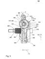
- Fig. 3 shows a partial enlargement of the centrifugal force unit 130 in the region of a centrifugal body 490.
- the first component 430 has a raceway 560 and the second component 440 has a mating track 570.
- the centrifugal force body 490 can roll along the raceway 560 with the first part body 500, ie the larger of the two rollers, while the second part body 510 is in contact with the mating track 570 and can roll along it.
- the second component 440 ie the lower part, in this case has two mutually merging bevels, which are part of the mating track 570.
- the mating track 570 has a first angle portion 580 and a subsequent portion 590 that extends at a different angle from the radial direction 420.
- the track 560 also has a section 600, which adjoins a further section 610.
- the section 600 is associated with the section 580 with respect to the contact points of the centrifugal force bodies 490 during rolling on the track 560 or the mating track 570, while the further section 610 is assigned to the further section 590 of the track 560.
- the section 600 and the further section 610 have the in Fig. 1 to 3 However, shown embodiment of a centrifugal force unit 130 no different angles. More specifically, in this region, the raceway 430 of the upper part or the first component 430 has a planar surface on which the centrifugal force body 490 can roll with the first part body 500. In contrast to this, the second component 440, that is to say the lower part, has rectangular recesses in which the mating track 570 is guided, in which the rolling or slide-supported weight 490 is guided.
- the section 580 of the mating track 570 and the section 600 of the track 560 extend in the axial direction 110 at an angle to each other.
- the section 580 of the mating track 570 and the section 600 of the track 560 approach each other with increasing distance from the axial direction 110, so run towards each other.
- These include an angle A with each other, which is typically greater than an angle B of the further portion 590 of the mating track 570 and the other portion 610 of the track 560 include each other.
- the ratio of the angle of the sections 580 and 600 to the second angle of the further sections 590, 610 is typically at least 3: 1. Frequently, in addition or alternatively, the angle between the sections 580, 600 may be at least 20 °.
- the angle between the further sections 590, 610 may typically be at most 10 °.
- a rapid increase in the distance of the first component 430 from the second component 440 can thus be achieved on the one hand at a start, ie at an increase in the rotational speed of the centrifugal force unit 130 at the beginning, while when exceeding a further limit speed when the or the centrifugal bodies 490 leave the sections 580, 600 and enter the further sections 590, 610, a further enlargement of the distance can be reduced.
- the angle A is 36 °
- the angle B is 7.5 °.
- the use of a portion and another portion of different pitches within the track 560 and mating track 570 also enables hysteresis with respect to the transmittable torque or force acting as a function of the rotational speed of the centrifugal force unit 130. Due to the different angular relationships in the sections 580, 600 compared to the further sections 590, 610, a typically higher engagement speed is thus required, in which the centrifugal body (s) 490 have moved as far along the section 580 or the section 600, the distance of the two components 430, 440 has grown such that the contact force generated along the axial direction 110 by the diaphragm spring 240 or the pressing-force-generating element 230 enables sufficient torque transmission to accelerate the motor vehicle.
- centrifugal force or the body 490 penetrated into the other section 590, 610 they are subject to a lower slope and thus downgrade force caused by the return spring elements 450 only at a lower Auskuppelitchiere to a rolling back of the centrifugal body 490 in the in Fig. 3 shown rest position causes.
- the centrifugal force unit 130 also has an outer radial stop 620 and an inner radial stop 630 with respect to the counterbore 570, which limit movement of the centrifugal body or members 490 to a maximum or a minimum distance value from the axial direction 110.
- the outer radial stop 620 which is also referred to simply as an outer stop, in this case limited in conjunction with the slope of the corresponding track 560 or mating track 570 a maximum distance value of the two components 430, 440 to each other.
- a contact pressure force which is caused by the Anpresskraftfullyden element 230, so for example the diaphragm spring 240, be limited, but it can also be a deformation of these components and thus their mechanical stress are limited.
- this may optionally limit a maximum transmittable torque, so that uncontrolled high torques can not be transmitted even at high rotational speeds of the centrifugal force unit 130 or the clutch 100.
- the inner radial stop 630 can be arranged, for example, such that it ensures that the centrifugal force body or centrifugal bodies 490 are already in contact with the sections 580, 600 of the track 560 and the mating track 570 when the centrifugal force unit 130 is at a standstill.
- a faster response of the centrifugal force unit 130 and / or an improvement in comfort can be achieved, since the centrifugal force bodies 490 are already in a defined position even when the centrifugal force unit 130 is started.
- a noise development from the clutch 100 can be reduced.
- the corresponding stops 620, 630 can also be implemented additionally or additionally in the context of the track 560. In this case, even if they are implemented as part of the mating track 570, they can be implemented as part of the first component 430 or vice versa in the case of an implementation in the context of the track 560 as part of the second component 440. It depends on which of the corresponding part body 500, 510 of the centrifugal body 490 with the respective stops 620, 630 interacts.
- the stops 620, 630 thus limit the path that the weights or centrifugal bodies 490 can travel radially outward along the oblique.
- the centrifugal body 490 thus has the first part body (outer ring), which runs against the flat surface which forms the raceway 560, and whose radial Path is limited by the stops 620 and 630.
- the centrifugal body 490 (weight) also has the second partial body 510, which is roller-mounted or slidably mounted relative to the first partial body 500, which may be, for example, an axis which projects onto the inclined or the section 580 and the further section 590 of the mating track 570 rolls off.
- Fig. 4 shows an enlarged, perspective view of a centrifugal body 490, as it is repeatedly used in the centrifugal force unit 130 shown above according to an embodiment.
- Its partial body 500 and 510 are rotatably supported by the rolling bearing 515 to each other.
- the first part of the body 500 is configured here in the form of a roller with a cylindrical jacket-shaped outer running surface 640, which is in contact with the raceway 560 of the first component 430.
- the outer race 640 extends parallel to an axial direction 650 and a circumferential direction 660 of the first body 500.
- the first partial body 500 shown here also has, in the radial direction, that is to say perpendicular to the axial direction 650 and the circumferential direction 660, a recess 670 provided on both sides of the first partial body 500, through which, for example, a surface on which the first partial body 500 optionally engages could touch second component 440, can be reduced.
- the first part body 500 also has a bore extending centrally to the axial direction 650 into which the roller bearing 515 is inserted, so that it is connected via its outer ring with the first part body.
- the rolling bearing 515 thus enables a rotational movement of the first part body 500 to the second part body 510 about the axial direction 650 around.
- rolling bearing 515 is an encapsulated needle bearing that provides a particularly compact design and provides protection against ingress of solid and liquid contaminants.
- An inner ring of the rolling bearing 515 is connected to the second part body 510.
- This is designed as a cylinder and can be considered as the axis of the first part of body 500.
- the second partial body 510 projects beyond the first partial body 500 in FIG axial direction 650, so that the second part of the body 510 can run in the region of this overhang on the mating track of the second component 440 of the centrifugal unit 130 along with this so in the region of its overhang can be in contact.
- the second part body also has an outer running surface 670 oriented parallel to the outer running surface 640 of the first part body 500 and which is in contact with the mating track 570 of the second component 440 of the centrifugal force unit 130.
- the clutch 100 or the centrifugal force unit 130 it is advisable to differentiate between different operating states. If the engine is off or is just the idling speed, causes the centrifugal force, which also acts on the centrifugal force or weights on the sections 580, 600 of the track 560 and the mating track 570, ie on the steep ramp with the angle A an axial force, which however, smaller than a force caused by the biased coil springs 460 of the return spring members 450. As a result, the first and the second component at their rest value with respect to their distance from each other, so for example, completely held each other.
- the centrifugal force unit 130 can be pressed against the diaphragm spring 240 by some of the coil springs 460 here. They act as lift-off springs here. Due to the described force relationships, however, no force is exerted on the friction pack 120 or on the clutch disc 160, so that the clutch 100 transmits no or at least no relevant torque.
- the axial force acting on the flyweights or centrifugal force body 490 overcomes the force of the coil springs 460 of the return spring elements 450.
- the first component 430 (Upper part) presses against the prestressed diaphragm spring 240 and thereby remains axially largely stationary.
- the second component 440 (lower part) moves in the direction of friction pack 120 and exerts a force that generates or transmits the torque required for starting.
- the contact pressure of the clutch 100 is also practically limited instead of an up to the maximum speed always further substantially square increasing contact pressure.
- the housing so the housing basket 140 and the rolling bearing or centrifugal body 490 can be dimensioned easier and also the maximum transmittable torque is limited to protect the drive train and its other components.
- the centrifugal force by reducing The speed of the centrifugal force unit 130 on the centrifugal force body 490 so low that it is less than the slope forces, which is caused not least by the return spring elements 450 on the shallower ramp with the angle B, which is formed by the other sections 590 and 610 , the weights can roll back from ramp B and immediately rush through the ramp with the Winkle A until they hit their inner radial stop 630.
- the slope force is generated and caused not only by the coil spring force 460 of the return spring members 450, but also by the diaphragm spring 240.
- the use of a clutch 100 with a centrifugal force unit 130 also enables a manual disengage.
- the disengaging unit 150 release mechanism
- the disengaging unit 150 can bring the hydraulic volume required for this purpose, for example via a sniffer bore of the master cylinder, out of a surge tank or into it again submit.
- the use of the sections 580, 600 and the further section 590, 610 with different angles, ie the use of kinked ramps can in this case always allow the same Ausschweg when the clutch has been accelerated once after a start on the Verrastprintiere.
- the clutch 100 according to an embodiment and / or the centrifugal force unit 130 according to one embodiment thus also allows a gear change, ie a disengagement or disconnection of the clutch.
- the disengagement force due to the use of the diaphragm spring 240 or another Anpresskraftbeskybeskybeskybesky element 230 in many cases independent of speed.
- the pressing force typically does not increase quadratically with the rotational speed, and the pressing force can be limited upwardly with respect to the achievable values. As a result, an overload of the drive train or its components can optionally be avoided.
- the Einkuppelwordiere and Auskuppelfitiere can be set differently. Also, in a clutch 100 according to an embodiment, even in sauertouriger driving a slipping same can be avoided.
- the clutch 100 thus provides a centrifugal clutch with a third-party option and a Anpresskraftbegrenzung that can relieve the driver of a motor vehicle by an automatic coupling without having to resort to an electromechanical actuator.
- the coupling 100 was previously described exclusively in connection with the diaphragm spring 240, other types of spring can also be used within the scope of exemplary embodiments of a clutch 100.
- the diaphragm spring 240 can be exchanged for a diaphragm spring.
- Other pressing-force generating elements 230 for example based on one or more coil springs, gas springs or other pneumatic or elastic spring elements can be used here.
- an additional mechanical implementation of a force reduction or interruption may be necessary or advisable here.
- the return spring elements 450 can be implemented for example on the basis of tension springs, disc springs or other pneumatic or elastic spring elements.
Landscapes
- Engineering & Computer Science (AREA)
- General Engineering & Computer Science (AREA)
- Mechanical Engineering (AREA)
- One-Way And Automatic Clutches, And Combinations Of Different Clutches (AREA)
Priority Applications (2)
| Application Number | Priority Date | Filing Date | Title |
|---|---|---|---|
| EP11188942.4A EP2592297A1 (fr) | 2011-11-14 | 2011-11-14 | Unité de force centrifuge et couplage |
| US13/676,835 US20130118857A1 (en) | 2011-11-14 | 2012-11-14 | Centrifugal unit and clutch |
Applications Claiming Priority (1)
| Application Number | Priority Date | Filing Date | Title |
|---|---|---|---|
| EP11188942.4A EP2592297A1 (fr) | 2011-11-14 | 2011-11-14 | Unité de force centrifuge et couplage |
Publications (1)
| Publication Number | Publication Date |
|---|---|
| EP2592297A1 true EP2592297A1 (fr) | 2013-05-15 |
Family
ID=45217200
Family Applications (1)
| Application Number | Title | Priority Date | Filing Date |
|---|---|---|---|
| EP11188942.4A Withdrawn EP2592297A1 (fr) | 2011-11-14 | 2011-11-14 | Unité de force centrifuge et couplage |
Country Status (2)
| Country | Link |
|---|---|
| US (1) | US20130118857A1 (fr) |
| EP (1) | EP2592297A1 (fr) |
Families Citing this family (1)
| Publication number | Priority date | Publication date | Assignee | Title |
|---|---|---|---|---|
| KR101655642B1 (ko) * | 2015-01-05 | 2016-09-07 | 현대자동차주식회사 | 하이브리드 차량용 엔진클러치의 키스포인트 학습 방법 |
Citations (4)
| Publication number | Priority date | Publication date | Assignee | Title |
|---|---|---|---|---|
| US2018101A (en) * | 1933-01-23 | 1935-10-22 | Borg Warner | Automatic clutch |
| DE102004030280A1 (de) | 2003-06-30 | 2005-01-20 | Zf Sachs Ag | Fliehkraftkupplung |
| EP2009310A2 (fr) * | 2007-06-29 | 2008-12-31 | Yamaha Hatsudoki Kabushiki Kaisha | Embrayage |
| EP2175155A2 (fr) * | 2008-10-10 | 2010-04-14 | Yamaha Hatsudoki Kabushiki Kaisha | Embrayage à friction avec masses centrifuges |
Family Cites Families (3)
| Publication number | Priority date | Publication date | Assignee | Title |
|---|---|---|---|---|
| US7014026B2 (en) * | 2001-06-07 | 2006-03-21 | Drussel Wilfley Design, L.L.C. | Manual/automatic pressure control mechanism for centrifugal clutch |
| US7306084B2 (en) * | 2003-12-23 | 2007-12-11 | Zf Meritor, Llc | Dynamic modification of centrifugal clutch |
| US7137498B2 (en) * | 2004-03-11 | 2006-11-21 | Eaton Corporation | Centrifugal clutch with improved wear life and disengagement characteristics |
-
2011
- 2011-11-14 EP EP11188942.4A patent/EP2592297A1/fr not_active Withdrawn
-
2012
- 2012-11-14 US US13/676,835 patent/US20130118857A1/en not_active Abandoned
Patent Citations (4)
| Publication number | Priority date | Publication date | Assignee | Title |
|---|---|---|---|---|
| US2018101A (en) * | 1933-01-23 | 1935-10-22 | Borg Warner | Automatic clutch |
| DE102004030280A1 (de) | 2003-06-30 | 2005-01-20 | Zf Sachs Ag | Fliehkraftkupplung |
| EP2009310A2 (fr) * | 2007-06-29 | 2008-12-31 | Yamaha Hatsudoki Kabushiki Kaisha | Embrayage |
| EP2175155A2 (fr) * | 2008-10-10 | 2010-04-14 | Yamaha Hatsudoki Kabushiki Kaisha | Embrayage à friction avec masses centrifuges |
Also Published As
| Publication number | Publication date |
|---|---|
| US20130118857A1 (en) | 2013-05-16 |
Similar Documents
| Publication | Publication Date | Title |
|---|---|---|
| EP2153080B1 (fr) | Dispositif d'embrayage double avec element de guidage de piston | |
| DE69717174T2 (de) | Vorrichtung für die Bewegungsbegrenzung einer Multilamellen- Reibungskupplung | |
| EP3069035B1 (fr) | Embrayage à friction | |
| DE102022114761B3 (de) | Trockene Doppelkupplung mit individuell betätigbaren Teilkupplungen | |
| WO2015135540A1 (fr) | Embrayage à friction à commande centrifuge | |
| EP2494224B1 (fr) | Embrayage comprenant un pré-embrayage et un embrayage principal | |
| WO2015144157A1 (fr) | Système à double embrayage et cylindre récepteur concentrique (csc) avec montage sur palier axial comportant un talon pour recevoir le csc et chaîne de transmission | |
| WO2018054412A1 (fr) | Système d'actionnement et dispositif embrayage pour un véhicule automobile | |
| EP2123929B1 (fr) | Agencement d'accouplement, notamment destiné à l'accouplement rotatif sélectif d'un arbre d'entrée d'un compresseur dans un véhicule doté d'un organe d'entraînement | |
| WO2011050775A1 (fr) | Embrayage humide | |
| EP3224494B1 (fr) | Système d'embrayage | |
| DE102014218548B3 (de) | Kupplung für einen Antriebsstrang eines Kraftfahrzeugs | |
| DE112011103535T5 (de) | Kuplungsvorrichtung | |
| EP3286446B1 (fr) | Système d'embrayage | |
| DE102011086009A1 (de) | Selbstnachstellende Kupplung | |
| DE112011101258B4 (de) | Kupplungsvorrichtung | |
| DE102021114158A1 (de) | Elektromotor zum elektrischen Antrieb eines Kraftfahrzeugs | |
| DE10018646B4 (de) | Doppelkupplungsanordnung | |
| EP2592297A1 (fr) | Unité de force centrifuge et couplage | |
| EP1862688A2 (fr) | Agencement de transmission d'un couple de rotation pour le conducteur de commande d'un véhicule | |
| DE102010042639B4 (de) | Kupplungsmechanismus mit Ausgleichsgewicht | |
| EP1521005A2 (fr) | Unité d'embrayage et/ou de frein | |
| DE102014217279B4 (de) | Doppelkupplung | |
| EP2041444B1 (fr) | Embrayage à huile hydraulique | |
| EP2245324B1 (fr) | Embrayage de démarrage, en particulier pour véhicules de course et de sport |
Legal Events
| Date | Code | Title | Description |
|---|---|---|---|
| PUAI | Public reference made under article 153(3) epc to a published international application that has entered the european phase |
Free format text: ORIGINAL CODE: 0009012 |
|
| AK | Designated contracting states |
Kind code of ref document: A1 Designated state(s): AL AT BE BG CH CY CZ DE DK EE ES FI FR GB GR HR HU IE IS IT LI LT LU LV MC MK MT NL NO PL PT RO RS SE SI SK SM TR |
|
| AX | Request for extension of the european patent |
Extension state: BA ME |
|
| 17P | Request for examination filed |
Effective date: 20131114 |
|
| GRAP | Despatch of communication of intention to grant a patent |
Free format text: ORIGINAL CODE: EPIDOSNIGR1 |
|
| INTG | Intention to grant announced |
Effective date: 20140218 |
|
| STAA | Information on the status of an ep patent application or granted ep patent |
Free format text: STATUS: THE APPLICATION IS DEEMED TO BE WITHDRAWN |
|
| 18D | Application deemed to be withdrawn |
Effective date: 20140701 |