EP2597321A1 - Magnetischer Entkupplungsmechanismus für aneinander zu reihende leistenförmige Profile sowie Leisten mit einem derartigen Entkupplungsmechanismus - Google Patents
Magnetischer Entkupplungsmechanismus für aneinander zu reihende leistenförmige Profile sowie Leisten mit einem derartigen Entkupplungsmechanismus Download PDFInfo
- Publication number
- EP2597321A1 EP2597321A1 EP12007843.1A EP12007843A EP2597321A1 EP 2597321 A1 EP2597321 A1 EP 2597321A1 EP 12007843 A EP12007843 A EP 12007843A EP 2597321 A1 EP2597321 A1 EP 2597321A1
- Authority
- EP
- European Patent Office
- Prior art keywords
- strip
- sword
- profile
- decoupling mechanism
- mechanism according
- Prior art date
- Legal status (The legal status is an assumption and is not a legal conclusion. Google has not performed a legal analysis and makes no representation as to the accuracy of the status listed.)
- Granted
Links
- 230000007246 mechanism Effects 0.000 title claims abstract description 23
- 230000005415 magnetization Effects 0.000 claims abstract description 9
- 238000005286 illumination Methods 0.000 claims description 4
- 238000003780 insertion Methods 0.000 claims description 4
- 230000037431 insertion Effects 0.000 claims description 4
- 230000009471 action Effects 0.000 claims description 2
- 230000008878 coupling Effects 0.000 description 4
- 238000010168 coupling process Methods 0.000 description 4
- 238000005859 coupling reaction Methods 0.000 description 4
- 230000008901 benefit Effects 0.000 description 3
- 230000000694 effects Effects 0.000 description 3
- 238000005192 partition Methods 0.000 description 3
- 229910001220 stainless steel Inorganic materials 0.000 description 3
- 239000010935 stainless steel Substances 0.000 description 3
- 229910001369 Brass Inorganic materials 0.000 description 2
- XAGFODPZIPBFFR-UHFFFAOYSA-N aluminium Chemical compound [Al] XAGFODPZIPBFFR-UHFFFAOYSA-N 0.000 description 2
- 229910052782 aluminium Inorganic materials 0.000 description 2
- 239000010951 brass Substances 0.000 description 2
- 238000011161 development Methods 0.000 description 2
- 230000018109 developmental process Effects 0.000 description 2
- 239000000696 magnetic material Substances 0.000 description 2
- 238000004026 adhesive bonding Methods 0.000 description 1
- 230000004323 axial length Effects 0.000 description 1
- 230000015572 biosynthetic process Effects 0.000 description 1
- 238000005516 engineering process Methods 0.000 description 1
- 238000004519 manufacturing process Methods 0.000 description 1
- 239000000463 material Substances 0.000 description 1
- 230000007935 neutral effect Effects 0.000 description 1
- 230000035699 permeability Effects 0.000 description 1
- 239000007787 solid Substances 0.000 description 1
Images



Classifications
-
- F—MECHANICAL ENGINEERING; LIGHTING; HEATING; WEAPONS; BLASTING
- F16—ENGINEERING ELEMENTS AND UNITS; GENERAL MEASURES FOR PRODUCING AND MAINTAINING EFFECTIVE FUNCTIONING OF MACHINES OR INSTALLATIONS; THERMAL INSULATION IN GENERAL
- F16B—DEVICES FOR FASTENING OR SECURING CONSTRUCTIONAL ELEMENTS OR MACHINE PARTS TOGETHER, e.g. NAILS, BOLTS, CIRCLIPS, CLAMPS, CLIPS OR WEDGES; JOINTS OR JOINTING
- F16B7/00—Connections of rods or tubes, e.g. of non-circular section, mutually, including resilient connections
- F16B7/04—Clamping or clipping connections
- F16B7/0406—Clamping or clipping connections for rods or tubes being coaxial
- F16B7/0413—Clamping or clipping connections for rods or tubes being coaxial for tubes using the innerside thereof
- F16B7/042—Clamping or clipping connections for rods or tubes being coaxial for tubes using the innerside thereof with a locking element, e.g. pin, ball or pushbutton, engaging in a hole in the wall of at least one tube
-
- F—MECHANICAL ENGINEERING; LIGHTING; HEATING; WEAPONS; BLASTING
- F21—LIGHTING
- F21S—NON-PORTABLE LIGHTING DEVICES; SYSTEMS THEREOF; VEHICLE LIGHTING DEVICES SPECIALLY ADAPTED FOR VEHICLE EXTERIORS
- F21S4/00—Lighting devices or systems using a string or strip of light sources
- F21S4/20—Lighting devices or systems using a string or strip of light sources with light sources held by or within elongate supports
- F21S4/28—Lighting devices or systems using a string or strip of light sources with light sources held by or within elongate supports rigid, e.g. LED bars
-
- F—MECHANICAL ENGINEERING; LIGHTING; HEATING; WEAPONS; BLASTING
- F16—ENGINEERING ELEMENTS AND UNITS; GENERAL MEASURES FOR PRODUCING AND MAINTAINING EFFECTIVE FUNCTIONING OF MACHINES OR INSTALLATIONS; THERMAL INSULATION IN GENERAL
- F16B—DEVICES FOR FASTENING OR SECURING CONSTRUCTIONAL ELEMENTS OR MACHINE PARTS TOGETHER, e.g. NAILS, BOLTS, CIRCLIPS, CLAMPS, CLIPS OR WEDGES; JOINTS OR JOINTING
- F16B2200/00—Constructional details of connections not covered for in other groups of this subclass
- F16B2200/83—Use of a magnetic material
-
- F—MECHANICAL ENGINEERING; LIGHTING; HEATING; WEAPONS; BLASTING
- F16—ENGINEERING ELEMENTS AND UNITS; GENERAL MEASURES FOR PRODUCING AND MAINTAINING EFFECTIVE FUNCTIONING OF MACHINES OR INSTALLATIONS; THERMAL INSULATION IN GENERAL
- F16B—DEVICES FOR FASTENING OR SECURING CONSTRUCTIONAL ELEMENTS OR MACHINE PARTS TOGETHER, e.g. NAILS, BOLTS, CIRCLIPS, CLAMPS, CLIPS OR WEDGES; JOINTS OR JOINTING
- F16B7/00—Connections of rods or tubes, e.g. of non-circular section, mutually, including resilient connections
- F16B7/22—Connections of rods or tubes, e.g. of non-circular section, mutually, including resilient connections using hooks or like elements
-
- F—MECHANICAL ENGINEERING; LIGHTING; HEATING; WEAPONS; BLASTING
- F21—LIGHTING
- F21V—FUNCTIONAL FEATURES OR DETAILS OF LIGHTING DEVICES OR SYSTEMS THEREOF; STRUCTURAL COMBINATIONS OF LIGHTING DEVICES WITH OTHER ARTICLES, NOT OTHERWISE PROVIDED FOR
- F21V21/00—Supporting, suspending, or attaching arrangements for lighting devices; Hand grips
- F21V21/005—Supporting, suspending, or attaching arrangements for lighting devices; Hand grips for several lighting devices in an end-to-end arrangement, i.e. light tracks
-
- F—MECHANICAL ENGINEERING; LIGHTING; HEATING; WEAPONS; BLASTING
- F21—LIGHTING
- F21Y—INDEXING SCHEME ASSOCIATED WITH SUBCLASSES F21K, F21L, F21S and F21V, RELATING TO THE FORM OR THE KIND OF THE LIGHT SOURCES OR OF THE COLOUR OF THE LIGHT EMITTED
- F21Y2103/00—Elongate light sources, e.g. fluorescent tubes
- F21Y2103/10—Elongate light sources, e.g. fluorescent tubes comprising a linear array of point-like light-generating elements
-
- F—MECHANICAL ENGINEERING; LIGHTING; HEATING; WEAPONS; BLASTING
- F21—LIGHTING
- F21Y—INDEXING SCHEME ASSOCIATED WITH SUBCLASSES F21K, F21L, F21S and F21V, RELATING TO THE FORM OR THE KIND OF THE LIGHT SOURCES OR OF THE COLOUR OF THE LIGHT EMITTED
- F21Y2115/00—Light-generating elements of semiconductor light sources
- F21Y2115/10—Light-emitting diodes [LED]
Definitions
- the invention relates to a magnetic Entkupplungsmechanismus for mutually to be joined strip-shaped profile, comprising a first formed from a profile strip and a second formed of a profile bar, wherein the first and the second bar are releasably connected to each other by a positive connection.
- a special field of application are light strips, which are between 10 cm and 300 cm long and in the profile at regular intervals to each other lighting units, in particular light-emitting diodes included.
- an electrical interface necessary to energize the lighting units of the subsequent bar or strips.
- LED light strips are gaining increasing attention especially for applications in advertising and at events such as trade fairs or concerts.
- the light strips are not only strung together to obtain the desired length, but in addition a plurality of light strips arranged side by side, so that a banner, a curtain or other lighting surface, e.g. Above a booth or on a stage is created, which allows a video presentation on the resulting overall structure of LED light strips. Since each lighting unit can be controlled individually, with such banners or curtains large advertising and information carrier can be formed, the letters, words or symbols display or just spectacular lighting effects can produce.
- a permanent connection for example, a non-releasable positive connection, therefore separates as well as a screw, since their release is too time and labor consuming.
- An adhesion is also too difficult to solve, provided that it meets the required safety requirements.
- a magnetic uncoupling mechanism for strip-shaped profiles to be joined, comprising a first strip formed from a profile and a second strip formed from a profile, wherein the first and the second strip are releasably connectable to each other by means of a positive connection and the positive connection by a movable permanent magnet locking means can be produced, the magnetization is in the direction of its mobility, wherein the positive connection by means of an external Entkupplungsmagneten is solvable.
- a particular advantage of this solution is that the uncoupling mechanism is not visible from the outside. This has, on the one hand, aesthetic advantages, because, apart from the dividing plane formed by the end faces, the strips merge into one another at their connecting points without optically recognizable locking elements. On the other hand, it is ensured that the strips can only be detached from one another with the special knowledge of the uncoupling mechanism. This is a security feature and theft protection.
- the magnetic Entkupplungsmechanismus forms a device or a bar system comprising the first and the second profile-shaped bar, which are releasably connected to one another by means of the positive connection of the invention. Due to the Entkupplungsmechanismusses invention, it is easily possible to solve a connection of two strips by positive locking again and to separate the two strips from each other. For this purpose, a commercially available permanent magnet can be used, which is to be held in the region of the positive connection to the corresponding bar. Depending on the configuration of the positive connection, ie depending on the direction in which the locking means engages to form the positive connection, the polarity of the Entkupplungsmagneten is to be selected so that the magnetic locking means repelled or used by the Entkupplungsmagneten. The Locking of the two strips is only due to the positive connection. A frictional connection by the magnetic force of the locking means is not required. The locking means itself provides only because of its positive connection with another element of the other profile for the locking of the two strips.
- the first bar at one axial end of a protruding sword and the second bar on a receptacle for insertion of the sword.
- the sword is tongue-shaped and stabilizes the joint between the two strips by protruding into both profiles.
- the sword may have a recess and the second bar a spring element which carries the locking means, wherein the locking means rests in the inserted into the receptacle state of the sword forming the positive locking in its recess rests.
- a depression in this sense is any form the locking means receiving, in particular a recess, a bore or a recess.
- the locking means must be pushed out of the recess. This can be done by rectified rectified magnetic force of Entkupplungsmagneten because repel magnetically rectified poles. If the spring element viewed from the outside of the profile of the second bar, arranged in front of the sword, the locking means must be pulled out of the recess. This can be done by the locking means opposing magnetic force of Entkupplungsmagneten, as attract magnetically oppositely directed poles. In both cases, the locking means is moved against the restoring force of the spring element.
- the sword may carry the locking means and the second bar having a recess, wherein the locking means in the inserted into the receptacle state of the sword forming the positive fit in the recess the second bar latching rests.
- the locking means may be held on the sword and pressed with a spring away from it, so that the latching means can be pressed spring loaded into the recess of the second strip or pressed in the assembled state.
- the locking means may form part of the sword, wherein the sword is then even resilient.
- the spring element may be a leaf spring which is held at one end to the profile of the second strip and carries at its opposite, resilient end the locking means.
- the spring element may also be a spiral spring which carries the latching means at an axial end. In this case, however, the locking means is to be guided on the profile of the second bar, so that it can not fall out when the sword is removed.
- the latching means can move in an opening of the profile movable, so that a tensile force of the profile does not transfer to the attachment of the leaf spring, but is absorbed by the profile.
- the locking means can tilt in the opening when the spring element is a leaf spring held on one side. Because in this case, the movement of the locking means extends along an arc section.
- the spring element may be formed by a strip-shaped web, which is resiliently supported on both sides of the profile and approximately centrally carries the locking means. Such a web then has a largely linear movement, so that it can not lead to tilting of the locking means in the opening.
- the web can be formed by a thin sheet or plastic plate. Its longitudinal extent can run parallel to the profile. For example, can cross extend to the profile on both sides of the web in each case a bracket on which the web is supported by means of springs.
- the sword may have a bevel on its front facing the second bar front, so that it can be better inserted into the receptacle of the other bar.
- the bevel also causes the locking means is raised, slides along the slope along and snaps with a fully inserted sword in the recess detent.
- the locking means may also have a chamfer on its side directed to the first strip, so that it is lifted when the sword is inserted.
- At least the profile of the second ledge is made of a non-magnetic material, such as aluminum, i. a material of high magnetic permeability without the magnetic field amplifying effect, so that the magnetic field of Entkupplungsmagneten freely pass through the profile and can act on the locking means.
- a non-magnetic material such as aluminum, i. a material of high magnetic permeability without the magnetic field amplifying effect, so that the magnetic field of Entkupplungsmagneten freely pass through the profile and can act on the locking means.
- the sword and / or the spring element made of a non-magnetic material of the type mentioned, so that the magnetic field of Entkupplungsmagneten freely pass through the sword or the spring element and can act on the locking means.
- the sword and / or spring element may be made of stainless steel or brass.
- the locking means may be a locking bolt, ie a cylindrical, solid body, wherein the cross section of the cylinder may be arbitrary, in particular round, oval or even rectangular.
- the recess of the sword is then formed corresponding to its shape and dimension, so that the locking pin can eino in this form-fitting manner.
- the strip-shaped profile of the first and second bar preferably has a closed profile space in which the sword is firmly inserted and thus held.
- the closed profile space extends at least along one part, preferably along the entire axial length of the profile.
- the inner cross section of the profile space corresponds approximately to the outer cross section of the sword, so that the sword rests positively in the profile space, where it can be glued or screwed there. Alternatively, it can also be pressed non-positively into the profile space.
- the recording of the profile of the second bar may be formed by a closed profile space in which the sword is inserted.
- the inner cross section of the profile space of the second strip should be slightly larger than the outer cross section of the sword, so that the sword is indeed form-fitting, however, without effort in the profile space can be inserted.
- the two profiles can be U-shaped. They thus have in their length a high stability in terms of their resilience. Incidentally, they form a profile space which is open only on one side and has only one open longitudinal side, to which - in the case of the use of the profiles for light strips - the illumination means can have their main emission direction. Due to the sides of the open profile space limb, the U-profile can be well shed to protect the lighting.
- the spring element in particular the leaf spring, may be fastened to a wall bounding the closed profile space of the second strip, wherein the latching means projects into the closed profile space.
- the wall having an opening, in particular a bore, through which the latching means extends movably into the profile space.
- the engagement of the locking means in the opening prevents pulling on the first bar tearing off the spring element. Because by pulling the bar, pulls the sword, in the recess rests the locking means, according to the locking means. would the locking means be free, the tensile force would be transferred to the attachment of the leaf spring and solve this if necessary.
- the opening in the pulling direction limiting profile wall limits the transverse mobility of the locking means and absorbs the tensile force, so that the risk of tearing of the leaf spring is prevented.
- the closed profile space may preferably lie below the open profile space.
- the wall to which the spring element is attached the partition wall between the upper, open profile space and the lower, closed profile space.
- a strip with a part of the above-described magnetic Entkupplungsmechanismusses is proposed, which is formed from a profile and releasably connectable by means of a positive connection with another bar, the positive connection is produced by a movable permanent magnetic latching means whose magnetization is in the direction of its mobility, wherein the positive connection by means of an external Entkupplungsmagneten is solvable.
- the bar at an axial end face on a projecting sword which is inserted into a receptacle of the other bar and having a recess into which inserted into the receptacle state of the sword, a movable permanent magnetic locking means can form the locking form eino locking.
- the strip may have a receptacle for inserting a projecting from an axial end face of the other bar sword and a spring element which carries a permanent magnetic locking means which rests locking in the inserted state in a recess of the sword in a recess of the sword locking, wherein the magnetization of Locking means is directed in spring action direction of the spring element and the lock by means of an external decoupling magnet rectified magnetic force is releasable.
- the above-described, uncoupling mechanism according to the invention can be used in particular in light strips, are arranged in the illumination means, in particular a plurality of light-emitting diodes, along the longitudinal extent of their profile in this.
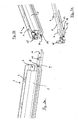
- FIG. 1 shows a first of a profile 5 formed bar 1 and a second of an identical profile 5 formed bar 2, which are releasably connected to each other by a positive connection.
- the profiles 5 abut with their front ends a parting plane 3 forming flush with each other.
- the coupling mechanism or uncoupling mechanism is not visible.
- the two strips 1, 2 form light strips in whose profiles 5 a plurality of illumination means 4 in the form of light emitting diodes 4 are arranged equidistantly from each other at a distance from each other.
- the light-emitting diodes 4 are mounted on a carrier board 6, in particular soldered, of which in each case one rests in each profile 5, in particular held there.
- the first bar 1 has at an axial end face a protruding tongue-shaped sword 9.
- the sword 9 is shown transparent in this illustration. It is partially, ie about half, in a closed profile space 8, in which it is fixed, for example glued or clamped by external force on the profile 5.
- the sword 9 has a recess 11 in the form of a circular cylindrical bore for receiving a locking means 13. It has at its protruding end top side a bevel 10 to raise the locking means 13 when connecting the first with the second bar 2.
- FIG. 2b It has a receptacle 8, 19 for insertion of the sword 9 of the first strip 1.
- the receptacle 8, 19 is formed by the closed profile space 8 of the profile 5, which at the end face of the axial end of the profile 5 a Opening 19, through which the sword 9 is inserted into the closed profile space 8.
- Electrical sockets 15 for energizing the carrier board 6 respectively of the LEDs 4 and to connect to corresponding pins of the first bar 1 are also in FIG. 2b shown.
- the second bar 2 is shown without its profile 5. It has a latching means 13, which is arranged on a resilient end 17 of a spring element 12 on its underside 14. As a result, the locking means 13 is movable.
- the latching means 13 is designed as a locking bolt, which in the inserted into the receptacle 8, 19 state of the sword 9 form a positive fit 11, 13 rests latching in the recess 11 of the sword.
- the spring element 12 is designed as a leaf spring. The other end 18 of the spring element 12 is not on the attached profile 5 attached.
- Figure 2c shows the spring element 12 in its neutral position. If the sword 9 is inserted into the receptacle 8, 19, the bevel 10 raises the locking means 13 against the spring force of the spring element 12 until it slips into the recess 11. The two strips 1, 2 are then locked. This is in Fig. 3 shown.
- the latching means 13 is designed to be permanently magnetic, the magnetization of the latching means 13 being in the direction of its mobility. This means that one magnetic pole lies on the side facing the board 6 and the other pole lies on the side facing the sword 9.
- an external permanent magnetic Entkupplungsmagneten 16 this positive connection can be solved by the pole of the Entkupplungsmagneten 16 is brought into the magnetic field of the locking means 13, which corresponds to its polarity the pole of the locking means 13, which is directed to the sword 9.
- the latching means 13 Since rectified poles repel each other, the latching means 13 is pushed out of the recess 11 against the force of the spring element 12 and thus releases the sword 9. This is in FIG. 4 shown.
- the first bar 1 can now be pulled out with its sword 9 from the receptacle 8, 19 of the second bar 2.
- the magnetic field of the external Entkupplungsmagneten 16 can freely penetrate the locking means 13 and thus the locking means does not adhere magnetically to the sword 9, the sword 9 is made of stainless steel or brass.
- the leaf spring 12 is made of stainless steel.
- FIG. 5 A cross section of the profile 5 of the second strip is in FIG. 5 shown.
- the profile 5 is U-shaped and made of aluminum, so that it is not magnetic.
- the profile width is about 9mm, but other profile widths between 5 and 20 mm can be used.
- It has a profile space 7 which is open on one longitudinal side and the underlying, closed profile space 8. It can be seen that the inner cross-section of the closed profile space 8 is slightly larger than the one outer cross-section of the sword 9. Concerning the shape, both the cross section of the closed profile space 8 and the cross section of the sword 9 are rectangular.
- the open 7 and the closed 8 profile space are separated by a partition 20, in which an opening 21 is provided.
- the locking means 13 extends into the closed profile space movable into it, where it is as in Fig. 5 shown extends approximately halfway into the recess 11 in the sword 9.
- the spring element 12 rests on the side facing the open profile space 7 side of the partition wall 20. It is also attached to this page.
- the engagement of the latching means 13 in the opening 21 prevents pulling on the first strip 1, the spring element 12 breaks off.
- the leaf spring has a length of about 3cm and a width of about 5mm. Its thickness is less than 1 mm, especially at 0.5mm.
- the sword has a length of 2cm, a width of 5mm a thickness of 2mm.
- each bar 1, 2 each comprise a part of the magnetic Entkupplungsmechanismusses invention, are formed from a profile 5 and releasably connectable by means of a positive connection 11, 13 with the respective other bar 2, 1, wherein the positive connection 11, 13 by the movable, permanent magnetic latching means 13 can be produced, the magnetization is in the direction of its mobility, and wherein the positive connection 11, 13 by means of an external Entkupplungsmagneten 16 is solvable.
Landscapes
- Engineering & Computer Science (AREA)
- General Engineering & Computer Science (AREA)
- Mechanical Engineering (AREA)
- Toys (AREA)
- Non-Portable Lighting Devices Or Systems Thereof (AREA)
Abstract
Description
- Die Erfindung betrifft einen magnetischen Entkupplungsmechanismus für aneinander zu reihende leistenförmige Profile, umfassend eine erste aus einem Profil gebildete Leiste und eine zweite aus einem Profil gebildete Leiste, wobei die erste und die zweite Leiste mittels eines Formschlusses miteinander lösbar verbindbar sind.
- In vielen Bereichen ist es erforderlich, leistenförmige Profile aneinander zu reihen, um auf diese Art ein einziges, verlängertes Profil, d.h. eine einzige Leiste zu erhalten. Die Profile werden jeweils an ihren axialen Enden stirnseitig aneinander gesetzt. Dabei ist es bekannt, die Profile miteinander untrennbar zu verbinden, z.B. durch Verkleben oder lösbar zu verbinden, beispielsweise zu verschrauben. Es ist jedoch auch bekannt, die Profile kraftschlüssig mittels Presspassung zu verbinden, wobei ein von dem einen Profil abstehendes Element in eine Aufnahme des anderen Profils kraftschlüssig eingepresst wird. Auch bekannt ist es, mittels Formschluss zwischen einem rastenden Element des einen Profils und einer das rastende Element aufnehmenden Ausformung des anderen Profils diese Profile fest zu verriegeln.
- Ein besonderer Anwendungsbereich sind Lichtleisten, die zwischen 10 cm und 300 cm lang sind und in dem Profil in regelmäßigem Abstand zu einander Beleuchtungseinheiten, insbesondere Leuchtdioden, enthalten. Neben der mechanischen Schnittstelle zwischen zwei Lichtleisten respektive deren Profilen, ist dann zusätzlich eine elektrische Schnittstelle nötig, um die Beleuchtungseinheiten der nachfolgenden Leiste oder Leisten zu bestromen.
- LED-Lichtleisten gewinnen insbesondere für Anwendungen in der Werbung und bei Veranstaltungen wie Messen oder Konzerten zunehmend an Beachtung. Dabei werden die Lichtleisten nicht lediglich an einander gereiht, um die gewünschte Länge zu erhalten, sondern zusätzlich mehrere Lichtleisten nebeneinander angeordnet, so dass ein Banner, ein Vorhang oder eine sonstige Leuchtfläche, z.B. über einem Messestand oder auf einer Bühne entsteht, die ein Videodarstellung auf der so entstehenden Gesamtstruktur von LED-Lichtleisten ermöglicht. Da jede Beleuchtungseinheit einzeln angesteuert werden kann, sind mit derartigen Bannern oder Vorhängen große Werbungs- und Informationsträger bildbar, die Buchstaben, Worte oder Symbole anzeigen oder einfach nur beeindruckende Lichteffekte erzeugen können.
- Für zeitweise stattfindende Veranstaltungen wie Messen oder Konzerte müssen die Lichtleisten zusammen- und wieder auseinandergebaut werden, wobei es aus Sicherheitsgründen von besonderer Wichtigkeit ist, dass die Lichtleisten einerseits besonders gut verriegelt sind und sich andererseits auf einfache Weise wieder lösen lassen. Eine dauerhafte Verbindung, beispielsweise ein unlösbarer Formschluss, scheidet daher ebenso aus, wie eine Verschraubung, da ihr Lösen zu zeit- und arbeitsaufwändig ist. Ein Kraftschluss ist ebenfalls zu schwierig zu lösen, sofern er den gebotenen Sicherheitsanforderungen genügen soll.
- Es ist daher Aufgabe der vorliegenden Erfindung, eine Verbindungstechnik für leistenförmige Profile, insbesondere für Lichtleisten zu schaffen, die zum Einen eine sichere Verbindung zweier Leisten gewährleistet, andererseits auf einfache und schnelle Art und Weise lösbar ist.
- Erfindungsgemäß wird diese Aufgabe gemäß Anspruch 1 durch einen Formschluss zwischen den beiden Profilen der Leisten mit einem magnetischen Entkupplungsmechanismus gelöst. Vorteilhafte Weiterbildungen sind in den Unteransprüchen angegeben.
- Erfindungsgemäß wird ein magnetischer Entkupplungsmechanismus für aneinander zu reihende leistenförmige Profile vorgeschlagen, umfassend eine erste aus einem Profil gebildete Leiste und eine zweite aus einem Profil gebildete Leiste, wobei die erste und die zweite Leiste mittels eines Formschlusses miteinander lösbar verbindbar sind und der Formschluss durch ein bewegliches permanentmagnetisches Rastmittel herstellbar ist, dessen Magnetisierung in Richtung seiner Bewegbarkeit liegt, wobei der Formschluss mittels eines externen Entkupplungsmagneten lösbar ist.
- Ein besonderer Vorteil dieser Lösung ist, dass der Entkupplungsmechanismus von außen nicht sichtbar ist. Dies hat zum einen ästhetische Vorteile, weil die Leisten an ihren Verbindungsstellen abgesehen von der durch die Stirnseiten gebildeten Trennebene ohne optisch erkennbare Verriegelungselemente ineinander übergehen. Zum anderen ist gewährleistet, dass die Leisten nur mit der Spezialkenntnis über den Entkupplungsmechanismus voneinander gelöst werden können. Dies ist ein Sicherheitsmerkmal und ein Diebstahlschutz.
- Der magnetische Entkupplungsmechanismus bildet eine Vorrichtung oder ein Leistensystem umfassend die erste und die zweite profilförmige Leiste, die mittels des erfindungsgemäßen Formschlusses miteinander lösbar verbindbar sind. Aufgrund des erfindungsgemäßen Entkupplungsmechanismusses ist es auf einfache Weise möglich, eine Verbindung zweier Leisten durch Formschluss wieder zu lösen und die beiden Leisten voneinander zu trennen. Hierfür kann ein Handelsüblicher Permanentmagnet dienen, der im Bereich des Formschlusses an die entsprechende Leiste zu halten ist. Je nach Ausgestaltung des Formschlusses, d.h. je nachdem in welche Richtung das Rastmittel zur Bildung des Formschlusses einrastet, ist die Polung des Entkupplungsmagneten so zu wählen, das das magnetische Rastmittel von dem Entkupplungsmagneten abgestoßen oder herangezogen wird. Die Verriegelung der beiden Leisten erfolgt nur aufgrund des Formschlusses. Einer kraftschlüssigen Verbindung durch die Magnetkraft des Rastmittels bedarf es nicht. Das Rastmittel selbst sorgt lediglich aufgrund seines Formschlusses mit einem anderen Element des anderen Profils für die Verriegelung der beiden Leisten.
- Vorzugsweise weist die erste Leiste an einem axialen Stirnende ein abstehendes Schwert und die zweite Leiste eine Aufnahme zum Einschieben des Schwerts auf. Das Schwert ist zungenförmig und stabilisiert die Verbindungsstelle zwischen den beiden Leisten, indem es in beide Profile hineinragt.
- Bei einer ersten Ausführungsvariante kann das Schwert eine Vertiefung und die zweite Leiste ein Federelement aufweisen, das das Rastmittel trägt, wobei das Rastmittel im in die Aufnahme eingeschobenen Zustand des Schwerts den Formschluss bildend in seiner Vertiefung verriegelnd einliegt. Eine Vertiefung in diesem Sinne ist jede das Rastmittel aufnehmende Form, insbesondere auch eine Ausnehmung, eine Bohrung oder ein Rücksprung.
- Ist das Federelement von der Außenseite des Profils der zweiten Leiste betrachtet, hinter dem Schwert angeordnet, muss das Rastmittel aus der Vertiefung herausgedrückt werden. Dies kann durch zum Rastmittel gleichgerichtete Magnetkraft des Entkupplungsmagneten erfolgen, da sich magnetisch gleichgerichtete Pole abstoßen. Ist das Federelement von der Außenseite des Profils der zweiten Leiste betrachtet, vor dem Schwert angeordnet, muss das Rastmittel aus der Vertiefung herausgezogen werden. Dies kann durch zum Rastmittel entgegen gerichtete Magnetkraft des Entkupplungsmagneten erfolgen, da sich magnetisch entgegen gerichtete Pole anziehen. In beiden Fällen wird das Rastmittel entgegen der Rückstellkraft des Federelements bewegt.
- Bei einer zweiten Ausführungsvariante kann das Schwert das Rastmittel tragen und die zweite Leiste eine Vertiefung aufweisen, wobei das Rastmittel im in die Aufnahme eingeschobenen Zustand des Schwerts den Formschluss bildend in der Vertiefung der zweiten Leiste verriegelnd einliegt. Beispielsweise kann das Rastmittel am Schwert gehalten sein und mit einer Feder von diesem weg gedrückt werden, so dass das Rastmittel federbelastet in die Vertiefung der zweiten Leiste gedrückt werden kann bzw. im zusammengefügten Zustand gedrückt wird. Alternativ kann das Rastmittel ein Teil des Schwerts bilden, wobei das Schwert selbst dann federnd ausgebildet ist.
- Nach einer bevorzugten Weiterbildung der ersten Ausführungsvariante kann das Federelement eine Blattfeder sein, die an einem Ende an dem Profil der zweiten Leiste gehalten ist und an ihrem gegenüberliegenden, federnden Ende das Rastmittel trägt. Durch die Blattfeder wird eine besonders flache Bauform für die Realisierung des Formschlusses und damit des Verriegelungsmechanismusses erreicht. Alternativ kann das Federelement auch eine Spiralfeder sein, die an einem axialen Ende das Rastmittel trägt. In diesem Fall ist das Rastmittel jedoch an dem Profil der zweiten Leiste geführt zu halten, so dass es bei entferntem Schwert nicht herausfallen kann.
- Wie nachfolgend noch verdeutlicht wird, kann das Rastmittel in einer Öffnung des Profils beweglich einliegen, so dass sich eine Zugkraft des Profils nicht auf die Befestigung der Blattfeder überträgt, sondern vom Profil aufgenommen wird. Für eine robuste und sichere Verbindung ist es erforderlich, dass nur sehr wenig Spiel zwischen dem Rastmittel und der Öffnung vorhanden ist. In dieser Ausführungsvariante kann sich das Rastmittel in der Öffnung verkanten, wenn das Federelement eine einseitig gehaltene Blattfeder ist. Denn in diesem Fall verläuft die Bewegung des Rastmittels entlang eines Bogenabschnitts. Alternativ zu einer Blattfeder kann das Federelement durch einen streifenförmigen Steg gebildet sein, der sich beidseitig federnd an dem Profil abstützt und etwa mittig das Rastmittel trägt. Ein solcher Steg besitzt dann eine weitestgehend lineare Bewegung, so dass es nicht zu einem Verkanten des Rastmittels in der Öffnung kommen kann.
- Der Steg kann durch ein dünnes Blech oder Plättchen aus Kunststoff gebildet sein. Seine Längserstreckung kann parallel zum Profil verlaufen. Beispielsweise kann quer zum Profil an den beiden Seiten des Stegs jeweils ein Bügel verlaufen, an denen sich der Steg mittels Federn abstützt.
- Bei allen zuvor genannten Varianten kann das Schwert an seiner zur zweiten Leiste gerichteten Vorderseite eine Abschrägung aufweisen, damit es besser in die Aufnahme der anderen Leiste eingeführt werden kann. Bei der ersten Führungsvariante respektive ihrer Weiterbildungen bewirkt die Abschrägung zudem, dass das Rastmittel angehoben wird, auf der Abschrägung entlang gleitet und bei vollständig eingeschobenem Schwert in dessen Vertiefung rastend hineinrutscht. Alternativ oder zusätzlich kann auch das Rastmittel an seiner zur ersten Leiste gerichteten Seite eine Abschrägung aufweisen, so dass es angehoben wird, wenn das Schwert eingeschoben wird.
- Vorzugsweise besteht zumindest das Profil der zweiten Leiste aus einem nicht magnetischen Material, beispielsweise aus Aluminium, d.h. einem Material hoher magnetischer Durchlässigkeit ohne das Magnetfeld verstärkende Wirkung, so dass das Magnetfeld des Entkupplungsmagneten frei durch das Profil hindurchtreten und auf das Rastmittel einwirken kann.
- Vorzugsweise bestehen auch das Schwert und/ oder das Federelement aus einem nicht magnetischen Material der genannten Art, so dass das Magnetfeld des Entkupplungsmagneten frei durch das Schwert oder das Federelement hindurchtreten und auf das Rastmittel einwirken kann. Beispielsweise können das Schwert und/ oder das Federelement aus Edelstahl oder Messing sein.
- Erfindungsgemäß kann das Rastmittel ein Arretierungsbolzen sein, d.h. ein zylindrischer, massiver Körper, wobei der Querschnitt des Zylinders beliebig sein kann, insbesondere rund, oval oder auch rechteckig. Die Vertiefung des Schwerts ist dann bezüglich ihrer Form und Abmessung korrespondierend ausgebildet, so dass der Arretierungsbolzen in dieser formschlüssig einliegen kann.
- Die leistenförmige Profil der ersten und der zweiten Leiste besitzt vorzugsweise einen geschlossenen Profilraum, in den das Schwert fest eingesetzt ist und somit gehalten ist. Der geschlossene Profilraum erstreckt sich zumindest entlang eines Teils vorzugsweise entlang der gesamten axialen Länge des Profils. Vorzugsweise entspricht der Innenquerschnitt des Profilraums etwa dem äußeren Querschnitt des Schwerts, so dass das Schwert formschlüssig im Profilraum einliegt, wobei es dort verklebt oder verschraubt sein kann. Alternativ kann es auch kraftschlüssig in den Profilraum eingepresst sein.
- Des Weiteren kann auch die Aufnahme des Profils der zweiten Leiste durch einen geschlossenen Profilraum gebildet sein, in den das Schwert einschiebbar ist. Hier sollte jedoch der Innenquerschnitt des Profilraums der zweiten Leiste geringfügig größer sein als der äußere Querschnitt des Schwerts, so dass das Schwert zwar formschlüssig jedoch ohne Kraftaufwand in den Profilraum einschiebbar ist. Es ist von Vorteil, die beiden Profile der ersten und der zweiten Leiste identisch auszubilden, so dass bei der Herstellung der Leisten die axialen Enden der Profile nicht unterschieden werden müssen. Sofern das Fixieren des Schwerts in dem Profil der ersten Leiste durch Kraftschluss erfolgen soll, wäre dann derjenige Teil des Schwerts, der in den geschlossenen Profilraum des Profils der zweiten Leiste einzusetzen ist, im Querschnitt etwas geringer auszubilden, um ein kraftloses Einschieben zu ermöglichen.
- Insbesondere können die beiden Profile U-förmig sein. Sie besitzen dadurch in ihrer Länge eine hohe Stabilität hinsichtlich ihrer Durchbiegbarkeit. Im Übrigen bilden sie einen lediglich einseitig offenen Profilraum mit nur einer offenen Längsseite, zu der - im Falle der Verwendung der Profile für Lichtleisten- die Beleuchtungsmittel ihre Hauptabstrahlrichtung haben können. Aufgrund der den offenen Profilraum seitlich begrenzen Schenkel, kann das U-Profil zum Schutz der Beleuchtungsmittel gut vergossen werden.
- Bei der ersten Ausführungsvariante kann das Federelement, insbesondere die Blattfeder, an einer den geschlossenen Profilraum der zweiten Leiste begrenzenden Wand befestigt sein, wobei das Rastmittel in den geschlossenen Profilraum hineinragt. Vorzugsweise erfolgt dies dadurch, dass die Wand eine Öffnung, insbesondere eine Bohrung aufweist, durch die sich das Rastmittel bewegbar in den Profilraum hinein erstreckt. Das Einliegen des Rastmittels in der Öffnung verhindert, dass ein Ziehen an der ersten Leiste das Federelement abreißt. Denn durch das Ziehen der Leiste, zieht das Schwert, in dessen Vertiefung das Rastmittel einliegt, folgemäßig an dem Rastmittel. Würde das Rastmittel frei sein, würde die Zugkraft auf die Befestigung der Blattfeder übertragen und diese gegebenenfalls lösen. Die die Öffnung in Ziehrichtung begrenzenden Profilwand begrenzt die transversale Beweglichkeit des Rastmittels und nimmt die Zugkraft auf, so dass die Gefahr eines Abreißens der Blattfeder verhindert wird.
- Wird ein U-förmiges Profil verwendet, kann der geschlossene Profilraum bevorzugt unter dem offenen Profilraum liegen. In der Ausführungsvariante des Entkupplungsmechanismusses mit einem Federelement kann die Wand, an der das Federelement befestigt ist, die Trennwand zwischen dem oberen, offenen Profilraum und dem unteren, geschlossenen Profilraum sein.
- Erfindungsgemäß wird ferner eine Leiste mit einem Teil des vorbeschrieben magnetischen Entkupplungsmechanismusses vorgeschlagen, die aus einem Profil gebildet und mittels eines Formschlusses mit einer anderen Leiste lösbar verbindbar ist, wobei der Formschluss durch ein bewegliches permanentmagnetisches Rastmittel herstellbar ist, dessen Magnetisierung in Richtung seiner Bewegbarkeit liegt, wobei der Formschluss mittels eines externen Entkupplungsmagneten lösbar ist. Vorzugsweise weist die Leiste an einem axialen Stirnende ein abstehendes Schwert auf, das in eine Aufnahme der anderen Leiste einschiebbar ist und das eine Vertiefung aufweist, in die im in die Aufnahme eingeschobenen Zustand des Schwerts ein bewegliches permanentmagnetisches Rastmittel den Formschluss bildend verriegelnd einliegen kann.
- Alternativ kann die Leiste eine Aufnahme zum Einschieben eines von einem axialen Stirnende der anderen Leiste abstehenden Schwerts und ein Federelement aufweisen, das ein permanentmagnetisches Rastmittel trägt, das im in die Aufnahme eingeschobenen Zustand des Schwerts in einer Vertiefung des Schwerts verriegelnd einliegt, wobei die Magnetisierung des Rastmittels in Federwirkrichtung des Federelements gerichtet ist und die Verriegelung mittels eines externen Entkupplungsmagneten gleichgerichteter Magnetkraft lösbar ist.
- Der vorbeschriebene, erfindungsgemäße Entkupplungsmechanismus kann insbesondere bei Lichtleisten verwendet werden, bei der Beleuchtungsmittel, insbesondere eine Mehrzahl von Leuchtdioden, entlang der Längserstreckung ihres Profils in diesem angeordnet sind.
- Weitere Merkmale, Vorteile und Wirkungen der Erfindung werden nachfolgend anhand eines konkreten Ausführungsbeispiels näher erläutert. Es zeigen:
- Fig. 1:
- perspektivische Darstellung zweier verbundener Lichtleisten
- Fig. 2a:
- Darstellung der ersten Lichtleiste mit Schwert
- Fig. 2b:
- Darstellung der zweiten Lichtleiste mit Aufnahme für Schwert
- Fig. 2c:
- Darstellung der zweiten Lichtleiste ohne Profil
- Fig. 3:
- Darstellung der Lichtleisten im verriegelten Zustand mit entferntem Profil bei der zweiten Leiste
- Fig. 4:
- Darstellung der Lichtleisten im entriegelten Zustand mit entferntem Profil bei der zweiten Leiste
- Fig. 5:
- Querschnittsdarstellung des Profils der zweiten Leiste
-
Figur 1 zeigt eine erste aus einem Profil 5 gebildete Leiste 1 und eine zweite aus einem identischen Profil 5 gebildete Leiste 2, die mittels eines Formschlusses miteinander lösbar verbunden sind. Die Profile 5 stoßen an mit ihren stirnseitigen Enden eine Trennebene 3 bildend bündig aneinander. Der Kupplungsmechanismus bzw. Entkupplungsmechanismus ist nicht sichtbar. Die beiden Leisten 1, 2 bilden Lichtleisten, in deren Profilen 5 eine Mehrzahl Beleuchtungsmittel 4 in Gestalt von Leuchtdioden 4 äquidistant zueinander beabstandet zueinander angeordnet sind. Die Leuchtdioden 4 sind auf einer Trägerplatine 6 montiert, insbesondere gelötet, von denen jeweils eine in jedem Profil 5 einliegt, insbesondere dort gehalten ist. - Wie in
Figur 2a dargestellt ist, besitzt die erste Leiste 1 an einem axialen Stirnende ein abstehendes zungenförmiges Schwert 9. Das Schwert 9 ist in dieser Darstellung transparent dargestellt. Es liegt teilweise, d.h. etwa zur Hälfte, in einem geschlossenen Profilraum 8 ein, in dem es fixiert ist, beispielsweise eingeklebt oder durch äußere Krafteinwirkung auf das Profil 5 verklemmt ist. Das Schwert 9 besitzt eine Vertiefung 11 in Gestalt einer kreiszylindrischen Bohrung zur Aufnahme eines Rastmittels 13. Es hat an seinem abstehenden Ende oberseitig eine Abschrägung 10, um das Rastmittel 13 beim Verbinden der ersten mit der zweiten Leiste 2 anzuheben. -
Figur 2b veranschaulicht die zweite Leiste 2. Sie besitzt eine Aufnahme 8, 19 zum Einschieben des Schwerts 9 der ersten Leiste 1. Die Aufnahme 8, 19 wird durch den geschlossenen Profilraum 8 des Profils 5 gebildet, der an der Stirnseite des axialen Endes des Profils 5 eine Öffnung 19 aufweist, durch die das Schwert 9 in den geschlossenen Profilraum 8 einführbar ist. Elektrische Steckbuchsen 15 zur Bestromung der Trägerplatine 6 respektive der Leuchtdioden 4 und zum Anschließen an korrespondierende Steckstifte der ersten Leiste 1 sind ebenfalls inFigur 2b dargestellt. - In
Figur 2c ist die zweite Leiste 2 ohne ihr Profil 5 dargestellt. Sie weist ein Rastmittel 13 auf, das an einem federnden Ende 17 eines Federelements 12 auf seiner Unterseite 14 angeordnet ist. Hierdurch ist das Rastmittel 13 beweglich. Das Rastmittel 13 ist als Arretierungsbolzen ausgeführt, der im in die Aufnahme 8, 19 eingeschobenen Zustand des Schwerts 9 einen Formschluss 11, 13 mitbilden in der Vertiefung 11 des Schwerts verriegelnd einliegt. Das Federelement 12 ist als Blattfeder konzipiert. Das andere Ende 18 des Federelements 12 ist an dem nicht dargestellten Profil 5 befestigt.Figur 2c zeigt das Federelement 12 in seiner Neutralstellung. Wird das Schwert 9 in die Aufnahme 8, 19 eingeschoben, hebt die Abschrägung 10 das Rastmittel 13 entgegen der Federkraft des Federelements 12 an, bis es in die Vertiefung 11 hineinrutscht. Die beiden Leisten 1, 2 sind dann verriegelt. Dies ist inFig. 3 dargestellt. - Die beiden Leisten 1, 2 werden somit mittels Formschluss zwischen dem Rastmittel 13 und dem Schwert 9, respektive seiner Vertiefung 11 miteinander gekuppelt. Damit diese Kupplung wieder lösbar ist, ist das Rastmittel 13 permanentmagnetisch ausgeführt, wobei die Magnetisierung des Rastmittels 13 in Richtung seiner Bewegbarkeit liegt. Dies bedeutet, dass ein magnetischer Pol auf der zur Platine 6 gerichteten Seite liegt und der andere Pol auf der zum Schwert 9 gerichteten Seite. Mittels eines externen permanentmagnetischen Entkupplungsmagneten 16 kann diese formschlüssige Verbindung gelöst werden, indem derjenige Pol des Entkupplungsmagneten 16 in das Magnetfeld des Rastmittels 13 gebracht wird, der seiner Polarität dem Pol des Rastmittels 13 entspricht, der zum Schwert 9 gerichtet ist. Da gleichgerichtete Pole sich abstoßen, wird das Rastmittel 13 entgegen der Kraft des Federelements 12 aus der Vertiefung 11 herausgedrückt und gibt das Schwert 9 somit frei. Dies ist in
Figur 4 dargestellt. Die erste Leiste 1 kann nunmehr mit ihrem Schwert 9 aus der Aufnahme 8, 19 der zweiten Leiste 2 herausgezogen werden. Damit das Magnetfeld des externen Entkupplungsmagneten 16 ungehindert zum Rastmittel 13 durchdringen kann und damit das Rastmittel nicht an dem Schwert 9 magnetisch haftet, ist das Schwert 9 aus Edelstahl oder Messing hergestellt. Die Blattfeder 12 ist aus Edelstahl gefertigt. - Ein Querschnitt des Profils 5 der zweiten Leiste ist in
Figur 5 dargestellt. Das Profil 5 ist U-förmig und aus Aluminium hergestellt, so dass es nicht magnetisch ist. Die Profilbreite beträgt ca. 9mm, wobei jedoch auch andere Profilbreiten zwischen 5 und 20 mm verwendbar sind. Es besitzt einen zu einer Längsseite offenen Profilraum 7 und den darunter liegenden, geschlossenen Profilraum 8. Es ist erkennbar, dass der innere Querschnitt des geschlossenen Profilraums 8 geringfügig größer ist, als der äußere Querschnitt des Schwerts 9. Hinsichtlich der Form ist sowohl der Querschnitt des geschlossenen Profilraums 8 als auch der Querschnitt des Schwerts 9 rechteckig. - Der offene 7 und der geschlossene 8 Profilraum sind durch eine Trennwand 20 voneinander getrennt, in der eine Öffnung 21 vorgesehen ist. Durch diese Öffnung 21 erstreckt sich das Rastmittel 13 in den geschlossenen Profilraum bewegbar hinein, wobei es wie in
Fig. 5 gezeigt etwa bis zur Hälfte in die Vertiefung 11 im Schwert 9 hineinreicht. Des Weiteren ist erkennbar, dass das Federelement 12 auf der zum offenen Profilraum 7 gerichteten Seite der Trennwand 20 aufliegt. Auf dieser Seite ist es auch befestigt. Das Einliegen des Rastmittels 13 in der Öffnung 21 verhindert, dass ein Ziehen an der ersten Leiste 1 das Federelement 12 abreißt. Die Blattfeder besitzt eine Länge von ca. 3cm und eine Breite von etwa 5mm. Seine Dicke liegt unter 1 mm, insbesondere bei 0,5mm. Das Schwert besitzt eine Länge von 2cm, eine Breite von 5mm eine Dicke von 2mm. - Wie beschrieben, ist bei den beiden Leisten 1, 2 ein Kupplungsmechanismus durch Formschluss mit magnetischem Entkupplungsmechanismus realisiert, wobei der Formschluss 11, 13 durch ein bewegliches permanentmagnetisches Rastmittel 13 herstellbar ist bzw. hergestellt wird, das die Lösbarkeit des Formschlusses und damit der Kupplung der beiden Leisten 1, 2 ermöglicht. Beiden Leiste 1, 2 umfassen jeweils einen Teil des erfindungsgemäßen magnetischen Entkupplungsmechanismusses, sind aus einem Profil 5 gebildet und mittels eines Formschlusses 11, 13 mit der jeweils anderen Leiste 2, 1 lösbar verbindbar, wobei der Formschluss 11, 13 durch das bewegliche, permanentmagnetisches Rastmittel 13 herstellbar ist, dessen Magnetisierung in Richtung seiner Bewegbarkeit liegt, und wobei der Formschluss 11, 13 mittels eines externen Entkupplungsmagneten 16 lösbar ist.
Claims (16)
- Magnetischer Entkupplungsmechanismus für aneinander zu reihende leistenförmige Profile (5), umfassend eine erste aus einem Profil (5) gebildete Leiste (1) und eine zweite aus einem Profil (5) gebildete Leiste (2), wobei die erste und die zweite Leiste (1, 2) mittels eines Formschlusses (11, 13) miteinander lösbar verbindbar sind, dadurch gekennzeichnet, dass der Formschluss (11, 13) durch ein bewegliches permanentmagnetisches Rastmittel (13) herstellbar ist, dessen Magnetisierung in Richtung seiner Bewegbarkeit liegt, wobei der Formschluss (11, 13) mittels eines externen Entkupplungsmagneten (16) lösbar ist.
- Entkupplungsmechanismus nach Anspruch 1, dadurch gekennzeichnet, dass die erste Leiste (1) an einem axialen Stirnende ein abstehendes Schwert (9) und die zweite Leiste (2) eine Aufnahme (8, 19) zum Einschieben des Schwerts (9) aufweist.
- Entkupplungsmechanismus nach Anspruch 2, dadurch gekennzeichnet, dass das Schwert (9) eine Vertiefung (11) aufweist und die zweite Leiste (2) ein Federelement (12) aufweist, das das Rastmittel (13) trägt, wobei das Rastmittel (13) im in die Aufnahme (8, 19) eingeschobenen Zustand des Schwerts (9) den Formschluss (11, 13) bildend in seiner Vertiefung (11) verriegelnd einliegt.
- Entkupplungsmechanismus nach Anspruch 2, dadurch gekennzeichnet, dass das Schwert (9) das Rastmittel (13) trägt und die zweite Leiste (2) eine Vertiefung aufweist, wobei das Rastmittel (13) im in die Aufnahme (8, 19) eingeschobenen Zustand des Schwerts (9) den Formschluss (11, 13) bildend in der Vertiefung der zweiten Leiste (2) verriegelnd einliegt.
- Entkupplungsmechanismus nach Anspruch 3, dadurch gekennzeichnet, dass das Federelement (12) eine Blattfeder ist, die an einem Ende (18) an dem Profil (5) der zweiten Leiste (2) gehalten ist und an ihrem gegenüberliegenden, federnden Ende (17) das Rastmittel (13) trägt.
- Entkupplungsmechanismus nach Anspruch 3, dadurch gekennzeichnet, dass das Federelement (12) durch einen streifenförmigen Steg gebildet ist, der sich beidseitig federnd an dem Profil (5) abstützt und etwa mittig das Rastmittel (13) trägt.
- Entkupplungsmechanismus nach einem der Ansprüche 2 bis 6, dadurch gekennzeichnet, dass das Schwert (9) an seiner zur zweiten Leiste (2) gerichteten Vorderseite eine Abschrägung (10) aufweist.
- Entkupplungsmechanismus nach einem der vorherigen Ansprüche, dadurch gekennzeichnet, dass das Rastmittel (13) ein Arretierungsbolzen ist.
- Entkupplungsmechanismus nach einem der Ansprüche 2 bis 8, dadurch gekennzeichnet, dass das Schwert (9) in einem geschlossenen Profilraum (8) des Profils (5) der ersten Leiste (1) fest eingesetzt ist.
- Entkupplungsmechanismus nach einem der Ansprüche 2 bis 9, dadurch gekennzeichnet, dass die Aufnahme (8, 19) des Profils (5) der zweiten Leiste (2) durch einen geschlossenen Profilraum (8) gebildet ist, in den das Schwert (9) einschiebbar ist.
- Entkupplungsmechanismus nach Anspruch 10, dadurch gekennzeichnet, dass das Federelement (12) an einer den Profilraum (8) der zweiten Leiste (2) begrenzenden Wand (20) befestigt ist, wobei sich das Rastmittel (13) in den Profilraum (8) hinein erstreckt.
- Entkupplungsmechanismus nach Anspruch 11, dadurch gekennzeichnet, dass die Wand (20) eine Öffnung (21) aufweist, durch die sich das Rastmittel (13) bewegbar in den Profilraum (8) hinein erstreckt.
- Leiste (1, 2) mit einem Teil eines magnetischen Entkupplungsmechanismusses nach einem der Ansprüche 1 bis 12, die aus einem Profil (5) gebildet und mittels eines Formschlusses (11, 13) mit einer anderen Leiste (2, 1) lösbar verbindbar ist, dadurch gekennzeichnet, dass der Formschluss (11, 13) durch ein bewegliches permanentmagnetisches Rastmittel (13) herstellbar ist, dessen Magnetisierung in Richtung seiner Bewegbarkeit liegt, wobei der Formschluss (11, 13) mittels eines externen Entkupplungsmagneten (16) lösbar ist.
- Leiste (1) nach Anspruch 13, dadurch gekennzeichnet, dass sie an einem axialen Stirnende ein abstehendes Schwert (9) aufweist, das in eine Aufnahme (8, 19) der anderen Leiste (2) einschiebbar ist und das eine Vertiefung (11) aufweist, in die im in die Aufnahme (8, 19) eingeschobenen Zustand des Schwerts (9) ein bewegliches permanentmagnetisches Rastmittel (13) den Formschluss (11, 13) bildend verriegelnd einliegen kann.
- Leiste (2) nach Anspruch 13, dadurch gekennzeichnet, dass sie eine Aufnahme (8, 19) zum Einschieben eines von einem axialen Stirnende der anderen Leiste (1) abstehenden Schwerts (9) und ein Federelement (12) aufweist, das ein permanentmagnetisches Rastmittel (13) trägt, das im in die Aufnahme (8, 19) eingeschobenen Zustand des Schwerts (9) in einer Vertiefung (11) des Schwerts (9) verriegelnd einliegt, wobei die Magnetisierung des Rastmittels (13) in Federwirkrichtung des Federelements (12) gerichtet ist und die Verriegelung mittels eines externen Entkupplungsmagneten (16) gleichgerichteter Magnetkraft lösbar ist.
- Leiste (1, 2) nach Anspruch 13, 14 oder 15, dadurch gekennzeichnet, dass sie eine Lichtleiste ist, bei der Beleuchtungsmittel (4), insbesondere eine Mehrzahl von Leuchtdioden (4), entlang der Längserstreckung des Profils (5) in diesem angeordnet sind.
Applications Claiming Priority (1)
| Application Number | Priority Date | Filing Date | Title |
|---|---|---|---|
| DE102011119272A DE102011119272A1 (de) | 2011-11-24 | 2011-11-24 | Magnetischer Entkupplungsmechanismus für aneinander zu reihende leistenförmige Profile sowie Leisten mit einem derartigen Entkupplungsmechanismus |
Publications (2)
| Publication Number | Publication Date |
|---|---|
| EP2597321A1 true EP2597321A1 (de) | 2013-05-29 |
| EP2597321B1 EP2597321B1 (de) | 2018-08-29 |
Family
ID=47294633
Family Applications (1)
| Application Number | Title | Priority Date | Filing Date |
|---|---|---|---|
| EP12007843.1A Active EP2597321B1 (de) | 2011-11-24 | 2012-11-21 | Anordnung mit zwei Leisten und einem magnetisch lösbarem Verriegelungsmechanismus |
Country Status (3)
| Country | Link |
|---|---|
| EP (1) | EP2597321B1 (de) |
| DE (1) | DE102011119272A1 (de) |
| ES (1) | ES2699909T3 (de) |
Cited By (5)
| Publication number | Priority date | Publication date | Assignee | Title |
|---|---|---|---|---|
| AT517015A3 (de) * | 2015-03-17 | 2017-11-15 | Lone Gmbh & Co Kg | Langfeldleuchte bestehend aus einem, zwei oder mehreren Metallprofilkörpermodulen, dazu angepassten LED-Modulen und Verbindungselementen |
| EP3321521A4 (de) * | 2015-07-10 | 2019-04-03 | Garza-Montemayor, José-Guadalupe | Lösbares kupplungssystem |
| EP4063564A1 (de) * | 2021-03-23 | 2022-09-28 | MOBA Mobile Automation AG | Messsystem |
| US12385231B2 (en) | 2020-01-31 | 2025-08-12 | Moba Mobile Automation Ag | Measuring system and controller |
| US12529193B2 (en) | 2023-07-17 | 2026-01-20 | Moba Mobile Automation Ag | Sensor system |
Families Citing this family (1)
| Publication number | Priority date | Publication date | Assignee | Title |
|---|---|---|---|---|
| DE102015015071B4 (de) | 2015-09-18 | 2018-10-11 | Rzb Rudolf Zimmermann, Bamberg Gmbh | Längsverbindungssystem für Profile |
Citations (3)
| Publication number | Priority date | Publication date | Assignee | Title |
|---|---|---|---|---|
| DE20315952U1 (de) * | 2003-10-16 | 2003-12-11 | Andreas-Schott, Benno | Steckverbinder für Rohre |
| US20050186027A1 (en) * | 2004-02-19 | 2005-08-25 | Kang Jong S. | Fastener with locking function |
| DE102006057214A1 (de) * | 2006-12-01 | 2008-06-05 | Faurecia Autositze Gmbh | Befestigungsmittel zur lösbaren Verbindung eines Griffes mit einem Hebel |
Family Cites Families (2)
| Publication number | Priority date | Publication date | Assignee | Title |
|---|---|---|---|---|
| DE139066C (de) * | ||||
| DE202010010399U1 (de) * | 2010-07-20 | 2010-09-30 | Dietrich, Armin | Schall-Auftrieb-Technologie |
-
2011
- 2011-11-24 DE DE102011119272A patent/DE102011119272A1/de not_active Withdrawn
-
2012
- 2012-11-21 ES ES12007843T patent/ES2699909T3/es active Active
- 2012-11-21 EP EP12007843.1A patent/EP2597321B1/de active Active
Patent Citations (3)
| Publication number | Priority date | Publication date | Assignee | Title |
|---|---|---|---|---|
| DE20315952U1 (de) * | 2003-10-16 | 2003-12-11 | Andreas-Schott, Benno | Steckverbinder für Rohre |
| US20050186027A1 (en) * | 2004-02-19 | 2005-08-25 | Kang Jong S. | Fastener with locking function |
| DE102006057214A1 (de) * | 2006-12-01 | 2008-06-05 | Faurecia Autositze Gmbh | Befestigungsmittel zur lösbaren Verbindung eines Griffes mit einem Hebel |
Cited By (7)
| Publication number | Priority date | Publication date | Assignee | Title |
|---|---|---|---|---|
| AT517015A3 (de) * | 2015-03-17 | 2017-11-15 | Lone Gmbh & Co Kg | Langfeldleuchte bestehend aus einem, zwei oder mehreren Metallprofilkörpermodulen, dazu angepassten LED-Modulen und Verbindungselementen |
| EP3321521A4 (de) * | 2015-07-10 | 2019-04-03 | Garza-Montemayor, José-Guadalupe | Lösbares kupplungssystem |
| US12385231B2 (en) | 2020-01-31 | 2025-08-12 | Moba Mobile Automation Ag | Measuring system and controller |
| EP4063564A1 (de) * | 2021-03-23 | 2022-09-28 | MOBA Mobile Automation AG | Messsystem |
| CN115183811A (zh) * | 2021-03-23 | 2022-10-14 | 摩巴自动控制股份有限公司 | 测量系统 |
| US12435477B2 (en) | 2021-03-23 | 2025-10-07 | Moba Mobile Automation Ag | Measuring system |
| US12529193B2 (en) | 2023-07-17 | 2026-01-20 | Moba Mobile Automation Ag | Sensor system |
Also Published As
| Publication number | Publication date |
|---|---|
| ES2699909T3 (es) | 2019-02-13 |
| EP2597321B1 (de) | 2018-08-29 |
| DE102011119272A1 (de) | 2013-05-29 |
Similar Documents
| Publication | Publication Date | Title |
|---|---|---|
| EP2597321B1 (de) | Anordnung mit zwei Leisten und einem magnetisch lösbarem Verriegelungsmechanismus | |
| DE19919631B4 (de) | Befestigungsanordnung mit mehreren Gitterverbindern | |
| EP1036244A1 (de) | Anordnung mit bauteilen oder bauteile | |
| WO2000008270A1 (de) | Mobile trennwand | |
| DE202014100622U1 (de) | Präsentationsmöbel für Waren | |
| EP3539425B1 (de) | Hänge- und/oder regalsystem mit elektrifizierungssystem | |
| EP4230881A2 (de) | Verbindungselement | |
| DE202008005734U1 (de) | Modulares System zur Befestigung von vorzugsweise Leitungen oder Rohren in einem Flugzeug | |
| WO2004019304A2 (de) | Anzeigeeinrichtung für ein display | |
| DE10310112B4 (de) | Anordnung zum lösbaren Verbinden plattenförmiger Teile eines Schwibbogens | |
| DE7537646U (de) | Anordnung zum befestigen von wand- oder deckenverkleidungen | |
| WO2006092156A1 (de) | Wandelement | |
| DE102012103596B4 (de) | Gehrungsverbindung für Möbelplatten | |
| CH678238A5 (de) | ||
| EP1717456A1 (de) | Steckverbindung mit Stabilisator | |
| DE3500871C2 (de) | ||
| DE2648661B2 (de) | Haltevorrichtung für mit einem Stecker versehbare Leiterplatten o.dgl. Bauteile elektromechanischer Bauelemente | |
| EP2620936A2 (de) | Rahmenelement für eine Leuchte | |
| DE10135662A1 (de) | Gerätebecherrahmen für Unterfluranwendungen | |
| DE202011004896U1 (de) | Verbund aus Leuchtmittel tragenden Verbundelementen, Bolzenelement, Aufnahme und Verbindungsglied dafür sowie Verbindungselementsatz | |
| AT14121U1 (de) | Magnettafelanordnung | |
| EP3750147A1 (de) | Verbinder für zwei rahmenelemente, rahmen und werbemodul mit dem rahmen | |
| DE202008001687U1 (de) | Haltevorrichtung für eine Vorhangschiene | |
| DE202007004642U1 (de) | Plattenverbinderanordnung | |
| DE202011103129U1 (de) | Rastvorrichtung zur Befestigung von elektrischen Leitungen |
Legal Events
| Date | Code | Title | Description |
|---|---|---|---|
| PUAI | Public reference made under article 153(3) epc to a published international application that has entered the european phase |
Free format text: ORIGINAL CODE: 0009012 |
|
| AK | Designated contracting states |
Kind code of ref document: A1 Designated state(s): AL AT BE BG CH CY CZ DE DK EE ES FI FR GB GR HR HU IE IS IT LI LT LU LV MC MK MT NL NO PL PT RO RS SE SI SK SM TR |
|
| AX | Request for extension of the european patent |
Extension state: BA ME |
|
| 17P | Request for examination filed |
Effective date: 20131129 |
|
| RBV | Designated contracting states (corrected) |
Designated state(s): AL AT BE BG CH CY CZ DE DK EE ES FI FR GB GR HR HU IE IS IT LI LT LU LV MC MK MT NL NO PL PT RO RS SE SI SK SM TR |
|
| 17Q | First examination report despatched |
Effective date: 20161214 |
|
| GRAP | Despatch of communication of intention to grant a patent |
Free format text: ORIGINAL CODE: EPIDOSNIGR1 |
|
| INTG | Intention to grant announced |
Effective date: 20180406 |
|
| GRAS | Grant fee paid |
Free format text: ORIGINAL CODE: EPIDOSNIGR3 |
|
| GRAA | (expected) grant |
Free format text: ORIGINAL CODE: 0009210 |
|
| AK | Designated contracting states |
Kind code of ref document: B1 Designated state(s): AL AT BE BG CH CY CZ DE DK EE ES FI FR GB GR HR HU IE IS IT LI LT LU LV MC MK MT NL NO PL PT RO RS SE SI SK SM TR |
|
| REG | Reference to a national code |
Ref country code: GB Ref legal event code: FG4D Free format text: NOT ENGLISH |
|
| REG | Reference to a national code |
Ref country code: CH Ref legal event code: EP |
|
| REG | Reference to a national code |
Ref country code: AT Ref legal event code: REF Ref document number: 1035466 Country of ref document: AT Kind code of ref document: T Effective date: 20180915 |
|
| REG | Reference to a national code |
Ref country code: IE Ref legal event code: FG4D Free format text: LANGUAGE OF EP DOCUMENT: GERMAN |
|
| REG | Reference to a national code |
Ref country code: DE Ref legal event code: R096 Ref document number: 502012013315 Country of ref document: DE |
|
| REG | Reference to a national code |
Ref country code: NL Ref legal event code: MP Effective date: 20180829 |
|
| REG | Reference to a national code |
Ref country code: LT Ref legal event code: MG4D |
|
| PG25 | Lapsed in a contracting state [announced via postgrant information from national office to epo] |
Ref country code: GR Free format text: LAPSE BECAUSE OF FAILURE TO SUBMIT A TRANSLATION OF THE DESCRIPTION OR TO PAY THE FEE WITHIN THE PRESCRIBED TIME-LIMIT Effective date: 20181130 Ref country code: LT Free format text: LAPSE BECAUSE OF FAILURE TO SUBMIT A TRANSLATION OF THE DESCRIPTION OR TO PAY THE FEE WITHIN THE PRESCRIBED TIME-LIMIT Effective date: 20180829 Ref country code: FI Free format text: LAPSE BECAUSE OF FAILURE TO SUBMIT A TRANSLATION OF THE DESCRIPTION OR TO PAY THE FEE WITHIN THE PRESCRIBED TIME-LIMIT Effective date: 20180829 Ref country code: NL Free format text: LAPSE BECAUSE OF FAILURE TO SUBMIT A TRANSLATION OF THE DESCRIPTION OR TO PAY THE FEE WITHIN THE PRESCRIBED TIME-LIMIT Effective date: 20180829 Ref country code: BG Free format text: LAPSE BECAUSE OF FAILURE TO SUBMIT A TRANSLATION OF THE DESCRIPTION OR TO PAY THE FEE WITHIN THE PRESCRIBED TIME-LIMIT Effective date: 20181129 Ref country code: SE Free format text: LAPSE BECAUSE OF FAILURE TO SUBMIT A TRANSLATION OF THE DESCRIPTION OR TO PAY THE FEE WITHIN THE PRESCRIBED TIME-LIMIT Effective date: 20180829 Ref country code: IS Free format text: LAPSE BECAUSE OF FAILURE TO SUBMIT A TRANSLATION OF THE DESCRIPTION OR TO PAY THE FEE WITHIN THE PRESCRIBED TIME-LIMIT Effective date: 20181229 Ref country code: RS Free format text: LAPSE BECAUSE OF FAILURE TO SUBMIT A TRANSLATION OF THE DESCRIPTION OR TO PAY THE FEE WITHIN THE PRESCRIBED TIME-LIMIT Effective date: 20180829 Ref country code: NO Free format text: LAPSE BECAUSE OF FAILURE TO SUBMIT A TRANSLATION OF THE DESCRIPTION OR TO PAY THE FEE WITHIN THE PRESCRIBED TIME-LIMIT Effective date: 20181129 |
|
| REG | Reference to a national code |
Ref country code: ES Ref legal event code: FG2A Ref document number: 2699909 Country of ref document: ES Kind code of ref document: T3 Effective date: 20190213 |
|
| PG25 | Lapsed in a contracting state [announced via postgrant information from national office to epo] |
Ref country code: HR Free format text: LAPSE BECAUSE OF FAILURE TO SUBMIT A TRANSLATION OF THE DESCRIPTION OR TO PAY THE FEE WITHIN THE PRESCRIBED TIME-LIMIT Effective date: 20180829 Ref country code: LV Free format text: LAPSE BECAUSE OF FAILURE TO SUBMIT A TRANSLATION OF THE DESCRIPTION OR TO PAY THE FEE WITHIN THE PRESCRIBED TIME-LIMIT Effective date: 20180829 Ref country code: AL Free format text: LAPSE BECAUSE OF FAILURE TO SUBMIT A TRANSLATION OF THE DESCRIPTION OR TO PAY THE FEE WITHIN THE PRESCRIBED TIME-LIMIT Effective date: 20180829 |
|
| PG25 | Lapsed in a contracting state [announced via postgrant information from national office to epo] |
Ref country code: RO Free format text: LAPSE BECAUSE OF FAILURE TO SUBMIT A TRANSLATION OF THE DESCRIPTION OR TO PAY THE FEE WITHIN THE PRESCRIBED TIME-LIMIT Effective date: 20180829 Ref country code: CZ Free format text: LAPSE BECAUSE OF FAILURE TO SUBMIT A TRANSLATION OF THE DESCRIPTION OR TO PAY THE FEE WITHIN THE PRESCRIBED TIME-LIMIT Effective date: 20180829 Ref country code: IT Free format text: LAPSE BECAUSE OF FAILURE TO SUBMIT A TRANSLATION OF THE DESCRIPTION OR TO PAY THE FEE WITHIN THE PRESCRIBED TIME-LIMIT Effective date: 20180829 Ref country code: EE Free format text: LAPSE BECAUSE OF FAILURE TO SUBMIT A TRANSLATION OF THE DESCRIPTION OR TO PAY THE FEE WITHIN THE PRESCRIBED TIME-LIMIT Effective date: 20180829 Ref country code: PL Free format text: LAPSE BECAUSE OF FAILURE TO SUBMIT A TRANSLATION OF THE DESCRIPTION OR TO PAY THE FEE WITHIN THE PRESCRIBED TIME-LIMIT Effective date: 20180829 |
|
| PG25 | Lapsed in a contracting state [announced via postgrant information from national office to epo] |
Ref country code: SK Free format text: LAPSE BECAUSE OF FAILURE TO SUBMIT A TRANSLATION OF THE DESCRIPTION OR TO PAY THE FEE WITHIN THE PRESCRIBED TIME-LIMIT Effective date: 20180829 Ref country code: DK Free format text: LAPSE BECAUSE OF FAILURE TO SUBMIT A TRANSLATION OF THE DESCRIPTION OR TO PAY THE FEE WITHIN THE PRESCRIBED TIME-LIMIT Effective date: 20180829 Ref country code: SM Free format text: LAPSE BECAUSE OF FAILURE TO SUBMIT A TRANSLATION OF THE DESCRIPTION OR TO PAY THE FEE WITHIN THE PRESCRIBED TIME-LIMIT Effective date: 20180829 |
|
| REG | Reference to a national code |
Ref country code: DE Ref legal event code: R097 Ref document number: 502012013315 Country of ref document: DE |
|
| REG | Reference to a national code |
Ref country code: CH Ref legal event code: PL |
|
| PLBE | No opposition filed within time limit |
Free format text: ORIGINAL CODE: 0009261 |
|
| STAA | Information on the status of an ep patent application or granted ep patent |
Free format text: STATUS: NO OPPOSITION FILED WITHIN TIME LIMIT |
|
| GBPC | Gb: european patent ceased through non-payment of renewal fee |
Effective date: 20181129 |
|
| PG25 | Lapsed in a contracting state [announced via postgrant information from national office to epo] |
Ref country code: LU Free format text: LAPSE BECAUSE OF NON-PAYMENT OF DUE FEES Effective date: 20181121 Ref country code: MC Free format text: LAPSE BECAUSE OF FAILURE TO SUBMIT A TRANSLATION OF THE DESCRIPTION OR TO PAY THE FEE WITHIN THE PRESCRIBED TIME-LIMIT Effective date: 20180829 |
|
| 26N | No opposition filed |
Effective date: 20190531 |
|
| REG | Reference to a national code |
Ref country code: BE Ref legal event code: MM Effective date: 20181130 |
|
| REG | Reference to a national code |
Ref country code: IE Ref legal event code: MM4A |
|
| PG25 | Lapsed in a contracting state [announced via postgrant information from national office to epo] |
Ref country code: LI Free format text: LAPSE BECAUSE OF NON-PAYMENT OF DUE FEES Effective date: 20181130 Ref country code: SI Free format text: LAPSE BECAUSE OF FAILURE TO SUBMIT A TRANSLATION OF THE DESCRIPTION OR TO PAY THE FEE WITHIN THE PRESCRIBED TIME-LIMIT Effective date: 20180829 Ref country code: CH Free format text: LAPSE BECAUSE OF NON-PAYMENT OF DUE FEES Effective date: 20181130 |
|
| PG25 | Lapsed in a contracting state [announced via postgrant information from national office to epo] |
Ref country code: IE Free format text: LAPSE BECAUSE OF NON-PAYMENT OF DUE FEES Effective date: 20181121 |
|
| PG25 | Lapsed in a contracting state [announced via postgrant information from national office to epo] |
Ref country code: BE Free format text: LAPSE BECAUSE OF NON-PAYMENT OF DUE FEES Effective date: 20181130 |
|
| PG25 | Lapsed in a contracting state [announced via postgrant information from national office to epo] |
Ref country code: GB Free format text: LAPSE BECAUSE OF NON-PAYMENT OF DUE FEES Effective date: 20181129 |
|
| REG | Reference to a national code |
Ref country code: AT Ref legal event code: MM01 Ref document number: 1035466 Country of ref document: AT Kind code of ref document: T Effective date: 20181121 |
|
| PG25 | Lapsed in a contracting state [announced via postgrant information from national office to epo] |
Ref country code: MT Free format text: LAPSE BECAUSE OF FAILURE TO SUBMIT A TRANSLATION OF THE DESCRIPTION OR TO PAY THE FEE WITHIN THE PRESCRIBED TIME-LIMIT Effective date: 20180829 Ref country code: AT Free format text: LAPSE BECAUSE OF NON-PAYMENT OF DUE FEES Effective date: 20181121 |
|
| PG25 | Lapsed in a contracting state [announced via postgrant information from national office to epo] |
Ref country code: TR Free format text: LAPSE BECAUSE OF FAILURE TO SUBMIT A TRANSLATION OF THE DESCRIPTION OR TO PAY THE FEE WITHIN THE PRESCRIBED TIME-LIMIT Effective date: 20180829 |
|
| PG25 | Lapsed in a contracting state [announced via postgrant information from national office to epo] |
Ref country code: PT Free format text: LAPSE BECAUSE OF FAILURE TO SUBMIT A TRANSLATION OF THE DESCRIPTION OR TO PAY THE FEE WITHIN THE PRESCRIBED TIME-LIMIT Effective date: 20180829 |
|
| PG25 | Lapsed in a contracting state [announced via postgrant information from national office to epo] |
Ref country code: MK Free format text: LAPSE BECAUSE OF NON-PAYMENT OF DUE FEES Effective date: 20180829 Ref country code: HU Free format text: LAPSE BECAUSE OF FAILURE TO SUBMIT A TRANSLATION OF THE DESCRIPTION OR TO PAY THE FEE WITHIN THE PRESCRIBED TIME-LIMIT; INVALID AB INITIO Effective date: 20121121 Ref country code: CY Free format text: LAPSE BECAUSE OF FAILURE TO SUBMIT A TRANSLATION OF THE DESCRIPTION OR TO PAY THE FEE WITHIN THE PRESCRIBED TIME-LIMIT Effective date: 20180829 |
|
| PGFP | Annual fee paid to national office [announced via postgrant information from national office to epo] |
Ref country code: ES Payment date: 20221216 Year of fee payment: 11 |
|
| REG | Reference to a national code |
Ref country code: ES Ref legal event code: FD2A Effective date: 20250103 |
|
| PGFP | Annual fee paid to national office [announced via postgrant information from national office to epo] |
Ref country code: DE Payment date: 20241119 Year of fee payment: 13 |
|
| PGFP | Annual fee paid to national office [announced via postgrant information from national office to epo] |
Ref country code: FR Payment date: 20241121 Year of fee payment: 13 |
|
| PG25 | Lapsed in a contracting state [announced via postgrant information from national office to epo] |
Ref country code: ES Free format text: LAPSE BECAUSE OF NON-PAYMENT OF DUE FEES Effective date: 20231122 |
|
| PG25 | Lapsed in a contracting state [announced via postgrant information from national office to epo] |
Ref country code: ES Free format text: LAPSE BECAUSE OF NON-PAYMENT OF DUE FEES Effective date: 20231122 |