EP2599553A2 - Unité d'outil et outil de coupe ou d'estampillage pour un dispositif de broyage, et dispositif équipé de celui-ci - Google Patents
Unité d'outil et outil de coupe ou d'estampillage pour un dispositif de broyage, et dispositif équipé de celui-ci Download PDFInfo
- Publication number
- EP2599553A2 EP2599553A2 EP12007946.2A EP12007946A EP2599553A2 EP 2599553 A2 EP2599553 A2 EP 2599553A2 EP 12007946 A EP12007946 A EP 12007946A EP 2599553 A2 EP2599553 A2 EP 2599553A2
- Authority
- EP
- European Patent Office
- Prior art keywords
- tool
- sub
- tool unit
- carrier
- tools
- Prior art date
- Legal status (The legal status is an assumption and is not a legal conclusion. Google has not performed a legal analysis and makes no representation as to the accuracy of the status listed.)
- Granted
Links
- 238000005520 cutting process Methods 0.000 title claims abstract description 16
- 239000000463 material Substances 0.000 claims abstract description 6
- 238000004080 punching Methods 0.000 claims abstract description 6
- 210000003746 feather Anatomy 0.000 claims abstract description 3
- 239000000969 carrier Substances 0.000 claims description 16
- 239000002699 waste material Substances 0.000 description 2
- 239000002023 wood Substances 0.000 description 2
- 238000009825 accumulation Methods 0.000 description 1
- 238000004873 anchoring Methods 0.000 description 1
- 239000011111 cardboard Substances 0.000 description 1
- 238000006243 chemical reaction Methods 0.000 description 1
- 230000001609 comparable effect Effects 0.000 description 1
- 239000012141 concentrate Substances 0.000 description 1
- 238000010276 construction Methods 0.000 description 1
- 230000001419 dependent effect Effects 0.000 description 1
- 230000009977 dual effect Effects 0.000 description 1
- 230000000694 effects Effects 0.000 description 1
- 238000009434 installation Methods 0.000 description 1
- 238000003754 machining Methods 0.000 description 1
- 238000010297 mechanical methods and process Methods 0.000 description 1
- 230000005226 mechanical processes and functions Effects 0.000 description 1
- 238000000034 method Methods 0.000 description 1
- 239000000123 paper Substances 0.000 description 1
- 230000002093 peripheral effect Effects 0.000 description 1
- 239000004033 plastic Substances 0.000 description 1
- 229920003023 plastic Polymers 0.000 description 1
- 238000002360 preparation method Methods 0.000 description 1
- 238000011084 recovery Methods 0.000 description 1
- 238000004064 recycling Methods 0.000 description 1
- 239000005060 rubber Substances 0.000 description 1
- 239000007787 solid Substances 0.000 description 1
- 239000000126 substance Substances 0.000 description 1
- 239000004753 textile Substances 0.000 description 1
- 230000007704 transition Effects 0.000 description 1
Images


Classifications
-
- B—PERFORMING OPERATIONS; TRANSPORTING
- B02—CRUSHING, PULVERISING, OR DISINTEGRATING; PREPARATORY TREATMENT OF GRAIN FOR MILLING
- B02C—CRUSHING, PULVERISING, OR DISINTEGRATING IN GENERAL; MILLING GRAIN
- B02C18/00—Disintegrating by knives or other cutting or tearing members which chop material into fragments
- B02C18/06—Disintegrating by knives or other cutting or tearing members which chop material into fragments with rotating knives
- B02C18/16—Details
- B02C18/18—Knives; Mountings thereof
-
- B—PERFORMING OPERATIONS; TRANSPORTING
- B02—CRUSHING, PULVERISING, OR DISINTEGRATING; PREPARATORY TREATMENT OF GRAIN FOR MILLING
- B02C—CRUSHING, PULVERISING, OR DISINTEGRATING IN GENERAL; MILLING GRAIN
- B02C18/00—Disintegrating by knives or other cutting or tearing members which chop material into fragments
- B02C18/06—Disintegrating by knives or other cutting or tearing members which chop material into fragments with rotating knives
- B02C18/14—Disintegrating by knives or other cutting or tearing members which chop material into fragments with rotating knives within horizontal containers
- B02C18/145—Disintegrating by knives or other cutting or tearing members which chop material into fragments with rotating knives within horizontal containers with knives spaced axially and circumferentially on the periphery of a cylindrical rotor unit
Definitions
- the invention relates to a tool unit for a comminution device according to the preamble of patent claim 1, a cutting or punching tool according to the preamble of patent claim 11 and a device according to patent claim 13.
- the invention is to be assigned to the field of mechanical process engineering, and in particular to the comminution of solid, pourable substances.
- a preferred field of application is inter alia in the processing of waste or the recovery of recyclables in the course of recycling. Examples include plastics, rubber, wood, waste wood, paper, cardboard, textiles, collections from the dual system and the like called as possible feedstock. With the crushing of such materials, a considerable wear of the crushing tools is connected, which must be replaced regularly as a result against unused. The associated machine downtimes decisively determine the economic efficiency of the comminution operation.
- a knife assembly for a crushing device in which square knives are attached via knife holder on the rotor circumference.
- the knife carrier have a pointing in the direction of rotation front, on which the knife rests with its back.
- the knives are clamped against the knife carrier with the aid of fastening screws, which engage in a threaded hole in the knife from the rear side through holes in the knife carrier.
- a first disadvantage of this type of knife assembly is that all knives are to be replaced individually on the stationary rotor. Due to the large number of blades to be replaced, the associated workload requires relatively long downtimes. The knife change is made even more difficult by the tangential fastening screws, which make an equally aligned attachment of a screwing tool required.
- the object of the invention is to reduce the change-related downtime of a crushing device and to increase in this way the efficiency of the crushing process.
- the invention is based on the idea of arranging a plurality of machining tools, such as knives, on a tool carrier that is detachably connected to the rotor, wherein the resulting tool unit can be handled as a whole when exchanging the tools.
- machining tools such as knives
- the equipment of the tool carrier can be done outside the device during operation, so that the time required for the tool change concentrate on the exchange comparatively fewer tool units. In this way, change-related downtimes are considerably reduced.
- the individual knife carriers are divided into two, each sub-carrier with its front side receives the tools and rests with its back on the back of the other sub-carrier. Since the sub-carriers preferably have an identical structure, any two sub-carriers equipped with tools can be assembled to form a tool unit. The number and thus the provision of different components is therefore very low.
- the ends of the fastening screws opposite the screw heads can advantageously be arranged in depressions on the rear side of the sub-carriers.
- positive-locking means are advantageously arranged in the common contact plane of the sub-carrier.
- the interlocking means such as feathers or dowel pins by the frictional engagement with the keyway or fitting bore a certain cohesion of the two sub-carrier, which facilitates their handling when changing tools without hampering the disassembly of a tool unit appreciably.
- two mutually adjacent bearing surfaces of a sub-carrier are arranged with an offset perpendicular to the bearing surface. Consequently, the tools also have this offset, so that not all tools of a tool unit simultaneously engage with the feed material during the rotation of the rotor, but successively. The resistance applied by the feedstock is thus evened out and peak stresses are reduced. A comparable effect can be achieved if the bearing surfaces for the processing tools are at an angle to the longitudinal extent of the sub-carriers.
- connecting means are screws, which comes to lie in a counterbore in the tool to protect the screw head.
- the conical reveal surface of the counterbore is additionally convex, so that there is an annular contact of the screw head in the counterbore. In this way, angular tolerances of the fastening screw can be compensated without causing constraints.
- recordings forming depressions are arranged in the rotor shell for mounting the tool units on the rotor.
- a tool unit is inserted radially into a receptacle and clamped there by means of a clamping wedge tangentially against a wall of the receptacle.
- the clamping wedge is clamped by means of a clamping screw radially against the bottom of the recording.
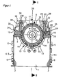
- the Fig. 1 and 2 show the invention at a glance.
- the device shown has a substantially symmetrical structure based on a machine base frame with two plane-parallel transverse walls 1, which are connected in their lower corners of lower longitudinal beams 2 and in their upper corners of upper longitudinal members 3 together.
- the longitudinal walls 4 are formed over their entire surface of doors 5, which are pivotable about the hinges 6 for opening and closing the housing and thus ensure accessibility to the interior of the device.
- a bracket 7 is welded in each case for receiving a shaft bearing 8.
- the shaft bearing 8 carry a rotor 9, which is essentially formed by a rotor drum 11, in the front side in each case a stub shaft 10 rotatably engages.
- the two stub shafts 10 extend with their free ends through openings in the transverse walls 1 to the shaft bearings 8.
- the rotor 9 is fitted over its circumference with a plurality of tool units 12, which are spaced apart both in the circumferential direction and in the axial direction.
- Each tool unit 12 is replaceably mounted in a receptacle on the lateral surface of the rotor drum 11, which is under FIG. 5 is described in more detail.
- the rotor 9 can be operated in both directions of rotation.
- the lower peripheral portion of the rotor 9 is surrounded by a screen web, which is formed in the present example of four sieve elements 13.
- Each sieve element 13 consists essentially of a portafilter 14, on which a perforated screen 15 is clamped.
- two sieve elements 13 extend in mirror image over approximately a quarter of the rotor circumference ( FIG. 1 ); longitudinally two sieve elements 13 follow each other axially ( FIG. 2 ).
- axle bearings 17 are arranged on the inside of the transverse wall 1 and on both sides of an intermediate wall, in which the filter holder 14 are rotatably mounted.
- the sieve elements 13 can each be pivoted downwards. With the doors 5 open access to the perforated screens 15 and the rotor 9 is thus ensured.
- the upper longitudinal beams 3 each serve for the stationary mounting of an axially parallel stator device, with a stator tool carrier 19, which extends over the entire axial distance of the two transverse walls 1 away.
- the top of Statorwerkmaschinechtiss 19 is inclined to the rotor 9 and forms a support surface for plate-shaped stator 21, which are clamped by means of clamping plates 22 and clamping screws 23 against the Statorwerkmaschineitati 19.
- In the area of the outer longitudinal sides of the Statortechnikmaschinemaschine 1976 19 also see adjusting screws 24, with which a radial adjustment or readjustment of the stator 21 can be made to ensure the intended working gap between the tool units 12 of the rotor 9 and the stator.
- the rotor 9 and the stator device thus have a substantially symmetrical structure to the vertical plane through the axis of rotation.
- the supply of the feed material via a vertical feed chute 25, connect the longitudinal walls 26 in the vertical direction directly to the stator.
- the longitudinal walls 26 In the connection region to the stator devices, the longitudinal walls 26 each have an opening 27 which extends from the one transverse wall 1 to the opposite.
- the transverse walls of the feed chute 25 are reinforced with respect to the transverse walls 1 of the machine base frame and continue upwards beyond the rotor 9.
- Each opening 27 is closed by a flap 28, which is mounted analogously to the screen elements 13 pivotally mounted in the transverse walls 1.
- the pivot axes 29 of the flaps 28 lie in the region of the upper longitudinal edge of a flap 28, where axial bearing journals are provided for this purpose.
- To protect the terminal gap between a movable flap 28 and the upwardly continuing rigid portion of the Zutechnologyschachts 25 have the longitudinal walls 26 on its inner side along its lower edge in each case a strip-shaped skirt 30 which overlaps the upper longitudinal edge of the flap 28.
- a deflector plate 33 extends over its entire length and extends inclined towards its free edge in order to prevent accumulation of material in the swivel range of the flaps 28.
- the drive of the flaps 28 is analogous to the drive of the sieve elements 13 by means of cylinder piston units, not shown, whose cylinders are fixedly connected to the outside of the transverse walls of the feed chute 25, while the movable actuating piston each seated on a rotationally fixed on the journal of the flaps 28 Lever is articulated.
- the cylinder piston units By extending the cylinder piston units, the pivotal movement of the flaps 28 is generated.
- the Fig. 3 to 6 show the closer construction of a tool unit 12 and its attachment to the rotor 9.
- the tool unit 12 comprises a tool carrier 34 which is composed of a first sub-carrier 31 and a second sub-carrier 32, which have an identical structure.
- Each sub-carrier 31, 32 has approximately cuboid shape with a flat bottom 35 and plan end faces 36, wherein the edges are chamfered.
- the front side 37 of the tool sub-carriers 31, 32 essentially serves to receive any number of tools, which in the present example are formed by four side-by-side, plate-shaped cutting crowns 38 with a square outline.
- Each cutting crown 38 is aligned so that its one diagonal runs parallel to the longitudinal direction of the sub-beams 31, 32 and the other diagonal perpendicular to it.
- the upper sides of the sub-carriers 31, 32 follow the course of the effective edge 41 while maintaining a small edge distance, resulting in a small radial projection of the cutting crowns 38 over the sub-carriers 31, 32.
- the cutting crowns 38 are arranged in receptacles 39 on the front side 37 of the carriers 31, 32.
- the pictures 39 are each formed by a to the rear side 42 of the sub-carrier 31, 32 out offset bearing surface 40.
- strip-shaped support surfaces 43 which receive two adjacent sides of a cutting bit 38 form fit.
- the transition between the two support surfaces 43 is formed by a fillet 44.
- the bearing surfaces 40 each have a central through-bore 46 for the passage of a fastening screw 47 ( Fig. 5 ). To illustrate this fact is in FIG. 3 the left in the drawing plane cutting crown 38 is not shown.
- the back 42 of the sub-carrier 31, 32 is substantially planar. In the exit region of the through holes 46, however, local recesses 48 are provided, in which the ends of the fastening screws 47 are anchored by means of nuts screwed 49. Below the recesses 48 at about half the distance to the bottom 35 of the sub-carrier 31, 32 can be seen a parallel to the bottom 35 extending keyway 50, which is intended for the positive reception of a Passefeder 51.
- FIGS. 3 and 5 It can be seen that in order to obtain a tool unit 12 according to the invention and its preparation for installation in a rotor 9, two sub-carriers 31, 32 are placed congruently against one another with their rear sides 42. In the common contact plane 52 while the key 51 ensures the centering of the first sub-carrier 31 relative to the second sub-carrier 32.
- Such a prepared tool unit 12 is inserted into a receptacle on the rotor 9, where the fixation solely by clamping with the aid of a radially clamped clamping wedge 53rd takes place, which exerts a relative to the axis of rotation tangentially directed clamping force on the tool unit 12.
- an inclined side surface of the clamping wedge 53 cooperates with a likewise inclined wall surface of a tool holder ( Fig. 5 ).
- Fig. 6 shows the contact region of two adjacently arranged on a sub-carrier 31, 32, rectangular or square processing tools in the form of cutting crowns 38.
- the opposing tips have flats 54 in the end, which allow a full-surface juxtaposition of the processing tools in the region of the flats 54.
- This has the advantage that even after occurrence of the first signs of wear, the effective edge 41 formed by the entirety of the processing tools is maintained throughout.
- advantageous size of the flats 54 results when the diagonal spacing of the flats corresponds approximately to 0.9 times to 0.95 times the distance between the two other peaks without flattening.
- the invention is not limited to the present embodiment, but rather also includes embodiments in which a tool extends integrally over an entire sub-carrier. Likewise, embodiments are possible in which the effective edge formed by the tools has a deviating from the zigzag course, for example, runs straight or undulating.
Landscapes
- Engineering & Computer Science (AREA)
- Food Science & Technology (AREA)
- Crushing And Pulverization Processes (AREA)
Applications Claiming Priority (1)
| Application Number | Priority Date | Filing Date | Title |
|---|---|---|---|
| DE102011119589A DE102011119589A1 (de) | 2011-11-29 | 2011-11-29 | Werkzeugeinheit und Schneid- oder Stanzwerkzeug für eine Zerkleinerungsvorrichtung sowie damit ausgerüstete Vorrichtung |
Publications (3)
| Publication Number | Publication Date |
|---|---|
| EP2599553A2 true EP2599553A2 (fr) | 2013-06-05 |
| EP2599553A3 EP2599553A3 (fr) | 2013-09-25 |
| EP2599553B1 EP2599553B1 (fr) | 2018-09-26 |
Family
ID=47290542
Family Applications (1)
| Application Number | Title | Priority Date | Filing Date |
|---|---|---|---|
| EP12007946.2A Not-in-force EP2599553B1 (fr) | 2011-11-29 | 2012-11-26 | Unité d'outil et outil de coupe ou d'estampillage pour un dispositif de broyage, et dispositif équipé de celui-ci |
Country Status (3)
| Country | Link |
|---|---|
| US (1) | US8967515B2 (fr) |
| EP (1) | EP2599553B1 (fr) |
| DE (1) | DE102011119589A1 (fr) |
Cited By (2)
| Publication number | Priority date | Publication date | Assignee | Title |
|---|---|---|---|---|
| EP2848311A1 (fr) * | 2013-09-11 | 2015-03-18 | Manuel Lindner | Lame pour un dispositif de découpe |
| CN114887732A (zh) * | 2022-05-20 | 2022-08-12 | 重庆电子工程职业学院 | 一种自动换刀的煤矿粉碎机 |
Families Citing this family (6)
| Publication number | Priority date | Publication date | Assignee | Title |
|---|---|---|---|---|
| US10864523B2 (en) * | 2014-05-20 | 2020-12-15 | Eco Green Equipment, Llc | Shredder blade assembly |
| US20170252749A1 (en) * | 2016-03-03 | 2017-09-07 | Daniel T. Miller | Processing blade |
| US10128238B2 (en) | 2016-08-09 | 2018-11-13 | International Business Machines Corporation | Integrated circuit having oxidized gate cut region and method to fabricate same |
| US10662950B2 (en) | 2016-10-31 | 2020-05-26 | Roper Pump Company | Progressing cavity device with cutter disks |
| EP3601684B1 (fr) * | 2017-03-31 | 2022-03-02 | Stanley Black & Decker, Inc. | Processeur de matériaux lourds |
| IT201900006240A1 (it) * | 2019-04-23 | 2020-10-23 | Seppi M S P A | Machina di trinciatura e taglio di materiale |
Citations (1)
| Publication number | Priority date | Publication date | Assignee | Title |
|---|---|---|---|---|
| DE19537581A1 (de) | 1995-10-09 | 1997-04-10 | Vecoplan Maschf Gmbh | Messeranordnung für eine Zerkleinerungsvorrichtung, zugehöriges Messer und Verfahren zu dessen Herstellung |
Family Cites Families (13)
| Publication number | Priority date | Publication date | Assignee | Title |
|---|---|---|---|---|
| US3314617A (en) * | 1964-01-29 | 1967-04-18 | Noble & Wood Machine Co | Pulper defibering means |
| US3857520A (en) * | 1972-10-27 | 1974-12-31 | Unice Machine Co | Oscillating anvil disintegrator |
| US4854508A (en) * | 1988-10-06 | 1989-08-08 | Columbus Mckinnon Corporation | Tire shredding machine |
| US5318231A (en) * | 1992-10-20 | 1994-06-07 | Norman J. Emanuel | Rotary shredding cutters |
| US5375775A (en) * | 1993-08-20 | 1994-12-27 | Keller; Mark E. | Tire recycling apparatus and method |
| FI105657B (fi) * | 1998-10-14 | 2000-09-29 | Bmh Wood Technology Oy | Murskainroottori ja menetelmä murskainroottorin vaippapinnan työstämiseksi |
| FI105656B (fi) * | 1998-10-14 | 2000-09-29 | Bmh Wood Technology Oy | Murskainroottorin hammas |
| US6343755B1 (en) * | 2000-03-31 | 2002-02-05 | Randel L. Barclay | Tire shredding machinery |
| FR2809333B1 (fr) * | 2000-05-25 | 2002-08-16 | Precimeca | Broyeur de dechets perfectionne, parties constitutives et procede de maintenance |
| DE10146773A1 (de) * | 2001-09-22 | 2003-04-17 | Deere & Co | Befestigungsanordnung zur Befestigung von Schlägeln an einem Rotor eines Strohhäckslers |
| EP1362639A1 (fr) * | 2002-05-08 | 2003-11-19 | UNTERWURZACHER PATENTVERWERTUNGSGESELLSCHAFT mbH | Broyeur pour le proyage de matériau |
| FR2908671B1 (fr) * | 2006-11-17 | 2009-02-13 | Precimeca Sa | Dispositif de broyage de dechets |
| SE0700048L (sv) * | 2007-01-12 | 2008-05-20 | Iggesund Tools Ab | Huggkniv samt förfarande för framställning av en huggkniv |
-
2011
- 2011-11-29 DE DE102011119589A patent/DE102011119589A1/de not_active Ceased
-
2012
- 2012-11-26 EP EP12007946.2A patent/EP2599553B1/fr not_active Not-in-force
- 2012-11-29 US US13/688,874 patent/US8967515B2/en not_active Expired - Fee Related
Patent Citations (1)
| Publication number | Priority date | Publication date | Assignee | Title |
|---|---|---|---|---|
| DE19537581A1 (de) | 1995-10-09 | 1997-04-10 | Vecoplan Maschf Gmbh | Messeranordnung für eine Zerkleinerungsvorrichtung, zugehöriges Messer und Verfahren zu dessen Herstellung |
Cited By (2)
| Publication number | Priority date | Publication date | Assignee | Title |
|---|---|---|---|---|
| EP2848311A1 (fr) * | 2013-09-11 | 2015-03-18 | Manuel Lindner | Lame pour un dispositif de découpe |
| CN114887732A (zh) * | 2022-05-20 | 2022-08-12 | 重庆电子工程职业学院 | 一种自动换刀的煤矿粉碎机 |
Also Published As
| Publication number | Publication date |
|---|---|
| DE102011119589A1 (de) | 2013-05-29 |
| EP2599553B1 (fr) | 2018-09-26 |
| EP2599553A3 (fr) | 2013-09-25 |
| US8967515B2 (en) | 2015-03-03 |
| US20130134250A1 (en) | 2013-05-30 |
Similar Documents
| Publication | Publication Date | Title |
|---|---|---|
| EP2599553B1 (fr) | Unité d'outil et outil de coupe ou d'estampillage pour un dispositif de broyage, et dispositif équipé de celui-ci | |
| EP2218507B1 (fr) | Dispositif de broyage de matériaux de chargement dotés d'éléments de démoulage | |
| EP2012927B1 (fr) | Dispositif de desintegration | |
| EP2428274B1 (fr) | Dispositif de broyage de matériaux de chargement | |
| EP2679309B1 (fr) | Dispositif de broyage comprenant un rotor de broyage avec lame traversante | |
| DE102009060523A1 (de) | Zerkleinerungsvorrichtung mit Gegenmessereinrichtung | |
| EP1843891B1 (fr) | Plaque a matrices destinee a une presse a comprimes rotative et presse a comprimes rotative | |
| EP1731223B1 (fr) | Désintégrateur des déchets | |
| EP2374544B1 (fr) | Dispositif de broyage de matériaux compostables | |
| EP2082807B1 (fr) | Dispositif de broyage doté de rotors opposés | |
| EP3315201B2 (fr) | Broyeur pour une machine à broyer | |
| DE102009020712A1 (de) | Vorrichtung zum Bearbeiten von Aufgabegut mit einem Rotor-Stator-System | |
| EP1899072B1 (fr) | Broyeur | |
| DE102007043687A1 (de) | Werkzeug für eine Zerkleinerungsvorrichtung für kompostierbares Abfallmaterial | |
| DE102007040046B4 (de) | Rotorshredder | |
| EP1099481B1 (fr) | Machine de broyage | |
| DE112011104021T5 (de) | Tischeinheit für eine Materialzerkleinerungsmaschine | |
| DE602004008495T2 (de) | Industrieller Schredder | |
| EP3356048B1 (fr) | Rotor pour un dispositif de broyage | |
| EP1428928B1 (fr) | Dispositif pour le broyage de matériaux et élément de broyage pour un tel dispositif | |
| DE202021003040U1 (de) | Vorrichtung zur Rüstung eines Messerrings eines Messerringzerspaners | |
| EP2549892B1 (fr) | Porte-couteaux pour dispositif de désintégration de matière organique | |
| DE102005050105B4 (de) | Schneidwerk für eine Zerkleinerungsmaschine und Verfahren zur Herstellung des Schneidwerkes | |
| EP3892378A1 (fr) | Couteau pour un dispositif de broyage | |
| DE102010054994B4 (de) | Hackmesserwalze für eine Holzhackmaschine |
Legal Events
| Date | Code | Title | Description |
|---|---|---|---|
| PUAI | Public reference made under article 153(3) epc to a published international application that has entered the european phase |
Free format text: ORIGINAL CODE: 0009012 |
|
| AK | Designated contracting states |
Kind code of ref document: A2 Designated state(s): AL AT BE BG CH CY CZ DE DK EE ES FI FR GB GR HR HU IE IS IT LI LT LU LV MC MK MT NL NO PL PT RO RS SE SI SK SM TR |
|
| AX | Request for extension of the european patent |
Extension state: BA ME |
|
| RIC1 | Information provided on ipc code assigned before grant |
Ipc: B02C 18/14 20060101AFI20130503BHEP Ipc: B02C 18/18 20060101ALI20130503BHEP |
|
| PUAL | Search report despatched |
Free format text: ORIGINAL CODE: 0009013 |
|
| AK | Designated contracting states |
Kind code of ref document: A3 Designated state(s): AL AT BE BG CH CY CZ DE DK EE ES FI FR GB GR HR HU IE IS IT LI LT LU LV MC MK MT NL NO PL PT RO RS SE SI SK SM TR |
|
| AX | Request for extension of the european patent |
Extension state: BA ME |
|
| RIC1 | Information provided on ipc code assigned before grant |
Ipc: B02C 18/18 20060101ALI20130821BHEP Ipc: B02C 18/14 20060101AFI20130821BHEP |
|
| 17P | Request for examination filed |
Effective date: 20140108 |
|
| RBV | Designated contracting states (corrected) |
Designated state(s): AL AT BE BG CH CY CZ DE DK EE ES FI FR GB GR HR HU IE IS IT LI LT LU LV MC MK MT NL NO PL PT RO RS SE SI SK SM TR |
|
| RAP1 | Party data changed (applicant data changed or rights of an application transferred) |
Owner name: PALLMANN MASCHINENFABRIK GMBH & CO. KG |
|
| GRAJ | Information related to disapproval of communication of intention to grant by the applicant or resumption of examination proceedings by the epo deleted |
Free format text: ORIGINAL CODE: EPIDOSDIGR1 |
|
| GRAP | Despatch of communication of intention to grant a patent |
Free format text: ORIGINAL CODE: EPIDOSNIGR1 |
|
| GRAP | Despatch of communication of intention to grant a patent |
Free format text: ORIGINAL CODE: EPIDOSNIGR1 |
|
| INTG | Intention to grant announced |
Effective date: 20180529 |
|
| GRAS | Grant fee paid |
Free format text: ORIGINAL CODE: EPIDOSNIGR3 |
|
| GRAA | (expected) grant |
Free format text: ORIGINAL CODE: 0009210 |
|
| AK | Designated contracting states |
Kind code of ref document: B1 Designated state(s): AL AT BE BG CH CY CZ DE DK EE ES FI FR GB GR HR HU IE IS IT LI LT LU LV MC MK MT NL NO PL PT RO RS SE SI SK SM TR |
|
| REG | Reference to a national code |
Ref country code: GB Ref legal event code: FG4D Free format text: NOT ENGLISH |
|
| REG | Reference to a national code |
Ref country code: CH Ref legal event code: EP |
|
| REG | Reference to a national code |
Ref country code: AT Ref legal event code: REF Ref document number: 1045362 Country of ref document: AT Kind code of ref document: T Effective date: 20181015 |
|
| REG | Reference to a national code |
Ref country code: IE Ref legal event code: FG4D Free format text: LANGUAGE OF EP DOCUMENT: GERMAN |
|
| REG | Reference to a national code |
Ref country code: DE Ref legal event code: R096 Ref document number: 502012013488 Country of ref document: DE |
|
| REG | Reference to a national code |
Ref country code: NL Ref legal event code: MP Effective date: 20180926 |
|
| PG25 | Lapsed in a contracting state [announced via postgrant information from national office to epo] |
Ref country code: GR Free format text: LAPSE BECAUSE OF FAILURE TO SUBMIT A TRANSLATION OF THE DESCRIPTION OR TO PAY THE FEE WITHIN THE PRESCRIBED TIME-LIMIT Effective date: 20181227 Ref country code: BG Free format text: LAPSE BECAUSE OF FAILURE TO SUBMIT A TRANSLATION OF THE DESCRIPTION OR TO PAY THE FEE WITHIN THE PRESCRIBED TIME-LIMIT Effective date: 20181226 Ref country code: RS Free format text: LAPSE BECAUSE OF FAILURE TO SUBMIT A TRANSLATION OF THE DESCRIPTION OR TO PAY THE FEE WITHIN THE PRESCRIBED TIME-LIMIT Effective date: 20180926 Ref country code: NO Free format text: LAPSE BECAUSE OF FAILURE TO SUBMIT A TRANSLATION OF THE DESCRIPTION OR TO PAY THE FEE WITHIN THE PRESCRIBED TIME-LIMIT Effective date: 20181226 Ref country code: LT Free format text: LAPSE BECAUSE OF FAILURE TO SUBMIT A TRANSLATION OF THE DESCRIPTION OR TO PAY THE FEE WITHIN THE PRESCRIBED TIME-LIMIT Effective date: 20180926 Ref country code: FI Free format text: LAPSE BECAUSE OF FAILURE TO SUBMIT A TRANSLATION OF THE DESCRIPTION OR TO PAY THE FEE WITHIN THE PRESCRIBED TIME-LIMIT Effective date: 20180926 Ref country code: SE Free format text: LAPSE BECAUSE OF FAILURE TO SUBMIT A TRANSLATION OF THE DESCRIPTION OR TO PAY THE FEE WITHIN THE PRESCRIBED TIME-LIMIT Effective date: 20180926 |
|
| REG | Reference to a national code |
Ref country code: LT Ref legal event code: MG4D |
|
| PG25 | Lapsed in a contracting state [announced via postgrant information from national office to epo] |
Ref country code: AL Free format text: LAPSE BECAUSE OF FAILURE TO SUBMIT A TRANSLATION OF THE DESCRIPTION OR TO PAY THE FEE WITHIN THE PRESCRIBED TIME-LIMIT Effective date: 20180926 Ref country code: LV Free format text: LAPSE BECAUSE OF FAILURE TO SUBMIT A TRANSLATION OF THE DESCRIPTION OR TO PAY THE FEE WITHIN THE PRESCRIBED TIME-LIMIT Effective date: 20180926 Ref country code: HR Free format text: LAPSE BECAUSE OF FAILURE TO SUBMIT A TRANSLATION OF THE DESCRIPTION OR TO PAY THE FEE WITHIN THE PRESCRIBED TIME-LIMIT Effective date: 20180926 |
|
| PG25 | Lapsed in a contracting state [announced via postgrant information from national office to epo] |
Ref country code: PL Free format text: LAPSE BECAUSE OF FAILURE TO SUBMIT A TRANSLATION OF THE DESCRIPTION OR TO PAY THE FEE WITHIN THE PRESCRIBED TIME-LIMIT Effective date: 20180926 Ref country code: EE Free format text: LAPSE BECAUSE OF FAILURE TO SUBMIT A TRANSLATION OF THE DESCRIPTION OR TO PAY THE FEE WITHIN THE PRESCRIBED TIME-LIMIT Effective date: 20180926 Ref country code: NL Free format text: LAPSE BECAUSE OF FAILURE TO SUBMIT A TRANSLATION OF THE DESCRIPTION OR TO PAY THE FEE WITHIN THE PRESCRIBED TIME-LIMIT Effective date: 20180926 Ref country code: IS Free format text: LAPSE BECAUSE OF FAILURE TO SUBMIT A TRANSLATION OF THE DESCRIPTION OR TO PAY THE FEE WITHIN THE PRESCRIBED TIME-LIMIT Effective date: 20190126 Ref country code: CZ Free format text: LAPSE BECAUSE OF FAILURE TO SUBMIT A TRANSLATION OF THE DESCRIPTION OR TO PAY THE FEE WITHIN THE PRESCRIBED TIME-LIMIT Effective date: 20180926 Ref country code: ES Free format text: LAPSE BECAUSE OF FAILURE TO SUBMIT A TRANSLATION OF THE DESCRIPTION OR TO PAY THE FEE WITHIN THE PRESCRIBED TIME-LIMIT Effective date: 20180926 Ref country code: IT Free format text: LAPSE BECAUSE OF FAILURE TO SUBMIT A TRANSLATION OF THE DESCRIPTION OR TO PAY THE FEE WITHIN THE PRESCRIBED TIME-LIMIT Effective date: 20180926 Ref country code: RO Free format text: LAPSE BECAUSE OF FAILURE TO SUBMIT A TRANSLATION OF THE DESCRIPTION OR TO PAY THE FEE WITHIN THE PRESCRIBED TIME-LIMIT Effective date: 20180926 |
|
| PG25 | Lapsed in a contracting state [announced via postgrant information from national office to epo] |
Ref country code: SK Free format text: LAPSE BECAUSE OF FAILURE TO SUBMIT A TRANSLATION OF THE DESCRIPTION OR TO PAY THE FEE WITHIN THE PRESCRIBED TIME-LIMIT Effective date: 20180926 Ref country code: SM Free format text: LAPSE BECAUSE OF FAILURE TO SUBMIT A TRANSLATION OF THE DESCRIPTION OR TO PAY THE FEE WITHIN THE PRESCRIBED TIME-LIMIT Effective date: 20180926 Ref country code: PT Free format text: LAPSE BECAUSE OF FAILURE TO SUBMIT A TRANSLATION OF THE DESCRIPTION OR TO PAY THE FEE WITHIN THE PRESCRIBED TIME-LIMIT Effective date: 20190126 |
|
| REG | Reference to a national code |
Ref country code: DE Ref legal event code: R119 Ref document number: 502012013488 Country of ref document: DE |
|
| REG | Reference to a national code |
Ref country code: CH Ref legal event code: PL |
|
| PG25 | Lapsed in a contracting state [announced via postgrant information from national office to epo] |
Ref country code: DK Free format text: LAPSE BECAUSE OF FAILURE TO SUBMIT A TRANSLATION OF THE DESCRIPTION OR TO PAY THE FEE WITHIN THE PRESCRIBED TIME-LIMIT Effective date: 20180926 Ref country code: LU Free format text: LAPSE BECAUSE OF NON-PAYMENT OF DUE FEES Effective date: 20181126 Ref country code: MC Free format text: LAPSE BECAUSE OF FAILURE TO SUBMIT A TRANSLATION OF THE DESCRIPTION OR TO PAY THE FEE WITHIN THE PRESCRIBED TIME-LIMIT Effective date: 20180926 |
|
| PLBE | No opposition filed within time limit |
Free format text: ORIGINAL CODE: 0009261 |
|
| STAA | Information on the status of an ep patent application or granted ep patent |
Free format text: STATUS: NO OPPOSITION FILED WITHIN TIME LIMIT |
|
| REG | Reference to a national code |
Ref country code: BE Ref legal event code: MM Effective date: 20181130 |
|
| REG | Reference to a national code |
Ref country code: IE Ref legal event code: MM4A |
|
| GBPC | Gb: european patent ceased through non-payment of renewal fee |
Effective date: 20181226 |
|
| PG25 | Lapsed in a contracting state [announced via postgrant information from national office to epo] |
Ref country code: CH Free format text: LAPSE BECAUSE OF NON-PAYMENT OF DUE FEES Effective date: 20181130 Ref country code: LI Free format text: LAPSE BECAUSE OF NON-PAYMENT OF DUE FEES Effective date: 20181130 |
|
| 26N | No opposition filed |
Effective date: 20190627 |
|
| PG25 | Lapsed in a contracting state [announced via postgrant information from national office to epo] |
Ref country code: SI Free format text: LAPSE BECAUSE OF FAILURE TO SUBMIT A TRANSLATION OF THE DESCRIPTION OR TO PAY THE FEE WITHIN THE PRESCRIBED TIME-LIMIT Effective date: 20180926 Ref country code: IE Free format text: LAPSE BECAUSE OF NON-PAYMENT OF DUE FEES Effective date: 20181126 Ref country code: DE Free format text: LAPSE BECAUSE OF NON-PAYMENT OF DUE FEES Effective date: 20190601 Ref country code: FR Free format text: LAPSE BECAUSE OF NON-PAYMENT OF DUE FEES Effective date: 20181126 |
|
| PG25 | Lapsed in a contracting state [announced via postgrant information from national office to epo] |
Ref country code: BE Free format text: LAPSE BECAUSE OF NON-PAYMENT OF DUE FEES Effective date: 20181130 |
|
| PG25 | Lapsed in a contracting state [announced via postgrant information from national office to epo] |
Ref country code: GB Free format text: LAPSE BECAUSE OF NON-PAYMENT OF DUE FEES Effective date: 20181226 |
|
| REG | Reference to a national code |
Ref country code: AT Ref legal event code: MM01 Ref document number: 1045362 Country of ref document: AT Kind code of ref document: T Effective date: 20181126 |
|
| PG25 | Lapsed in a contracting state [announced via postgrant information from national office to epo] |
Ref country code: MT Free format text: LAPSE BECAUSE OF FAILURE TO SUBMIT A TRANSLATION OF THE DESCRIPTION OR TO PAY THE FEE WITHIN THE PRESCRIBED TIME-LIMIT Effective date: 20180926 Ref country code: AT Free format text: LAPSE BECAUSE OF NON-PAYMENT OF DUE FEES Effective date: 20181126 |
|
| PG25 | Lapsed in a contracting state [announced via postgrant information from national office to epo] |
Ref country code: TR Free format text: LAPSE BECAUSE OF FAILURE TO SUBMIT A TRANSLATION OF THE DESCRIPTION OR TO PAY THE FEE WITHIN THE PRESCRIBED TIME-LIMIT Effective date: 20180926 |
|
| PG25 | Lapsed in a contracting state [announced via postgrant information from national office to epo] |
Ref country code: HU Free format text: LAPSE BECAUSE OF FAILURE TO SUBMIT A TRANSLATION OF THE DESCRIPTION OR TO PAY THE FEE WITHIN THE PRESCRIBED TIME-LIMIT; INVALID AB INITIO Effective date: 20121126 Ref country code: CY Free format text: LAPSE BECAUSE OF FAILURE TO SUBMIT A TRANSLATION OF THE DESCRIPTION OR TO PAY THE FEE WITHIN THE PRESCRIBED TIME-LIMIT Effective date: 20180926 Ref country code: MK Free format text: LAPSE BECAUSE OF NON-PAYMENT OF DUE FEES Effective date: 20180926 |