EP2607943B1 - Lunettes - Google Patents
Lunettes Download PDFInfo
- Publication number
- EP2607943B1 EP2607943B1 EP20120192610 EP12192610A EP2607943B1 EP 2607943 B1 EP2607943 B1 EP 2607943B1 EP 20120192610 EP20120192610 EP 20120192610 EP 12192610 A EP12192610 A EP 12192610A EP 2607943 B1 EP2607943 B1 EP 2607943B1
- Authority
- EP
- European Patent Office
- Prior art keywords
- frame part
- lower frame
- spectacles
- upper frame
- end position
- Prior art date
- Legal status (The legal status is an assumption and is not a legal conclusion. Google has not performed a legal analysis and makes no representation as to the accuracy of the status listed.)
- Not-in-force
Links
- 230000005294 ferromagnetic effect Effects 0.000 claims description 17
- 229920003023 plastic Polymers 0.000 claims description 4
- 239000004033 plastic Substances 0.000 claims description 4
- 239000011521 glass Substances 0.000 description 26
- 239000000463 material Substances 0.000 description 5
- 230000005291 magnetic effect Effects 0.000 description 4
- 230000007246 mechanism Effects 0.000 description 3
- 230000004888 barrier function Effects 0.000 description 2
- 230000013011 mating Effects 0.000 description 2
- 230000001427 coherent effect Effects 0.000 description 1
- 238000010276 construction Methods 0.000 description 1
- 230000006872 improvement Effects 0.000 description 1
- 238000007373 indentation Methods 0.000 description 1
- 230000003993 interaction Effects 0.000 description 1
- 230000003313 weakening effect Effects 0.000 description 1
Images



Classifications
-
- G—PHYSICS
- G02—OPTICS
- G02C—SPECTACLES; SUNGLASSES OR GOGGLES INSOFAR AS THEY HAVE THE SAME FEATURES AS SPECTACLES; CONTACT LENSES
- G02C1/00—Assemblies of lenses with bridges or browbars
- G02C1/06—Bridge or browbar secured to or integral with closed rigid rims for the lenses
- G02C1/08—Bridge or browbar secured to or integral with closed rigid rims for the lenses the rims being tranversely split and provided with securing means
-
- G—PHYSICS
- G02—OPTICS
- G02C—SPECTACLES; SUNGLASSES OR GOGGLES INSOFAR AS THEY HAVE THE SAME FEATURES AS SPECTACLES; CONTACT LENSES
- G02C1/00—Assemblies of lenses with bridges or browbars
- G02C1/04—Bridge or browbar secured to or integral with partial rims, e.g. with partially-flexible rim for holding lens
-
- G—PHYSICS
- G02—OPTICS
- G02C—SPECTACLES; SUNGLASSES OR GOGGLES INSOFAR AS THEY HAVE THE SAME FEATURES AS SPECTACLES; CONTACT LENSES
- G02C5/00—Constructions of non-optical parts
- G02C5/02—Bridges; Browbars; Intermediate bars
-
- G—PHYSICS
- G02—OPTICS
- G02C—SPECTACLES; SUNGLASSES OR GOGGLES INSOFAR AS THEY HAVE THE SAME FEATURES AS SPECTACLES; CONTACT LENSES
- G02C2200/00—Generic mechanical aspects applicable to one or more of the groups G02C1/00 - G02C5/00 and G02C9/00 - G02C13/00 and their subgroups
- G02C2200/02—Magnetic means
-
- G—PHYSICS
- G02—OPTICS
- G02C—SPECTACLES; SUNGLASSES OR GOGGLES INSOFAR AS THEY HAVE THE SAME FEATURES AS SPECTACLES; CONTACT LENSES
- G02C2200/00—Generic mechanical aspects applicable to one or more of the groups G02C1/00 - G02C5/00 and G02C9/00 - G02C13/00 and their subgroups
- G02C2200/08—Modular frames, easily exchangeable frame parts and lenses
Definitions
- the invention relates to a pair of glasses, in particular a pair of glasses with a replaceable disc.
- Eyeglasses with interchangeable discs are for example from the WO 2010/003143 A1 and the FR 2 535 473 A1 known.
- An object of the invention is to improve the mechanism for replacing the lens of a pair of spectacles.
- the core of the invention is to form the frame of a pair of spectacles in such a way that two frame parts are interconnected in a central region, wherein the lower frame part is displaceable from an inserted end position to an extended end position for replacing the discs of the spectacles relative to the upper frame part.
- the shift is particularly linear.
- the lower frame part is displaceable in particular in the longitudinal direction.
- the directional information corresponds to the usual anatomical position and direction designations with respect to the intended use of glasses.
- the spectacle lens is arranged in this case substantially parallel to a frontal plane.
- the glasses are symmetrical to a sagittal plane.
- the longitudinal direction is defined by the line of intersection of the sagittal plane with the frontal plane. It is thus parallel to the body longitudinal axis and perpendicular to a transverse plane.
- top and bottom are to be understood relative to the transverse plane.
- the disc of the glasses in the frame can be fixed and unlocked.
- the lower frame part forms in the inserted end position a means for fixing the disc in the frame.
- the inserted end position is thus a locking or fixing position.
- the disc In the extended end position of the lower frame part, the disc can be removed from the frame.
- magnetic securing means are provided.
- at least one connected to the lower frame part ferromagnetic securing means is provided, which cooperates with at least one connected to the upper frame part ferromagnetic securing means.
- the securing means can be two magnets. It is also possible to form only one of the securing means as a permanent magnet, while the other is made of a ferromagnetic, magnetizable material.
- the magnetic securing means allow easy operation of the locking and changing mechanism without weakening the frame. By means of magnets, a high holding force can be achieved in a particularly space-saving manner.
- the securing means for securing the lower frame part in the extended end position may correspond to those for securing the lower frame part in the inserted end position.
- the securing means are advantageously integrated respectively in the frame parts. They are in particular positively integrated in recesses in the frame parts. They may for example be cylindrical and arranged in holes, in particular blind hole-like holes in the frame parts. You can vorteihaft we glued to the respective frame part. This allows a particularly secure arrangement of the securing means in the frame parts.
- two ferromagnetic securing means are integrated in the lower frame part. These are arranged offset in particular in the longitudinal direction against each other. You can each cooperate with a single securing means in the upper frame part. In this case, it may be advantageous to design exclusively the securing means in the upper frame part magnetically, while the securing means in the lower frame part may be made of a magnetizable material.
- the lower frame part secured by a mechanical securing element may be connected to the upper frame part.
- the mechanical securing element forms, in particular, an additional mechanical lock which prevents inadvertent release of the lower frame part from the upper frame part.
- the mechanical securing element can be detachable, for example for exchanging the lower frame part. It is also possible, the lower frame part unsolvable with connect to the upper frame part. This can allow a particularly robust embodiment of the glasses.
- the lower frame part may be formed in particular as a central web of the glasses.
- the lower frame part it is possible, in particular, for the lower frame part to encompass the at least one disk in each case only in a central region, ie. H. rests against the disc.
- the frame surrounds in this case, even in the retracted end position of the lower frame part, the at least one disc only partially. It lies circumferentially, in particular in a range of 40% to 100%, in particular in a range of 45% to 80%, in particular in a range of 50% to 70% on the circumference of the at least one disc.
- the lower frame part rests against the disc over a length of at most 10 cm, in particular at most 7 cm, in particular at most 4 cm.
- the glasses may also be advantageous to use the glasses with a full frame, d. H. a frame, which completely surrounds the disc or the glasses of the glasses, form.
- the frame parts in a side region of the glasses can be firmly connected to each other. They are preferably detachably connected to each other in the side area.
- a mechanical and / or magnetic connection can be provided.
- guide recesses may be provided for receiving an edge region of the disc or the discs.
- latching lugs can be provided in the edge region of the disk, which latching lugs interact with matching undercuts, in particular in the upper frame part.
- the locking lug and the matching undercuts are arranged in particular in the medial area of the glasses.
- notches may be provided in the disc which cooperate with mating projections on the frame. This also allows a fixation of the disc can be improved in the frame.
- the indentations and projections are provided in particular in a lateral region of the spectacles.
- a design of the glasses made of plastic allows one hand, a simple production, on the other hand, a particularly robust construction of the glasses and finally makes it possible to form the glasses very easily.
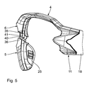
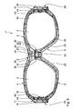
- a pair of glasses 1 comprises a frame 2, in which two discs 3 are interchangeably arranged.
- the discs 3 are shown in dashed lines in the figures.
- the glasses 1 are in particular a sports glasses or sunglasses.
- the frame 2 is advantageously made of plastic.
- the discs 3 may be made of plastic. They can also be made of glass.
- the discs 3 may also be formed contiguous.
- the spectacles 1 comprises at least one disc 3.
- the frame 2 comprises a first frame part 4 and a second frame part 5. It is in particular formed in two parts.
- the first frame part 4 is in particular an upper frame part.
- the second frame part 5 is in particular a lower frame part.
- On the first frame part 4 two eyeglasses 18 are attached.
- the temples 18 may be hinged to the first frame part 4. Instead of the temple 18 may also be provided an elastic band.
- the frame parts 4, 5 are connected to one another in a center region 6, which is also referred to as a middle section.
- the lower frame part 5 is displaceable for replacing the discs 3 relative to the upper frame part 4.
- a longitudinal direction 29 running perpendicular to a transverse direction 28, it can be displaced relative to the upper frame part 4 from an inserted end position into an extended end position.
- the magnet 30 is connected to the upper frame part 4. It is integrated in particular in the upper frame part 4. It is arranged in a form-fitting manner in a recess 32 in the upper frame part 4. It can be glued in the recess 32.
- the recess 32 is hollow cylindrical, in particular designed as a cylindrical bore.
- the magnet 31 is connected to the lower frame part 5.
- the magnet 31 is integrated in particular in the lower frame part 5. It is preferably integrated in a form-fitting manner in a recess, in particular a cylindrical bore or a cylindrical blind hole in the lower frame part 5. It can be glued to the lower frame part 5.
- the magnets 30, 31 are arranged in the frame parts 4, 5 such that they are adjacent in the inserted end position, in particular coaxial with each other.
- the magnets 30, 31 are arranged offset in Sagitalcardi 34 against each other.
- the magnets 30, 31 are in particular cylindrically shaped. They have a diameter of about 4 mm and a height of about 1.5 mm. Generally, the diameter of the magnets 30, 31 is in the range of 2 mm to 1 cm, in particular in the range of 3 mm to 5 mm. The height of the magnets 30, 31 is in particular in the range of 1 mm to 3 mm. The magnets 30, 31 may also be formed cuboid.
- the magnets 30, 31 are arranged such that the one pole of the magnet 30 faces the pole of the magnet 31 opposite thereto. They are thus arranged in particular such that they exert an attractive force on each other.
- the magnets 30, 31 cooperate with each other cooperating ferromagnetic elements 12.
- the cooperating ferromagnetic elements 12 may each be both formed as magnets. It is also possible to form only one of the ferromagnetic elements 12 as a magnet and the element 12 cooperating therewith made of a magnetizable material.
- a holding force of at least 1 N, in particular at least 5 N, in particular at least 10 N, can be generated.
- a further magnet 33 is connected to the lower frame part 5 for securing the lower frame part 5 in the extended end position.
- the magnet 33 is arranged offset in the longitudinal direction 29 to the magnet 31.
- the design and arrangement of the magnet 33 corresponds to that of the magnet 31.
- the magnet 33 is arranged in particular above the magnet 31. He is arranged in such a way that it is adjacent to the magnet 30 in the upper frame part 4 in the extended end position of the lower frame part 5, in particular coaxially.
- the magnets 30, 33 are in this case offset in Sagitalraum 34 against each other.
- the lower frame part 5 comprises in particular a guide tongue 35, which extends in the longitudinal direction 29.
- the guide tongue 35 is guided laterally by guide webs 36 of the upper frame part 4. It engages in the inserted state of the lower frame part 5 in a guide slot 37 in the upper frame part 4 a. It rests on a front guide wall 38 and on a rear guide wall 39.
- the lower frame part 5 is guided particularly securely and precisely in the upper frame part 4. It has in particular exactly one degree of freedom, d. H. it is linearly displaceable only in the longitudinal direction.
- the mechanical lock 40 secured to the upper frame part 4.
- the mechanical lock 40 may be formed as a projection, in particular as a latching nose. It can cooperate with a recess 41 designed to fit in the upper frame part 4.
- the barrier 40 generally forms a mechanical securing element.
- the barrier 40 may be releasable.
- the lower frame part 5 is interchangeable. It can also be fix.
- the lower frame part 5 is permanently connected to the upper frame part 4.
- the lower frame part may be formed as a central web 42 of the spectacles 1. It can especially nose pads 25 include. These may be permanently or detachably connected to the lower frame part 5.
- the frame 2 surrounds the discs 3 only partially in the retracted end position of the lower frame part 5. It lies circumferentially only about 55% on the circumference of the discs 3.
- the frame 2 bears circumferentially at 40% to 100%, in particular 45% to 80%, in particular 50% to 70%, of the disks 3.
- the lower frame part 5 is in this case over a length of at most 10 cm, in particular at most 7 cm, in particular at most 4 cm to the disc 3 at.
- the lower frame part 5 is replaceable.
- the lower frame part 5 on its guide tongue 35 has a latching nose.
- the locking lug is formed adapted to a latching opening in the upper frame part 4.
- the guide tongue 35 is slightly flexible in the sagittal direction 34 in order to enable latching of the latching lug in the latching opening.
- the frame parts 4, 5 each have a groove-like recess 19, in which the disc 3 is used.
- the disc 3 is in particular form-fitting manner in the recess 19 can be used.
- the depression 19 forms a guide recess for at least partially receiving a marginal region of the disc 3.
- the depression 19 has a depth in the range of 1 to 3 mm. It is designed such that the depression 19 in the second frame part 5 forms a continuation, in particular a stepless continuation, of the recess 19 in the first frame part 4.
- the edge region of the disc 3 has a latching lug 20 which cooperates with a matching undercut 21 in the upper frame part 4 for fixing the disc 3 in the frame 2.
- the locking lug 20 and the undercut 21 are arranged insbesondre in the central portion 6 of the spectacles 1.
- the discs 3 each have a notch 43 in the lateral edge region, which cooperates with a mating projection 44 on the upper frame part 4 for fixing the disc 3 in the frame 2.
- the upper frame part 4 is at least partially flexible. In particular, it has at least one flexibly formed section.
- the lower frame part 5 is connected to the upper frame part 4 both in the middle region 6 and in lateral side regions 11.
- the frame 2 thus surrounds the discs 3 completely. It is a so-called full frame.
- a detachable connection 45 is provided between the frame parts 4, 5 in the lateral side region 11.
- the releasable connection 45 may be formed as a magnetic and / or latching connection. Due to the surrounding frame 2, the discs 3 are held particularly secure. Incidentally, reference is made to the description of the preceding embodiment.
- the frame parts 4, 5 are fixedly connected to one another in the lateral side regions 11. you are thus formed coherent.
- the lower frame part 5 is in particular made of a flexible material. This ensures that the lower frame part 5, despite the connection with the upper frame part 4 in the side regions 11 in the central region 6 relative to the upper frame part 4 is displaceable in an extended end position. The displaceability of the lower frame part 5 can be improved in this case by one or more joint elements in the lower frame part 5.
- the magnets 30 and / or 31 and / or 33 are completely integrated in the respective frame part 4, 5. They are in particular completely surrounded by the material of the respective frame part 4, 5. They are thus particularly secure against accidental falling out.
- the magnets 30 and / or 31 and / or 33 may also be helical.
- they can have an external thread.
- they can be screwed into a matching internal thread in the respective frame part 4, 5.
Landscapes
- Physics & Mathematics (AREA)
- Health & Medical Sciences (AREA)
- General Physics & Mathematics (AREA)
- Ophthalmology & Optometry (AREA)
- Optics & Photonics (AREA)
- Eyeglasses (AREA)
Claims (14)
- Lunettes (1) comprenanta. au moins un verre (3) etb. une monture (2), s'étendant dans la direction transversale (28), comportanti. une partie de monture supérieure (4) etii. une partie de monture inférieure (5),c. la partie de monture inférieure (5) étant reliée avec la partie de monture supérieure (4) au moins dans une zone centrale (6),d. au moins un verre (3) pouvant être échangé, ete. la partie de monture inférieure (5), pouvant être déplacée par rapport à la partie de monture supérieure (4) à partir d'une position finale insérée vers une position finale débrayée dans une direction longitudinale (29), s'étendant perpendiculairement par rapport à la direction transversale (28), pour l'échange d'au moins un verre (3),f. caractérisées en ce qu'au moins un système de sécurisation (33) ferromagnétique relié avec la partie de monture inférieure (5) est prévu dans la position finale débrayée pour la sécurisation de la partie de monture inférieure (5), système qui agit conjointement avec au moins un système de sécurisation (30) ferromagnétique relié avec la partie de monture supérieure (4).
- Lunettes (1) selon la revendication 1, caractérisées en ce qu'au moins un système de sécurisation (31) ferromagnétique relié avec la partie de monture inférieure (5) est prévu pour la sécurisation de la partie de monture inférieure (5) dans la position finale insérée, système qui agit conjointement avec au moins un système de sécurisation (30) ferromagnétique relié avec la partie de monture supérieure (4).
- Lunettes (1) selon l'une des revendications 1 ou 2, caractérisées en ce que les systèmes de sécurisation (30, 31, 33) ferromagnétiques sont chacun intégrés par complémentarité de formes dans des évidements (32) dans les parties de monture (4, 5).
- Lunettes (1) selon l'une des revendications précédentes, caractérisées en ce qu'au moins deux systèmes de sécurisation (31, 33) ferromagnétiques sont intégrés dans la partie de monture inférieure (5).
- Lunettes (1) selon la revendication 4, caractérisées en ce que les systèmes de sécurisation (31, 33) ferromagnétiques sont disposés, espacés, opposés l'un par rapport à l'autre, dans la direction longitudinale (29), dans la partie de monture inférieure (5).
- Lunettes (1) selon l'une des revendications précédentes, caractérisées en ce que la partie de monture inférieure (5) est reliée avec la partie de monture supérieure (4) de manière sécurisée au moyen d'un élément de sécurisation mécanique (40).
- Lunettes (1) selon la revendication 6, caractérisées en ce que l'élément de sécurisation mécanique (40) peut être détaché.
- Lunettes (1) selon l'une des revendications précédentes, caractérisées en ce que la partie de monture inférieure (5) est reliée de manière non détachable avec la partie de monture supérieure (4).
- Lunettes (1) selon l'une des revendications précédentes, caractérisées en ce que la partie de monture inférieure (5) est conçue sous la forme d'un montant central (42).
- Lunettes (1) selon l'une des revendications précédentes, caractérisées en ce que la monture (2) entoure également, purement et simplement, partiellement, au moins un verre (3) dans la position finale insérée de la partie de monture inférieure (5).
- Lunettes (1) selon l'une des revendications précédentes, caractérisées en ce que la partie de monture supérieure (4) et/ou la partie de monture inférieure (5) présentent au moins une portion conçue flexible.
- Lunettes (1) selon la revendication 11, caractérisées en ce que la partie de monture supérieure (4) présente au moins une cavité (19) en forme de rainure dans laquelle le verre (3) peut être inséré.
- Lunettes (1) selon la revendication 12, caractérisées en ce que le verre (3) présente au moins une saillie (20) en butée dans une zone du bord qui agit conjointement avec une fixation de retenue (21), qui lui est complémentaire, dans la partie de monture supérieure (4) pour la fixation du verre (3) dans la monture (2).
- Lunettes (1) selon l'une des revendications précédentes, caractérisées en ce qu'au moins une des parties de monture (4, 5) est en matière plastique.
Priority Applications (1)
| Application Number | Priority Date | Filing Date | Title |
|---|---|---|---|
| SI201230068T SI2607943T1 (sl) | 2011-12-19 | 2012-11-14 | OÄŤala |
Applications Claiming Priority (1)
| Application Number | Priority Date | Filing Date | Title |
|---|---|---|---|
| DE201110089034 DE102011089034A1 (de) | 2011-12-19 | 2011-12-19 | Brille |
Publications (2)
| Publication Number | Publication Date |
|---|---|
| EP2607943A1 EP2607943A1 (fr) | 2013-06-26 |
| EP2607943B1 true EP2607943B1 (fr) | 2014-05-21 |
Family
ID=47257492
Family Applications (1)
| Application Number | Title | Priority Date | Filing Date |
|---|---|---|---|
| EP20120192610 Not-in-force EP2607943B1 (fr) | 2011-12-19 | 2012-11-14 | Lunettes |
Country Status (3)
| Country | Link |
|---|---|
| EP (1) | EP2607943B1 (fr) |
| DE (1) | DE102011089034A1 (fr) |
| SI (1) | SI2607943T1 (fr) |
Cited By (1)
| Publication number | Priority date | Publication date | Assignee | Title |
|---|---|---|---|---|
| US11460715B2 (en) | 2019-02-28 | 2022-10-04 | Smith Sport Optics, Inc. | Eyewear lens interchange with magnetic latch |
Families Citing this family (2)
| Publication number | Priority date | Publication date | Assignee | Title |
|---|---|---|---|---|
| CN110018574B (zh) * | 2019-03-25 | 2019-11-22 | 东阳韵源自动化科技有限公司 | 方便使用的镜框 |
| US20240103294A1 (en) * | 2022-09-27 | 2024-03-28 | Metrex Research, LLC | Lens holding device |
Family Cites Families (7)
| Publication number | Priority date | Publication date | Assignee | Title |
|---|---|---|---|---|
| FR2535473B1 (fr) * | 1982-11-02 | 1985-11-29 | Cottet Freres | Face pour monture de lunettes |
| DE8605669U1 (de) * | 1986-03-01 | 1986-04-10 | Weber, Karl, 7000 Stuttgart | Brille, insbesondere Sonnenbrille |
| DE4118018C1 (fr) * | 1991-06-01 | 1992-05-07 | Uvex Winter Optik Gmbh, 8510 Fuerth, De | |
| US5467148A (en) * | 1993-11-08 | 1995-11-14 | Bausch & Lomb Incorporated | Eyewear having interchangeable lenses |
| US5703669A (en) * | 1996-03-18 | 1997-12-30 | Park; James S. | Sunglasses including quick release lens retainer #5 |
| FR2867573B1 (fr) * | 2004-03-15 | 2006-09-29 | Charles Ayache | Monture de lunettes a assemblage magnetique des verres |
| CN102067013B (zh) | 2008-07-03 | 2016-02-10 | 奥克利有限公司 | 浮动镜片安装系统 |
-
2011
- 2011-12-19 DE DE201110089034 patent/DE102011089034A1/de not_active Withdrawn
-
2012
- 2012-11-14 EP EP20120192610 patent/EP2607943B1/fr not_active Not-in-force
- 2012-11-14 SI SI201230068T patent/SI2607943T1/sl unknown
Cited By (2)
| Publication number | Priority date | Publication date | Assignee | Title |
|---|---|---|---|---|
| US11460715B2 (en) | 2019-02-28 | 2022-10-04 | Smith Sport Optics, Inc. | Eyewear lens interchange with magnetic latch |
| US12038626B2 (en) | 2019-02-28 | 2024-07-16 | Smith Sport Optics, Inc. | Eyewear lens interchange with magnetic latch |
Also Published As
| Publication number | Publication date |
|---|---|
| DE102011089034A1 (de) | 2013-06-20 |
| EP2607943A1 (fr) | 2013-06-26 |
| SI2607943T1 (sl) | 2014-09-30 |
Similar Documents
| Publication | Publication Date | Title |
|---|---|---|
| EP3122294B9 (fr) | Dispositif intraoral d'occlusion | |
| DE202011103166U1 (de) | Brillenscharnier | |
| EP1877853B1 (fr) | Dispositif pour changer des branches, des tenons et des barres de montures de lunettes sans bord, ainsi que des branches et des tenons de montures de lunettes en metal ou en matiere plastique | |
| DE102013202336B4 (de) | Brille mit auswechselbarem Brillenglas | |
| EP1821132A1 (fr) | Charnière à ressort pour lunettes | |
| EP0332664B1 (fr) | Guidage pour tiroirs de preference en plastique | |
| DE69722577T2 (de) | Schnellkupplung, insbesondere zur Befestigung eines WC-Sitz-Deckels am Klosett | |
| EP2607943B1 (fr) | Lunettes | |
| DE102009012836A1 (de) | Federscharnier für Brillen | |
| AT508941B1 (de) | Brille | |
| AT500217B1 (de) | Federscharnier für eine brille | |
| DE10226103C1 (de) | Anordnung mit einer Backe, einem Bügel und einem Gelenk für eine Brille | |
| EP3602183A1 (fr) | Lunettes | |
| DE202016102990U1 (de) | Brillenglas-Verbindungsanordnung | |
| DE69808806T2 (de) | Mehrzweck-nasenstütze für brillengestell | |
| DE102021133863B3 (de) | Brille, Schrimkörper sowie Verfahren zur Montage und/oder Demontage eines Schirmkörpers aneinem Brillenrahmen einer Brille | |
| DE202014010238U1 (de) | Federscharnier-Gehäuse, Federscharnier und Federscharnier-Brillenbügel sowie Brille mit Federscharnier | |
| DE212010000227U1 (de) | Austauschbare Fahrradschuhhalterung | |
| DE69602600T2 (de) | Brillengestell | |
| DE202015104638U1 (de) | Befestigungskonstruktion eines Brillenglases | |
| DE3729116A1 (de) | Brille mit auswechselbarem glas bzw. glaesern | |
| DE102007025762A1 (de) | Schlittensystem für Werkzeugmaschinen | |
| EP3488286B1 (fr) | Charnière à ressort pour lunettes | |
| AT511093B1 (de) | Federscharnier für eine brille | |
| DE202014103447U1 (de) | Brillengestell mit wechselbarem Bügel |
Legal Events
| Date | Code | Title | Description |
|---|---|---|---|
| AK | Designated contracting states |
Kind code of ref document: A1 Designated state(s): AL AT BE BG CH CY CZ DE DK EE ES FI FR GB GR HR HU IE IS IT LI LT LU LV MC MK MT NL NO PL PT RO RS SE SI SK SM TR |
|
| AX | Request for extension of the european patent |
Extension state: BA ME |
|
| PUAI | Public reference made under article 153(3) epc to a published international application that has entered the european phase |
Free format text: ORIGINAL CODE: 0009012 |
|
| 17P | Request for examination filed |
Effective date: 20131209 |
|
| RBV | Designated contracting states (corrected) |
Designated state(s): AL AT BE BG CH CY CZ DE DK EE ES FI FR GB GR HR HU IE IS IT LI LT LU LV MC MK MT NL NO PL PT RO RS SE SI SK SM TR |
|
| GRAP | Despatch of communication of intention to grant a patent |
Free format text: ORIGINAL CODE: EPIDOSNIGR1 |
|
| RIC1 | Information provided on ipc code assigned before grant |
Ipc: G02C 1/04 20060101AFI20140110BHEP Ipc: G02C 5/02 20060101ALI20140110BHEP Ipc: G02C 1/08 20060101ALI20140110BHEP |
|
| INTG | Intention to grant announced |
Effective date: 20140212 |
|
| GRAS | Grant fee paid |
Free format text: ORIGINAL CODE: EPIDOSNIGR3 |
|
| GRAA | (expected) grant |
Free format text: ORIGINAL CODE: 0009210 |
|
| AK | Designated contracting states |
Kind code of ref document: B1 Designated state(s): AL AT BE BG CH CY CZ DE DK EE ES FI FR GB GR HR HU IE IS IT LI LT LU LV MC MK MT NL NO PL PT RO RS SE SI SK SM TR |
|
| REG | Reference to a national code |
Ref country code: GB Ref legal event code: FG4D Free format text: NOT ENGLISH |
|
| REG | Reference to a national code |
Ref country code: CH Ref legal event code: EP |
|
| REG | Reference to a national code |
Ref country code: AT Ref legal event code: REF Ref document number: 669876 Country of ref document: AT Kind code of ref document: T Effective date: 20140615 |
|
| REG | Reference to a national code |
Ref country code: IE Ref legal event code: FG4D Free format text: LANGUAGE OF EP DOCUMENT: GERMAN |
|
| REG | Reference to a national code |
Ref country code: DE Ref legal event code: R096 Ref document number: 502012000779 Country of ref document: DE Effective date: 20140703 |
|
| REG | Reference to a national code |
Ref country code: NL Ref legal event code: VDEP Effective date: 20140521 |
|
| REG | Reference to a national code |
Ref country code: LT Ref legal event code: MG4D |
|
| PG25 | Lapsed in a contracting state [announced via postgrant information from national office to epo] |
Ref country code: IS Free format text: LAPSE BECAUSE OF FAILURE TO SUBMIT A TRANSLATION OF THE DESCRIPTION OR TO PAY THE FEE WITHIN THE PRESCRIBED TIME-LIMIT Effective date: 20140921 Ref country code: NO Free format text: LAPSE BECAUSE OF FAILURE TO SUBMIT A TRANSLATION OF THE DESCRIPTION OR TO PAY THE FEE WITHIN THE PRESCRIBED TIME-LIMIT Effective date: 20140821 Ref country code: FI Free format text: LAPSE BECAUSE OF FAILURE TO SUBMIT A TRANSLATION OF THE DESCRIPTION OR TO PAY THE FEE WITHIN THE PRESCRIBED TIME-LIMIT Effective date: 20140521 Ref country code: GR Free format text: LAPSE BECAUSE OF FAILURE TO SUBMIT A TRANSLATION OF THE DESCRIPTION OR TO PAY THE FEE WITHIN THE PRESCRIBED TIME-LIMIT Effective date: 20140822 Ref country code: LT Free format text: LAPSE BECAUSE OF FAILURE TO SUBMIT A TRANSLATION OF THE DESCRIPTION OR TO PAY THE FEE WITHIN THE PRESCRIBED TIME-LIMIT Effective date: 20140521 |
|
| PG25 | Lapsed in a contracting state [announced via postgrant information from national office to epo] |
Ref country code: PL Free format text: LAPSE BECAUSE OF FAILURE TO SUBMIT A TRANSLATION OF THE DESCRIPTION OR TO PAY THE FEE WITHIN THE PRESCRIBED TIME-LIMIT Effective date: 20140521 Ref country code: LV Free format text: LAPSE BECAUSE OF FAILURE TO SUBMIT A TRANSLATION OF THE DESCRIPTION OR TO PAY THE FEE WITHIN THE PRESCRIBED TIME-LIMIT Effective date: 20140521 Ref country code: SE Free format text: LAPSE BECAUSE OF FAILURE TO SUBMIT A TRANSLATION OF THE DESCRIPTION OR TO PAY THE FEE WITHIN THE PRESCRIBED TIME-LIMIT Effective date: 20140521 Ref country code: ES Free format text: LAPSE BECAUSE OF FAILURE TO SUBMIT A TRANSLATION OF THE DESCRIPTION OR TO PAY THE FEE WITHIN THE PRESCRIBED TIME-LIMIT Effective date: 20140521 Ref country code: RS Free format text: LAPSE BECAUSE OF FAILURE TO SUBMIT A TRANSLATION OF THE DESCRIPTION OR TO PAY THE FEE WITHIN THE PRESCRIBED TIME-LIMIT Effective date: 20140521 Ref country code: HR Free format text: LAPSE BECAUSE OF FAILURE TO SUBMIT A TRANSLATION OF THE DESCRIPTION OR TO PAY THE FEE WITHIN THE PRESCRIBED TIME-LIMIT Effective date: 20140521 |
|
| PG25 | Lapsed in a contracting state [announced via postgrant information from national office to epo] |
Ref country code: PT Free format text: LAPSE BECAUSE OF FAILURE TO SUBMIT A TRANSLATION OF THE DESCRIPTION OR TO PAY THE FEE WITHIN THE PRESCRIBED TIME-LIMIT Effective date: 20140922 |
|
| PG25 | Lapsed in a contracting state [announced via postgrant information from national office to epo] |
Ref country code: EE Free format text: LAPSE BECAUSE OF FAILURE TO SUBMIT A TRANSLATION OF THE DESCRIPTION OR TO PAY THE FEE WITHIN THE PRESCRIBED TIME-LIMIT Effective date: 20140521 Ref country code: RO Free format text: LAPSE BECAUSE OF FAILURE TO SUBMIT A TRANSLATION OF THE DESCRIPTION OR TO PAY THE FEE WITHIN THE PRESCRIBED TIME-LIMIT Effective date: 20140521 Ref country code: SK Free format text: LAPSE BECAUSE OF FAILURE TO SUBMIT A TRANSLATION OF THE DESCRIPTION OR TO PAY THE FEE WITHIN THE PRESCRIBED TIME-LIMIT Effective date: 20140521 Ref country code: CZ Free format text: LAPSE BECAUSE OF FAILURE TO SUBMIT A TRANSLATION OF THE DESCRIPTION OR TO PAY THE FEE WITHIN THE PRESCRIBED TIME-LIMIT Effective date: 20140521 Ref country code: DK Free format text: LAPSE BECAUSE OF FAILURE TO SUBMIT A TRANSLATION OF THE DESCRIPTION OR TO PAY THE FEE WITHIN THE PRESCRIBED TIME-LIMIT Effective date: 20140521 |
|
| REG | Reference to a national code |
Ref country code: DE Ref legal event code: R097 Ref document number: 502012000779 Country of ref document: DE |
|
| PG25 | Lapsed in a contracting state [announced via postgrant information from national office to epo] |
Ref country code: NL Free format text: LAPSE BECAUSE OF FAILURE TO SUBMIT A TRANSLATION OF THE DESCRIPTION OR TO PAY THE FEE WITHIN THE PRESCRIBED TIME-LIMIT Effective date: 20140521 |
|
| PLBE | No opposition filed within time limit |
Free format text: ORIGINAL CODE: 0009261 |
|
| STAA | Information on the status of an ep patent application or granted ep patent |
Free format text: STATUS: NO OPPOSITION FILED WITHIN TIME LIMIT |
|
| 26N | No opposition filed |
Effective date: 20150224 |
|
| REG | Reference to a national code |
Ref country code: DE Ref legal event code: R097 Ref document number: 502012000779 Country of ref document: DE Effective date: 20150224 |
|
| PG25 | Lapsed in a contracting state [announced via postgrant information from national office to epo] |
Ref country code: BE Free format text: LAPSE BECAUSE OF NON-PAYMENT OF DUE FEES Effective date: 20141130 Ref country code: MC Free format text: LAPSE BECAUSE OF FAILURE TO SUBMIT A TRANSLATION OF THE DESCRIPTION OR TO PAY THE FEE WITHIN THE PRESCRIBED TIME-LIMIT Effective date: 20140521 Ref country code: LU Free format text: LAPSE BECAUSE OF FAILURE TO SUBMIT A TRANSLATION OF THE DESCRIPTION OR TO PAY THE FEE WITHIN THE PRESCRIBED TIME-LIMIT Effective date: 20141114 |
|
| REG | Reference to a national code |
Ref country code: IE Ref legal event code: MM4A |
|
| PG25 | Lapsed in a contracting state [announced via postgrant information from national office to epo] |
Ref country code: IE Free format text: LAPSE BECAUSE OF NON-PAYMENT OF DUE FEES Effective date: 20141114 |
|
| REG | Reference to a national code |
Ref country code: FR Ref legal event code: PLFP Year of fee payment: 4 |
|
| PG25 | Lapsed in a contracting state [announced via postgrant information from national office to epo] |
Ref country code: CY Free format text: LAPSE BECAUSE OF FAILURE TO SUBMIT A TRANSLATION OF THE DESCRIPTION OR TO PAY THE FEE WITHIN THE PRESCRIBED TIME-LIMIT Effective date: 20140521 Ref country code: BG Free format text: LAPSE BECAUSE OF FAILURE TO SUBMIT A TRANSLATION OF THE DESCRIPTION OR TO PAY THE FEE WITHIN THE PRESCRIBED TIME-LIMIT Effective date: 20140521 |
|
| PG25 | Lapsed in a contracting state [announced via postgrant information from national office to epo] |
Ref country code: MT Free format text: LAPSE BECAUSE OF FAILURE TO SUBMIT A TRANSLATION OF THE DESCRIPTION OR TO PAY THE FEE WITHIN THE PRESCRIBED TIME-LIMIT Effective date: 20140521 Ref country code: TR Free format text: LAPSE BECAUSE OF FAILURE TO SUBMIT A TRANSLATION OF THE DESCRIPTION OR TO PAY THE FEE WITHIN THE PRESCRIBED TIME-LIMIT Effective date: 20140521 Ref country code: HU Free format text: LAPSE BECAUSE OF FAILURE TO SUBMIT A TRANSLATION OF THE DESCRIPTION OR TO PAY THE FEE WITHIN THE PRESCRIBED TIME-LIMIT; INVALID AB INITIO Effective date: 20121114 |
|
| REG | Reference to a national code |
Ref country code: FR Ref legal event code: PLFP Year of fee payment: 5 |
|
| PGFP | Annual fee paid to national office [announced via postgrant information from national office to epo] |
Ref country code: FR Payment date: 20161124 Year of fee payment: 5 Ref country code: CH Payment date: 20161017 Year of fee payment: 5 |
|
| PGFP | Annual fee paid to national office [announced via postgrant information from national office to epo] |
Ref country code: SI Payment date: 20161104 Year of fee payment: 5 Ref country code: IT Payment date: 20161124 Year of fee payment: 5 |
|
| PGFP | Annual fee paid to national office [announced via postgrant information from national office to epo] |
Ref country code: DE Payment date: 20170123 Year of fee payment: 5 |
|
| PG25 | Lapsed in a contracting state [announced via postgrant information from national office to epo] |
Ref country code: SM Free format text: LAPSE BECAUSE OF FAILURE TO SUBMIT A TRANSLATION OF THE DESCRIPTION OR TO PAY THE FEE WITHIN THE PRESCRIBED TIME-LIMIT Effective date: 20140521 |
|
| GBPC | Gb: european patent ceased through non-payment of renewal fee |
Effective date: 20161114 |
|
| PG25 | Lapsed in a contracting state [announced via postgrant information from national office to epo] |
Ref country code: GB Free format text: LAPSE BECAUSE OF NON-PAYMENT OF DUE FEES Effective date: 20161114 |
|
| REG | Reference to a national code |
Ref country code: DE Ref legal event code: R119 Ref document number: 502012000779 Country of ref document: DE |
|
| PG25 | Lapsed in a contracting state [announced via postgrant information from national office to epo] |
Ref country code: MK Free format text: LAPSE BECAUSE OF FAILURE TO SUBMIT A TRANSLATION OF THE DESCRIPTION OR TO PAY THE FEE WITHIN THE PRESCRIBED TIME-LIMIT Effective date: 20140521 |
|
| PG25 | Lapsed in a contracting state [announced via postgrant information from national office to epo] |
Ref country code: LI Free format text: LAPSE BECAUSE OF NON-PAYMENT OF DUE FEES Effective date: 20171130 Ref country code: CH Free format text: LAPSE BECAUSE OF NON-PAYMENT OF DUE FEES Effective date: 20171130 |
|
| PG25 | Lapsed in a contracting state [announced via postgrant information from national office to epo] |
Ref country code: SI Free format text: LAPSE BECAUSE OF NON-PAYMENT OF DUE FEES Effective date: 20171115 |
|
| REG | Reference to a national code |
Ref country code: SI Ref legal event code: KO00 Effective date: 20180720 Ref country code: FR Ref legal event code: ST Effective date: 20180731 |
|
| PG25 | Lapsed in a contracting state [announced via postgrant information from national office to epo] |
Ref country code: DE Free format text: LAPSE BECAUSE OF NON-PAYMENT OF DUE FEES Effective date: 20180602 Ref country code: IT Free format text: LAPSE BECAUSE OF NON-PAYMENT OF DUE FEES Effective date: 20171114 Ref country code: FR Free format text: LAPSE BECAUSE OF NON-PAYMENT OF DUE FEES Effective date: 20171130 Ref country code: AL Free format text: LAPSE BECAUSE OF FAILURE TO SUBMIT A TRANSLATION OF THE DESCRIPTION OR TO PAY THE FEE WITHIN THE PRESCRIBED TIME-LIMIT Effective date: 20140521 |
|
| REG | Reference to a national code |
Ref country code: AT Ref legal event code: MM01 Ref document number: 669876 Country of ref document: AT Kind code of ref document: T Effective date: 20171114 |
|
| PG25 | Lapsed in a contracting state [announced via postgrant information from national office to epo] |
Ref country code: AT Free format text: LAPSE BECAUSE OF NON-PAYMENT OF DUE FEES Effective date: 20171114 |