EP2608243A1 - Fuse board and battery block equipped with same - Google Patents
Fuse board and battery block equipped with same Download PDFInfo
- Publication number
- EP2608243A1 EP2608243A1 EP12792387.8A EP12792387A EP2608243A1 EP 2608243 A1 EP2608243 A1 EP 2608243A1 EP 12792387 A EP12792387 A EP 12792387A EP 2608243 A1 EP2608243 A1 EP 2608243A1
- Authority
- EP
- European Patent Office
- Prior art keywords
- fuse
- metal plate
- connection
- insulating resin
- portions
- Prior art date
- Legal status (The legal status is an assumption and is not a legal conclusion. Google has not performed a legal analysis and makes no representation as to the accuracy of the status listed.)
- Granted
Links
Images


Classifications
-
- H—ELECTRICITY
- H01—ELECTRIC ELEMENTS
- H01H—ELECTRIC SWITCHES; RELAYS; SELECTORS; EMERGENCY PROTECTIVE DEVICES
- H01H85/00—Protective devices in which the current flows through a part of fusible material and this current is interrupted by displacement of the fusible material when this current becomes excessive
- H01H85/02—Details
- H01H85/04—Fuses, i.e. expendable parts of the protective device, e.g. cartridges
- H01H85/05—Component parts thereof
- H01H85/055—Fusible members
- H01H85/08—Fusible members characterised by the shape or form of the fusible member
-
- H—ELECTRICITY
- H01—ELECTRIC ELEMENTS
- H01H—ELECTRIC SWITCHES; RELAYS; SELECTORS; EMERGENCY PROTECTIVE DEVICES
- H01H69/00—Apparatus or processes for the manufacture of emergency protective devices
- H01H69/02—Manufacture of fuses
-
- H—ELECTRICITY
- H01—ELECTRIC ELEMENTS
- H01H—ELECTRIC SWITCHES; RELAYS; SELECTORS; EMERGENCY PROTECTIVE DEVICES
- H01H85/00—Protective devices in which the current flows through a part of fusible material and this current is interrupted by displacement of the fusible material when this current becomes excessive
- H01H85/02—Details
- H01H85/0241—Structural association of a fuse and another component or apparatus
-
- H—ELECTRICITY
- H01—ELECTRIC ELEMENTS
- H01H—ELECTRIC SWITCHES; RELAYS; SELECTORS; EMERGENCY PROTECTIVE DEVICES
- H01H85/00—Protective devices in which the current flows through a part of fusible material and this current is interrupted by displacement of the fusible material when this current becomes excessive
- H01H85/02—Details
- H01H85/04—Fuses, i.e. expendable parts of the protective device, e.g. cartridges
- H01H85/05—Component parts thereof
- H01H85/055—Fusible members
- H01H85/12—Two or more separate fusible members in parallel
-
- H—ELECTRICITY
- H01—ELECTRIC ELEMENTS
- H01M—PROCESSES OR MEANS, e.g. BATTERIES, FOR THE DIRECT CONVERSION OF CHEMICAL ENERGY INTO ELECTRICAL ENERGY
- H01M10/00—Secondary cells; Manufacture thereof
- H01M10/42—Methods or arrangements for servicing or maintenance of secondary cells or secondary half-cells
- H01M10/4207—Methods or arrangements for servicing or maintenance of secondary cells or secondary half-cells for several batteries or cells simultaneously or sequentially
-
- H—ELECTRICITY
- H01—ELECTRIC ELEMENTS
- H01M—PROCESSES OR MEANS, e.g. BATTERIES, FOR THE DIRECT CONVERSION OF CHEMICAL ENERGY INTO ELECTRICAL ENERGY
- H01M10/00—Secondary cells; Manufacture thereof
- H01M10/42—Methods or arrangements for servicing or maintenance of secondary cells or secondary half-cells
- H01M10/425—Structural combination with electronic components, e.g. electronic circuits integrated to the outside of the casing
-
- H—ELECTRICITY
- H01—ELECTRIC ELEMENTS
- H01M—PROCESSES OR MEANS, e.g. BATTERIES, FOR THE DIRECT CONVERSION OF CHEMICAL ENERGY INTO ELECTRICAL ENERGY
- H01M50/00—Constructional details or processes of manufacture of the non-active parts of electrochemical cells other than fuel cells, e.g. hybrid cells
- H01M50/50—Current conducting connections for cells or batteries
- H01M50/572—Means for preventing undesired use or discharge
- H01M50/574—Devices or arrangements for the interruption of current
- H01M50/583—Devices or arrangements for the interruption of current in response to current, e.g. fuses
-
- H—ELECTRICITY
- H01—ELECTRIC ELEMENTS
- H01H—ELECTRIC SWITCHES; RELAYS; SELECTORS; EMERGENCY PROTECTIVE DEVICES
- H01H85/00—Protective devices in which the current flows through a part of fusible material and this current is interrupted by displacement of the fusible material when this current becomes excessive
- H01H85/02—Details
- H01H85/04—Fuses, i.e. expendable parts of the protective device, e.g. cartridges
- H01H85/05—Component parts thereof
- H01H85/143—Electrical contacts; Fastening fusible members to such contacts
-
- H—ELECTRICITY
- H01—ELECTRIC ELEMENTS
- H01H—ELECTRIC SWITCHES; RELAYS; SELECTORS; EMERGENCY PROTECTIVE DEVICES
- H01H85/00—Protective devices in which the current flows through a part of fusible material and this current is interrupted by displacement of the fusible material when this current becomes excessive
- H01H85/02—Details
- H01H85/20—Bases for supporting the fuse; Separate parts thereof
- H01H85/205—Electric connections to contacts on the base
-
- H—ELECTRICITY
- H01—ELECTRIC ELEMENTS
- H01M—PROCESSES OR MEANS, e.g. BATTERIES, FOR THE DIRECT CONVERSION OF CHEMICAL ENERGY INTO ELECTRICAL ENERGY
- H01M2200/00—Safety devices for primary or secondary batteries
- H01M2200/10—Temperature sensitive devices
- H01M2200/103—Fuse
-
- Y—GENERAL TAGGING OF NEW TECHNOLOGICAL DEVELOPMENTS; GENERAL TAGGING OF CROSS-SECTIONAL TECHNOLOGIES SPANNING OVER SEVERAL SECTIONS OF THE IPC; TECHNICAL SUBJECTS COVERED BY FORMER USPC CROSS-REFERENCE ART COLLECTIONS [XRACs] AND DIGESTS
- Y02—TECHNOLOGIES OR APPLICATIONS FOR MITIGATION OR ADAPTATION AGAINST CLIMATE CHANGE
- Y02E—REDUCTION OF GREENHOUSE GAS [GHG] EMISSIONS, RELATED TO ENERGY GENERATION, TRANSMISSION OR DISTRIBUTION
- Y02E60/00—Enabling technologies; Technologies with a potential or indirect contribution to GHG emissions mitigation
- Y02E60/10—Energy storage using batteries
-
- Y—GENERAL TAGGING OF NEW TECHNOLOGICAL DEVELOPMENTS; GENERAL TAGGING OF CROSS-SECTIONAL TECHNOLOGIES SPANNING OVER SEVERAL SECTIONS OF THE IPC; TECHNICAL SUBJECTS COVERED BY FORMER USPC CROSS-REFERENCE ART COLLECTIONS [XRACs] AND DIGESTS
- Y10—TECHNICAL SUBJECTS COVERED BY FORMER USPC
- Y10T—TECHNICAL SUBJECTS COVERED BY FORMER US CLASSIFICATION
- Y10T29/00—Metal working
- Y10T29/49—Method of mechanical manufacture
- Y10T29/49002—Electrical device making
- Y10T29/49107—Fuse making
Definitions
- the present invention relates to a fuse board and a battery block having the fuse board.
- a battery block having desired voltage or current capacity is obtained by combining plural cells.
- electrode terminals of the plural cells are connected to a single electrode plate. Therefore, when overcurrent flows in a cell, the battery block itself may be short-circuited. Therefore, a fuse for disconnecting the electrode plate and the corresponding cell may be provided to prevent a short circuit.
- PTL 2 discloses a fuse manufacturing method including (A) a step of forming an input terminal portion and plural output terminal portions by press-punching a conductive metal plate, (B) a step of previously molding an area of the punched metal plate, which includes a position where a fuse portion is formed, with an insulator, and (C) a step of forming the fuse portion having a substantially S shape through the use of a punching process.
- A a step of forming an input terminal portion and plural output terminal portions by press-punching a conductive metal plate
- B a step of previously molding an area of the punched metal plate, which includes a position where a fuse portion is formed, with an insulator
- C a step of forming the fuse portion having a substantially S shape through the use of a punching process.
- the manufacturing process is complicated and bonding strength between the fuse and the cell is weak.
- Various relevant techniques have been disclosed (for example, PTLs 3 to 7), but the above-mentioned problem has not been solved.
- a fuse is provided to each cell so as to prevent a short circuit of the battery block.
- the wire-bonding process is complicated and troublesome.
- a fuse when a fuse is intended to bond to an electrode terminal by welding, a wire of a fuse may be cut due to vibration in the welding process.
- the wires of the fuses may be cut due to vibration.
- an object of the present invention is to prevent cutting of a fuse wire due to vibration by optimizing a wiring pattern of a fuse and forming a resin film for protecting the fuse.
- a first embodiment of the present invention is a fuse board to be described below.
- a second embodiment of the present invention is a fuse board manufacturing method to be described below.
- a third embodiment of the present invention is a battery block to be described below.
- the fuse board according to the present invention can be simply and easily manufactured by punching and bending a metal plate.
- the wire of the fuse portion is not easily cut even due to vibration or the like. Therefore, it is possible to prevent a fuse member from being cut due to vibration even in a welding process of bonding the fuse board to the battery or in the use of the battery.
- connection portions and fuse portions in which a fuse function is given to each cell is provided as a battery block having plural cells. Therefore, even when a problem is caused in some cells, it is possible to prevent a short circuit of the battery block as a whole.
- a fuse board according to the present invention includes a metal plate, a connection portion connected to a cell, a fuse portion, and an insulating resin film.
- the fuse board according to the present invention includes two or more connection portions, fuse portions, and insulating resin films for each metal plate.
- the fuse board including the two or more connection portions, fuse portions, and insulating resin films can be used as a fuse board of a battery block including plural cells.
- FIG. 1 is a top perspective view of fuse board 100 according to an embodiment of the present invention.
- FIG. 2A is a top view of fuse board 100.
- FIG. 2B is a cross-sectional view of fuse board 100.
- Fuse board 100 includes (A) metal plate 10 in which plural openings 11 extending from top surface 10a to bottom surface 10b are formed, (B) substantially U-shaped suspension portion 40 that includes first rod-like portion 40a and second rod-like portion 40b extending from two points 11a and 11c on the edge of opening 11, respectively, and body portion 40b that is formed to continuously extend from ends of first rod-like portion 40a and second rod-like portion 40c and that is able to vibrate, (C) fuse portion 30 that includes a bent wiring pattern formed from body portion 40b of suspension portion 40 to joints 11a and 11c to metal plate 10 to continuously extend from suspension portion 40, (D) connection portion 20 that is formed to continuously extend from fuse portion 30 and that is able to be connected to a cell, and (E) insulating resin film
- top surface 20a of connection portion 20 be disposed lower by a distance D from bottom surface 10b of metal plate 10. Since suspension portion 30 is able to vibrate in the gravitational direction (in the Z direction in the drawing), a stress due to vibration in use can be absorbed. In this way, by providing suspension portion 40 having a three-dimensional shape, it is possible to keep reliability of connection to a cell high according to fuse board 100. Fuse portion 30 is protected by insulating resin film 50, and thus is not easily cut even with a stress due to vibration.
- fuse board 100 opening 11, suspension portion 40, fuse portion 30, and connection portion 20 are patterned by punching and bending a metal plate. That is, since fuse board 10 can be formed as a unified body out of a metal plate, it is possible to simply and easily manufacture the fuse board.
- the fuse disclosed in PTL 2 has a planar shape obtained by press-punching a metal plate.
- the fuse disclosed in PTL 2 and the like does not include three-dimensional suspension portion 40. Accordingly, the fuse disclosed in PTL 2 and the like cannot absorb the entire stress due to vibration in use and it is thus difficult to keep the reliability of connection to a cell high.
- a metal plate of the fuse board is preferably a plate formed of metal.
- the metal include aluminum, stainless steel, copper, and brass, and aluminum can be preferably used.
- the thickness of the metal plate is not particularly limited, and may be in the range of about 0.15 to 3 mm. Within this range, mechanical strength as a member can be obtained.
- connection portion of the fuse board is a metal member connected to an electrode terminal of a cell. Although not particularly limited, the connection portion is welded to the electrode terminal. It is preferable that metal forming the connection portion be the same as the metal plate.
- the thickness of the connection portion is not particularly limited, and may be in the range of 0.1 to 0.4 mm and preferably in the range of 0.2 to 0.25 mm. When the thickness is excessively large, it may be difficult to weld the connection portion to the electrode terminal of a cell.
- connection portion be located at a height position different from the height of the metal plate. This is because the connection portion can be simply connected to the electrode terminal of a cell.
- the fuse portion is a fine metal wire and the line width thereof may be in the range of 0.1 to 0.4 mm.
- the thickness of the metal wire of the fuse portion is in the range of 0.1 to 0.4 mm and preferably in the range of 0.2 to 0.25 mm. It is preferable that the metal of the metal wire of the fuse portion be the same as the metal plate.
- the metal wiring pattern of the fuse portion has a bent portion and preferably has so-called "flexure" (see FIG. 3A and 3B ). Accordingly, the stress on the fuse portion is reduced and thus the fuse portion is not easily cut.
- the metal wiring pattern of the fuse portion has only to have a bent portion, and the degree of flexure t (see FIG. 3A ) is preferably larger than the line width of the fuse pattern.
- the fuse pattern of the fuse portion have two or more bent portions (see FIG. 3B ). It is preferable that the two bent portions be located on the opposite sides about a straight line (a straight line connecting a connecting position to the connection portion and a connecting position to the metal plate) connecting both ends of the fuse portion.
- the insulating resin film is a protective film protecting the fuse portion.
- the fuse portion is a fine metal wire, the fuse portion can be easily cut due to vibration. Therefore, by attaching the insulating resin film to the fuse portion, it is preferable to prevent the cutting of the fuse portion.
- the insulating resin film be disposed to cover at least one surface of the fuse portion. From the viewpoint of improvement in workability or reliability of connection to a cell, it is preferable that the insulating resin film having a rectangular sheet shape extending from a part of the body portion of the suspension portion to a part of the connection portion be disposed to cover one surface of the fuse portion. This is because it is possible to achieve improvement in reliability of connection to a cell.
- the insulating resin film include a resin component such as polyimide, an epoxy-based resin, and an acryl-based resin and an insulating inorganic filler.
- a resin component such as polyimide, an epoxy-based resin, and an acryl-based resin
- an insulating inorganic filler is a glass filler.
- the thickness of the insulating resin film is not particularly limited, and may be in the range of 50 ⁇ m to 500 ⁇ m.
- the fuse board include a suspension portion being able to vibrate. Since the suspension portion connects the metal plate and the fuse portion, the vibration of the fuse board is absorbed by the suspension portion and the stress due to vibration is not easily applied to the fuse portion.
- the suspension portion is, for example, a U-shaped member and both ends are supported by the metal plate. The fuse portion is connected to the central portion of the U shape.
- the volume of the metal forming the suspension portion is larger than the volume of the metal forming the fuse portion. Accordingly, the suspension portion absorbs the vibration of the fuse board to suppress application of a stress to the fuse portion.
- the fuse board according to the present invention can be manufactured by punching and bending a base metal plate. Specifically, by punching the base metal plate, the connection portions, the fuse portions, and the suspension portions constituting the fuse board are formed. As a result, the base metal plate becomes a metal plate constituting the fuse board.
- the metal of the connection portions, the fuse portions, and the suspension portions is the same metal as the metal plate constituting the fuse board.
- portions of the metal plate which become the connection portions, the fuse portions, and the suspension portions be compressed to reduce the thickness before performing the punching process. After the compression, members corresponding to the connection portions and the fuse portions are punched to form shapes.
- connection portions are subjected to a bending process so as to easily connect the connection portions to cells. Specifically, the height of the metal plate and the height of the connection portions are made to be different from each other. By bending the connection portions in a predetermined shape and then attaching the insulating resin films to the fuse portions, a fuse board is obtained.
- the battery block according to the present invention includes the fuse board according to the embodiment of the present invention and plural cells. Each of the plural cells has a pair of electrode terminals. The connection portion of the fuse board is connected to one electrode terminal of each of the plural cells. This connection can be performed by welding.
- the battery block may include plural cells and a member housing the plural cells.
- the member housing the cells is not particularly limited, but may be a member which is obtained by unifying plural pipe-like members and which can house the cells in the respective pipe-like members.
- FIG. 1 is a top perspective view of fuse board 100 according to an embodiment.
- Fuse board 100 includes metal plate 10 and twenty fuse function portions 90.
- Each fuse function portion 90 includes connection portion 20, fuse portion 30, suspension portion 40, and insulating resin film 50 (see FIGS. 2A and 2B ).
- PIG. 2A is a top view of fuse board 100 according to the embodiment. As illustrated in FIG. 2A , connection portion 20, fuse portion 30, insulating resin film 50, and suspension portion 40 are formed in metal plate 10. Suspension portion 40 has a U shape, and both ends of the U shape are fixed to and supported by metal plate 10. One end of fuse portion 30 is connected to the central portion of the U shape. The other end of fuse portion 30 is connected to connection portion 20.
- FIG. 2B is a cross-sectional view taken along line X-X of fuse board 100.
- the thickness of connection portion 20, fuse portion 30, and suspension portion 40 is smaller than the thickness of metal plate 10.
- the welding thereof to the electrode terminal of the corresponding cell is facilitated.
- a fuse function is obtained.
- the height of metal plate 10 is different from the height of connection portion 20. By causing the heights to be different from each other, it is easy to connect connection portion 20 to the electrode terminal of the corresponding cell (see FIG. 4 ).
- FIGS. 3A and 3B illustrate examples of the metal wiring pattern of fuse portion 30 of fuse board 100.
- the wiring pattern of fuse portion 30 illustrated in FIG. 3A has bent portion 31.
- the metal wire of fuse portion 30 has a flexure and a stress is hardly applied to the metal wire.
- the degree of flexure t has only to be larger than the width of the wire.
- Fuse portion 30 illustrated in FIG. 3B has first bent portion 31 and second bent portion 32.
- flexures are formed in the metal wire of fuse portion 30 and thus the stress load due to vibration is more easily alleviated.
- first bent portion 31 and second bent portion 32 are located on the opposite side about a straight line connecting a joint of fuse portion 30 to connection portion 20 and a joint to suspension portion 40, it is easier to alleviate the stress.
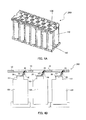
- FIG. 4A illustrates battery block 200 including one fuse board 100.
- Battery block 200 includes twenty cells 150 in total. One electrode of each cell 150 is connected to fuse board 100.
- FIG. 4B illustrates a cross-section of connection portions between fuse board 100 and cells 150 in battery block 200.
- electrode terminals 151 of cells 150 are connected to connection portions 20 of fuse board 100.
- This connection may be performed by welding. Vibration may occur during the welding, but a stress is hardly applied to fuse portions 30 of fuse board 100 and thus the wires of the fuse portions are not cut.
- the fuse board according to the present invention can be obtained simply and inexpensively by punching and bending a metal plate. The cutting of the fine metal wire of the fuse portion is suppressed. Accordingly, the fuse board can be used as a fuse board of a battery or a battery block including plural cells. The cells and the fuse board can be bonded to each other even by welding in which vibration easily occurs.
- the battery block including the fuse board according to the present invention hardly causes fuse cutting due to vibration. Therefore, the battery block according to the present invention can be suitably used in environments where vibration easily occurs, such as secondary batteries for vehicles.
Landscapes
- Engineering & Computer Science (AREA)
- Manufacturing & Machinery (AREA)
- Chemical & Material Sciences (AREA)
- Chemical Kinetics & Catalysis (AREA)
- Electrochemistry (AREA)
- General Chemical & Material Sciences (AREA)
- Microelectronics & Electronic Packaging (AREA)
- Power Engineering (AREA)
- Fuses (AREA)
- Connection Of Batteries Or Terminals (AREA)
- Battery Mounting, Suspending (AREA)
- Protection Of Static Devices (AREA)
- Charge And Discharge Circuits For Batteries Or The Like (AREA)
Abstract
Description
- The present invention relates to a fuse board and a battery block having the fuse board.
- A battery block having desired voltage or current capacity is obtained by combining plural cells. In the battery block, electrode terminals of the plural cells are connected to a single electrode plate. Therefore, when overcurrent flows in a cell, the battery block itself may be short-circuited. Therefore, a fuse for disconnecting the electrode plate and the corresponding cell may be provided to prevent a short circuit.
- When a fuse is disposed between the corresponding cell and the electrode plate, a technique of forming the fuse by performing a bracket welding process between an electrode terminal of a cell and an electrode plate or forming the fuse by wire-bonding has been proposed (see PTL 1).
PTL 2 discloses a fuse manufacturing method including (A) a step of forming an input terminal portion and plural output terminal portions by press-punching a conductive metal plate, (B) a step of previously molding an area of the punched metal plate, which includes a position where a fuse portion is formed, with an insulator, and (C) a step of forming the fuse portion having a substantially S shape through the use of a punching process. However, there is a problem in that the manufacturing process is complicated and bonding strength between the fuse and the cell is weak.
Various relevant techniques have been disclosed (for example, PTLs 3 to 7), but the above-mentioned problem has not been solved. -
- PTL 1
U.S. Patent No. 7,671,565 - PTL 2
Japanese Patent Application Laid-Open No.2001-160347 - PTL 3
Japanese Patent Application Laid-Open No.2005-347251 - PTL 4
International Publication No.WO2011/007535 - PTL 5
U.S. Patent Application Laid-Open No. 2003-0075352 - PTL 6
U.S. Patent Application Laid-Open No. 2005-0275370 - PTL 7
U.S. Patent Application Laid-Open No. 2007-0188147 - As described above, in the battery block including plural cells, a fuse is provided to each cell so as to prevent a short circuit of the battery block. However, the wire-bonding process is complicated and troublesome. On the other hand, when a fuse is intended to bond to an electrode terminal by welding, a wire of a fuse may be cut due to vibration in the welding process. When the battery block is actually being used, the wires of the fuses may be cut due to vibration.
- Particularly, when a fuse board formed by punching and bending a metal plate is welded to cells, wires of fuses are relatively bulky and thus can easily vibrate and be easily cut. Therefore, an object of the present invention is to prevent cutting of a fuse wire due to vibration by optimizing a wiring pattern of a fuse and forming a resin film for protecting the fuse.
- A first embodiment of the present invention is a fuse board to be described below.
- (1) A fuse board including a metal plate, a connection portion connected to a cell, a fuse portion connecting the metal plate to the connection portion, and an insulating resin film bonded to the fuse portion, wherein a wiring pattern of the fuse portion has bent portion, and the insulating resin film has a rectangular sheet-like shape that covers one surface of the fuse portion.
- (2) The fuse board according to (1), wherein the metal plate includes a suspension portion that is able to vibrate, and the fuse portion is connected to the suspension portion.
- (3) The fuse board according to (1), wherein the fuse board is obtained by punching and bending the metal plate to pattern the connection portion and the fuse portion.
- (4) The fuse board according to (1), wherein the height of the metal plate is different from the height of the connection portion.
- (5) The fuse board according to (1), wherein the wiring pattern of the fuse portion has two or more bent portions, and the two or more bent portions are located on the opposite sides about a straight line connecting both ends of the fuse portion.
- (6) The fuse board according to (1), wherein the thickness of the fuse portion is smaller than the thickness of the metal plate.
- (7) The fuse board according to (1), wherein the insulating resin film includes an insulating resin and an inorganic filler.
- (8) The fuse board according to (1), wherein the fuse board includes one metal plate, a plurality of connection portions, a plurality of fuse portions, and a plurality of insulating resin films.
- A second embodiment of the present invention is a fuse board manufacturing method to be described below.
- (9) A method of manufacturing the fuse board according to (1), including: preparing a metal plate; forming a connection portion and a fuse portion by punching the metal plate; adjusting the position of the connection portion by bending the metal plate; and covering the connection portion with an insulating resin film.
- A third embodiment of the present invention is a battery block to be described below.
- (10) A battery block including a plurality of cells having two or more electrode terminals and a fuse board connected to one electrode terminal of each of the plurality of cells, wherein the fuse board includes a metal plate, connection portions welded to one electrode terminal of each of the plurality of cells, fuse portions connecting the metal plate to the connection portions, and insulating resin films bonded to the fuse portions, and a wiring pattern of the fuse portion has a bent portion.
A fourth embodiment of the present invention is a fuse board to be described below. - (11) A fuse board including: a metal plate in which a plurality of openings extending from the top surface to the bottom surface are formed; a suspension portion that includes a first rod-like portion and a second rod-like portion extending from two points on the edge of each opening, respectively, and a body portion continuously extending from ends of the first rod-like portion and the second rod-like portion and that is formed in a substantial U-shape to be able to vibrate; a fuse portion that is formed from the body portion of the suspension portion to a joint to the metal plate to continuously extend from the suspension portion and that includes a bent wiring pattern; a connection portion that is formed continuously from the fuse portion and that is able to be connected to a corresponding cell; and an insulating resin film that has a rectangular sheet-like shape extending from a part of the body portion of the suspension portion to a part of the connection portion to cover one surface of the fuse portion.
- (12) The fuse board according to (11), wherein the top surface of the connection portion is disposed lower than the bottom surface of the metal plate.
- The fuse board according to the present invention can be simply and easily manufactured by punching and bending a metal plate. In the fuse board according to the present invention, the wire of the fuse portion is not easily cut even due to vibration or the like. Therefore, it is possible to prevent a fuse member from being cut due to vibration even in a welding process of bonding the fuse board to the battery or in the use of the battery.
- By disposing plural connection portions and fuse portions in the fuse board according to the present invention, a battery block in which a fuse function is given to each cell is provided as a battery block having plural cells. Therefore, even when a problem is caused in some cells, it is possible to prevent a short circuit of the battery block as a whole.
-
-
FIG. 1 is a top perspective view of a fuse board according to an embodiment; -
FIG. 2A is a top view of the fuse board according to the embodiment; -
FIG. 2B is a cross-sectional view of the fuse board according to the embodiment; -
FIG. 3A is a diagram illustrating a fuse pattern of the fuse board according to the embodiment (one example thereof); -
FIG. 3B is a diagram illustrating a fuse pattern of the fuse board according to the embodiment (another example thereof); -
FIG. 4A is a top perspective view of a battery block including the fuse board according to the embodiment; and -
FIG. 4B is a cross-sectional view of the battery block including the fuse board according to the embodiment. - Hereinafter, the invention will be described with reference to an embodiment but the invention is not limited to the invention. In the accompanying drawings, elements having equal or similar functions will be referenced by equal or similar reference numerals and description thereof will not be repeated. The drawings are schematic. Therefore, specific dimensions should be determined in comparison with the following description. The elements in the drawings may have different dimensional relationships or ratios.
- A fuse board according to the present invention includes a metal plate, a connection portion connected to a cell, a fuse portion, and an insulating resin film. Preferably, the fuse board according to the present invention includes two or more connection portions, fuse portions, and insulating resin films for each metal plate. The fuse board including the two or more connection portions, fuse portions, and insulating resin films can be used as a fuse board of a battery block including plural cells.
-
FIG. 1 is a top perspective view offuse board 100 according to an embodiment of the present invention.FIG. 2A is a top view offuse board 100.FIG. 2B is a cross-sectional view offuse board 100.
Fuse board 100 includes (A)metal plate 10 in whichplural openings 11 extending fromtop surface 10a tobottom surface 10b are formed, (B) substantiallyU-shaped suspension portion 40 that includes first rod-like portion 40a and second rod-like portion 40b extending from two points 11a and 11c on the edge of opening 11, respectively, and body portion 40b that is formed to continuously extend from ends of first rod-like portion 40a and second rod-like portion 40c and that is able to vibrate, (C)fuse portion 30 that includes a bent wiring pattern formed from body portion 40b ofsuspension portion 40 to joints 11a and 11c tometal plate 10 to continuously extend fromsuspension portion 40, (D)connection portion 20 that is formed to continuously extend fromfuse portion 30 and that is able to be connected to a cell, and (E) insulatingresin film 50 that extends from a part of body portion 40b ofsuspension portion 40 to a part ofconnection portion 20 to cover one surface offuse portion 30 and that has a rectangular sheet shape. - It is preferable that
top surface 20a ofconnection portion 20 be disposed lower by a distance D frombottom surface 10b ofmetal plate 10. Sincesuspension portion 30 is able to vibrate in the gravitational direction (in the Z direction in the drawing), a stress due to vibration in use can be absorbed. In this way, by providingsuspension portion 40 having a three-dimensional shape, it is possible to keep reliability of connection to a cell high according tofuse board 100.
Fuse portion 30 is protected by insulatingresin film 50, and thus is not easily cut even with a stress due to vibration. - In
fuse board 100, opening 11,suspension portion 40,fuse portion 30, andconnection portion 20 are patterned by punching and bending a metal plate. That is, sincefuse board 10 can be formed as a unified body out of a metal plate, it is possible to simply and easily manufacture the fuse board. - On the other hand, the fuse disclosed in PTL 2 has a planar shape obtained by press-punching a metal plate. The fuse disclosed in PTL 2 and the like does not include three-
dimensional suspension portion 40. Accordingly, the fuse disclosed in PTL 2 and the like cannot absorb the entire stress due to vibration in use and it is thus difficult to keep the reliability of connection to a cell high. - A metal plate of the fuse board is preferably a plate formed of metal. Examples of the metal include aluminum, stainless steel, copper, and brass, and aluminum can be preferably used. The thickness of the metal plate is not particularly limited, and may be in the range of about 0.15 to 3 mm. Within this range, mechanical strength as a member can be obtained.
- The connection portion of the fuse board is a metal member connected to an electrode terminal of a cell. Although not particularly limited, the connection portion is welded to the electrode terminal. It is preferable that metal forming the connection portion be the same as the metal plate. The thickness of the connection portion is not particularly limited, and may be in the range of 0.1 to 0.4 mm and preferably in the range of 0.2 to 0.25 mm. When the thickness is excessively large, it may be difficult to weld the connection portion to the electrode terminal of a cell.
- It is preferable that the connection portion be located at a height position different from the height of the metal plate. This is because the connection portion can be simply connected to the electrode terminal of a cell.
- The fuse portion is a fine metal wire and the line width thereof may be in the range of 0.1 to 0.4 mm. The thickness of the metal wire of the fuse portion is in the range of 0.1 to 0.4 mm and preferably in the range of 0.2 to 0.25 mm. It is preferable that the metal of the metal wire of the fuse portion be the same as the metal plate. When the line width of the metal wire of the fuse portion is excessively large or the thickness thereof is excessively large, it is not possible to obtain a fuse function (a function of cutting the metal wire when overcurrent flows).
- The metal wiring pattern of the fuse portion has a bent portion and preferably has so-called "flexure" (see
FIG. 3A and 3B ). Accordingly, the stress on the fuse portion is reduced and thus the fuse portion is not easily cut. The metal wiring pattern of the fuse portion has only to have a bent portion, and the degree of flexure t (seeFIG. 3A ) is preferably larger than the line width of the fuse pattern. It is preferable that the fuse pattern of the fuse portion have two or more bent portions (seeFIG. 3B ). It is preferable that the two bent portions be located on the opposite sides about a straight line (a straight line connecting a connecting position to the connection portion and a connecting position to the metal plate) connecting both ends of the fuse portion. By employing such a fuse pattern, it is possible to alleviate the stress even when the stress is applied in any direction. - The insulating resin film is a protective film protecting the fuse portion. As described above, since the fuse portion is a fine metal wire, the fuse portion can be easily cut due to vibration. Therefore, by attaching the insulating resin film to the fuse portion, it is preferable to prevent the cutting of the fuse portion. It is preferable that the insulating resin film be disposed to cover at least one surface of the fuse portion. From the viewpoint of improvement in workability or reliability of connection to a cell, it is preferable that the insulating resin film having a rectangular sheet shape extending from a part of the body portion of the suspension portion to a part of the connection portion be disposed to cover one surface of the fuse portion. This is because it is possible to achieve improvement in reliability of connection to a cell. Since only one positioning operation in the press-punching process on the metal plate is required, it is possible to simplify the manufacturing process.
On the other hand, as disclosed in PTL 2, when the punching process is performed so that the shape of the insulating resin film is matched with the shape of the fuse portion, it is difficult to effectively prevent the cutting of the fuse portion. In PTL 2, a process of forming an insulator in an area including the portion in which the fuse is formed is performed before the punching process on the metal plate. Accordingly, it is necessary to position punched portions for each process and thus the manufacturing process is complicated. - It is preferable that the insulating resin film include a resin component such as polyimide, an epoxy-based resin, and an acryl-based resin and an insulating inorganic filler. An example of the inorganic filler is a glass filler. The thickness of the insulating resin film is not particularly limited, and may be in the range of 50 µm to 500 µm.
- As described above, it is preferable that the fuse board include a suspension portion being able to vibrate. Since the suspension portion connects the metal plate and the fuse portion, the vibration of the fuse board is absorbed by the suspension portion and the stress due to vibration is not easily applied to the fuse portion. Specifically, the suspension portion is, for example, a U-shaped member and both ends are supported by the metal plate. The fuse portion is connected to the central portion of the U shape.
- The volume of the metal forming the suspension portion is larger than the volume of the metal forming the fuse portion. Accordingly, the suspension portion absorbs the vibration of the fuse board to suppress application of a stress to the fuse portion.
- The fuse board according to the present invention can be manufactured by punching and bending a base metal plate. Specifically, by punching the base metal plate, the connection portions, the fuse portions, and the suspension portions constituting the fuse board are formed. As a result, the base metal plate becomes a metal plate constituting the fuse board. The metal of the connection portions, the fuse portions, and the suspension portions is the same metal as the metal plate constituting the fuse board.
- It is preferable that portions of the metal plate which become the connection portions, the fuse portions, and the suspension portions be compressed to reduce the thickness before performing the punching process. After the compression, members corresponding to the connection portions and the fuse portions are punched to form shapes.
- The connection portions are subjected to a bending process so as to easily connect the connection portions to cells. Specifically, the height of the metal plate and the height of the connection portions are made to be different from each other. By bending the connection portions in a predetermined shape and then attaching the insulating resin films to the fuse portions, a fuse board is obtained.
- The battery block according to the present invention includes the fuse board according to the embodiment of the present invention and plural cells. Each of the plural cells has a pair of electrode terminals. The connection portion of the fuse board is connected to one electrode terminal of each of the plural cells. This connection can be performed by welding.
- The battery block may include plural cells and a member housing the plural cells. The member housing the cells is not particularly limited, but may be a member which is obtained by unifying plural pipe-like members and which can house the cells in the respective pipe-like members.
- The present invention will be described below with reference to the accompanying drawings.
FIG. 1 is a top perspective view offuse board 100 according to an embodiment.Fuse board 100 includesmetal plate 10 and twentyfuse function portions 90. Eachfuse function portion 90 includesconnection portion 20,fuse portion 30,suspension portion 40, and insulating resin film 50 (seeFIGS. 2A and 2B ). - PIG. 2A is a top view of
fuse board 100 according to the embodiment. As illustrated inFIG. 2A ,connection portion 20,fuse portion 30, insulatingresin film 50, andsuspension portion 40 are formed inmetal plate 10.Suspension portion 40 has a U shape, and both ends of the U shape are fixed to and supported bymetal plate 10. One end offuse portion 30 is connected to the central portion of the U shape. The other end offuse portion 30 is connected toconnection portion 20. -
FIG. 2B is a cross-sectional view taken along line X-X offuse board 100. As illustrated inFIG. 2B , the thickness ofconnection portion 20,fuse portion 30, andsuspension portion 40 is smaller than the thickness ofmetal plate 10. By reducing the thickness of the connection portion, the welding thereof to the electrode terminal of the corresponding cell is facilitated. By reducing the thickness offuse portion 30, a fuse function is obtained. As illustrated inFIG. 2B , the height ofmetal plate 10 is different from the height ofconnection portion 20. By causing the heights to be different from each other, it is easy to connectconnection portion 20 to the electrode terminal of the corresponding cell (seeFIG. 4 ). - When
fuse board 100 vibrates,U-shaped suspension portion 40 absorbs the vibration. Accordingly, a stress due to the vibration is hardly applied to fuseportion 30 connected tosuspension portion 40. Sincefuse portion 30 is protected by insulatingresin film 50, the fuse portion is not easily cut even with a stress due to vibration applied thereto. -
FIGS. 3A and 3B illustrate examples of the metal wiring pattern offuse portion 30 offuse board 100. The wiring pattern offuse portion 30 illustrated inFIG. 3A has bentportion 31. By providingbent portion 31, the metal wire offuse portion 30 has a flexure and a stress is hardly applied to the metal wire. The degree of flexure t has only to be larger than the width of the wire. -
Fuse portion 30 illustrated inFIG. 3B has first bentportion 31 and secondbent portion 32. By providing two bent portions, flexures are formed in the metal wire offuse portion 30 and thus the stress load due to vibration is more easily alleviated. Particularly, as illustrated inFIG. 3B , when firstbent portion 31 and secondbent portion 32 are located on the opposite side about a straight line connecting a joint offuse portion 30 toconnection portion 20 and a joint tosuspension portion 40, it is easier to alleviate the stress. -
FIG. 4A illustratesbattery block 200 including onefuse board 100.Battery block 200 includes twentycells 150 in total. One electrode of eachcell 150 is connected to fuseboard 100. -
FIG. 4B illustrates a cross-section of connection portions betweenfuse board 100 andcells 150 inbattery block 200. As illustrated inFIG. 4B ,electrode terminals 151 ofcells 150 are connected toconnection portions 20 offuse board 100. This connection may be performed by welding. Vibration may occur during the welding, but a stress is hardly applied to fuseportions 30 offuse board 100 and thus the wires of the fuse portions are not cut. - When a problem occurs in
cell 150 and overcurrent flows inbattery block 200, the wires ofseveral fuse portions 30 offuse board 100 are cut. Therefore,battery block 200 does not cause a short circuit.
The disclosures of Japanese Patent Applications previously filed by the applicant of the present invention, that is, Japanese Patent Application No.2011-121643 (filed on May 31, 2011 2011-181891 (filed on August 23, 2011 - The fuse board according to the present invention can be obtained simply and inexpensively by punching and bending a metal plate. The cutting of the fine metal wire of the fuse portion is suppressed. Accordingly, the fuse board can be used as a fuse board of a battery or a battery block including plural cells. The cells and the fuse board can be bonded to each other even by welding in which vibration easily occurs.
- The battery block including the fuse board according to the present invention hardly causes fuse cutting due to vibration. Therefore, the battery block according to the present invention can be suitably used in environments where vibration easily occurs, such as secondary batteries for vehicles.
-
Reference Signs List 10 Metal Plate 11 Opening 20 Connection portion 30 Fuse portion 31 First bent portion 32 Second bent portion 40 Suspension portion 50 Insulating resin film 90 Fuse junction portion 100 Fuse board 150 Cell 151 Electrode terminal 200 Battery block
Claims (12)
- A fuse board comprising a metal plate, a connection portion connected to a cell, a fuse portion connecting the metal plate to the connection portion, and an insulating resin film bonded to the fuse portion,
wherein a wiring pattern of the fuse portion has bent portion, and
wherein the insulating resin film has a rectangular sheet-like shape that covers one surface of the fuse portion. - The fuse board according to claim 1, wherein the metal plate includes a suspension portion that is able to vibrate, and
wherein the fuse portion is connected to the suspension portion. - The fuse board according to claim 1, wherein the fuse board is obtained by punching and bending the metal plate to pattern the connection portion and the fuse portion.
- The fuse board according to claim 1, wherein the height of the metal plate is different from the height of the connection portion.
- The fuse board according to claim 1, wherein the wiring pattern of the fuse portion has two or more bent portions, and
wherein the two or more bent portions are located on the opposite sides about a straight line connecting both ends of the fuse portion. - The fuse board according to claim 1, wherein the thickness of the fuse portion is smaller than the thickness of the metal plate,
- The fuse board according to claim 1, wherein the insulating resin film includes an insulating resin and an inorganic filler.
- The fuse board according to claim 1, wherein the fuse board includes one metal plate, a plurality of connection portions, a plurality of fuse portions, and a plurality of insulating resin films.
- A method of manufacturing the fuse board according to claim 1, comprising:preparing a metal plate;forming a connection portion and a fuse portion by punching the metal plate;adjusting the position of the connection portion by bending the metal plate; andcovering the connection portion with an insulating resin film.
- A battery block comprising a plurality of cells having two or more electrode terminals and a fuse board connected to one electrode terminal of each of the plurality of cells,
wherein the fuse board includes a metal plate, connection portions welded to one electrode terminal of each of the plurality of cells, fuse portions connecting the metal plate to the connection portions, and insulating resin films bonded to the fuse portions, and
wherein a wiring pattern of the fuse portion has a bent portion. - A fuse board comprising:a metal plate in which a plurality of openings extending from the top surface to the bottom surface are formed;a suspension portion that includes a first rod-like portion and a second rod-like portion extending from two points on the edge of each opening, respectively, and a body portion continuously extending from ends of the first rod-like portion and the second rod-like portion and that is formed in a substantial U-shape to be able to vibrate;a fuse portion that is formed from the body portion of the suspension portion to a joint to the metal plate to continuously extend from the suspension portion and that includes a bent wiring pattern;a connection portion that is formed continuously from the fuse portion and that is able to be connected to a corresponding cell; andan insulating resin film that has a rectangular sheet-like shape extending from a part of the body portion of the suspension portion to a part of the connection portion to cover one surface of the fuse portion.
- The fuse board according to claim 11, wherein the top surface of the connection portion is disposed lower than the bottom surface of the metal plate,
Applications Claiming Priority (3)
| Application Number | Priority Date | Filing Date | Title |
|---|---|---|---|
| JP2011121643 | 2011-05-31 | ||
| JP2011181891 | 2011-08-23 | ||
| PCT/JP2012/003412 WO2012164884A1 (en) | 2011-05-31 | 2012-05-25 | Fuse board and battery block equipped with same |
Publications (3)
| Publication Number | Publication Date |
|---|---|
| EP2608243A1 true EP2608243A1 (en) | 2013-06-26 |
| EP2608243A4 EP2608243A4 (en) | 2014-08-13 |
| EP2608243B1 EP2608243B1 (en) | 2015-12-30 |
Family
ID=47258761
Family Applications (1)
| Application Number | Title | Priority Date | Filing Date |
|---|---|---|---|
| EP12792387.8A Not-in-force EP2608243B1 (en) | 2011-05-31 | 2012-05-25 | Fuse board and battery block equipped with same |
Country Status (6)
| Country | Link |
|---|---|
| US (1) | US10566165B2 (en) |
| EP (1) | EP2608243B1 (en) |
| JP (3) | JP5185474B2 (en) |
| KR (1) | KR101432459B1 (en) |
| CN (1) | CN103140912B (en) |
| WO (1) | WO2012164884A1 (en) |
Cited By (16)
| Publication number | Priority date | Publication date | Assignee | Title |
|---|---|---|---|---|
| EP2955738A4 (en) * | 2013-02-08 | 2016-04-20 | Toyota Motor Co Ltd | CONNECTING ELEMENT |
| WO2017088996A1 (en) | 2015-11-24 | 2017-06-01 | Nordfels Gmbh | Busbar and battery module having such a busbar |
| WO2017222640A1 (en) * | 2016-06-20 | 2017-12-28 | Cooper Technologies Company | High voltage power fuse including fatigue resistant fuse element |
| EP3282501A1 (en) | 2016-08-08 | 2018-02-14 | Nordfels GmbH | Battery, battery module for the battery and bus bar for same |
| US9989579B2 (en) | 2016-06-20 | 2018-06-05 | Eaton Intelligent Power Limited | Monitoring systems and methods for detecting thermal-mechanical strain fatigue in an electrical fuse |
| EP3496180A1 (en) * | 2017-12-08 | 2019-06-12 | Atnom S.R.L. | Ultra-lightweight fireproof battery assembly with passive cooling and optional active temperature control |
| EP3633764A4 (en) * | 2017-05-29 | 2020-06-17 | Sanyo Electric Co., Ltd. | BATTERY PACK |
| WO2021113891A1 (en) * | 2019-12-13 | 2021-06-17 | Kreisel Electric Gmbh & Co Kg | Device for breaking the electrical connection to a battery cell in the event of outgassing |
| EP3843177A1 (en) * | 2019-12-23 | 2021-06-30 | Dae San Electronics Co., Ltd. | Busbar to which fuse has been applied |
| US11143718B2 (en) | 2018-05-31 | 2021-10-12 | Eaton Intelligent Power Limited | Monitoring systems and methods for estimating thermal-mechanical fatigue in an electrical fuse |
| DE102020110813A1 (en) | 2020-04-21 | 2021-10-21 | Bayerische Motoren Werke Aktiengesellschaft | Electrical energy store for a motor vehicle, motor vehicle and method for producing such an electrical energy store |
| US11289298B2 (en) | 2018-05-31 | 2022-03-29 | Eaton Intelligent Power Limited | Monitoring systems and methods for estimating thermal-mechanical fatigue in an electrical fuse |
| EP4087050A4 (en) * | 2019-12-30 | 2024-05-29 | Hefei Gotion High-Tech Power Energy Co., Ltd. | Integrated high-temperature decomposable connector and lithium ion battery comprising same |
| EP4087048A4 (en) * | 2019-12-30 | 2024-05-29 | Hefei Guoxuan High-Tech Power Energy Co., Ltd. | EXTERNAL SHORT CIRCUIT PROTECTION DEVICE FOR LITHIUM ION BATTERY |
| EP3295497B1 (en) * | 2015-05-11 | 2024-06-26 | Gogoro Inc. | Electrical connector for portable multi-cell electrical energy storage device |
| EP4664658A1 (en) * | 2024-06-14 | 2025-12-17 | fischer Power Solutions GmbH | Cell connector for electrical cells |
Families Citing this family (28)
| Publication number | Priority date | Publication date | Assignee | Title |
|---|---|---|---|---|
| JP6018937B2 (en) | 2013-01-29 | 2016-11-02 | 三洋電機株式会社 | Electrode member and battery block |
| KR101696010B1 (en) | 2013-06-19 | 2017-01-12 | 삼성에스디아이 주식회사 | Rechargeable battery |
| JP6229903B2 (en) | 2013-10-31 | 2017-11-15 | パナソニックIpマネジメント株式会社 | Battery module |
| JP2015135869A (en) * | 2014-01-16 | 2015-07-27 | 株式会社テラプローブ | Semiconductor device and manufacturing method of semiconductor device |
| JP6492668B2 (en) * | 2014-01-23 | 2019-04-03 | 株式会社村田製作所 | Power storage device, power storage system, electronic device, electric vehicle, and power system |
| JP6216254B2 (en) * | 2014-01-28 | 2017-10-18 | ダイキョーニシカワ株式会社 | Battery module |
| JP6211425B2 (en) * | 2014-01-28 | 2017-10-11 | ダイキョーニシカワ株式会社 | Battery module |
| JP6282125B2 (en) * | 2014-01-31 | 2018-02-21 | ダイキョーニシカワ株式会社 | Battery module |
| KR102172843B1 (en) * | 2014-03-20 | 2020-11-02 | 삼성에스디아이 주식회사 | Secondary Battery |
| KR102248595B1 (en) | 2014-04-15 | 2021-05-06 | 삼성에스디아이 주식회사 | Secondary Battery |
| WO2016062250A1 (en) | 2014-10-23 | 2016-04-28 | Quantum Force Engineering Limited | Battery assembly |
| JP6775109B2 (en) * | 2014-11-04 | 2020-10-28 | パナソニックIpマネジメント株式会社 | Electrode member, current collector plate, battery block |
| US9966586B2 (en) * | 2015-12-30 | 2018-05-08 | Thunder Power New Energy Vehicle Development Company Limited | Integrated busbar and battery connection for electric vehicle battery packs |
| WO2018055677A1 (en) * | 2016-09-20 | 2018-03-29 | 株式会社東芝 | Battery assembly and electroconductive member |
| WO2018055676A1 (en) * | 2016-09-20 | 2018-03-29 | 株式会社東芝 | Battery pack and electrically conductive member |
| CN116435672A (en) * | 2017-09-20 | 2023-07-14 | 松下知识产权经营株式会社 | battery module |
| KR102410972B1 (en) * | 2017-09-22 | 2022-06-20 | 삼성에스디아이 주식회사 | Battery pack |
| KR102350459B1 (en) | 2017-12-07 | 2022-01-11 | 주식회사 엘지에너지솔루션 | Cylindrical secondary battery module |
| KR102505612B1 (en) * | 2018-01-31 | 2023-03-03 | 삼성에스디아이 주식회사 | Battery pack |
| KR102259380B1 (en) | 2018-04-20 | 2021-06-01 | 주식회사 엘지에너지솔루션 | Battery Module Having Bus-bar and Battery Pack |
| US20200091493A1 (en) * | 2018-09-19 | 2020-03-19 | Tiveni Mergeco, Inc. | Battery module including coated or clad material contact plate |
| US11108119B2 (en) * | 2018-10-26 | 2021-08-31 | The Boeing Company | Fusible link design for lithium-ion 18650 cells |
| KR102757688B1 (en) * | 2019-01-28 | 2025-01-21 | 삼성에스디아이 주식회사 | Battery Pack |
| EP4358654A3 (en) * | 2019-03-28 | 2024-12-04 | CPS Technology Holdings LLC | Flexible circuit having a fuse, bus bar holder including a lead-in structure, electrical conduction assembly having a bus bar, and battery including the same |
| KR102789615B1 (en) | 2019-05-08 | 2025-03-31 | 주식회사 엘지에너지솔루션 | Connecting Member for Connecting a Plurality of Cells in series and Cylindrical Battery Cell Structure |
| KR102820678B1 (en) | 2019-09-24 | 2025-06-12 | 주식회사 엘지에너지솔루션 | Battery Module Comprising Busbar Plate and Battery Pack Having the Same and Electric Device |
| KR102873394B1 (en) | 2019-12-04 | 2025-10-17 | 주식회사 엘지에너지솔루션 | Battery Module and Battery Pack |
| KR20250034758A (en) * | 2023-09-04 | 2025-03-11 | 삼성에스디아이 주식회사 | Rechargeable battery module |
Family Cites Families (27)
| Publication number | Priority date | Publication date | Assignee | Title |
|---|---|---|---|---|
| JPS55137505U (en) * | 1979-03-20 | 1980-09-30 | ||
| DE3040884C2 (en) | 1980-10-30 | 1986-09-25 | Hermann Stribel KG, 7443 Frickenhausen | Protection scheme |
| JPH05266871A (en) * | 1991-04-23 | 1993-10-15 | Ryoden Kasei Co Ltd | Attachment structure for connection terminal of battery electrode of mobile device |
| US5204194A (en) | 1992-05-21 | 1993-04-20 | Magnavox Electronic Systems Company | Multicell battery having a tab-fuse for overcurrent interruption |
| JPH07254347A (en) | 1994-03-16 | 1995-10-03 | Asahi Denki Seisakusho:Kk | Fast-acting current limiting fuse with large capacity rated current value |
| US5644282A (en) * | 1995-02-06 | 1997-07-01 | Motorola, Inc. | Fuse and Battery apparatus utilizing same |
| US5805423A (en) * | 1996-05-17 | 1998-09-08 | United Technologies Automotive | Battery contact and retention apparatus for printed circuit boards |
| US6342826B1 (en) * | 1999-08-11 | 2002-01-29 | Therm-O-Disc, Incorporated | Pressure and temperature responsive switch assembly |
| JP3814451B2 (en) | 1999-12-03 | 2006-08-30 | 住友電装株式会社 | Manufacturing method of fuse |
| JP3740116B2 (en) * | 2002-11-11 | 2006-02-01 | 三菱電機株式会社 | Molded resin encapsulated power semiconductor device and manufacturing method thereof |
| JP4576794B2 (en) * | 2003-02-18 | 2010-11-10 | 日立化成工業株式会社 | Insulating resin composition and use thereof |
| KR100571231B1 (en) | 2004-05-31 | 2006-04-13 | 삼성에스디아이 주식회사 | Fuse device of lithium ion battery |
| TWI294193B (en) * | 2005-12-06 | 2008-03-01 | Giga Byte Tech Co Ltd | Battery holder structure with jumper |
| KR100719723B1 (en) * | 2005-12-29 | 2007-05-17 | 삼성에스디아이 주식회사 | Conductive plate and pack battery using same |
| US7671565B2 (en) | 2006-02-13 | 2010-03-02 | Tesla Motors, Inc. | Battery pack and method for protecting batteries |
| KR20080025437A (en) | 2006-09-18 | 2008-03-21 | 주식회사 엘지화학 | Secondary battery that can adjust position of electrode terminal and improve safety |
| WO2008098193A2 (en) * | 2007-02-09 | 2008-08-14 | Johnson Controls--Saft Advanced Power Solutions Llc | Buss bar for batteries |
| US7923144B2 (en) * | 2007-03-31 | 2011-04-12 | Tesla Motors, Inc. | Tunable frangible battery pack system |
| CN101836310B (en) * | 2007-07-16 | 2013-03-27 | 株式会社Lg化学 | Electrical connection member for secondary battery |
| GB0806190D0 (en) * | 2008-04-04 | 2008-05-14 | Obrist Closures Switzerland | A closure |
| US20100291426A1 (en) * | 2009-05-15 | 2010-11-18 | Sinoelectric Powertrain Corporation | Flexible fusible link, systems, and methods |
| US9104629B2 (en) * | 2009-07-09 | 2015-08-11 | International Business Machines Corporation | Autonomic reclamation processing on sequential storage media |
| EP2339669B1 (en) | 2009-07-17 | 2013-03-13 | Panasonic Corporation | Battery connecting member and battery module using same |
| JP2011121643A (en) | 2009-12-12 | 2011-06-23 | Mitsuru Nozaki | Method for binding dried noodle |
| JP2011181891A (en) | 2010-02-08 | 2011-09-15 | Toshiba Corp | Nonvolatile semiconductor memory device |
| US8361646B2 (en) * | 2010-03-15 | 2013-01-29 | Electronvault, Inc. | Modular interconnection system |
| JP6018937B2 (en) * | 2013-01-29 | 2016-11-02 | 三洋電機株式会社 | Electrode member and battery block |
-
2012
- 2012-05-25 WO PCT/JP2012/003412 patent/WO2012164884A1/en not_active Ceased
- 2012-05-25 US US13/880,282 patent/US10566165B2/en active Active
- 2012-05-25 JP JP2012549581A patent/JP5185474B2/en active Active
- 2012-05-25 CN CN201280003183.1A patent/CN103140912B/en active Active
- 2012-05-25 EP EP12792387.8A patent/EP2608243B1/en not_active Not-in-force
- 2012-05-25 KR KR1020137007918A patent/KR101432459B1/en active Active
-
2013
- 2013-01-17 JP JP2013006693A patent/JP5314806B2/en active Active
- 2013-07-02 JP JP2013138652A patent/JP5360329B2/en active Active
Cited By (24)
| Publication number | Priority date | Publication date | Assignee | Title |
|---|---|---|---|---|
| EP2955738A4 (en) * | 2013-02-08 | 2016-04-20 | Toyota Motor Co Ltd | CONNECTING ELEMENT |
| EP3295497B1 (en) * | 2015-05-11 | 2024-06-26 | Gogoro Inc. | Electrical connector for portable multi-cell electrical energy storage device |
| US10770708B2 (en) | 2015-11-24 | 2020-09-08 | Voltlabor Gmbh | Busbar and battery module having such a busbar |
| WO2017088996A1 (en) | 2015-11-24 | 2017-06-01 | Nordfels Gmbh | Busbar and battery module having such a busbar |
| US10978267B2 (en) | 2016-06-20 | 2021-04-13 | Eaton Intelligent Power Limited | High voltage power fuse including fatigue resistant fuse element and methods of making the same |
| CN109314022A (en) * | 2016-06-20 | 2019-02-05 | 伊顿智能动力有限公司 | High voltage power fuses incorporating anti-fatigue fuse elements |
| US10254329B2 (en) | 2016-06-20 | 2019-04-09 | Eaton Intelligent Power Limited | Monitoring systems and methods for detecting thermal-mechanical strain fatigue in an electrical fuse |
| US9989579B2 (en) | 2016-06-20 | 2018-06-05 | Eaton Intelligent Power Limited | Monitoring systems and methods for detecting thermal-mechanical strain fatigue in an electrical fuse |
| WO2017222640A1 (en) * | 2016-06-20 | 2017-12-28 | Cooper Technologies Company | High voltage power fuse including fatigue resistant fuse element |
| WO2018029224A1 (en) | 2016-08-08 | 2018-02-15 | Nordfels Gmbh | Battery, battery module for the battery, and bus bar therefor |
| US10916757B2 (en) | 2016-08-08 | 2021-02-09 | Voltlabor Gmbh | Battery, battery module for the battery, and bus bar therefor |
| EP3282501A1 (en) | 2016-08-08 | 2018-02-14 | Nordfels GmbH | Battery, battery module for the battery and bus bar for same |
| EP3633764A4 (en) * | 2017-05-29 | 2020-06-17 | Sanyo Electric Co., Ltd. | BATTERY PACK |
| EP3496180A1 (en) * | 2017-12-08 | 2019-06-12 | Atnom S.R.L. | Ultra-lightweight fireproof battery assembly with passive cooling and optional active temperature control |
| US11289298B2 (en) | 2018-05-31 | 2022-03-29 | Eaton Intelligent Power Limited | Monitoring systems and methods for estimating thermal-mechanical fatigue in an electrical fuse |
| US11143718B2 (en) | 2018-05-31 | 2021-10-12 | Eaton Intelligent Power Limited | Monitoring systems and methods for estimating thermal-mechanical fatigue in an electrical fuse |
| WO2021113891A1 (en) * | 2019-12-13 | 2021-06-17 | Kreisel Electric Gmbh & Co Kg | Device for breaking the electrical connection to a battery cell in the event of outgassing |
| US12394873B2 (en) | 2019-12-13 | 2025-08-19 | John Deere Electric Powertrain Llc | Device for breaking the electrical connection to a battery cell in the event of outgassing |
| EP3843177A1 (en) * | 2019-12-23 | 2021-06-30 | Dae San Electronics Co., Ltd. | Busbar to which fuse has been applied |
| EP4087050A4 (en) * | 2019-12-30 | 2024-05-29 | Hefei Gotion High-Tech Power Energy Co., Ltd. | Integrated high-temperature decomposable connector and lithium ion battery comprising same |
| EP4087048A4 (en) * | 2019-12-30 | 2024-05-29 | Hefei Guoxuan High-Tech Power Energy Co., Ltd. | EXTERNAL SHORT CIRCUIT PROTECTION DEVICE FOR LITHIUM ION BATTERY |
| WO2021213748A1 (en) | 2020-04-21 | 2021-10-28 | Bayerische Motoren Werke Aktiengesellschaft | Electrical energy store for a motor vehicle, motor vehicle, and method for the production thereof |
| DE102020110813A1 (en) | 2020-04-21 | 2021-10-21 | Bayerische Motoren Werke Aktiengesellschaft | Electrical energy store for a motor vehicle, motor vehicle and method for producing such an electrical energy store |
| EP4664658A1 (en) * | 2024-06-14 | 2025-12-17 | fischer Power Solutions GmbH | Cell connector for electrical cells |
Also Published As
| Publication number | Publication date |
|---|---|
| JP5185474B2 (en) | 2013-04-17 |
| US10566165B2 (en) | 2020-02-18 |
| JP2013219052A (en) | 2013-10-24 |
| KR101432459B1 (en) | 2014-08-20 |
| CN103140912B (en) | 2015-07-22 |
| WO2012164884A1 (en) | 2012-12-06 |
| EP2608243A4 (en) | 2014-08-13 |
| JP5314806B2 (en) | 2013-10-16 |
| CN103140912A (en) | 2013-06-05 |
| JPWO2012164884A1 (en) | 2015-02-23 |
| KR20130081285A (en) | 2013-07-16 |
| US20130202941A1 (en) | 2013-08-08 |
| JP5360329B2 (en) | 2013-12-04 |
| EP2608243B1 (en) | 2015-12-30 |
| JP2013127973A (en) | 2013-06-27 |
Similar Documents
| Publication | Publication Date | Title |
|---|---|---|
| US10566165B2 (en) | Fuse board and battery block equipped with same | |
| JP5159233B2 (en) | Bus bar | |
| JP5715766B2 (en) | Wiring material connection structure | |
| US8721367B2 (en) | Fuse unit | |
| US9685650B2 (en) | Electric storage device including current interruption device | |
| KR102032506B1 (en) | Secondary battery module improved in connecting structure of sensing wire harness and assembly method for the same | |
| JP6177352B2 (en) | Battery wiring module | |
| US8859122B2 (en) | Interconnect device for battery assembly | |
| JP6346017B2 (en) | Bus bar module and method of manufacturing bus bar module | |
| US20140198470A1 (en) | Printed circuit board stack | |
| EP2738837A2 (en) | Battery module comprising an interlinking member having a vibration-damping portion | |
| JP6202338B2 (en) | Wiring module, wiring module intermediate, and wiring module manufacturing method | |
| JP6150904B2 (en) | Manufacturing method of battery wiring module | |
| JP2013101993A (en) | Semiconductor device | |
| JP4737664B2 (en) | Surface mount type solid electrolytic capacitor and manufacturing method thereof | |
| JP2005353709A (en) | Chip solid electrolytic capacitor and its manufacturing process | |
| CN220830008U (en) | Sampling member and battery | |
| JP2001286028A (en) | Method of manufacturing large-sized bus bar | |
| CN118117264A (en) | Laminated conductor | |
| CN115053316A (en) | Fuse and method for manufacturing fuse | |
| JP2025130104A (en) | Fuse device | |
| JP4675653B2 (en) | Semiconductor module manufacturing method and semiconductor module | |
| JP2015107046A (en) | Bus bar | |
| JP2013048150A (en) | Semiconductor module and manufacturing method of the same | |
| WO2016021123A1 (en) | Electronic circuit component |
Legal Events
| Date | Code | Title | Description |
|---|---|---|---|
| PUAI | Public reference made under article 153(3) epc to a published international application that has entered the european phase |
Free format text: ORIGINAL CODE: 0009012 |
|
| 17P | Request for examination filed |
Effective date: 20130319 |
|
| AK | Designated contracting states |
Kind code of ref document: A1 Designated state(s): AL AT BE BG CH CY CZ DE DK EE ES FI FR GB GR HR HU IE IS IT LI LT LU LV MC MK MT NL NO PL PT RO RS SE SI SK SM TR |
|
| A4 | Supplementary search report drawn up and despatched |
Effective date: 20140714 |
|
| RIC1 | Information provided on ipc code assigned before grant |
Ipc: H01H 85/12 20060101ALI20140708BHEP Ipc: H01H 85/00 20060101ALI20140708BHEP Ipc: H02J 7/00 20060101ALI20140708BHEP Ipc: H01M 2/30 20060101ALI20140708BHEP Ipc: H01M 2/34 20060101ALI20140708BHEP Ipc: H01H 85/143 20060101ALI20140708BHEP Ipc: H01H 85/08 20060101AFI20140708BHEP Ipc: H01M 2/10 20060101ALI20140708BHEP Ipc: H01H 69/02 20060101ALI20140708BHEP |
|
| DAX | Request for extension of the european patent (deleted) | ||
| RAP1 | Party data changed (applicant data changed or rights of an application transferred) |
Owner name: PANASONIC INTELLECTUAL PROPERTY MANAGEMENT CO., LT |
|
| RIC1 | Information provided on ipc code assigned before grant |
Ipc: H01H 85/08 20060101AFI20150518BHEP Ipc: H01M 2/10 20060101ALI20150518BHEP Ipc: H01H 85/00 20060101ALI20150518BHEP Ipc: H01H 85/12 20060101ALI20150518BHEP Ipc: H01H 69/02 20060101ALI20150518BHEP Ipc: H01M 2/30 20060101ALI20150518BHEP Ipc: H01H 85/143 20060101ALI20150518BHEP Ipc: H02J 7/00 20060101ALI20150518BHEP Ipc: H01M 2/34 20060101ALI20150518BHEP |
|
| GRAP | Despatch of communication of intention to grant a patent |
Free format text: ORIGINAL CODE: EPIDOSNIGR1 |
|
| INTG | Intention to grant announced |
Effective date: 20150805 |
|
| GRAS | Grant fee paid |
Free format text: ORIGINAL CODE: EPIDOSNIGR3 |
|
| GRAA | (expected) grant |
Free format text: ORIGINAL CODE: 0009210 |
|
| AK | Designated contracting states |
Kind code of ref document: B1 Designated state(s): AL AT BE BG CH CY CZ DE DK EE ES FI FR GB GR HR HU IE IS IT LI LT LU LV MC MK MT NL NO PL PT RO RS SE SI SK SM TR |
|
| REG | Reference to a national code |
Ref country code: GB Ref legal event code: FG4D |
|
| REG | Reference to a national code |
Ref country code: CH Ref legal event code: EP |
|
| REG | Reference to a national code |
Ref country code: AT Ref legal event code: REF Ref document number: 767818 Country of ref document: AT Kind code of ref document: T Effective date: 20160115 |
|
| REG | Reference to a national code |
Ref country code: IE Ref legal event code: FG4D |
|
| REG | Reference to a national code |
Ref country code: DE Ref legal event code: R096 Ref document number: 602012013509 Country of ref document: DE |
|
| REG | Reference to a national code |
Ref country code: LT Ref legal event code: MG4D |
|
| PG25 | Lapsed in a contracting state [announced via postgrant information from national office to epo] |
Ref country code: LT Free format text: LAPSE BECAUSE OF FAILURE TO SUBMIT A TRANSLATION OF THE DESCRIPTION OR TO PAY THE FEE WITHIN THE PRESCRIBED TIME-LIMIT Effective date: 20151230 Ref country code: HR Free format text: LAPSE BECAUSE OF FAILURE TO SUBMIT A TRANSLATION OF THE DESCRIPTION OR TO PAY THE FEE WITHIN THE PRESCRIBED TIME-LIMIT Effective date: 20151230 Ref country code: NO Free format text: LAPSE BECAUSE OF FAILURE TO SUBMIT A TRANSLATION OF THE DESCRIPTION OR TO PAY THE FEE WITHIN THE PRESCRIBED TIME-LIMIT Effective date: 20160330 |
|
| REG | Reference to a national code |
Ref country code: NL Ref legal event code: MP Effective date: 20151230 |
|
| REG | Reference to a national code |
Ref country code: AT Ref legal event code: MK05 Ref document number: 767818 Country of ref document: AT Kind code of ref document: T Effective date: 20151230 |
|
| REG | Reference to a national code |
Ref country code: FR Ref legal event code: PLFP Year of fee payment: 5 |
|
| PG25 | Lapsed in a contracting state [announced via postgrant information from national office to epo] |
Ref country code: SE Free format text: LAPSE BECAUSE OF FAILURE TO SUBMIT A TRANSLATION OF THE DESCRIPTION OR TO PAY THE FEE WITHIN THE PRESCRIBED TIME-LIMIT Effective date: 20151230 Ref country code: RS Free format text: LAPSE BECAUSE OF FAILURE TO SUBMIT A TRANSLATION OF THE DESCRIPTION OR TO PAY THE FEE WITHIN THE PRESCRIBED TIME-LIMIT Effective date: 20151230 Ref country code: LV Free format text: LAPSE BECAUSE OF FAILURE TO SUBMIT A TRANSLATION OF THE DESCRIPTION OR TO PAY THE FEE WITHIN THE PRESCRIBED TIME-LIMIT Effective date: 20151230 Ref country code: GR Free format text: LAPSE BECAUSE OF FAILURE TO SUBMIT A TRANSLATION OF THE DESCRIPTION OR TO PAY THE FEE WITHIN THE PRESCRIBED TIME-LIMIT Effective date: 20160331 Ref country code: FI Free format text: LAPSE BECAUSE OF FAILURE TO SUBMIT A TRANSLATION OF THE DESCRIPTION OR TO PAY THE FEE WITHIN THE PRESCRIBED TIME-LIMIT Effective date: 20151230 |
|
| PG25 | Lapsed in a contracting state [announced via postgrant information from national office to epo] |
Ref country code: NL Free format text: LAPSE BECAUSE OF FAILURE TO SUBMIT A TRANSLATION OF THE DESCRIPTION OR TO PAY THE FEE WITHIN THE PRESCRIBED TIME-LIMIT Effective date: 20151230 |
|
| PG25 | Lapsed in a contracting state [announced via postgrant information from national office to epo] |
Ref country code: CZ Free format text: LAPSE BECAUSE OF FAILURE TO SUBMIT A TRANSLATION OF THE DESCRIPTION OR TO PAY THE FEE WITHIN THE PRESCRIBED TIME-LIMIT Effective date: 20151230 Ref country code: ES Free format text: LAPSE BECAUSE OF FAILURE TO SUBMIT A TRANSLATION OF THE DESCRIPTION OR TO PAY THE FEE WITHIN THE PRESCRIBED TIME-LIMIT Effective date: 20151230 |
|
| PG25 | Lapsed in a contracting state [announced via postgrant information from national office to epo] |
Ref country code: RO Free format text: LAPSE BECAUSE OF FAILURE TO SUBMIT A TRANSLATION OF THE DESCRIPTION OR TO PAY THE FEE WITHIN THE PRESCRIBED TIME-LIMIT Effective date: 20151230 Ref country code: IS Free format text: LAPSE BECAUSE OF FAILURE TO SUBMIT A TRANSLATION OF THE DESCRIPTION OR TO PAY THE FEE WITHIN THE PRESCRIBED TIME-LIMIT Effective date: 20160430 Ref country code: EE Free format text: LAPSE BECAUSE OF FAILURE TO SUBMIT A TRANSLATION OF THE DESCRIPTION OR TO PAY THE FEE WITHIN THE PRESCRIBED TIME-LIMIT Effective date: 20151230 Ref country code: PL Free format text: LAPSE BECAUSE OF FAILURE TO SUBMIT A TRANSLATION OF THE DESCRIPTION OR TO PAY THE FEE WITHIN THE PRESCRIBED TIME-LIMIT Effective date: 20151230 Ref country code: SM Free format text: LAPSE BECAUSE OF FAILURE TO SUBMIT A TRANSLATION OF THE DESCRIPTION OR TO PAY THE FEE WITHIN THE PRESCRIBED TIME-LIMIT Effective date: 20151230 Ref country code: BE Free format text: LAPSE BECAUSE OF NON-PAYMENT OF DUE FEES Effective date: 20160531 Ref country code: SK Free format text: LAPSE BECAUSE OF FAILURE TO SUBMIT A TRANSLATION OF THE DESCRIPTION OR TO PAY THE FEE WITHIN THE PRESCRIBED TIME-LIMIT Effective date: 20151230 Ref country code: AT Free format text: LAPSE BECAUSE OF FAILURE TO SUBMIT A TRANSLATION OF THE DESCRIPTION OR TO PAY THE FEE WITHIN THE PRESCRIBED TIME-LIMIT Effective date: 20151230 Ref country code: PT Free format text: LAPSE BECAUSE OF FAILURE TO SUBMIT A TRANSLATION OF THE DESCRIPTION OR TO PAY THE FEE WITHIN THE PRESCRIBED TIME-LIMIT Effective date: 20160502 |
|
| REG | Reference to a national code |
Ref country code: DE Ref legal event code: R097 Ref document number: 602012013509 Country of ref document: DE |
|
| PG25 | Lapsed in a contracting state [announced via postgrant information from national office to epo] |
Ref country code: DK Free format text: LAPSE BECAUSE OF FAILURE TO SUBMIT A TRANSLATION OF THE DESCRIPTION OR TO PAY THE FEE WITHIN THE PRESCRIBED TIME-LIMIT Effective date: 20151230 |
|
| PLBE | No opposition filed within time limit |
Free format text: ORIGINAL CODE: 0009261 |
|
| STAA | Information on the status of an ep patent application or granted ep patent |
Free format text: STATUS: NO OPPOSITION FILED WITHIN TIME LIMIT |
|
| 26N | No opposition filed |
Effective date: 20161003 |
|
| PG25 | Lapsed in a contracting state [announced via postgrant information from national office to epo] |
Ref country code: BE Free format text: LAPSE BECAUSE OF FAILURE TO SUBMIT A TRANSLATION OF THE DESCRIPTION OR TO PAY THE FEE WITHIN THE PRESCRIBED TIME-LIMIT Effective date: 20151230 Ref country code: LU Free format text: LAPSE BECAUSE OF FAILURE TO SUBMIT A TRANSLATION OF THE DESCRIPTION OR TO PAY THE FEE WITHIN THE PRESCRIBED TIME-LIMIT Effective date: 20160525 |
|
| REG | Reference to a national code |
Ref country code: CH Ref legal event code: PL |
|
| GBPC | Gb: european patent ceased through non-payment of renewal fee |
Effective date: 20160525 |
|
| PG25 | Lapsed in a contracting state [announced via postgrant information from national office to epo] |
Ref country code: CH Free format text: LAPSE BECAUSE OF NON-PAYMENT OF DUE FEES Effective date: 20160531 Ref country code: LI Free format text: LAPSE BECAUSE OF NON-PAYMENT OF DUE FEES Effective date: 20160531 |
|
| REG | Reference to a national code |
Ref country code: IE Ref legal event code: MM4A |
|
| PG25 | Lapsed in a contracting state [announced via postgrant information from national office to epo] |
Ref country code: SI Free format text: LAPSE BECAUSE OF FAILURE TO SUBMIT A TRANSLATION OF THE DESCRIPTION OR TO PAY THE FEE WITHIN THE PRESCRIBED TIME-LIMIT Effective date: 20151230 |
|
| REG | Reference to a national code |
Ref country code: FR Ref legal event code: PLFP Year of fee payment: 6 |
|
| PG25 | Lapsed in a contracting state [announced via postgrant information from national office to epo] |
Ref country code: GB Free format text: LAPSE BECAUSE OF NON-PAYMENT OF DUE FEES Effective date: 20160525 Ref country code: IE Free format text: LAPSE BECAUSE OF NON-PAYMENT OF DUE FEES Effective date: 20160525 |
|
| REG | Reference to a national code |
Ref country code: FR Ref legal event code: PLFP Year of fee payment: 7 |
|
| PG25 | Lapsed in a contracting state [announced via postgrant information from national office to epo] |
Ref country code: CY Free format text: LAPSE BECAUSE OF FAILURE TO SUBMIT A TRANSLATION OF THE DESCRIPTION OR TO PAY THE FEE WITHIN THE PRESCRIBED TIME-LIMIT Effective date: 20151230 Ref country code: HU Free format text: LAPSE BECAUSE OF FAILURE TO SUBMIT A TRANSLATION OF THE DESCRIPTION OR TO PAY THE FEE WITHIN THE PRESCRIBED TIME-LIMIT; INVALID AB INITIO Effective date: 20120525 |
|
| PG25 | Lapsed in a contracting state [announced via postgrant information from national office to epo] |
Ref country code: MC Free format text: LAPSE BECAUSE OF FAILURE TO SUBMIT A TRANSLATION OF THE DESCRIPTION OR TO PAY THE FEE WITHIN THE PRESCRIBED TIME-LIMIT Effective date: 20151230 Ref country code: MK Free format text: LAPSE BECAUSE OF FAILURE TO SUBMIT A TRANSLATION OF THE DESCRIPTION OR TO PAY THE FEE WITHIN THE PRESCRIBED TIME-LIMIT Effective date: 20151230 Ref country code: MT Free format text: LAPSE BECAUSE OF NON-PAYMENT OF DUE FEES Effective date: 20160531 Ref country code: TR Free format text: LAPSE BECAUSE OF FAILURE TO SUBMIT A TRANSLATION OF THE DESCRIPTION OR TO PAY THE FEE WITHIN THE PRESCRIBED TIME-LIMIT Effective date: 20151230 |
|
| PG25 | Lapsed in a contracting state [announced via postgrant information from national office to epo] |
Ref country code: BG Free format text: LAPSE BECAUSE OF FAILURE TO SUBMIT A TRANSLATION OF THE DESCRIPTION OR TO PAY THE FEE WITHIN THE PRESCRIBED TIME-LIMIT Effective date: 20151230 |
|
| PGFP | Annual fee paid to national office [announced via postgrant information from national office to epo] |
Ref country code: DE Payment date: 20180522 Year of fee payment: 7 |
|
| PGFP | Annual fee paid to national office [announced via postgrant information from national office to epo] |
Ref country code: IT Payment date: 20180530 Year of fee payment: 7 Ref country code: FR Payment date: 20180522 Year of fee payment: 7 |
|
| PG25 | Lapsed in a contracting state [announced via postgrant information from national office to epo] |
Ref country code: AL Free format text: LAPSE BECAUSE OF FAILURE TO SUBMIT A TRANSLATION OF THE DESCRIPTION OR TO PAY THE FEE WITHIN THE PRESCRIBED TIME-LIMIT Effective date: 20151230 |
|
| REG | Reference to a national code |
Ref country code: DE Ref legal event code: R119 Ref document number: 602012013509 Country of ref document: DE |
|
| PG25 | Lapsed in a contracting state [announced via postgrant information from national office to epo] |
Ref country code: DE Free format text: LAPSE BECAUSE OF NON-PAYMENT OF DUE FEES Effective date: 20191203 Ref country code: IT Free format text: LAPSE BECAUSE OF NON-PAYMENT OF DUE FEES Effective date: 20190525 |
|
| PG25 | Lapsed in a contracting state [announced via postgrant information from national office to epo] |
Ref country code: FR Free format text: LAPSE BECAUSE OF NON-PAYMENT OF DUE FEES Effective date: 20190531 |