EP2620181A1 - Emergency breathing device adapted to enable breathing below a mass of snow - Google Patents
Emergency breathing device adapted to enable breathing below a mass of snow Download PDFInfo
- Publication number
- EP2620181A1 EP2620181A1 EP13000315.5A EP13000315A EP2620181A1 EP 2620181 A1 EP2620181 A1 EP 2620181A1 EP 13000315 A EP13000315 A EP 13000315A EP 2620181 A1 EP2620181 A1 EP 2620181A1
- Authority
- EP
- European Patent Office
- Prior art keywords
- mouthpiece
- connection
- valve
- pipes
- air
- Prior art date
- Legal status (The legal status is an assumption and is not a legal conclusion. Google has not performed a legal analysis and makes no representation as to the accuracy of the status listed.)
- Granted
Links
Images


Classifications
-
- A—HUMAN NECESSITIES
- A62—LIFE-SAVING; FIRE-FIGHTING
- A62B—DEVICES, APPARATUS OR METHODS FOR LIFE-SAVING
- A62B33/00—Devices for allowing seemingly-dead persons to escape or draw attention; Breathing apparatus for accidentally buried persons
-
- A—HUMAN NECESSITIES
- A62—LIFE-SAVING; FIRE-FIGHTING
- A62B—DEVICES, APPARATUS OR METHODS FOR LIFE-SAVING
- A62B9/00—Component parts for respiratory or breathing apparatus
- A62B9/02—Valves
Definitions
- the present invention refers to emergency breathing devices having the aim of allowing a person entrapped below a snow mass, typically formed as a result of an avalanche, to breathe while waiting for the rescue.
- Emergency breathing device for example from FR-2 696 915 , which comprise a mouthpiece that is connected through a pipe, with an oxygen or air tank arranged in a support structure intended to be worn by a user, such as a backpack.
- FR-2 696 915 which comprise a mouthpiece that is connected through a pipe, with an oxygen or air tank arranged in a support structure intended to be worn by a user, such as a backpack.
- these devices may allow a relatively high breathing autonomy, they are mainly heavy and cumbersome, so that they turn out to be uncomfortable and little adapted to be transported by a hiker or a skier.
- the invention relates to an emergency breathing device having the features mentioned in the preamble of appended claim 1.
- Breathing devices of the type defined above are known, that are adapted to allow a person to breathe below a snow mass by using the air contained in the snow surrounding her.
- US-5 490 501 relates to a garment, such as a poncho or similar, provided with a breathing device that comprises a mouthpiece connected to a pair of one-way valves through a fork pipe, which valves are respectively associated with an inspiration chamber and with a discharge chamber spaced from the inspiration chamber.
- a breathing device that comprises a mouthpiece connected to a pair of one-way valves through a fork pipe, which valves are respectively associated with an inspiration chamber and with a discharge chamber spaced from the inspiration chamber.
- EP-998 959 describes an emergency breathing device that can be associated with a jacket, comprising a flexible pipe provided with a mouthpiece at a first end thereof. At an intermediate zone of the pipe, a pocket filled in by a porous material is formed, having the function of an inspiration chamber, in which a valve unit is received, including two one-way intake valves connected to the pipe. Moreover, a one-way exhaust valve is provided close to a second end of the pipe, at the side opposite to the mouthpiece with respect to the inspiration chamber. The device allows a user to inhale air through the intake valve unit, and to exhale the inhaled air through the exhaust one-way valve and the respective duct.
- the one-way valves used are preferably of the flexible diaphragm or "duckbill" known type.
- EP-1 790 386 describes a backpack provided with an emergency breathing device that comprises a flexible pipe partially extending in the cavity of transport of the backpack, one end of which, that is associated with one shoulder strap, projects out from the backpack and is provided with a mouthpiece, while its opposite end is connected with a discharge opening formed in the wall of the cavity of transport of the backpack.
- a valve unit comprising a pair of one-way valves, particularly of the "duckbill" type, is associated with an intermediate portion of the pipe, and is arranged in a pocket of the backpack, in order to allow air to be inhaled from the inside of the pocket, and the exhaled air to be discharged through the discharge opening of the backpack, that is into a zone spaced with respect to that from which air is inhaled.
- the known breathing devices mentioned above may allow a user to breathe below the snow of an avalanche, by virtue of the fact that air is inhaled from a zone spaced from that in which the exhaled air, that is rich of carbon dioxide, is discharged, they are scarcely reliable and however susceptible of improvements.
- the shutters of the valves used in the known valve units are of the flexible type, therefore constituted by a material that can be deformed.
- the capacity of a material to be deformed depends on the ambient temperature, and that such capacity is reduced as the temperature decreases. Consequently, in the presence of the typically harsh temperatures of a snow mass, the bending capacity of the valve shutters of the known documents can turn out to be considerably reduced.
- humidity in the air exhaled by the user can condense close to the valves and freeze owing to low temperatures, which can easy cause malfunctioning of the valves with a resulting high risk to jeopardize breathing of the user.
- valves commonly used in the known devices mentioned above are on the whole little effective in the use with low temperatures that can be found below a snow mass.
- structure of such valve units is usually fractionsd and little compact as well as usually complex, which causes the risk of damaging in the case in which the user is swept by an avalanche.
- the subject of the invention is an emergency breathing device of the type defined in the appended claims.
- valve unit of the device comprises a unitary body defining a first connection to be operatively connected to the mouthpiece, for the selective passage of the air incoming and outcoming with respect to the valve unit, respectively exhaled and inhaled by the user, a second connection associated with the intake duct, and a third connection associated with the exhaust duct, wherein said one-way valves are of the slidable shutter type, are partially formed by said second and third connection of the body, and are directed to opposite directions, whereby when one of them is opened the other one is closed, it is possible to made a compact and resistant valve unit the operation of which is practically not sensitive to low temperatures, to all advantage of practice, safety and reliability in use.
- the shutters of the one-way valves of the valve unit consist of balls, preferably made by a low density plastic material, such as polypropylene (PP) or polyoxymethylene (POM).
- PP polypropylene
- POM polyoxymethylene
- said body defines respective valve seats for the shutters of the one-way valves, as well as abutment members, at the side opposite to said valve seats, to stop sliding of said shutters.
- the structure of the device of the invention is particularly simple and compact, which helps in making it strong and reliable, and in limiting at the same time its manufacturing costs.
- the subject of the invention is also a support structure that can be worn by a user, to which a breathing device according to the invention is connected.
- an emergency breathing device indicated 10 in its whole, is intended to allow a user U to breathe below the snow mass of one avalanche, while waiting for the rescue.
- the device 10 comprises a first flexible pipe 12 to which an end 14a of a mouthpiece holder 14 is connected at a first end thereof.
- the mouthpiece holder 14 has another end 14b to which a removable mouthpiece 15 is connected, typically made of a plastic material such as silicone, that is intended to be inserted into the mouth of the user U and has a pair of projecting appendages 15a (only one of which can be seen in figure 2 ) to be engaged by the teeth of the user U, in order to facilitate holding thereof.
- the opposite end 12b of the first pipe 12 is connected to a unitary valve unit 16, the body of which includes a series of elements connected to each other and that, in particular, comprises a first and a second one-way or check valves, indicated 30 and 32 in the drawings, that will be described in detail in the following.
- the body of the unit 16 comprises a funnel-shaped member 18, typically of a plastic material such as polypropylene, having a first end from which a tubular connector 20 extends to be connected to the end 12b of the pipe 12, and a second inside hollow end having a substantially elliptic profile.
- the body of the unit 16 comprises also a double tube member 26, preferably made of the same material of the member 18, constituted by a pair of intake and exhaust tubular ducts 22 and 24, respectively, arranged substantially parallel and side by side, each of which has a shaded connection end 22a, 24a.
- connection ends 22a and 24a can be connected with respective pipes in order to divide the inspiration zone from the discharge zone in which they open, respectively, it is sufficient that only one of them be provided with a respective pipe with the aim of spacing such inspiration and discharge zones.
- only the connection 24a of the duct 24 is connected to the end 28a of a respective flexible pipe 28, the opposite end 28b of which is spaced from the connection end 24a.
- at least one portion of an auxiliary pipe (not shown), of a type analogou to the pipe 28, is connected to the connection end 22a.
- the one-way valve 30, of the type provided with a freely slidable shutter, that preferably consists of a ball 34, is associated to the duct 22.
- a one-way valve 32 also of the type provided with a freely slidable shutter, that preferably consists of a ball 36 equal to the ball 34, is associated to the duct 24.
- An annular narrowing is provided inside the duct 22, for example formed by moulding the member 26, in order to make a valve seat 38 for the ball 34, while at least a projection 40 radially extends from the inner surface of the wall of the duct 24, which constitutes an abutment member for the ball 36.
- a plate member 42 is interposed between the funnel-shaped member 18 and the double tube member 26, also of a plastic material, the plan shape of which corresponds to the elliptic profile of the member 18 and to the profile of the end of the element 26 opposite to the connections 22a and 24a.
- a pair of substantially circular openings 43a and 43b are formed in the member 42, which are intended to be arranged, in the assembled condition of the body of the unit 16, at positions respectively concentric with the axis of the ducts 22 and 24.
- the opening 43a has at least one radial projection 44 adapted to constitute an abutment member for the ball 34 that is inserted with a clearance in the duct 22, while the opening 43a has a reduced diameter with respect to that of the duct 24, and constitutes a valve seat 46 for the ball 36 that is inserted with a clearance in the duct 24.
- an elliptic gasket 27 is interposed between the funnel-shaped member 18 and the plate member 42, while respective annular gaskets 29 are interposed between the double tube member 26 and each of the ducts 22 and 24.
- the members 18, 42 and 26 are rigidly fixed so as to constitute a strong and compact unitary body, by a pair of screws 31 and respective nuts 33, which screws 31 engage coaxial holes formed at corresponding positions of the various members 18, 42 and 26.
- the members 18, 42 and 26 can be mutually fixed by other connection means known per se, such as, for example, pin-shaped snap and removable fastening members.
- the ball-shaped shutters 34 and 36 are made by a low density plastic material, such as polypropylene (PP) or polyoxymethylene (POM), in order to be very lidht, with the aim of reducing at the most their inertia, as well as the weight of the unit 16.
- PP polypropylene
- POM polyoxymethylene
- the weight of the balls 34 and 36 is in the range between 0.5 and 1.5 g, and it is preferably about 1 g.
- a tumbling and polishing surface treatment is conveniently carried out on the ball-shaped shutters 34 and 36, to so as to improve their impact resistance (that, in the practical case, is about 16 kg ⁇ cm/cm 2 ) and hardness (about 110, in the Rockwell scale).
- valves 30 and 32 Since in the two one-way valves 30 and 32 the respective valve seats 38, 46 and the respective stop members 40, 44 are mounted on opposite sides, the valves 30 and 32 are directed to opposite directions.
- the ball 34 and 36 undergo continual movements owing to the movements of the user, as a result of the clearance between the balls 34 and 36 and the respective ducts 22 and 24, which movements allow, on the one hand, possible air with condensation contained inside the valve unit 16 to be freely discharged from the device 10 and, on the other hand, locking of the balls 34 and 36 to be prevented the in the event of freezing.
- the balls 34 and 36 are associated with elastic return means, in particular consisting of carefully-gauged coil springs arranged in the respective ducts 22 ann 24, in order to hold such balls, in the rest condition of the valves 30 and 32, in a substantially middle position between the respective valve seats 38, 46 and the relevant abutment members 44, 40.
- elastic return means in particular consisting of carefully-gauged coil springs arranged in the respective ducts 22 ann 24, in order to hold such balls, in the rest condition of the valves 30 and 32, in a substantially middle position between the respective valve seats 38, 46 and the relevant abutment members 44, 40.
- the surface of the valve seats 38 and 46 that faces the balls 34 and 36 and is intended to be contacted by such balls can be made in order to be not flat, in particular in order to have a toothed or corrugated shape, in such a manner that the balls 34 and 36, in their condition in which they rest on the seats 38 and 46, define a series of substantially punctiform contact zones. In this manner, in the event of freezing of the valves 30 and 32, the small contacts between the balls 34 36 and the respective seats 38, 46 can be easily broken as a result of a minimum movement of the balls 34, 36.
- the flexible pipes 12 and 28 used in the device 10 are conveniently made of an elastomeric material so as to have "anti-throttling" characteristic, in order to avoid that their cross-section may be obstructed as a result of bending.
- the pipes 12 and 28 have their inner wall substantially smooth and the outer wall provided with a series of corrugations the cross-section of which is substantially trapezoidal in a plane parallel to the axis of the same pipes, so as to limit flexibility of such pipes as a result of the mutual resting of the flanks of adjacent corrugations.
- the duct 20 and the end 24a are provided with a zone having a narrow cross-section to be engaged by a corresponding annular inner projection of the ends 12b and 28a.
- auxiliary annular bands (not shown) of polyamide are preferably used, which are fastened outside the pipes 12 and 28a at respective circumferential grooves formed on the narrow cross-sections of the duct 20 and the connection end 24a, in order to prevent any possibility of accidental removal of said pipes.
- These bands are conveniently covered by a sheath (also not shown) of thermo-shrinking plastic material.
- the device 10 is preferably associated with a support structure, such as a shoulder-belt harness 50 or any support member of a type known per se adapted to be worn by the user U, to enable it to be transported and to allow, if necessary, the user to put quickly to the mouth the mouthpiece 15 connected to the mouthpiece holder 14.
- the support structure 50 is provided with connection means 52 of a type known per se, generically shown as hangers in figure 6 , in order to allow the device 10 and its members to be fixed so as to be firmly withheld on the structure 50.
- connection means 52 could be conveniently made by removable connection means of the Velcro® type.
- valve unit 16 the pipe 28 and a portion of the pipe 12 are preferably covered by a textile casing (not shown) fixed to the structure 50, which constitutes a member of partial protection for the device 10.
- This textile casing can be so shaped as to form a storing pocket to allow the mouthpiece holder 14 and the respective mouthpiece 15 to be housed when they are not used by the user U.
- An anti-storm mask (not shown) is conveniently associated with the mouthpiece holder 14 or to the end 12a of the pipe 12 for protecting the face of the user U, which is typically made of a textile or similar material, and is provided with connection means that consist of an opening or a holding member of a type known per se, adapted to be engaged by the mouthpiece holder 14 or by the end 12a.
- the opposite ends of the mask are provided with mutual connection members, for example of the Velcro® type, in order to allow such a mask to be secured in an adjustable manner to the head of the user, behind his neck.
- This mask allows the user to hold the mouthpiece 15 and the respective mouthpiece holder 14 in a more reliable manner, in the event of an avalanche.
- the user U when, for example, the user U believes that an avalanche risk may occur in proximity of his path, he put into his mouth the mouthpiece 15 and press the appendages 15a between his teeth.
- the protection mask is associated with the mouthpiece holder 14 and/or with the end 12a of the pipe 12, the user U connects the opposite ends of the mask behind his neck, so as to obtain a still more reliable connecticn of the mouthpiece 15.
- the user can therefore inhale air from the mouthpiece 15 through the pipe 12 and the intake duct 22 of the unit 16 (according to arrows A of figures 4 and 6 ) since, during the inhaling step, the one-way valve 30 is in its open condition in which its spherical shutter 34, owing to low pressure caused by inhaling, contacts the abutment member 44 and is spaced from the seat 38. In this circumstance, the valve 32 is in its closed condition, since its ball-shaped shutter 36, owing to low pressure caused by inhaling, engages the respective seat 46 and remains spaced from the abutment member 40.
- the user U discharges air by the mouthpiece 15 through the pipe 12, the exhaust duct 24 of the unit 16 and the pipe 28 (arrows B of figures 5 and 6 ).
- the one-way valve 30 is in its closed condition, owing to pressure exerted as a result of exhaling, in which the ball-shaped shutter 34 engages the seat 38 and is spaced from the abutment member 44, while the valve 32 is in its open condition, with its ball-shaped shutter 36 spaced from the respective seat 46 and resting on the abutment member 40, as a result of the pressure exerted by exhaling.
- the user removes the mouthpiece 15 and, in the case in which the above mentioned storing pocket is associated with the possible textile casing of the device 10, he houses the mouthpiece 15 and the respective mouthpiece holder 14 in this pocket till a new use.
Landscapes
- Health & Medical Sciences (AREA)
- Pulmonology (AREA)
- General Health & Medical Sciences (AREA)
- Business, Economics & Management (AREA)
- Emergency Management (AREA)
- Respiratory Apparatuses And Protective Means (AREA)
Abstract
Description
- The present invention refers to emergency breathing devices having the aim of allowing a person entrapped below a snow mass, typically formed as a result of an avalanche, to breathe while waiting for the rescue.
- Emergency breathing device are known, for example from
FR-2 696 915 - On the other hand, it is known that a considerable volume of the snow mass of an avalanche, approximately its 50-85%, consists of air. In spite of this, the most of the persons swept by an avalanche die owing to asphyxia even if their airways are not directly obstructed by the snow. This is mainly caused by the fact that a recirculation of the air lacks in the snow volume that surrounds the head of a person swept by an avalanche, who can only breathe the air that is close to his mouth, which however becomes saturated of carbon dioxide in a few minutes.
- In particular, the invention relates to an emergency breathing device having the features mentioned in the preamble of appended claim 1.
- Breathing devices of the type defined above are known, that are adapted to allow a person to breathe below a snow mass by using the air contained in the snow surrounding her.
- For example,
US-5 490 501 relates to a garment, such as a poncho or similar, provided with a breathing device that comprises a mouthpiece connected to a pair of one-way valves through a fork pipe, which valves are respectively associated with an inspiration chamber and with a discharge chamber spaced from the inspiration chamber. -
EP-998 959 -
EP-1 790 386 describes a backpack provided with an emergency breathing device that comprises a flexible pipe partially extending in the cavity of transport of the backpack, one end of which, that is associated with one shoulder strap, projects out from the backpack and is provided with a mouthpiece, while its opposite end is connected with a discharge opening formed in the wall of the cavity of transport of the backpack. A valve unit comprising a pair of one-way valves, particularly of the "duckbill" type, is associated with an intermediate portion of the pipe, and is arranged in a pocket of the backpack, in order to allow air to be inhaled from the inside of the pocket, and the exhaled air to be discharged through the discharge opening of the backpack, that is into a zone spaced with respect to that from which air is inhaled. - Although the known breathing devices mentioned above may allow a user to breathe below the snow of an avalanche, by virtue of the fact that air is inhaled from a zone spaced from that in which the exhaled air, that is rich of carbon dioxide, is discharged, they are scarcely reliable and however susceptible of improvements.
- In fact, the shutters of the valves used in the known valve units are of the flexible type, therefore constituted by a material that can be deformed. However, it is known that the capacity of a material to be deformed depends on the ambient temperature, and that such capacity is reduced as the temperature decreases. Consequently, in the presence of the typically harsh temperatures of a snow mass, the bending capacity of the valve shutters of the known documents can turn out to be considerably reduced. Moreover, humidity in the air exhaled by the user can condense close to the valves and freeze owing to low temperatures, which can easy cause malfunctioning of the valves with a resulting high risk to jeopardize breathing of the user. In particular, the valves commonly used in the known devices mentioned above are on the whole little effective in the use with low temperatures that can be found below a snow mass. Moreover, the structure of such valve units is usually fractionsd and little compact as well as usually complex, which causes the risk of damaging in the case in which the user is swept by an avalanche.
- In view of overcoming the drawbacks mentioned above, the subject of the invention is an emergency breathing device of the type defined in the appended claims.
- By virtue of the invention, particularly by virtue of the fact that the valve unit of the device comprises a unitary body defining a first connection to be operatively connected to the mouthpiece, for the selective passage of the air incoming and outcoming with respect to the valve unit, respectively exhaled and inhaled by the user, a second connection associated with the intake duct, and a third connection associated with the exhaust duct, wherein said one-way valves are of the slidable shutter type, are partially formed by said second and third connection of the body, and are directed to opposite directions, whereby when one of them is opened the other one is closed, it is possible to made a compact and resistant valve unit the operation of which is practically not sensitive to low temperatures, to all advantage of practice, safety and reliability in use.
- According to a preferred feature of the invention, the shutters of the one-way valves of the valve unit consist of balls, preferably made by a low density plastic material, such as polypropylene (PP) or polyoxymethylene (POM).
- In this manner, the structure of the valves of the valve unit is simple and inexpensive to be manufactured.
- According to an other preferred feature, said body defines respective valve seats for the shutters of the one-way valves, as well as abutment members, at the side opposite to said valve seats, to stop sliding of said shutters.
- In this manner the structure of the device of the invention is particularly simple and compact, which helps in making it strong and reliable, and in limiting at the same time its manufacturing costs.
- The subject of the invention is also a support structure that can be worn by a user, to which a breathing device according to the invention is connected.
- Further characteristics and advantages of the invention will ensue from the following detailed description, provided purely as a non-limitative example, and referred to the appended drawings that show a preferred embodiment thereof, in which:
-
figure 1 is a schematic front elevational view of an emergency breathing device according to the invention. -
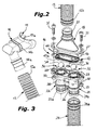
figure 2 is a perspective exploded view of a portion of the device offigure 1 , provided with a mouthpiece, -
figure 3 is a perspective exploded view of a portion of the device offigure 1 provided with a valve unit, with the relevant members, -
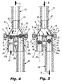
figures 4 and 5 are similar sectioned front elevational views of the portion of the device offigure 2 in the assembled condition, showing two opposite operational conditions of the device, and -
figure 6 is a schematic perspective view showing a support structure that can be worn by a user, to which a breathing device according to the invention is fixed. - With reference to the figures, an emergency breathing device according to the invention, indicated 10 in its whole, is intended to allow a user U to breathe below the snow mass of one avalanche, while waiting for the rescue.
- The
device 10 comprises a firstflexible pipe 12 to which an end 14a of amouthpiece holder 14 is connected at a first end thereof. Themouthpiece holder 14 has anotherend 14b to which aremovable mouthpiece 15 is connected, typically made of a plastic material such as silicone, that is intended to be inserted into the mouth of the user U and has a pair ofprojecting appendages 15a (only one of which can be seen infigure 2 ) to be engaged by the teeth of the user U, in order to facilitate holding thereof. - The
opposite end 12b of thefirst pipe 12 is connected to aunitary valve unit 16, the body of which includes a series of elements connected to each other and that, in particular, comprises a first and a second one-way or check valves, indicated 30 and 32 in the drawings, that will be described in detail in the following. - The body of the
unit 16 comprises a funnel-shaped member 18, typically of a plastic material such as polypropylene, having a first end from which atubular connector 20 extends to be connected to theend 12b of thepipe 12, and a second inside hollow end having a substantially elliptic profile. - The body of the
unit 16 comprises also adouble tube member 26, preferably made of the same material of themember 18, constituted by a pair of intake and exhausttubular ducts shaded connection end - Although both such connection ends 22a and 24a can be connected with respective pipes in order to divide the inspiration zone from the discharge zone in which they open, respectively, it is sufficient that only one of them be provided with a respective pipe with the aim of spacing such inspiration and discharge zones. For example, and according to the embodiment shown in the figures, only the
connection 24a of theduct 24 is connected to theend 28a of a respectiveflexible pipe 28, theopposite end 28b of which is spaced from theconnection end 24a. As an alternative, at least one portion of an auxiliary pipe (not shown), of a type analogou to thepipe 28, is connected to theconnection end 22a. - The one-
way valve 30, of the type provided with a freely slidable shutter, that preferably consists of aball 34, is associated to theduct 22. - In an analogous manner, a one-
way valve 32, also of the type provided with a freely slidable shutter, that preferably consists of aball 36 equal to theball 34, is associated to theduct 24. - An annular narrowing is provided inside the
duct 22, for example formed by moulding themember 26, in order to make avalve seat 38 for theball 34, while at least aprojection 40 radially extends from the inner surface of the wall of theduct 24, which constitutes an abutment member for theball 36. - A
plate member 42 is interposed between the funnel-shaped member 18 and thedouble tube member 26, also of a plastic material, the plan shape of which corresponds to the elliptic profile of themember 18 and to the profile of the end of theelement 26 opposite to theconnections circular openings 43a and 43b are formed in themember 42, which are intended to be arranged, in the assembled condition of the body of theunit 16, at positions respectively concentric with the axis of theducts radial projection 44 adapted to constitute an abutment member for theball 34 that is inserted with a clearance in theduct 22, while the opening 43a has a reduced diameter with respect to that of theduct 24, and constitutes avalve seat 46 for theball 36 that is inserted with a clearance in theduct 24. - Moreover, an
elliptic gasket 27 is interposed between the funnel-shaped member 18 and theplate member 42, while respectiveannular gaskets 29 are interposed between thedouble tube member 26 and each of theducts - The
members screws 31 andrespective nuts 33, which screws 31 engage coaxial holes formed at corresponding positions of thevarious members members - Preferably, the ball-
shaped shutters unit 16. In practice, the weight of theballs - Moreover, a tumbling and polishing surface treatment is conveniently carried out on the ball-
shaped shutters - Since in the two one-
way valves respective valve seats respective stop members valves - As a result of the fact that the ball-
shaped shutters respective ducts ball 34 is free to slide between itsvalve seat 38 and thestop member 44, while theball 36 is free to slide between itsvalve seat 46 and thestop member 40. When thedevice 10 is not used for breathing, theballs balls respective ducts valve unit 16 to be freely discharged from thedevice 10 and, on the other hand, locking of theballs - According to an alternative embodiment not shown in the figures, the
balls respective ducts 22ann 24, in order to hold such balls, in the rest condition of thevalves respective valve seats relevant abutment members - Moreover, the surface of the
valve seats balls balls seats valves balls 34 36 and therespective seats balls - The
flexible pipes device 10 are conveniently made of an elastomeric material so as to have "anti-throttling" characteristic, in order to avoid that their cross-section may be obstructed as a result of bending. For this purpose, thepipes - To connect in a reliable and safe manner the ends 12b and 28a of the
pipes duct 20 and with theconnection end 24a, theduct 20 and theend 24a are provided with a zone having a narrow cross-section to be engaged by a corresponding annular inner projection of theends pipes duct 20 and theconnection end 24a, in order to prevent any possibility of accidental removal of said pipes. These bands are conveniently covered by a sheath (also not shown) of thermo-shrinking plastic material. - The
device 10 is preferably associated with a support structure, such as a shoulder-belt harness 50 or any support member of a type known per se adapted to be worn by the user U, to enable it to be transported and to allow, if necessary, the user to put quickly to the mouth themouthpiece 15 connected to themouthpiece holder 14. In particular, thesupport structure 50 is provided with connection means 52 of a type known per se, generically shown as hangers infigure 6 , in order to allow thedevice 10 and its members to be fixed so as to be firmly withheld on thestructure 50. Such connection means 52 could be conveniently made by removable connection means of the Velcro® type. - Moreover, the
valve unit 16, thepipe 28 and a portion of thepipe 12 are preferably covered by a textile casing (not shown) fixed to thestructure 50, which constitutes a member of partial protection for thedevice 10. This textile casing can be so shaped as to form a storing pocket to allow themouthpiece holder 14 and therespective mouthpiece 15 to be housed when they are not used by the user U. - An anti-storm mask (not shown) is conveniently associated with the
mouthpiece holder 14 or to theend 12a of thepipe 12 for protecting the face of the user U, which is typically made of a textile or similar material, and is provided with connection means that consist of an opening or a holding member of a type known per se, adapted to be engaged by themouthpiece holder 14 or by theend 12a. The opposite ends of the mask are provided with mutual connection members, for example of the Velcro® type, in order to allow such a mask to be secured in an adjustable manner to the head of the user, behind his neck. This mask allows the user to hold themouthpiece 15 and therespective mouthpiece holder 14 in a more reliable manner, in the event of an avalanche. - In the use of the
device 10, when, for example, the user U believes that an avalanche risk may occur in proximity of his path, he put into his mouth themouthpiece 15 and press theappendages 15a between his teeth. In the case in which the protection mask is associated with themouthpiece holder 14 and/or with theend 12a of thepipe 12, the user U connects the opposite ends of the mask behind his neck, so as to obtain a still more reliable connecticn of themouthpiece 15. The user can therefore inhale air from themouthpiece 15 through thepipe 12 and theintake duct 22 of the unit 16 (according to arrows A offigures 4 and6 ) since, during the inhaling step, the one-way valve 30 is in its open condition in which itsspherical shutter 34, owing to low pressure caused by inhaling, contacts theabutment member 44 and is spaced from theseat 38. In this circumstance, thevalve 32 is in its closed condition, since its ball-shapedshutter 36, owing to low pressure caused by inhaling, engages therespective seat 46 and remains spaced from theabutment member 40. - In the subsequent exhaling step, the user U discharges air by the
mouthpiece 15 through thepipe 12, theexhaust duct 24 of theunit 16 and the pipe 28 (arrows B offigures 5 and6 ). In this case, the one-way valve 30 is in its closed condition, owing to pressure exerted as a result of exhaling, in which the ball-shapedshutter 34 engages theseat 38 and is spaced from theabutment member 44, while thevalve 32 is in its open condition, with its ball-shapedshutter 36 spaced from therespective seat 46 and resting on theabutment member 40, as a result of the pressure exerted by exhaling. - At the end of the use of the
device 10, the user removes themouthpiece 15 and, in the case in which the above mentioned storing pocket is associated with the possible textile casing of thedevice 10, he houses themouthpiece 15 and therespective mouthpiece holder 14 in this pocket till a new use.
Claims (17)
- Emergency breathing device, particularly to enable breathing below a snow mass, comprising a mouthpiece (14, 15) to be used by a user (U), which is connected to an air intake duct (22) for inhaling air from an inspiration zone, and to an exhaust duct (24, 28) for exhaling air to a discharge zone remote from the inspiration zone, which ducts are associated with a valve unit (16) comprising respective one-way valves (30, 32) to allow the user (U) to inhale air by the mouthpiece (14, 15) only through the intake duct (22), and to exhale air by the mouthpiece (14, 15) only through the exhaust duct (24, 28),
characterized in that said valve unit (16) comprises a unitary body (18, 26, 42) defining a first connection (20) to be operatively connected to the mouthpiece (14, 15), for the selective passage of the air incoming and outcoming with respect to the valve unit (16), respectively exhaled and inhaled by the user (U), a second connection (22a) associated with the intake duct (22), and a third connection (24a) associated with the exhaust duct (24, 28), wherein said one-way valves (30, 32) are of the slidable shutter type, are partially formed by said second and third connection (30, 32) of the body (16), and are directed to opposite directions, whereby when one of them is opened the other one (32, 30) is closed. - Device according to claim 1, characterized in that the shutters of the one-way valves (30, 32) of the valve unit (16) consist of balls (34, 36).
- Device according to claim 1 or 2, characterized in that said balls (34, 36) are made by a low density plastic material, such as polypropylene (PP) or polyoxymethylene (POM) .
- Device according to claim 3, characterized in that the weight of said balls (34, 36) is in the range between 0.5 and 1.5 g.
- Device according to claim 3 or 4, characterized in that a tumbling and polishing surface treatment is carried out on said balls (34, 36).
- Device according to any one of claims 1 to 5, characterized in that said body (16) defines respective valve seats (38, 44) for the shutters (34, 36) of the one-way valves (30, 32), as well as abutment members (40, 46), at the side opposite to said valve seats (38, 40), to stop sliding of said shutters (34, 36).
- Device according to claim 6, characterized in that the body (16) comprises a substantially funnel-shaped first member (18) to which said first connection (20) is associated.
- Device according to claim 6 or 7, characterized in that the body (16) comprises a second member (26) defining a pair of substantially parallel integral tubular members adapted to constitute said second and third connection (22a, 24a), the second connection (22a) having an inner valve seat (38) and the third connection (24) having at least an inner abutment member (40) adapted to stop sliding of the respective shutter (36).
- Device according to claims 7 or 8, characterized in that a third member (42) is interposed between the first and the second member (18, 26) of the body (16), said third member (42) being adapted to form at least an abutment member (44) to stop sliding of the shutter (34) of one one-way valve (30), and a valve seat (46) for the other one-way valve (32).
- Device according to any one of claims 6 to 9, characterized in that the valve seats (38, 46) of said one-way valves (30, 32) have a non flat, in particular toothed or corrugated, surface that faces the respective shutter 34, 36), so that the shutters (34, 36), in their condition in which they rest on the respective seats (38, 46), define a series of substantially punctiform contact zones.
- Device according to any one of claims 6 to 10, characterized in that said one-way valves (30, 32) comprise elastic return means, preferably consisting of springs, associated with the respective shutters (34, 36) in order to hold them, in the inactive condition of the valves (30, 32), in a substantially middle position between the respective valve seat (38, 46) and the respective abutment member (44, 40).
- Device according to any one of claims 1 to 11, characterized in that respective flexible service pipes (12, 28) extend between said first connection (20) and the mouthpiece (14, 15), as well as between the third connection (24a) and the zone in which exhaled air is discharged, which pipes have their inner wall substantially smooth and their outer wall corrugated.
- Device according to claim 12, characterized in that the corrugated outer wall of said pipes (12, 28) comprises a series of annular corrugations the cross-section of which, with respect to the axis of the pipes (12, 28), is substantially trapezoidal so that flexibility of the pipes (12, 28) is limited as a result of the mutual resting of the flanks of adjacent annular corrugations.
- Device according to claim 12 or 13, characterized in that said pipes (12, 28) are fixed to the respective connections (20, 24) of the valve unit (16) and of the mouthpiece (14, 15) by outer annular bands of a plastic material, to prevent accidental removal of said pipes (12, 28) from the respective connections (20, 24a).
- Device according to any one of claims 1 to 14, characterized in that it comprises an anti-storm mask of textile or similar material, close to the mouthpiece (14, 15), which can be secured to the head of the user (U) by adjustable connection means, and is provided with a formation adapted to be engaged by said mouthpiece (14, 15) or by a portion of the breathing device (10) close to it.
- Support structure adapted to be worn by a user, particularly of the harness type, characterized in that it is provided with connection means to withhold an emergency breathing device (10) according to any one of claims 1 to 15.
- Structure according to claim 16, characterized in that it comprises a casing of textile or similar material, adapted to cover the valve unit (16) and at least one portion of said flexible pipes (12, 28), said casing preferably including a storing pocket for housing the mouthpiece (14, 15).
Applications Claiming Priority (1)
| Application Number | Priority Date | Filing Date | Title |
|---|---|---|---|
| IT000062A ITTO20120062A1 (en) | 2012-01-25 | 2012-01-25 | EMERGENCY RESPIRATOR DEVICE TO PERMIT TO BREATHE UNDERNEATH A SNOW MASS. |
Publications (2)
| Publication Number | Publication Date |
|---|---|
| EP2620181A1 true EP2620181A1 (en) | 2013-07-31 |
| EP2620181B1 EP2620181B1 (en) | 2019-12-25 |
Family
ID=46001420
Family Applications (1)
| Application Number | Title | Priority Date | Filing Date |
|---|---|---|---|
| EP13000315.5A Active EP2620181B1 (en) | 2012-01-25 | 2013-01-22 | Emergency breathing device adapted to enable breathing below a mass of snow |
Country Status (2)
| Country | Link |
|---|---|
| EP (1) | EP2620181B1 (en) |
| IT (1) | ITTO20120062A1 (en) |
Cited By (8)
| Publication number | Priority date | Publication date | Assignee | Title |
|---|---|---|---|---|
| EP3042586A1 (en) | 2015-01-08 | 2016-07-13 | Ferrino & C. S.p.A. | Backpack with safety system to be activated in the case of an avalanche |
| WO2017077074A1 (en) | 2015-11-05 | 2017-05-11 | Mamaloha Gmbh | Avalanche protection device |
| DE102017103216A1 (en) | 2017-02-16 | 2018-08-16 | Hochschule Furtwangen | Avalanche breathing apparatus for supplying an avalanche victim with breathing air |
| WO2018220590A1 (en) * | 2017-06-02 | 2018-12-06 | Julian Stuart | Breathing device |
| US11331521B2 (en) | 2016-10-26 | 2022-05-17 | ADVENATE GmbH | Breathing aid |
| RU230239U1 (en) * | 2024-07-18 | 2024-11-22 | Дмитрий Олегович Ахмеров | AVALANCHE SELF-RESCUER |
| EP4429780A4 (en) * | 2021-11-12 | 2025-10-08 | Safeback As | SURVIVAL DEVICE FOR THE EVEN SUPPLY OF BREATHING AIR INTO AN ENVIRONMENT |
| WO2026019339A1 (en) * | 2024-07-18 | 2026-01-22 | Дмитрий Олегович АХМЕРОВ | Avalanche self-rescue breathing apparatus |
Citations (5)
| Publication number | Priority date | Publication date | Assignee | Title |
|---|---|---|---|---|
| FR2915E (en) | 1896-06-25 | 1904-07-25 | Eugene Joseph Mahot | Improvement brought to sprayers by an arrangement of movements |
| US4683869A (en) * | 1986-05-06 | 1987-08-04 | Wilcox Robert B | Breath transfer device |
| US5490501A (en) | 1994-05-16 | 1996-02-13 | Crowley; Thomas J. | Avalanche victim's air-from-snow breathing device |
| EP0998959A1 (en) * | 1998-11-06 | 2000-05-10 | Black Diamond Equipment, Ltd. | Emergency breathing device |
| US20060212103A1 (en) * | 2005-03-21 | 2006-09-21 | Wagner Iii Fred A | Circulation Apparatus and Method for Use of Same |
-
2012
- 2012-01-25 IT IT000062A patent/ITTO20120062A1/en unknown
-
2013
- 2013-01-22 EP EP13000315.5A patent/EP2620181B1/en active Active
Patent Citations (5)
| Publication number | Priority date | Publication date | Assignee | Title |
|---|---|---|---|---|
| FR2915E (en) | 1896-06-25 | 1904-07-25 | Eugene Joseph Mahot | Improvement brought to sprayers by an arrangement of movements |
| US4683869A (en) * | 1986-05-06 | 1987-08-04 | Wilcox Robert B | Breath transfer device |
| US5490501A (en) | 1994-05-16 | 1996-02-13 | Crowley; Thomas J. | Avalanche victim's air-from-snow breathing device |
| EP0998959A1 (en) * | 1998-11-06 | 2000-05-10 | Black Diamond Equipment, Ltd. | Emergency breathing device |
| US20060212103A1 (en) * | 2005-03-21 | 2006-09-21 | Wagner Iii Fred A | Circulation Apparatus and Method for Use of Same |
Cited By (9)
| Publication number | Priority date | Publication date | Assignee | Title |
|---|---|---|---|---|
| EP3042586A1 (en) | 2015-01-08 | 2016-07-13 | Ferrino & C. S.p.A. | Backpack with safety system to be activated in the case of an avalanche |
| WO2017077074A1 (en) | 2015-11-05 | 2017-05-11 | Mamaloha Gmbh | Avalanche protection device |
| US11331521B2 (en) | 2016-10-26 | 2022-05-17 | ADVENATE GmbH | Breathing aid |
| DE102017103216A1 (en) | 2017-02-16 | 2018-08-16 | Hochschule Furtwangen | Avalanche breathing apparatus for supplying an avalanche victim with breathing air |
| DE102017103216B4 (en) | 2017-02-16 | 2020-07-09 | Hochschule Furtwangen | Avalanche breathing apparatus to supply an avalanche victim with breathing air |
| WO2018220590A1 (en) * | 2017-06-02 | 2018-12-06 | Julian Stuart | Breathing device |
| EP4429780A4 (en) * | 2021-11-12 | 2025-10-08 | Safeback As | SURVIVAL DEVICE FOR THE EVEN SUPPLY OF BREATHING AIR INTO AN ENVIRONMENT |
| RU230239U1 (en) * | 2024-07-18 | 2024-11-22 | Дмитрий Олегович Ахмеров | AVALANCHE SELF-RESCUER |
| WO2026019339A1 (en) * | 2024-07-18 | 2026-01-22 | Дмитрий Олегович АХМЕРОВ | Avalanche self-rescue breathing apparatus |
Also Published As
| Publication number | Publication date |
|---|---|
| EP2620181B1 (en) | 2019-12-25 |
| ITTO20120062A1 (en) | 2013-07-26 |
Similar Documents
| Publication | Publication Date | Title |
|---|---|---|
| EP2620181B1 (en) | Emergency breathing device adapted to enable breathing below a mass of snow | |
| US8590533B2 (en) | Adjustable inhalation resistence exercise device | |
| AU2014212711B2 (en) | Respiratory mask having a clean air inlet chamber | |
| US8534283B2 (en) | Peep valve with filter | |
| US9993668B2 (en) | Face mask assembly | |
| US20160129287A1 (en) | Scent Suppression Mask | |
| US20070175478A1 (en) | Nasal air purifier | |
| US20130186393A1 (en) | Valved holding chamber including valve retention system | |
| CN106456919A (en) | Respiratory device with unidirectional valve for attaching active venting system | |
| CA2808043A1 (en) | Respiratory therapy device having standard and oscillatory pep with nebulizer | |
| CN109069887A (en) | Multicell respirator sealing device and method | |
| JP2009511146A (en) | Respiratory protection | |
| US20240024707A1 (en) | Generic modular respirator | |
| US20170112605A1 (en) | Portable artificial respirator for pet | |
| US20070095348A1 (en) | Particulate blocking oxygen delivery mask | |
| KR101294333B1 (en) | Rescue breathing device | |
| KR20200020088A (en) | Fine dusk blocking respirator | |
| KR20200028646A (en) | Mask for nostrils | |
| US20150283410A1 (en) | Respirator mask | |
| US6807964B1 (en) | Cold weather breathing device | |
| US20170291045A1 (en) | Discharger structure on earloop face masks | |
| US9403043B2 (en) | Air warming apparatus | |
| EP0998959A1 (en) | Emergency breathing device | |
| CN102639193B (en) | breathing apparatus with filter | |
| US20140345627A1 (en) | Helmet moisture control system |
Legal Events
| Date | Code | Title | Description |
|---|---|---|---|
| PUAI | Public reference made under article 153(3) epc to a published international application that has entered the european phase |
Free format text: ORIGINAL CODE: 0009012 |
|
| AK | Designated contracting states |
Kind code of ref document: A1 Designated state(s): AL AT BE BG CH CY CZ DE DK EE ES FI FR GB GR HR HU IE IS IT LI LT LU LV MC MK MT NL NO PL PT RO RS SE SI SK SM TR |
|
| RBV | Designated contracting states (corrected) |
Designated state(s): AL AT BE BG CH CY CZ DE DK EE ES FI FR GB GR HR HU IE IS IT LI LT LU LV MC MK MT NL NO PL PT RO RS SE SI SK SM TR |
|
| 17P | Request for examination filed |
Effective date: 20140129 |
|
| STAA | Information on the status of an ep patent application or granted ep patent |
Free format text: STATUS: EXAMINATION IS IN PROGRESS |
|
| 17Q | First examination report despatched |
Effective date: 20180425 |
|
| GRAP | Despatch of communication of intention to grant a patent |
Free format text: ORIGINAL CODE: EPIDOSNIGR1 |
|
| STAA | Information on the status of an ep patent application or granted ep patent |
Free format text: STATUS: GRANT OF PATENT IS INTENDED |
|
| INTG | Intention to grant announced |
Effective date: 20190524 |
|
| GRAS | Grant fee paid |
Free format text: ORIGINAL CODE: EPIDOSNIGR3 |
|
| GRAA | (expected) grant |
Free format text: ORIGINAL CODE: 0009210 |
|
| STAA | Information on the status of an ep patent application or granted ep patent |
Free format text: STATUS: THE PATENT HAS BEEN GRANTED |
|
| AK | Designated contracting states |
Kind code of ref document: B1 Designated state(s): AL AT BE BG CH CY CZ DE DK EE ES FI FR GB GR HR HU IE IS IT LI LT LU LV MC MK MT NL NO PL PT RO RS SE SI SK SM TR |
|
| REG | Reference to a national code |
Ref country code: GB Ref legal event code: FG4D |
|
| REG | Reference to a national code |
Ref country code: CH Ref legal event code: EP Ref country code: AT Ref legal event code: REF Ref document number: 1185552 Country of ref document: AT Kind code of ref document: T Effective date: 20191015 |
|
| REG | Reference to a national code |
Ref country code: DE Ref legal event code: R096 Ref document number: 602013061144 Country of ref document: DE |
|
| REG | Reference to a national code |
Ref country code: IE Ref legal event code: FG4D |
|
| PUAC | Information related to the publication of a b1 document modified or deleted |
Free format text: ORIGINAL CODE: 0009299EPPU |
|
| STAA | Information on the status of an ep patent application or granted ep patent |
Free format text: STATUS: GRANT OF PATENT IS INTENDED |
|
| REG | Reference to a national code |
Ref country code: CH Ref legal event code: PK Free format text: DIE ERTEILUNG WURDE VOM EPA WIDERRUFEN. |
|
| GRAA | (expected) grant |
Free format text: ORIGINAL CODE: 0009210 |
|
| STAA | Information on the status of an ep patent application or granted ep patent |
Free format text: STATUS: THE PATENT HAS BEEN GRANTED |
|
| DB1 | Publication of patent cancelled |
Effective date: 20191108 |
|
| REG | Reference to a national code |
Ref country code: DE Ref legal event code: R107 Ref document number: 602013061144 Country of ref document: DE |
|
| AK | Designated contracting states |
Kind code of ref document: B1 Designated state(s): AL AT BE BG CH CY CZ DE DK EE ES FI FR GB GR HR HU IE IS IT LI LT LU LV MC MK MT NL NO PL PT RO RS SE SI SK SM TR |
|
| REG | Reference to a national code |
Ref country code: CH Ref legal event code: EP |
|
| REG | Reference to a national code |
Ref country code: LU Ref legal event code: HK Effective date: 20191204 |
|
| REG | Reference to a national code |
Ref country code: CH Ref legal event code: PK Free format text: DIE ERTEILUNG VOM 02.10.2019 WURDE VOM EPA WIDERRUFEN. Ref country code: AT Ref legal event code: REF Ref document number: 1185552 Country of ref document: AT Kind code of ref document: T Effective date: 20200115 |
|
| REG | Reference to a national code |
Ref country code: DE Ref legal event code: R096 Ref document number: 602013061144 Country of ref document: DE |
|
| REG | Reference to a national code |
Ref country code: NL Ref legal event code: MP Effective date: 20191225 |
|
| PG25 | Lapsed in a contracting state [announced via postgrant information from national office to epo] |
Ref country code: BG Free format text: LAPSE BECAUSE OF FAILURE TO SUBMIT A TRANSLATION OF THE DESCRIPTION OR TO PAY THE FEE WITHIN THE PRESCRIBED TIME-LIMIT Effective date: 20200325 Ref country code: GR Free format text: LAPSE BECAUSE OF FAILURE TO SUBMIT A TRANSLATION OF THE DESCRIPTION OR TO PAY THE FEE WITHIN THE PRESCRIBED TIME-LIMIT Effective date: 20200103 Ref country code: FI Free format text: LAPSE BECAUSE OF FAILURE TO SUBMIT A TRANSLATION OF THE DESCRIPTION OR TO PAY THE FEE WITHIN THE PRESCRIBED TIME-LIMIT Effective date: 20191225 Ref country code: NO Free format text: LAPSE BECAUSE OF FAILURE TO SUBMIT A TRANSLATION OF THE DESCRIPTION OR TO PAY THE FEE WITHIN THE PRESCRIBED TIME-LIMIT Effective date: 20200102 Ref country code: LT Free format text: LAPSE BECAUSE OF FAILURE TO SUBMIT A TRANSLATION OF THE DESCRIPTION OR TO PAY THE FEE WITHIN THE PRESCRIBED TIME-LIMIT Effective date: 20191225 |
|
| REG | Reference to a national code |
Ref country code: LT Ref legal event code: MG4D |
|
| PG25 | Lapsed in a contracting state [announced via postgrant information from national office to epo] |
Ref country code: HR Free format text: LAPSE BECAUSE OF FAILURE TO SUBMIT A TRANSLATION OF THE DESCRIPTION OR TO PAY THE FEE WITHIN THE PRESCRIBED TIME-LIMIT Effective date: 20191225 Ref country code: IS Free format text: LAPSE BECAUSE OF FAILURE TO SUBMIT A TRANSLATION OF THE DESCRIPTION OR TO PAY THE FEE WITHIN THE PRESCRIBED TIME-LIMIT Effective date: 20200224 Ref country code: RS Free format text: LAPSE BECAUSE OF FAILURE TO SUBMIT A TRANSLATION OF THE DESCRIPTION OR TO PAY THE FEE WITHIN THE PRESCRIBED TIME-LIMIT Effective date: 20191225 |
|
| PG25 | Lapsed in a contracting state [announced via postgrant information from national office to epo] |
Ref country code: AL Free format text: LAPSE BECAUSE OF FAILURE TO SUBMIT A TRANSLATION OF THE DESCRIPTION OR TO PAY THE FEE WITHIN THE PRESCRIBED TIME-LIMIT Effective date: 20191225 |
|
| PG2D | Information on lapse in contracting state deleted |
Ref country code: IS |
|
| PG25 | Lapsed in a contracting state [announced via postgrant information from national office to epo] |
Ref country code: PT Free format text: LAPSE BECAUSE OF FAILURE TO SUBMIT A TRANSLATION OF THE DESCRIPTION OR TO PAY THE FEE WITHIN THE PRESCRIBED TIME-LIMIT Effective date: 20200520 Ref country code: NL Free format text: LAPSE BECAUSE OF FAILURE TO SUBMIT A TRANSLATION OF THE DESCRIPTION OR TO PAY THE FEE WITHIN THE PRESCRIBED TIME-LIMIT Effective date: 20191225 Ref country code: EE Free format text: LAPSE BECAUSE OF FAILURE TO SUBMIT A TRANSLATION OF THE DESCRIPTION OR TO PAY THE FEE WITHIN THE PRESCRIBED TIME-LIMIT Effective date: 20191225 Ref country code: RO Free format text: LAPSE BECAUSE OF FAILURE TO SUBMIT A TRANSLATION OF THE DESCRIPTION OR TO PAY THE FEE WITHIN THE PRESCRIBED TIME-LIMIT Effective date: 20191225 Ref country code: IS Free format text: LAPSE BECAUSE OF FAILURE TO SUBMIT A TRANSLATION OF THE DESCRIPTION OR TO PAY THE FEE WITHIN THE PRESCRIBED TIME-LIMIT Effective date: 20200202 |
|
| PG25 | Lapsed in a contracting state [announced via postgrant information from national office to epo] |
Ref country code: SM Free format text: LAPSE BECAUSE OF FAILURE TO SUBMIT A TRANSLATION OF THE DESCRIPTION OR TO PAY THE FEE WITHIN THE PRESCRIBED TIME-LIMIT Effective date: 20191225 Ref country code: SK Free format text: LAPSE BECAUSE OF FAILURE TO SUBMIT A TRANSLATION OF THE DESCRIPTION OR TO PAY THE FEE WITHIN THE PRESCRIBED TIME-LIMIT Effective date: 20191225 |
|
| REG | Reference to a national code |
Ref country code: AT Ref legal event code: MM01 Ref document number: 1185552 Country of ref document: AT Kind code of ref document: T Effective date: 20200122 |
|
| REG | Reference to a national code |
Ref country code: DE Ref legal event code: R097 Ref document number: 602013061144 Country of ref document: DE |
|
| PG25 | Lapsed in a contracting state [announced via postgrant information from national office to epo] |
Ref country code: MC Free format text: LAPSE BECAUSE OF FAILURE TO SUBMIT A TRANSLATION OF THE DESCRIPTION OR TO PAY THE FEE WITHIN THE PRESCRIBED TIME-LIMIT Effective date: 20191225 |
|
| REG | Reference to a national code |
Ref country code: BE Ref legal event code: MM Effective date: 20200131 |
|
| PG25 | Lapsed in a contracting state [announced via postgrant information from national office to epo] |
Ref country code: LU Free format text: LAPSE BECAUSE OF NON-PAYMENT OF DUE FEES Effective date: 20200122 Ref country code: DK Free format text: LAPSE BECAUSE OF FAILURE TO SUBMIT A TRANSLATION OF THE DESCRIPTION OR TO PAY THE FEE WITHIN THE PRESCRIBED TIME-LIMIT Effective date: 20191225 Ref country code: CZ Free format text: LAPSE BECAUSE OF FAILURE TO SUBMIT A TRANSLATION OF THE DESCRIPTION OR TO PAY THE FEE WITHIN THE PRESCRIBED TIME-LIMIT Effective date: 20191225 Ref country code: ES Free format text: LAPSE BECAUSE OF FAILURE TO SUBMIT A TRANSLATION OF THE DESCRIPTION OR TO PAY THE FEE WITHIN THE PRESCRIBED TIME-LIMIT Effective date: 20191225 |
|
| PLBE | No opposition filed within time limit |
Free format text: ORIGINAL CODE: 0009261 |
|
| STAA | Information on the status of an ep patent application or granted ep patent |
Free format text: STATUS: NO OPPOSITION FILED WITHIN TIME LIMIT |
|
| PG25 | Lapsed in a contracting state [announced via postgrant information from national office to epo] |
Ref country code: AT Free format text: LAPSE BECAUSE OF NON-PAYMENT OF DUE FEES Effective date: 20200122 Ref country code: SI Free format text: LAPSE BECAUSE OF FAILURE TO SUBMIT A TRANSLATION OF THE DESCRIPTION OR TO PAY THE FEE WITHIN THE PRESCRIBED TIME-LIMIT Effective date: 20191225 Ref country code: BE Free format text: LAPSE BECAUSE OF NON-PAYMENT OF DUE FEES Effective date: 20200131 |
|
| 26N | No opposition filed |
Effective date: 20200928 |
|
| PG25 | Lapsed in a contracting state [announced via postgrant information from national office to epo] |
Ref country code: IE Free format text: LAPSE BECAUSE OF NON-PAYMENT OF DUE FEES Effective date: 20200122 |
|
| REG | Reference to a national code |
Ref country code: DE Ref legal event code: R082 Ref document number: 602013061144 Country of ref document: DE Representative=s name: KUHNEN & WACKER PATENT- UND RECHTSANWALTSBUERO, DE |
|
| PG25 | Lapsed in a contracting state [announced via postgrant information from national office to epo] |
Ref country code: TR Free format text: LAPSE BECAUSE OF FAILURE TO SUBMIT A TRANSLATION OF THE DESCRIPTION OR TO PAY THE FEE WITHIN THE PRESCRIBED TIME-LIMIT Effective date: 20191225 Ref country code: MT Free format text: LAPSE BECAUSE OF FAILURE TO SUBMIT A TRANSLATION OF THE DESCRIPTION OR TO PAY THE FEE WITHIN THE PRESCRIBED TIME-LIMIT Effective date: 20191225 Ref country code: CY Free format text: LAPSE BECAUSE OF FAILURE TO SUBMIT A TRANSLATION OF THE DESCRIPTION OR TO PAY THE FEE WITHIN THE PRESCRIBED TIME-LIMIT Effective date: 20191225 |
|
| PG25 | Lapsed in a contracting state [announced via postgrant information from national office to epo] |
Ref country code: SE Free format text: LAPSE BECAUSE OF FAILURE TO SUBMIT A TRANSLATION OF THE DESCRIPTION OR TO PAY THE FEE WITHIN THE PRESCRIBED TIME-LIMIT Effective date: 20191225 Ref country code: NO Free format text: LAPSE BECAUSE OF FAILURE TO SUBMIT A TRANSLATION OF THE DESCRIPTION OR TO PAY THE FEE WITHIN THE PRESCRIBED TIME-LIMIT Effective date: 20200102 Ref country code: MK Free format text: LAPSE BECAUSE OF FAILURE TO SUBMIT A TRANSLATION OF THE DESCRIPTION OR TO PAY THE FEE WITHIN THE PRESCRIBED TIME-LIMIT Effective date: 20191225 |
|
| PG25 | Lapsed in a contracting state [announced via postgrant information from national office to epo] |
Ref country code: LV Free format text: LAPSE BECAUSE OF FAILURE TO SUBMIT A TRANSLATION OF THE DESCRIPTION OR TO PAY THE FEE WITHIN THE PRESCRIBED TIME-LIMIT Effective date: 20191225 |
|
| P01 | Opt-out of the competence of the unified patent court (upc) registered |
Effective date: 20230603 |
|
| PG25 | Lapsed in a contracting state [announced via postgrant information from national office to epo] |
Ref country code: PL Free format text: LAPSE BECAUSE OF FAILURE TO SUBMIT A TRANSLATION OF THE DESCRIPTION OR TO PAY THE FEE WITHIN THE PRESCRIBED TIME-LIMIT Effective date: 20191225 |
|
| PGFP | Annual fee paid to national office [announced via postgrant information from national office to epo] |
Ref country code: DE Payment date: 20240123 Year of fee payment: 12 Ref country code: GB Payment date: 20240123 Year of fee payment: 12 |
|
| REG | Reference to a national code |
Ref country code: DE Ref legal event code: R119 Ref document number: 602013061144 Country of ref document: DE |
|
| GBPC | Gb: european patent ceased through non-payment of renewal fee |
Effective date: 20250122 |
|
| PG25 | Lapsed in a contracting state [announced via postgrant information from national office to epo] |
Ref country code: DE Free format text: LAPSE BECAUSE OF NON-PAYMENT OF DUE FEES Effective date: 20250801 |
|
| PG25 | Lapsed in a contracting state [announced via postgrant information from national office to epo] |
Ref country code: GB Free format text: LAPSE BECAUSE OF NON-PAYMENT OF DUE FEES Effective date: 20250122 |
|
| REG | Reference to a national code |
Ref country code: CH Ref legal event code: U11 Free format text: ST27 STATUS EVENT CODE: U-0-0-U10-U11 (AS PROVIDED BY THE NATIONAL OFFICE) Effective date: 20260201 |
|
| PGFP | Annual fee paid to national office [announced via postgrant information from national office to epo] |
Ref country code: IT Payment date: 20260127 Year of fee payment: 14 |
|
| PGFP | Annual fee paid to national office [announced via postgrant information from national office to epo] |
Ref country code: FR Payment date: 20260130 Year of fee payment: 14 |
|
| PGFP | Annual fee paid to national office [announced via postgrant information from national office to epo] |
Ref country code: CH Payment date: 20260201 Year of fee payment: 14 |