EP2629099B1 - Système de transport pour échantillons de matériau, notamment échantillons médicaux - Google Patents
Système de transport pour échantillons de matériau, notamment échantillons médicaux Download PDFInfo
- Publication number
- EP2629099B1 EP2629099B1 EP12155634.4A EP12155634A EP2629099B1 EP 2629099 B1 EP2629099 B1 EP 2629099B1 EP 12155634 A EP12155634 A EP 12155634A EP 2629099 B1 EP2629099 B1 EP 2629099B1
- Authority
- EP
- European Patent Office
- Prior art keywords
- sample holder
- wheel
- conveying system
- conveyor
- sample
- Prior art date
- Legal status (The legal status is an assumption and is not a legal conclusion. Google has not performed a legal analysis and makes no representation as to the accuracy of the status listed.)
- Active
Links
Images

Classifications
-
- G—PHYSICS
- G01—MEASURING; TESTING
- G01N—INVESTIGATING OR ANALYSING MATERIALS BY DETERMINING THEIR CHEMICAL OR PHYSICAL PROPERTIES
- G01N35/00—Automatic analysis not limited to methods or materials provided for in any single one of groups G01N1/00 - G01N33/00; Handling materials therefor
- G01N35/02—Automatic analysis not limited to methods or materials provided for in any single one of groups G01N1/00 - G01N33/00; Handling materials therefor using a plurality of sample containers moved by a conveyor system past one or more treatment or analysis stations
- G01N35/04—Details of the conveyor system
- G01N2035/0401—Sample carriers, cuvettes or reaction vessels
- G01N2035/0406—Individual bottles or tubes
-
- G—PHYSICS
- G01—MEASURING; TESTING
- G01N—INVESTIGATING OR ANALYSING MATERIALS BY DETERMINING THEIR CHEMICAL OR PHYSICAL PROPERTIES
- G01N35/00—Automatic analysis not limited to methods or materials provided for in any single one of groups G01N1/00 - G01N33/00; Handling materials therefor
- G01N35/02—Automatic analysis not limited to methods or materials provided for in any single one of groups G01N1/00 - G01N33/00; Handling materials therefor using a plurality of sample containers moved by a conveyor system past one or more treatment or analysis stations
- G01N35/04—Details of the conveyor system
- G01N2035/046—General conveyor features
- G01N2035/0467—Switching points ("aiguillages")
-
- G—PHYSICS
- G01—MEASURING; TESTING
- G01N—INVESTIGATING OR ANALYSING MATERIALS BY DETERMINING THEIR CHEMICAL OR PHYSICAL PROPERTIES
- G01N35/00—Automatic analysis not limited to methods or materials provided for in any single one of groups G01N1/00 - G01N33/00; Handling materials therefor
- G01N35/02—Automatic analysis not limited to methods or materials provided for in any single one of groups G01N1/00 - G01N33/00; Handling materials therefor using a plurality of sample containers moved by a conveyor system past one or more treatment or analysis stations
- G01N35/04—Details of the conveyor system
- G01N2035/0474—Details of actuating means for conveyors or pipettes
- G01N2035/0475—Details of actuating means for conveyors or pipettes electric, e.g. stepper motor, solenoid
-
- G—PHYSICS
- G01—MEASURING; TESTING
- G01N—INVESTIGATING OR ANALYSING MATERIALS BY DETERMINING THEIR CHEMICAL OR PHYSICAL PROPERTIES
- G01N35/00—Automatic analysis not limited to methods or materials provided for in any single one of groups G01N1/00 - G01N33/00; Handling materials therefor
- G01N35/02—Automatic analysis not limited to methods or materials provided for in any single one of groups G01N1/00 - G01N33/00; Handling materials therefor using a plurality of sample containers moved by a conveyor system past one or more treatment or analysis stations
- G01N35/04—Details of the conveyor system
- G01N2035/0474—Details of actuating means for conveyors or pipettes
- G01N2035/0489—Self-propelled units
Definitions
- the invention relates to a conveyor system for material samples, in particular medical samples according to the preamble of claim 1.
- Conceivable analyzes in different analyzers can, for example, in a blood sample, the investigation of the hemoglobin (HB value), a cholesterol content, content of uric acid or other medically relevant parameters.
- urine samples can be tested for their pH, red blood cell content, or overall protein content.
- FIG US 2005/0271555 A1 Another example of a conveyor system with self-propelled sample holders in a conveyor track along a conveyor line is shown in FIG US 2005/0271555 A1 disclosed.
- sample holders shown with at least two wheels, which sit on a rigid, driven axle, can move.
- the sample holders shown are provided with a circular base and move in U-shaped, tunnel-like, open-topped tracks, the side walls at the same time give a guide for the sample holder.
- the in the US 2005/0271555 A1 disclosed sample holders are each designed to receive a single, tubular sample vessel.
- the sample holder according to this document is equipped without a steerable axle, but a change in direction is achieved by a steering through the side walls of the web in the manner of a gang.
- curved or switch areas of the sample holder moves with a circular average against a wall of the guideway or in the course of the track swung Weichenstellwand and drives in this area as long against the wall or the Weichenstellwand until successively the rigid drive axis perpendicular to the new direction has aligned and the sample holder can pick up speed again.
- WO2011 / 118190 describes a positioning device in which a sample is mounted on a plate which can be brought limited by guide elements in different positions.
- the conveyor system for material samples has a conveyor track which forms at least one conveyor line. Furthermore, the system contains at least one self-propelled sample holder that can be moved along the conveyor line and that is designed to receive a sample container.
- This sample holder has a drive motor, an energy store for supplying the drive motor with drive energy and a frictional wheel drivable by the drive motor for transmitting a drive force on the conveyor track.
- the conveyor track has at least one guide structure for the formation of the conveyor track.
- the sample holder has on the underside at least two sliding elements, which lie in operation on the conveyor track and slide along the surface thereof.
- the wheel and the at least two sliding elements lie on the end points of a triangle and thus give the sample holder safe stability, so that it can move without overturning along the conveying path on the conveyor track.
- the guide along the conveying path is accomplished by means of a arranged on the underside of the sample holder guide element, which cooperates with the guide structure in the conveyor track.
- This combination of guide element and guide structure causes the directional specification for the self-propelled sample holder with respect to the direction along which it follows the conveyor line. In other words, the sample holder is guided by this interaction of the guide structure and guide element passively on the conveyor track.
- At least two sliding elements are arranged on its underside, which form further supporting points in addition to the support point of the friction wheel.
- the stability is achieved by the triangular arrangement between the at least two sliding elements and the wheel.
- the sliding elements should be selected so that they cause a low friction.
- appropriate materials are to be selected, in particular those with respect to the material of the conveyor track low sliding friction, for example, such a plastic.
- plastics such as Teflon or comparable low-friction plastics into consideration.
- the size of the sliding elements is to be kept correspondingly low, these may be formed, for example, as a sphere sections, resulting in almost punctiform supports on the conveyor track.
- the wheel has a rigid and non-steerable axle.
- a rigid and non-steerable axle is much simpler and more robust in terms of its structure and mechanics, resulting in a simpler construction, less expensive to produce and also more durable and robust sample holders.
- the wheel is arranged with its longitudinal extent along a central axis of the sample holder.
- the axis of rotation of the wheel then runs substantially perpendicular to the central axis.
- the self-propelled sample holder in a conveyor system behaves particularly favorably when the wheel is located on a first side of this projection starting from a position of the center of gravity of the sample holder and the guide element lies on a second, opposite side of the projection.
- Such an arrangement results in a particularly stable driving behavior and leadership behavior of the self-propelled sample holder along the conveyor line in curves and branches.
- a preferred embodiment of the guide structure and guide element is that the guide structure is a transversely to the surfaces of the guideway in the depth of which extending guide groove and that the guide element is arranged by a arranged on the underside of the sample holder, projecting from this guide pin.
- the guide pin is guided laterally in the guide groove and can slide along this groove along the longitudinal direction.
- the course of the guide groove specifies the direction for the movement of the sample holder.
- the guide pin has a circular cross section so that it can easily understand the rotational movements of the sample holder relative to the guide groove in cornering or branching. It is preferred that when inserted into the conveyor track sample holder of the guide pin does not reach into the groove bottom of the guide groove, so as not to generate additional friction. However, it may also be intended to rest the guide pin on the groove base, if this also represents one of the sliding elements. However, then it must be ensured that a correspondingly low friction is formed between the groove bottom and the distal tip of the guide pin.
- the sample holder can take any shape which is suitable for the purposes of the respective conveyor system in the specific embodiment.
- the sample holder has a substantially rectangular base area.
- Such has proven to be particularly easy to implement in the production and implementation and at the same time as practical in terms of the possible arrangement of the essential elements wheel, sliding elements and guide element on the underside of the sample holder.
- the rectangular base of the sample holder has beveled on the front side seen in the forward direction of travel corners. These chamfers serve in particular the arrangement of laterally acting sensors with which lateral areas can be monitored during forward travel for collision avoidance.
- the conveyor system according to the invention contains in particular such a sample holder, which is designed to receive a single, in particular tube-shaped, sample vessel and has a corresponding receptacle.
- the conveyor system according to the invention may consist of a conveyor track and only a single self-propelled sample holder. In practice, however, a large number of such sample holders will be used in the conveyor track to transfer large quantities of samples in the conveyor system to the respective destination and to enable automated processing.
- Fig. 1 a possible design variant of a conveyor system 1 is shown in a schematic perspective view.
- the conveyor system 1 contains a Conveyor track 2.
- guide grooves 3 are embedded in the depth of the conveyor track 2 and transversely to the surface thereof, the guide grooves 3 defining conveyor paths with their progressions.
- the guide grooves 3 at branches 4, where switches are arranged, branched and interconnected in various configurations, so that depending on the interconnection of the switches different conveyor lines can be formed or switched by interconnection of different courses of the guide grooves 3.
- a total of three self-propelled sample holder 5 are arranged in different sections. These can move self-propelled along the conveyor track in the manner described in more detail below.
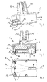
- a sample holder 5 is in the FIGS. 2 to 4 once again closer and presented in its details.
- the sample holder 5 has a base body 6 with a substantially rectangular base (see. Fig. 4 ).
- a housing formed by the base body 6 is broken by a friction wheel 8.
- the friction wheel 8 is (see. Fig. 4 ) is arranged in its longitudinal extension along a central axis 9 of the sample holder 5. It is based on a projection of a center of gravity of the sample holder 5 on a in Fig. 4 shown on the first page.
- the friction wheel 8 is a vertically extending from the bottom 7 downwardly extending guide pin 10, which is also located on the central axis 9 and so far aligned with the longitudinal extent of the friction wheel 8.
- the guide pin 10 is located on one of the position of the friction wheel 8 diametrically opposite side of the projection of the center of gravity, which is located between these two elements (in Fig. 4 not shown).
- two sliding elements 12 are arranged along a line 11 extending substantially perpendicular to the central axis 9, which project from the underside 7.
- These sliding elements 12 are made of a material which has a low sliding friction with respect to the material of the surface of the guide track 2, for example of a corresponding plastic such as Teflon.
- a receptacle for a single sample vessel in particular a tube-shaped sample vessel formed by holding fingers 13. Between the holding fingers 13, a tube-shaped sample vessel can be introduced up to the bottom of a dish-shaped receptacle 14.
- an accumulator 15 is disposed inside the base 6 of the sample holder 5. This feeds the drive motor (in Fig. 3 not shown), by means of which the friction wheel 8 can be brought into rotation, for the drive of the sample holder 5 with energy and also supplies other electrical consumers, which are arranged on the sample holder 5, such as distance sensors 17, which serve a collision warning monitoring.
- the friction wheel 8 is provided along its circumference with a friction lining 18, which serves to transmit power of the driving force to the surface of the conveyor track 2, so as to provide for the propulsion of the sample holder 5.
- the friction wheel 8 rotates about an axis 16, which is a rigid and non-steerable axis.
- Fig. 5 Finally, it can be seen how the sample holder 5 is seated on the conveyor track 2 during operation, wherein the guide pin 10 protrudes into the guide groove 3 and gives the self-propelled sample holder 5 the guidance along the conveyor line.
- the guide pin 10 does not protrude to the bottom of the guide groove 3, but is exposed with its distal end.
- the sample holder 5 rests only on three support points on the conveyor track 2, namely the two sliding elements 12 and the friction wheel 8.
- the friction wheel 8 runs in a straight ahead because of the aligned alignment with the guide pin 10 on the guide groove 3, which is why it is formed wider than the width of the guide 3, so that it is the guide groove 3 to the edges in surmounted sufficiently to form a stable support and at the same time to be able to transfer sufficient driving force to the surface of the guideway 2.
- the friction wheel 8 mounted in the rear in this direction pushes the body 6 of the sample holder 5 in the forward direction, wherein the front end of the sample holder 5 rests on the sliding elements 12 and slides over them in the conveyor track 2. If the sample holder 5 now reaches the region of a branch or a curve, then the guide pin 10 follows the corresponding direction of the guide groove 3 and thus takes with it the front end of the sample holder 5. This generates a rotational movement about which the sample holder 5 is rotated on the support point of the friction wheel 8.
Landscapes
- Physics & Mathematics (AREA)
- Health & Medical Sciences (AREA)
- Life Sciences & Earth Sciences (AREA)
- Chemical & Material Sciences (AREA)
- Analytical Chemistry (AREA)
- Biochemistry (AREA)
- General Health & Medical Sciences (AREA)
- General Physics & Mathematics (AREA)
- Immunology (AREA)
- Pathology (AREA)
- Automatic Analysis And Handling Materials Therefor (AREA)
- Structure Of Belt Conveyors (AREA)
Claims (10)
- Système de transport pour échantillons de matières, notamment pour échantillons médicaux, comprenant une voie de transport (2), qui forme au moins un tronçon de transport, et au moins un porte-échantillon (5) automoteur, pouvant être déplacé le long du tronçon de transport et conçu pour recevoir un récipient d'échantillon, ledit porte-échantillon (5) présentant un moteur d'entraînement, un accumulateur d'énergie (15) servant à alimenter en énergie d'entraînement le moteur d'entraînement, et une roue de friction (8) pouvant être entraînée par le moteur d'entraînement et servant à transmettre une force d'entraînement à la voie de transport (2), ladite voie de transport (2) présentant au moins une structure de guidage (3) pour former le tronçon de transport, caractérisé en ce que le porte-échantillon (5) présente, sur une face inférieure (7) orientée vers la voie de transport (2) en service, exactement une roue qui constitue la roue de friction (8) pouvant être entraînée par le moteur d'entraînement, que le porte-échantillon (5) présente en outre, sur la face inférieure (7), au moins deux éléments de glissement (12) qui, en service, reposent sur la voie de transport (2) et glissent le long de la surface de cette dernière, lesdits au moins deux éléments de glissement (12) et la roue (8) étant situés sur les sommets d'un triangle et le porte-échantillon (5) présente enfin, sur sa face inférieure, un élément de guidage (10) destiné à coopérer avec la structure de guidage (3) dans la voie de transport (2) pour guider le porte-échantillon (5) le long du tronçon de transport.
- Système de transport selon la revendication 1, caractérisé en ce que la roue (8) présente un essieu (16) fixe et non orientable.
- Système de transport selon l'une quelconque des revendications précédentes, caractérisé en ce que le sens de rotation de la roue (8) est le long d'un axe central (9) du porte-échantillon (5).
- Système de transport selon l'une quelconque des revendications précédentes, caractérisé en ce que l'élément de guidage (10) repose sur une ligne le long du sens de rotation de la roue (8).
- Système de transport selon la revendication 3, caractérisé en ce que la roue (8) en partant d'une projection du centre de gravité du porte-échantillon (5) repose sur le côté inférieur (7) dudit porte-échantillon et sur l'axe central (9) du porte-échantillon (5) sur un premier côté de la dite projection et que l'élément de guidage (10) repose sur un second côté, opposé, de ladite projection.
- Système de transport selon l'une quelconque des revendications précédentes, caractérisé par une gorge de guidage formée dans la voie de guidage (2), s'étendant perpendiculairement à la surface de cette dernière, dans la profondeur de cette dernière, faisant office de structure de guidage (3) et par une goupille de guidage disposé sur le côté inférieur du porte-échantillon (5), faisant saillie à partir de celui-ci, et faisant office d'élément de guidage (10).
- Système de transport selon l'une quelconque des revendications précédentes, caractérisé par des éléments de glissement (12) en un matériau de friction de glissement inférieure à celle du matériau constituant la voie de transport (2), en particulier en matériau synthétique.
- Système de transport selon l'une quelconque des revendications précédentes, caractérisé en ce que le porte-échantillon (5) présente une base substantiellement rectangulaire.
- Système de transport selon la revendication 7, caractérisé en ce que le porte-échantillon (5) présente une base rectangulaire avec des coins biseautés en son extrémité avant, vue dans le sens de déplacement vers l'avant.
- Système de transport selon l'une quelconque des revendications précédentes, caractérisé en ce que le porte-échantillon (5) présente un réceptacle (13, 14) pour un seul récipient pour échantillon, en particulier en forme de petit tube.
Priority Applications (5)
| Application Number | Priority Date | Filing Date | Title |
|---|---|---|---|
| ES12155634.4T ES2559619T3 (es) | 2012-02-15 | 2012-02-15 | Sistema de transporte para muestras de material, especialmente para muestras médicas |
| EP12155634.4A EP2629099B1 (fr) | 2012-02-15 | 2012-02-15 | Système de transport pour échantillons de matériau, notamment échantillons médicaux |
| JP2014557004A JP6113195B2 (ja) | 2012-02-15 | 2013-02-11 | 運搬システム |
| US14/378,759 US9182419B2 (en) | 2012-02-15 | 2013-02-11 | Conveying system for material samples, especially medical samples |
| PCT/EP2013/052703 WO2013120810A1 (fr) | 2012-02-15 | 2013-02-11 | Système de transport pour échantillons de matières, notamment pour échantillons médicaux |
Applications Claiming Priority (1)
| Application Number | Priority Date | Filing Date | Title |
|---|---|---|---|
| EP12155634.4A EP2629099B1 (fr) | 2012-02-15 | 2012-02-15 | Système de transport pour échantillons de matériau, notamment échantillons médicaux |
Publications (2)
| Publication Number | Publication Date |
|---|---|
| EP2629099A1 EP2629099A1 (fr) | 2013-08-21 |
| EP2629099B1 true EP2629099B1 (fr) | 2015-10-21 |
Family
ID=47683751
Family Applications (1)
| Application Number | Title | Priority Date | Filing Date |
|---|---|---|---|
| EP12155634.4A Active EP2629099B1 (fr) | 2012-02-15 | 2012-02-15 | Système de transport pour échantillons de matériau, notamment échantillons médicaux |
Country Status (5)
| Country | Link |
|---|---|
| US (1) | US9182419B2 (fr) |
| EP (1) | EP2629099B1 (fr) |
| JP (1) | JP6113195B2 (fr) |
| ES (1) | ES2559619T3 (fr) |
| WO (1) | WO2013120810A1 (fr) |
Families Citing this family (14)
| Publication number | Priority date | Publication date | Assignee | Title |
|---|---|---|---|---|
| CN107228949B (zh) * | 2017-06-27 | 2018-08-03 | 苏州长光华医生物医学工程有限公司 | 分析仪反应杯传送机构 |
| EP3489694A1 (fr) | 2017-11-24 | 2019-05-29 | Roche Diagnostics GmbH | Récipient à échantillon et transport de bouchon |
| US10934099B2 (en) * | 2018-05-02 | 2021-03-02 | Caromation, Inc. | Electric pallet conveyor |
| JP7139253B2 (ja) | 2019-01-15 | 2022-09-20 | 株式会社日立ハイテク | 検体キャリア |
| EP4371667A3 (fr) | 2019-05-03 | 2024-07-31 | Gen-Probe Incorporated | Système de transport de réceptacle pour système analytique |
| FR3098509B1 (fr) * | 2019-07-08 | 2021-06-25 | Erba Diagnostics Ltd | Véhicule de transport d’échantillon biologique comportant un dispositif de guidage |
| EP3789771B1 (fr) | 2019-09-05 | 2023-01-04 | F. Hoffmann-La Roche AG | Procédé et système pour localiser un support sur un système de transport de laboratoire |
| EP3848710B1 (fr) | 2020-01-10 | 2023-07-12 | F. Hoffmann-La Roche AG | Procédé et système de laboratoire pour traiter un support de laboratoire basé sur une caractéristique d'un liquide d'essai dans le support de laboratoire |
| CN115803636A (zh) * | 2020-07-10 | 2023-03-14 | 株式会社日立高新技术 | 检体输送装置以及检体输送用载体 |
| ES2974496T3 (es) | 2020-12-22 | 2024-06-27 | Hoffmann La Roche | Sistema de laboratorio para monitorizar puntos de referencia de dispositivos de laboratorio |
| JP2024518331A (ja) | 2021-04-29 | 2024-05-01 | アボット・ラボラトリーズ | 生体試料のハイスループット核酸検査 |
| EP4092423B1 (fr) | 2021-05-21 | 2025-02-26 | F. Hoffmann-La Roche AG | Procédé et système de distribution pour déplacer des transporteurs sur un avion de transport |
| EP4446749B1 (fr) | 2022-11-03 | 2026-04-22 | ConScience analytics GmbH | Système de transport pour le transport d'échantillons dans un laboratoire d'analyse médicale |
| WO2025262472A1 (fr) | 2024-06-20 | 2025-12-26 | Abbott Automation Solutions Gmbh | Adaptateur de tube |
Family Cites Families (16)
| Publication number | Priority date | Publication date | Assignee | Title |
|---|---|---|---|---|
| US4015537A (en) * | 1975-06-09 | 1977-04-05 | Diebold, Incorporated | Interior railway transportation system |
| JPS5945541B2 (ja) * | 1980-07-25 | 1984-11-07 | 三菱自動車工業株式会社 | 自走台車 |
| JPS58184408U (ja) * | 1982-06-02 | 1983-12-08 | 東芝プラント建設株式会社 | 移送装置 |
| JP2936971B2 (ja) * | 1993-09-14 | 1999-08-23 | 株式会社ダイフク | 自走台車装置 |
| JP3079460B2 (ja) * | 1993-09-17 | 2000-08-21 | 日本輸送機株式会社 | 無人搬送車 |
| DE4434714C2 (de) | 1994-09-28 | 1996-10-17 | Froreich Andre Von | Fördersystem |
| JP2899535B2 (ja) * | 1995-02-20 | 1999-06-02 | 照明 伊藤 | 検体容器ホルダーおよびホルダー搬送装置 |
| US6429016B1 (en) * | 1999-10-01 | 2002-08-06 | Isis Pharmaceuticals, Inc. | System and method for sample positioning in a robotic system |
| GB0023370D0 (en) * | 2000-09-23 | 2000-11-08 | Logan Fabricom Ltd | A material sortation system |
| JP2002321629A (ja) * | 2001-04-26 | 2002-11-05 | Furukawa Co Ltd | 無人走行車両 |
| KR20060029692A (ko) * | 2003-07-14 | 2006-04-06 | 지멘스 악티엔게젤샤프트 | 곡선 모양의 조립 라인 및/또는 컨베이어 벨트 |
| JP3905094B2 (ja) * | 2004-04-07 | 2007-04-18 | 株式会社アイディエス | 自走式検体ホルダの搬送システム |
| AU2007224996B2 (en) * | 2006-03-13 | 2013-10-24 | Magswitch-Technology Worldwide Pty Ltd | Magnetic wheel |
| ATE507477T1 (de) | 2006-10-10 | 2011-05-15 | Inpeco Ip Ltd | Probenbehälter-förderer mit sporneinheiten in automatischen laborsystemen |
| JP2008230554A (ja) * | 2007-03-23 | 2008-10-02 | Tsubakimoto Chain Co | 自走搬送台車 |
| JP5608399B2 (ja) * | 2010-03-26 | 2014-10-15 | シスメックス株式会社 | 検体処理システム |
-
2012
- 2012-02-15 EP EP12155634.4A patent/EP2629099B1/fr active Active
- 2012-02-15 ES ES12155634.4T patent/ES2559619T3/es active Active
-
2013
- 2013-02-11 US US14/378,759 patent/US9182419B2/en active Active
- 2013-02-11 JP JP2014557004A patent/JP6113195B2/ja active Active
- 2013-02-11 WO PCT/EP2013/052703 patent/WO2013120810A1/fr not_active Ceased
Also Published As
| Publication number | Publication date |
|---|---|
| JP2015508891A (ja) | 2015-03-23 |
| WO2013120810A1 (fr) | 2013-08-22 |
| ES2559619T3 (es) | 2016-02-15 |
| EP2629099A1 (fr) | 2013-08-21 |
| US20150034461A1 (en) | 2015-02-05 |
| US9182419B2 (en) | 2015-11-10 |
| JP6113195B2 (ja) | 2017-04-12 |
Similar Documents
| Publication | Publication Date | Title |
|---|---|---|
| EP2629099B1 (fr) | Système de transport pour échantillons de matériau, notamment échantillons médicaux | |
| EP2629100B1 (fr) | Système de transport pour échantillons de matériau, notamment échantillons médicaux | |
| EP3456663B1 (fr) | Dispositif de transport de palettes | |
| WO2014166640A2 (fr) | Véhicule de commande, procédé servant à déplacer un véhicule de commande au niveau d'un ensemble de rayonnages de stockage et ensemble de rayonnages de stockage | |
| DE102011001712B4 (de) | Stromabnehmersystem und Anlage | |
| EP0752499B1 (fr) | Wagon pour le chargement des rails de voie ferrée | |
| EP3175310B1 (fr) | Véhicule de transport sans conducteur, et procédé permettant de faire fonctionner un véhicule de transport sans conducteur | |
| EP3529193B1 (fr) | Procédé pour le positionnement automatique d'un chariot-portail-élévateur pour conteneurs et chariot-portail-élévateur correspondant | |
| EP3318431B1 (fr) | Remorque de train de remorques | |
| DE102013212377A1 (de) | Vorrichtung zum Transport von Flüssigkeiten in Behältern | |
| EP2347941B1 (fr) | Dispositif de mesure destiné au contrôle matériel de rails posés sur la voie | |
| DE19532281A1 (de) | Transfersystem | |
| EP3466729B1 (fr) | Raccordement de remorque de transport et train de remorque de transport dotés d'au moins deux tels raccordements de remorque de transport | |
| EP1165360B1 (fr) | Systeme de transport pour montage de construction brute de carrosseries de vehicules | |
| DE3101251A1 (de) | Rechtwinkliges transportsystem und dafuer verwendbares fahrzeug | |
| DE102019110152B4 (de) | Vorrichtung für die Ausgabe und das Sammeln von Warnkegeln | |
| DE4406488C1 (de) | Vorspinnmaschine | |
| EP0687316B1 (fr) | Procede et dispositif d"alignement en parallele d'un chariot de transport | |
| EP3695991A1 (fr) | Système de train routier ou convoi remorqué | |
| DE102021214305A1 (de) | Transportfahrzeug und Transportfahrzeugzug | |
| DE102013020714B4 (de) | Transport-Roboter mit Erweiterungsmodul | |
| DE3920344A1 (de) | Transportvorrichtung | |
| DE3035052C2 (fr) | ||
| DE102021130750B4 (de) | Krankenhaustransportwagen und Krankenhauslogistiksystem | |
| DE927567C (de) | Vorrichtung zur Messung waagerechter Koordinaten eines Eisenbahngleises |
Legal Events
| Date | Code | Title | Description |
|---|---|---|---|
| PUAI | Public reference made under article 153(3) epc to a published international application that has entered the european phase |
Free format text: ORIGINAL CODE: 0009012 |
|
| 17P | Request for examination filed |
Effective date: 20120703 |
|
| AK | Designated contracting states |
Kind code of ref document: A1 Designated state(s): AL AT BE BG CH CY CZ DE DK EE ES FI FR GB GR HR HU IE IS IT LI LT LU LV MC MK MT NL NO PL PT RO RS SE SI SK SM TR |
|
| AX | Request for extension of the european patent |
Extension state: BA ME |
|
| RBV | Designated contracting states (corrected) |
Designated state(s): AL AT BE BG CH CY CZ DE DK EE ES FI FR GB GR HR HU IE IS IT LI LT LU LV MC MK MT NL NO PL PT RO RS SE SI SK SM TR |
|
| GRAP | Despatch of communication of intention to grant a patent |
Free format text: ORIGINAL CODE: EPIDOSNIGR1 |
|
| INTG | Intention to grant announced |
Effective date: 20150608 |
|
| GRAS | Grant fee paid |
Free format text: ORIGINAL CODE: EPIDOSNIGR3 |
|
| GRAA | (expected) grant |
Free format text: ORIGINAL CODE: 0009210 |
|
| AK | Designated contracting states |
Kind code of ref document: B1 Designated state(s): AL AT BE BG CH CY CZ DE DK EE ES FI FR GB GR HR HU IE IS IT LI LT LU LV MC MK MT NL NO PL PT RO RS SE SI SK SM TR |
|
| REG | Reference to a national code |
Ref country code: GB Ref legal event code: FG4D Free format text: NOT ENGLISH Ref country code: NL Ref legal event code: MP Effective date: 20151021 |
|
| REG | Reference to a national code |
Ref country code: CH Ref legal event code: EP |
|
| REG | Reference to a national code |
Ref country code: AT Ref legal event code: REF Ref document number: 756927 Country of ref document: AT Kind code of ref document: T Effective date: 20151115 |
|
| REG | Reference to a national code |
Ref country code: IE Ref legal event code: FG4D Free format text: LANGUAGE OF EP DOCUMENT: GERMAN |
|
| REG | Reference to a national code |
Ref country code: DE Ref legal event code: R096 Ref document number: 502012004996 Country of ref document: DE |
|
| REG | Reference to a national code |
Ref country code: ES Ref legal event code: FG2A Ref document number: 2559619 Country of ref document: ES Kind code of ref document: T3 Effective date: 20160215 |
|
| REG | Reference to a national code |
Ref country code: FR Ref legal event code: PLFP Year of fee payment: 5 |
|
| REG | Reference to a national code |
Ref country code: LT Ref legal event code: MG4D |
|
| PG25 | Lapsed in a contracting state [announced via postgrant information from national office to epo] |
Ref country code: IS Free format text: LAPSE BECAUSE OF FAILURE TO SUBMIT A TRANSLATION OF THE DESCRIPTION OR TO PAY THE FEE WITHIN THE PRESCRIBED TIME-LIMIT Effective date: 20160221 Ref country code: NL Free format text: LAPSE BECAUSE OF FAILURE TO SUBMIT A TRANSLATION OF THE DESCRIPTION OR TO PAY THE FEE WITHIN THE PRESCRIBED TIME-LIMIT Effective date: 20151021 Ref country code: NO Free format text: LAPSE BECAUSE OF FAILURE TO SUBMIT A TRANSLATION OF THE DESCRIPTION OR TO PAY THE FEE WITHIN THE PRESCRIBED TIME-LIMIT Effective date: 20160121 Ref country code: HR Free format text: LAPSE BECAUSE OF FAILURE TO SUBMIT A TRANSLATION OF THE DESCRIPTION OR TO PAY THE FEE WITHIN THE PRESCRIBED TIME-LIMIT Effective date: 20151021 Ref country code: LT Free format text: LAPSE BECAUSE OF FAILURE TO SUBMIT A TRANSLATION OF THE DESCRIPTION OR TO PAY THE FEE WITHIN THE PRESCRIBED TIME-LIMIT Effective date: 20151021 |
|
| PG25 | Lapsed in a contracting state [announced via postgrant information from national office to epo] |
Ref country code: RS Free format text: LAPSE BECAUSE OF FAILURE TO SUBMIT A TRANSLATION OF THE DESCRIPTION OR TO PAY THE FEE WITHIN THE PRESCRIBED TIME-LIMIT Effective date: 20151021 Ref country code: PT Free format text: LAPSE BECAUSE OF FAILURE TO SUBMIT A TRANSLATION OF THE DESCRIPTION OR TO PAY THE FEE WITHIN THE PRESCRIBED TIME-LIMIT Effective date: 20160222 Ref country code: BE Free format text: LAPSE BECAUSE OF NON-PAYMENT OF DUE FEES Effective date: 20160229 Ref country code: FI Free format text: LAPSE BECAUSE OF FAILURE TO SUBMIT A TRANSLATION OF THE DESCRIPTION OR TO PAY THE FEE WITHIN THE PRESCRIBED TIME-LIMIT Effective date: 20151021 Ref country code: PL Free format text: LAPSE BECAUSE OF FAILURE TO SUBMIT A TRANSLATION OF THE DESCRIPTION OR TO PAY THE FEE WITHIN THE PRESCRIBED TIME-LIMIT Effective date: 20151021 Ref country code: LV Free format text: LAPSE BECAUSE OF FAILURE TO SUBMIT A TRANSLATION OF THE DESCRIPTION OR TO PAY THE FEE WITHIN THE PRESCRIBED TIME-LIMIT Effective date: 20151021 Ref country code: SE Free format text: LAPSE BECAUSE OF FAILURE TO SUBMIT A TRANSLATION OF THE DESCRIPTION OR TO PAY THE FEE WITHIN THE PRESCRIBED TIME-LIMIT Effective date: 20151021 Ref country code: GR Free format text: LAPSE BECAUSE OF FAILURE TO SUBMIT A TRANSLATION OF THE DESCRIPTION OR TO PAY THE FEE WITHIN THE PRESCRIBED TIME-LIMIT Effective date: 20160122 |
|
| REG | Reference to a national code |
Ref country code: DE Ref legal event code: R097 Ref document number: 502012004996 Country of ref document: DE |
|
| PG25 | Lapsed in a contracting state [announced via postgrant information from national office to epo] |
Ref country code: CZ Free format text: LAPSE BECAUSE OF FAILURE TO SUBMIT A TRANSLATION OF THE DESCRIPTION OR TO PAY THE FEE WITHIN THE PRESCRIBED TIME-LIMIT Effective date: 20151021 |
|
| PLBE | No opposition filed within time limit |
Free format text: ORIGINAL CODE: 0009261 |
|
| STAA | Information on the status of an ep patent application or granted ep patent |
Free format text: STATUS: NO OPPOSITION FILED WITHIN TIME LIMIT |
|
| PG25 | Lapsed in a contracting state [announced via postgrant information from national office to epo] |
Ref country code: EE Free format text: LAPSE BECAUSE OF FAILURE TO SUBMIT A TRANSLATION OF THE DESCRIPTION OR TO PAY THE FEE WITHIN THE PRESCRIBED TIME-LIMIT Effective date: 20151021 Ref country code: DK Free format text: LAPSE BECAUSE OF FAILURE TO SUBMIT A TRANSLATION OF THE DESCRIPTION OR TO PAY THE FEE WITHIN THE PRESCRIBED TIME-LIMIT Effective date: 20151021 Ref country code: RO Free format text: LAPSE BECAUSE OF FAILURE TO SUBMIT A TRANSLATION OF THE DESCRIPTION OR TO PAY THE FEE WITHIN THE PRESCRIBED TIME-LIMIT Effective date: 20151021 Ref country code: SK Free format text: LAPSE BECAUSE OF FAILURE TO SUBMIT A TRANSLATION OF THE DESCRIPTION OR TO PAY THE FEE WITHIN THE PRESCRIBED TIME-LIMIT Effective date: 20151021 Ref country code: SM Free format text: LAPSE BECAUSE OF FAILURE TO SUBMIT A TRANSLATION OF THE DESCRIPTION OR TO PAY THE FEE WITHIN THE PRESCRIBED TIME-LIMIT Effective date: 20151021 |
|
| 26N | No opposition filed |
Effective date: 20160722 |
|
| PG25 | Lapsed in a contracting state [announced via postgrant information from national office to epo] |
Ref country code: MC Free format text: LAPSE BECAUSE OF FAILURE TO SUBMIT A TRANSLATION OF THE DESCRIPTION OR TO PAY THE FEE WITHIN THE PRESCRIBED TIME-LIMIT Effective date: 20151021 Ref country code: LU Free format text: LAPSE BECAUSE OF FAILURE TO SUBMIT A TRANSLATION OF THE DESCRIPTION OR TO PAY THE FEE WITHIN THE PRESCRIBED TIME-LIMIT Effective date: 20160215 |
|
| REG | Reference to a national code |
Ref country code: CH Ref legal event code: PL |
|
| PG25 | Lapsed in a contracting state [announced via postgrant information from national office to epo] |
Ref country code: LI Free format text: LAPSE BECAUSE OF NON-PAYMENT OF DUE FEES Effective date: 20160229 Ref country code: CH Free format text: LAPSE BECAUSE OF NON-PAYMENT OF DUE FEES Effective date: 20160229 |
|
| PG25 | Lapsed in a contracting state [announced via postgrant information from national office to epo] |
Ref country code: SI Free format text: LAPSE BECAUSE OF FAILURE TO SUBMIT A TRANSLATION OF THE DESCRIPTION OR TO PAY THE FEE WITHIN THE PRESCRIBED TIME-LIMIT Effective date: 20151021 |
|
| REG | Reference to a national code |
Ref country code: IE Ref legal event code: MM4A |
|
| PG25 | Lapsed in a contracting state [announced via postgrant information from national office to epo] |
Ref country code: IE Free format text: LAPSE BECAUSE OF NON-PAYMENT OF DUE FEES Effective date: 20160215 |
|
| REG | Reference to a national code |
Ref country code: FR Ref legal event code: PLFP Year of fee payment: 6 |
|
| PG25 | Lapsed in a contracting state [announced via postgrant information from national office to epo] |
Ref country code: MT Free format text: LAPSE BECAUSE OF FAILURE TO SUBMIT A TRANSLATION OF THE DESCRIPTION OR TO PAY THE FEE WITHIN THE PRESCRIBED TIME-LIMIT Effective date: 20151021 |
|
| REG | Reference to a national code |
Ref country code: FR Ref legal event code: PLFP Year of fee payment: 7 |
|
| REG | Reference to a national code |
Ref country code: AT Ref legal event code: MM01 Ref document number: 756927 Country of ref document: AT Kind code of ref document: T Effective date: 20170215 |
|
| PG25 | Lapsed in a contracting state [announced via postgrant information from national office to epo] |
Ref country code: CY Free format text: LAPSE BECAUSE OF FAILURE TO SUBMIT A TRANSLATION OF THE DESCRIPTION OR TO PAY THE FEE WITHIN THE PRESCRIBED TIME-LIMIT Effective date: 20151021 Ref country code: HU Free format text: LAPSE BECAUSE OF FAILURE TO SUBMIT A TRANSLATION OF THE DESCRIPTION OR TO PAY THE FEE WITHIN THE PRESCRIBED TIME-LIMIT; INVALID AB INITIO Effective date: 20120215 Ref country code: AT Free format text: LAPSE BECAUSE OF NON-PAYMENT OF DUE FEES Effective date: 20170215 |
|
| PG25 | Lapsed in a contracting state [announced via postgrant information from national office to epo] |
Ref country code: MK Free format text: LAPSE BECAUSE OF FAILURE TO SUBMIT A TRANSLATION OF THE DESCRIPTION OR TO PAY THE FEE WITHIN THE PRESCRIBED TIME-LIMIT Effective date: 20151021 Ref country code: TR Free format text: LAPSE BECAUSE OF FAILURE TO SUBMIT A TRANSLATION OF THE DESCRIPTION OR TO PAY THE FEE WITHIN THE PRESCRIBED TIME-LIMIT Effective date: 20151021 |
|
| PG25 | Lapsed in a contracting state [announced via postgrant information from national office to epo] |
Ref country code: BG Free format text: LAPSE BECAUSE OF FAILURE TO SUBMIT A TRANSLATION OF THE DESCRIPTION OR TO PAY THE FEE WITHIN THE PRESCRIBED TIME-LIMIT Effective date: 20151021 |
|
| PG25 | Lapsed in a contracting state [announced via postgrant information from national office to epo] |
Ref country code: AL Free format text: LAPSE BECAUSE OF FAILURE TO SUBMIT A TRANSLATION OF THE DESCRIPTION OR TO PAY THE FEE WITHIN THE PRESCRIBED TIME-LIMIT Effective date: 20151021 |
|
| REG | Reference to a national code |
Ref country code: DE Ref legal event code: R082 Ref document number: 502012004996 Country of ref document: DE Representative=s name: RAFFAY & FLECK PATENTANWAELTE, DE Ref country code: DE Ref legal event code: R081 Ref document number: 502012004996 Country of ref document: DE Owner name: ABBOTT AUTOMATION SOLUTIONS GMBH, DE Free format text: FORMER OWNER: GLP SYSTEMS GMBH, 21079 HAMBURG, DE |
|
| REG | Reference to a national code |
Ref country code: GB Ref legal event code: 732E Free format text: REGISTERED BETWEEN 20200213 AND 20200219 |
|
| REG | Reference to a national code |
Ref country code: DE Ref legal event code: R082 Ref document number: 502012004996 Country of ref document: DE Representative=s name: RAFFAY & FLECK PATENTANWAELTE, DE Ref country code: DE Ref legal event code: R081 Ref document number: 502012004996 Country of ref document: DE Owner name: ABBOTT AUTOMATION SOLUTIONS GMBH, DE Free format text: FORMER OWNER: ABBOTT AUTOMATION SOLUTIONS GMBH, 21079 HAMBURG, DE |
|
| REG | Reference to a national code |
Ref country code: ES Ref legal event code: PC2A Owner name: ABBOTT AUTOMATION SOLUTIONS GMBH Effective date: 20200720 |
|
| P01 | Opt-out of the competence of the unified patent court (upc) registered |
Effective date: 20230623 |
|
| PGFP | Annual fee paid to national office [announced via postgrant information from national office to epo] |
Ref country code: GB Payment date: 20260113 Year of fee payment: 15 |
|
| PGFP | Annual fee paid to national office [announced via postgrant information from national office to epo] |
Ref country code: ES Payment date: 20260304 Year of fee payment: 15 |
|
| PGFP | Annual fee paid to national office [announced via postgrant information from national office to epo] |
Ref country code: DE Payment date: 20260115 Year of fee payment: 15 |
|
| PGFP | Annual fee paid to national office [announced via postgrant information from national office to epo] |
Ref country code: IT Payment date: 20260212 Year of fee payment: 15 |
|
| PGFP | Annual fee paid to national office [announced via postgrant information from national office to epo] |
Ref country code: FR Payment date: 20260109 Year of fee payment: 15 |