EP2633748A1 - Machine de fenaison - Google Patents
Machine de fenaison Download PDFInfo
- Publication number
- EP2633748A1 EP2633748A1 EP13155037.8A EP13155037A EP2633748A1 EP 2633748 A1 EP2633748 A1 EP 2633748A1 EP 13155037 A EP13155037 A EP 13155037A EP 2633748 A1 EP2633748 A1 EP 2633748A1
- Authority
- EP
- European Patent Office
- Prior art keywords
- insert
- engaging portion
- engaged
- rotor according
- threaded element
- Prior art date
- Legal status (The legal status is an assumption and is not a legal conclusion. Google has not performed a legal analysis and makes no representation as to the accuracy of the status listed.)
- Granted
Links
Images


Classifications
-
- A—HUMAN NECESSITIES
- A01—AGRICULTURE; FORESTRY; ANIMAL HUSBANDRY; HUNTING; TRAPPING; FISHING
- A01D—HARVESTING; MOWING
- A01D7/00—Rakes
- A01D7/06—Rakes with tines specially shaped or attached
-
- A—HUMAN NECESSITIES
- A01—AGRICULTURE; FORESTRY; ANIMAL HUSBANDRY; HUNTING; TRAPPING; FISHING
- A01D—HARVESTING; MOWING
- A01D78/00—Haymakers with tines moving with respect to the machine
- A01D78/08—Haymakers with tines moving with respect to the machine with tine-carrying rotary heads or wheels
- A01D78/10—Haymakers with tines moving with respect to the machine with tine-carrying rotary heads or wheels the tines rotating about a substantially vertical axis
- A01D78/12—Haymakers with tines moving with respect to the machine with tine-carrying rotary heads or wheels the tines rotating about a substantially vertical axis the tines having an additional movement superimposed upon their rotary movement
- A01D78/125—Haymakers with tines moving with respect to the machine with tine-carrying rotary heads or wheels the tines rotating about a substantially vertical axis the tines having an additional movement superimposed upon their rotary movement by a guiding track
-
- A—HUMAN NECESSITIES
- A01—AGRICULTURE; FORESTRY; ANIMAL HUSBANDRY; HUNTING; TRAPPING; FISHING
- A01D—HARVESTING; MOWING
- A01D78/00—Haymakers with tines moving with respect to the machine
- A01D78/08—Haymakers with tines moving with respect to the machine with tine-carrying rotary heads or wheels
- A01D78/10—Haymakers with tines moving with respect to the machine with tine-carrying rotary heads or wheels the tines rotating about a substantially vertical axis
- A01D78/1085—Having two rows of rotors on two different horizontal lines perpendicular to the advance direction of the machine
Definitions
- the present invention relates to a rotor of a haymaking machine, the rotor comprising a housing rotated during work around an axis of rotation directed upwards and at least one oscillating arm disposed in a plane substantially perpendicular to the axis of rotation, which oscillating arm having at least two parts, an inner portion connected to the housing and an outer portion carrying working tools, one of the inner and outer portions having an engaging portion engageable along an axis longitudinal portion partially within an orifice of a portion engaged with the other of the inner and outer portions, the engaging portion and the engaged portion each having at least one hole oriented perpendicular to the longitudinal axis and being connectable between they by means of a connecting device, which connecting device comprising at least one threaded element having a geometric axis and provided with a shoulder ent, which threaded element traverses each hole of the engaging and engaged portions.
- the production of the swingarm in at least two parts is justified by the conditioning constraints and by the arm repair constraints in case of impact at work. .
- the rotor is stored for example in a pallet.
- the inner portion remains connected to the housing while the outer portion is separated from the inner portion.
- the arm is designed so that the outer part bends under the force, while the inner part remains intact.
- the threaded element serving to bind the inner and outer parts, is, for example, formed by a square or hexagonal head screw which passes through the engaging portions and engaged from one side, and cooperates with a nut to form a bolt.
- This bolt is tightened on the engaged portion so as to ensure the maintenance of the engaging portion within the engaged portion during rotation of the rotor.
- the bolt is tightened to a torque which must firstly prevent its unintentional loosening, and secondly deform the engaged portion along the geometric axis so that it comes to tighten the engaging portion.
- a smaller mounting clearance between the portions may be preferred, so that a relatively low torque, achievable by the user, allows to clamp the portion engaged against the engaging portion.
- the torque thus produced is less than the torque required to prevent unintended loosening of the bolt, which can cause its loss and detachment of the outer portion of the swingarm.
- the safety of use of the machine is not optimal.
- the deformation of the engaging and engaged portions, which results from this clamping is such that it makes it difficult, if not impossible, the sliding of the engaging portion to the inside of the engaged portion for disassembly. The use of the machine is actually complicated.
- the present invention aims to provide a rotor of a haying machine that does not have the aforementioned drawbacks.
- the connecting device comprises an insert with at least one tapping being able to be disposed in an inner part of the engaging portion, that the threaded element is screwed into said tapping. and that the shoulder of said threaded element rests on the portion engaged so as to clamp the portion engaged against the engaging portion along the geometric axis.
- the clamping of the portion engaged against the engaging portion does not require, or that little, deformation of these portions.
- a large mounting clearance can be considered to ensure easy sliding of the engaging portion in the engaged portion.
- the mounting of the arm is easy. Tightening by the user to a torque, avoiding unintentional loosening of the connecting device, ensures at the same time the absence of operating clearance, along the geometric axis, between the insert, the engaging portion and the engaged portion. The invention thus simultaneously ensures the safe use of the machine and a sustainable operation.
- the dimension of the insert measured along the geometric axis, is close to the dimension of the inner portion of the engaging portion along the same axis.
- the connecting device may comprise a single threaded element cooperating with a nut, or two threaded elements. It is thus possible to remove all mounting sets, along the geometric axis, existing between the engaged portion, the engaging portion and the insert, which further increases the safety of use and durability of the machine.
- the insert limits the crushing of the engaging and engaged portions during tightening of the connecting device, which facilitates their subsequent disassembly.
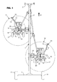
- the machine according to the invention is a swath of plants lying on the ground. It comprises a support structure (1) comprising a central beam (2) which has at its front end a coupling device (3) for attachment to a tractor, not shown, for moving the machine in a direction of advancement (A).
- a support structure (1) comprising a central beam (2) which has at its front end a coupling device (3) for attachment to a tractor, not shown, for moving the machine in a direction of advancement (A).
- A direction of advancement
- the central beam (2) has at its rear end a cross member (4) provided with wheels (5 and 6) which roll on the ground.
- On each side of the central beam (2) is articulated, by means of a substantially horizontal axis (7, 8), an arm (9, 10) which carries a rotor (11, 12) with working tools (13). ) for swathing products such as mown grass or straw on the ground.
- the arms (9 and 10) and the rotors (11 and 12) corresponding are offset in the direction of advance (A).
- the windrowing plants by the most forward rotor (11) can be taken up by the rearmost rotor (12) for the formation of a single largest windrow.
- the central beam (2) could have only one arm and one rotor. It could also have no arms and only one rotor carried directly by the central beam (2).
- the central beam (2) could also comprise, on each side, two offset arms with different lengths and each carrying a rotor. In this case, the machine would have four rotors that would allow it to reach a larger working width.
- the rotors (11 and 12) are substantially identical. Each comprises a casing (14) which is connected to the corresponding arm (9, 10) and which carries a central axis of rotation (15) substantially vertical or slightly inclined towards the front. This axis of rotation (15) has at its lower end a support (16) with carrying wheels (17) located under the rotor (11, 12). These roll on the ground during the work and follow the unevenness of the ground to the rotors (11 and 12).
- the support (16) and the carrying wheels (17) can advantageously slide along the axis of rotation (15) so as to adjust the distance of the working tools (13) from the ground, for example by means of a cylinder.
- a housing (18) On the part of the axis of rotation (15), which extends below the housing (14), is disposed a housing (18). It is mounted on the axis of rotation (15) by means of bearings in order to be rotated.
- the upper side of the housing (18) is provided with a gear wheel located in the housing (14). This wheel meshes with a pinion, which can be connected to a tractor power take-off using intermediate transmission shafts known to those skilled in the art.
- the rotational drive of the rotor (11, 12) could also be carried out with a hydraulic or electric motor.
- the housing (18) supports a multitude of swing arms (19). These extend in the form of spokes relative to the axis of rotation (15), in a plane substantially perpendicular to it.
- the oscillating arms (19) comprise at least two parts, an inner part (20) connected to the housing and an outer part (21) carrying the working tools (13) such as forks.
- the internal parts (20) of the oscillating arms (19) are connected to the housing (18) by one or more bearings so as to be able to turn on themselves.
- On the part of the axis of rotation (15) which is located in the housing (18) is mounted a fixed cam for controlling the oscillating arms (19) during windrowing work.
- each of the oscillating arms (19) has at its end which extends inside the housing (18), a lever with a roller which is guided in a groove of the cam.
- the working tools (13) collect the products especially on the front part of their trajectory and deposit them in the form of a swath in the lateral part of their trajectory.
- Each arm is equipped with a hydraulic cylinder (22, 23) which allows it to pivot about the axis (7, 8).
- Each hydraulic cylinder (22, 23) is articulated with one of its ends on the central beam (2) and with its other end on the corresponding arm (9, 10).
- Each hydraulic cylinder (22, 23) can be double acting so that it can be controlled during elongation and during shortening, and makes it possible to move the corresponding arm (9, 10) between a transport position and a position of job.
- each rotor (11, 12) In the transport position, each rotor (11, 12) extends in a substantially vertical plane or close to the vertical, so that the size of the machine is reduced in width. In the working position, each rotor (11, 12) extends in a substantially horizontal plane.
- the oscillating arms (19) have a circular section.
- oscillating arms (19) of parallelepipedal, oval or other section are possible, this list not being limiting.
- Other more elaborate forms are conceivable, such as a grooved profile or a "lemon" profile known to those skilled in the art.
- the inner portion (20) of the swing arm (19) has an engaging portion (24) while the outer portion (21) has an engaged portion (25).
- the engaging portion (24) is connected to the outer portion (21) and the engaged portion (25) is connected to the inner portion (20).
- the engaging portion (24) extends from the housing (18) some distance along a longitudinal axis (26), which longitudinal axis (26) substantially corresponds to the axis about which the inner portion (20) rotates on it even with respect to the housing (18).
- the engaged portion (25) has an orifice (27) preferably formed by the fact that the outer portion (21) is hollow.
- the outer portion (21) could also be full and the orifice (27) formed by removal of material in the outer portion (21).
- This orifice (27) extends along the longitudinal axis (26) and its diameter is greater than or nearly equal to the outside diameter of the engaging portion (24), so that the latter can freely engage along the longitudinal axis (26) partially to inside the orifice (27).
- the engaging portion (24) and the engaged portion (25) each comprise at least one hole (28, 29, 30, 31) oriented perpendicularly to the longitudinal axis (26).
- the hole or holes (28, 29) of the engaging portion (24) and the hole or holes (30, 31) of the engaged portion (25) are disposed opposite one another or from each other.
- a connecting device (32) connects the engaging portion (24) and the engaged portion (25) therebetween.
- This connecting device (32) comprises at least one threaded element (33, 34) having a geometric axis (35), which threaded element (33, 34) has a shoulder (36, 37).
- the threaded element (33) is constituted by a hexagonal screw and the shoulder (36) is formed by the underside of the head.
- the threaded member (33, 34) has an outer diameter whose value is slightly less than or equal to the diameter of each hole (28, 29, 30, 31). By “slightly lower” is meant that said diameters differ by a value less than one millimeter, for example less than five tenths of a millimeter.
- the threaded element (33, 34) can be manually introduced, without significant effort, through the hole or holes (28, 29) of the engaging portion (24) and through the hole or holes (30, 31) of the engaged portion (25).
- the threaded element (33, 34) is capable of transmitting a part of the rotational torque exerted by the inner part (20) on the outer part (21), by contact with the holes (28, 29, 30, 31). ) with the threaded portion of the threaded element (33, 34). Automatically, introducing the threaded member (33, 34) through the holes (28, 29, 30, 31) orients said portions (24, 25) relative to each other about the axis longitudinal (26).
- the rotation of the inner part (20) of the oscillating arm (19) on itself is transmitted to the outer part (21), and the latter can not move along the longitudinal axis (26) during the pivoting the housing (18) about the axis of rotation (15).
- the connecting device (32) comprises an insert (38).
- the insert (38) may be of metallic material or synthetic and result from machining, molding, cutting or forging operations. It comprises at least one tapping (39, 40) that can cooperate with the threaded element (33, 34).
- the engaging portion (24) has an inner portion (41). The latter is preferably formed by the fact that the inner part (20) of the oscillating arm (19) is hollow. The inner portion (41) could also be formed by removal of material in the inner portion (20).
- the insert (38) is designed such that it can be disposed in the inner portion (41). The shape of the insert (38) corresponds to that of the inner part (41).
- the insert (38) is oriented around the longitudinal axis (26) so that the tapping (39, 40) is directed collinearly to the geometric axis (35) of the threaded element (33, 34) .
- the insert (38) may further be provided with a shoulder (48) that can bear against the engaging portion (24) along the longitudinal axis (26) to facilitate mounting.
- the mounting operations of the swingarm (19) are sequenced as described below.
- the user has the insert (38) in the inner part (41) of the engaging portion (24) so that the thread (s) (39, 40) are substantially opposite the hole or holes (28, 29) of the engaging portion (24). It then partially engages the engaging portion (24) in the orifice (27) of the engaged portion (25), or on the contrary the orifice (27) of the engaged portion (25) on the engaging portion (24), until the hole or holes (30, 31) of the engaged portion (25) are substantially opposite the hole or holes (28, 29) of the engaging portion (24).
- the user introduces the threaded element (33) through the holes (28, 30) or the threaded element (33) through the holes (28, 30) and the threaded element (34) through the holes (29, 31).
- the user screws the threaded element or elements (33, 34) in the tapping (s) (39, 40) of the insert (38) so that the corresponding shoulder or shoulders (36, 37) rest on the portion engaged (25) and that, on the side of at least one of said shoulders (36, 37), the engaged portion (25) is clamped against the engaging portion (24) along the geometric axis (35).
- FIGS. 4 to 9 are directed to alternative embodiments in which the engaging portion (24) and the engaged portion (25) each comprise two holes (28 and 29, 30 and 31) oriented perpendicularly to the longitudinal axis (26).
- the engaging portion (24) and the engaged portion (25) each comprise two holes (28 and 29, 30 and 31) and the holes (28 to 31) are all oriented along the geometric axis (35).
- the dimension of the insert (38), measured along the geometric axis (35), is close to the dimension of the inner part (41) of the engaging portion (24) according to this same axis.
- said dimension of the insert (38) may be slightly smaller, equal to or slightly greater than said dimension of the inner portion (41).
- lightly lower is meant that the insert (38) can be mounted in the inner portion (41) with a positive adjustment clearance and less than a few millimeters, preferably less than one millimeter, for example less than five tenths of a millimeter. This case is illustrated by the figure 4 .
- the insert (38) can be mounted in the inner part (41) with a negative adjustment set, that is to say with tightening, an absolute value lower than tenth of a millimeter, preferably less than five hundredths of a millimeter. This slight tightening allows the mounting of the insert (38) in the inner portion (41) by means of, for example, a mallet.
- the connecting device (32) comprises a single threaded element (33), which passes through two holes (30 and 31) of the engaged portion (25) and two holes (28 and 29) of the engaging portion (24).
- the holes (28 to 31) of each portion (24, 25) are diametrically opposed so that all the holes (28 to 31) of the engaging and engaged portions (24 and 25) are oriented along the geometric axis (35) of the threaded element (33).
- the connecting device (32) additionally comprises a nut (42).
- the threaded element (33) cooperates with the nut (42) pressed on the engaged portion (25), either to tighten the engaging portion (24) and the engaged portion (25) between the insert (38) and the nut (42), or for braking the threaded element (33).
- the figure 8 represents the case where the threaded element (33) cooperates with the nut (42) pressed on the engaged portion (25) to tighten the engaging portion (24) and the engaged portion (25) between the insert (38) and the nut (42).
- all the existing assembly sets, along the geometric axis (35), between the engaged portion (25), the engaging portion (24) and the insert (38) are removed, in the vicinity of both shoulder (36) than nut (42).
- the insert (38) has a dimension slightly smaller than that of the inner portion (41) along the same axis as the geometric axis (35), the tightening of the nut (42) causes slight deformation of the portions (24 and 25) in their elastic domain, in the vicinity of the nut (42).
- the insert (38) then limits the crushing of the engaging and engaged portions (24 and 25), since the engaging portion (24) no longer deforms when it bears on the insert (38). If on the other hand, the insert (38) is mounted in the inner part (41) with zero or negative adjustment play, the tightening of the nut (42) causes, in its vicinity, the only deformation of the portion engaged (25) so that it comes into contact with the engaging portion (24).
- the figure 4 represents the case where the threaded element (33) cooperates with the nut (42) pressed on the engaged portion (25) to brake the threaded element (33).
- the connecting device (32) may comprise two threaded elements (33 and 34) each with a shoulder (36, 37) and each threaded element (33, 34) is screwed into the insert (38) so that the corresponding shoulder (36, 37) is supported on the engaged portion (25).
- the upper threaded member (33) is tightened so that the engaging and engaged portions (24 and 25) are clamped between the upper threaded member (33) and the insert (38).
- the lower threaded member (34) is shown partially tightened.
- the threaded element (34) is essentially intended to transmit a portion of the rotational torque of the inner portion (20) to the outer portion (21), by contact of the threaded portion of said threaded member (34) with the holes (29) and (31). This therefore avoids transmitting all the torque by the single threaded element (33).
- each respective threaded element (33, 34) squeezes the engaging portion (24) and the engaged portion (25) between the insert (38) and its respective shoulder (36, 37), so that no remaining operating clearance along the geometric axis (35).
- the insert (38) then limits the crushing of the engaging and engaged portions (24 and 25).
- the insert (38) is a rigid piece.
- rigid part is meant that the insert (38) undergoes, during clamping of the connecting device (32), deformations which remain negligible compared to those that can undergo the engaging and engaged portions (24 and 25).
- the insert (38) has a thread (39) whose length is smaller than the dimension of the insert (38) measured along the geometric axis (35), that is to say lower than the diameter of the insert (38).
- the insert (38) has two unthreaded holes located in the extension of the tapping (39) and on both sides thereof, the diameter of said holes being greater than the internal diameter of the tapping (39).
- the tapping (39) is substantially centered with respect to the longitudinal axis (26).
- This construction moves the shoulder (36) and the nut (42) away from the first threads engaged with the threaded element (33) at the tapping (39). It reduces the risk of loosening of the threaded element (33) and the nut (42) induced, during operation, by the forces exerted by the engaging and engaged portions (24 and 25) on the threaded element (33). ).
- the variant embodiments of the Figures 6 and 7 use an insert (38) that can extend elastically along the geometric axis (35).
- the insert (38) has, along the geometric axis (35), a dimension before assembly which can be smaller than, equal to or greater than the dimension along this same axis of the inner part (41). ).
- the insert (38) is compressed along the geometric axis (35) so as to engage in the inner portion (41).
- the insert (38) can hold itself in place in the engaging portion (24).
- the elastic insert (38) can lengthen so as to catch up with the play that eventually separates it from the engaging portion (24). Also, the engaging portion (24) deforms very little. Most of the deformations are suffered by the engaged portion (25) to come to press against the engaging portion (24). In the variant embodiments of Figures 6 and 7 , the mechanical stresses on the engaging portion (24), induced by the clamping of the connecting device (32), are particularly low.
- the insert (38) is an S-shaped elastic piece whose upper branch (43) and the lower branch (44) each have their own tapping (39 respectively 40).
- the insert (38) has two halves (45 and 46) distinct movable relative to each other along the geometric axis (35).
- the halves (45 and 46) each comprise a tapping (39 respectively 40) and move away from each other along the geometric axis (35) during tightening of the connecting device (32).
- the two halves (45 and 46) are preferably separated together by means of a centralizer (47) slidably mounted in at least one of the halves (45, 46).
- a centralizer (47) slidably mounted in at least one of the halves (45, 46).
- the invention may also relate to a tedder equipped, instead of said at least one windrowing rotor, at least one fading rotor whose axis of rotation is for example inclined in the direction of advancement. More generally, the invention relates to any haying machine comprising at least one rotor provided with arms carrying working tools.
- a machine may for example be a swather, a press or a self-loader equipped with a pickup finger picking member and which comprises a rotor according to the invention arranged for example to one lateral ends of said pickup member.
- the axis of rotation of the rotor may be arranged in a vertical plane or in a horizontal plane.
Landscapes
- Life Sciences & Earth Sciences (AREA)
- Environmental Sciences (AREA)
- Connection Of Plates (AREA)
- Mutual Connection Of Rods And Tubes (AREA)
- Harvester Elements (AREA)
- Crushing And Pulverization Processes (AREA)
- Surgical Instruments (AREA)
- Harvesting Machines For Root Crops (AREA)
Abstract
Description
- La présente invention se rapporte à un rotor d'une machine de fenaison, le rotor comportant un boîtier entraîné en rotation lors du travail autour d'un axe de rotation dirigé vers le haut et au moins un bras oscillant disposé dans un plan sensiblement perpendiculaire à l'axe de rotation, lequel bras oscillant comportant au moins deux parties, une partie interne liée au boîtier et une partie externe portant des outils de travail, l'une des parties interne et externe comportant une portion engageante pouvant s'engager suivant un axe longitudinal partiellement à l'intérieur d'un orifice d'une portion engagée de l'autre des parties interne et externe, la portion engageante et la portion engagée comportant chacune au moins un trou orienté perpendiculairement à l'axe longitudinal et pouvant être reliées entre elles au moyen d'un dispositif de liaison, lequel dispositif de liaison comportant au moins un élément fileté présentant un axe géométrique et muni d'un épaulement, lequel élément fileté traversant chaque trou des portions engageante et engagée.
- Sur les rotors connus de ce genre, la réalisation du bras oscillant en au moins deux parties, à savoir la partie interne et la partie externe, est justifiée par les contraintes de conditionnement et par les contraintes de réparation du bras en cas de choc au travail. Pour le conditionnement, le rotor est stocké par exemple en palette. Pour minimiser les coûts de transport, il est souhaitable de réduire la taille du rotor. Ainsi, la partie interne reste liée au boîtier tandis que la partie externe est séparée de la partie interne. Pendant le travail d'andainage, les outils de travail peuvent rencontrer des obstacles tels que des pierres, ce qui génère sur le bras d'importantes contraintes mécaniques. En cas de choc violent, le bras est conçu pour que la partie externe plie sous l'effort, tandis que la partie interne reste intacte. Ainsi, il suffit à l'utilisateur de la machine de démonter la partie externe de la partie interne, et de redresser ou remplacer la partie externe, pour remettre la machine en état de fonctionner. Une telle opération est simple et peu coûteuse.
- L'élément fileté, servant à lier les parties interne et externe, est, par exemple, formé par une vis à tête carrée ou hexagonale qui traverse les portions engageante et engagée de part en part, et coopère avec un écrou pour former un boulon. Ce boulon est serré sur la portion engagée de manière à assurer le maintien de la portion engageante à l'intérieur de la portion engagée pendant la rotation du rotor. Le boulon est serré à un couple qui doit d'une part éviter son desserrage inopiné, d'autre part déformer la portion engagée suivant l'axe géométrique pour qu'elle vienne serrer la portion engageante.
- Au montage, il peut exister un jeu important entre les portions, de manière à ce que la portion engageante puisse s'engager facilement à l'intérieur de la portion engagée. Dans ce cas, le serrage du boulon à un couple, permettant d'éviter son desserrage inopiné, n'est pas suffisant pour que la portion engagée vienne serrer la portion engageante. Le rattrapage du jeu important de montage nécessite un couple plus élevé. Or, la plupart du temps, l'utilisateur de la machine emploie l'outillage standard qui se trouve à portée de la main, par exemple une classique clé plate. Un tel outillage ne permet pas de serrer au couple requis avec une bonne précision. Il subsiste alors un jeu de fonctionnement entre les portions, lequel entraîne une usure prématurée de la machine. L'utilisateur peut être tenté de supprimer ce jeu en serrant le boulon avec beaucoup plus de force, en montant par exemple une rallonge sur la clé de serrage. Parce que cette manière de procéder ne permet pas de doser l'effort, les portions engageante et engagée se retrouvent fortement déformées, ce qui rend leur démontage ultérieur difficile voire impossible.
- A l'inverse, un jeu de montage plus faible entre les portions peut être préféré, de sorte qu'un couple de serrage relativement faible, réalisable par l'utilisateur, permette de serrer la portion engagée contre la portion engageante. Dans ce cas, le couple ainsi réalisé est inférieur au couple requis pour éviter un desserrage inopiné du boulon, ce qui peut entraîner sa perte et le détachement de la partie externe du bras oscillant. De ce fait, la sécurité d'utilisation de la machine n'est pas optimale. Au cas où le boulon est serré au couple requis pour éviter ledit desserrage inopiné, la déformation des portions engageante et engagée, qui résulte de ce serrage, est telle qu'elle rend difficile, voire impossible, le coulissement de la portion engageante à l'intérieur de la portion engagée en vue du démontage. L'utilisation de la machine s'en trouve de fait compliquée.
- La présente invention a pour but de proposer un rotor d'une machine de fenaison qui ne présente pas les inconvénients précités.
- A cet effet, une importante caractéristique de l'invention réside dans le fait que le dispositif de liaison comporte un insert avec au moins un taraudage pouvant être disposé dans une partie intérieure de la portion engageante, que l'élément fileté est vissé dans ledit taraudage et que l'épaulement dudit élément fileté s'appuie sur la portion engagée de manière à serrer la portion engagée contre la portion engageante suivant l'axe géométrique.
- Ainsi, le serrage de la portion engagée contre la portion engageante ne requiert pas, ou que peu, de déformation de ces portions. Un jeu de montage important peut donc être envisagé pour garantir un coulissement aisé de la portion engageante dans la portion engagée. Le montage du bras est donc facile. Le serrage par l'utilisateur à un couple, évitant le desserrage inopiné du dispositif de liaison, assure en même temps l'absence de jeu de fonctionnement, suivant l'axe géométrique, entre l'insert, la portion engageante et la portion engagée. L'invention garantit donc simultanément la sécurité d'utilisation de la machine et un fonctionnement durable.
- Selon une caractéristique avantageuse de l'invention, la dimension de l'insert, mesurée suivant l'axe géométrique, est voisine de la dimension de la partie intérieure de la portion engageante suivant ce même axe. En outre, le dispositif de liaison peut comporter un seul élément fileté coopérant avec un écrou, ou encore deux éléments filetés. Il est ainsi possible de supprimer tous les jeux de montage, suivant l'axe géométrique, existant entre la portion engagée, la portion engageante et l'insert, ce qui augmente encore la sécurité d'utilisation et la durabilité de la machine. De plus, l'insert limite l'écrasement des portions engageante et engagée lors du serrage du dispositif de liaison, ce qui facilite leur démontage ultérieur.
- D'autres caractéristiques et avantages de l'invention ressortiront de la description ci-après avec référence aux dessins annexés qui représentent, à titre d'exemple non limitatif, plusieurs formes de réalisation du rotor selon l'invention.
- Sur ces dessins :
- la
figure 1 représente une vue de dessus d'une machine de fenaison conforme à l'invention, comportant au moins un rotor muni de bras oscillants; - la
figure 2 représente une vue partielle en perspective d'un rotor conforme à l'invention, un seul bras oscillant étant représenté en totalité; - la
figure 3 représente une vue en coupe partielle d'une première variante de réalisation d'un dispositif de liaison conforme à l'invention; - la
figure 4 représente une vue de la première variante de réalisation du dispositif de liaison suivant la coupe IV-IV de lafigure 2 ; - la
figure 5 représente une vue d'une deuxième variante de réalisation du dispositif de liaison suivant la coupe V-V de lafigure 2 ; - la
figure 6 représente une vue d'une troisième variante de réalisation du dispositif de liaison suivant la coupe VI-VI de lafigure 2 ; - la
figure 7 représente une vue d'une quatrième variante de réalisation du dispositif de liaison suivant la coupe VII-VII de lafigure 2 ; - la
figure 8 représente une autre vue de la première variante de réalisation du dispositif de liaison suivant la coupe VIII-VIII de lafigure 2 ; - la
figure 9 représente une autre vue de la deuxième variante de réalisation du dispositif de liaison suivant la coupe IX-IX de lafigure 2 ; - Telle qu'elle est représentée sur la
figure 1 , la machine selon l'invention est une andaineuse de végétaux couchés sur le sol. Elle comporte une structure porteuse (1) comprenant une poutre centrale (2) qui possède à son extrémité avant un dispositif d'attelage (3) pour l'accrocher à un tracteur, non représenté, permettant de déplacer la machine dans une direction d'avancement (A). Dans la suite de la description, la notion « avant » est définie par rapport à la direction d'avancement (A). - La poutre centrale (2) possède à son extrémité arrière une traverse (4) munie de roues (5 et 6) qui roulent sur le sol. Sur chaque côté de la poutre centrale (2) est articulé, au moyen d'un axe (7, 8) sensiblement horizontal, un bras (9, 10) qui porte un rotor (11, 12) avec des outils de travail (13) destinés à andainer des produits tels que de l'herbe ou de la paille fauchée se trouvant sur le sol. Dans l'exemple représenté, les bras (9 et 10) et les rotors (11 et 12) correspondant sont décalés dans la direction d'avancement (A). Les végétaux andainés par le rotor (11) le plus en avant peuvent être repris par le rotor (12) le plus en arrière pour la formation d'un andain unique de plus grand volume.
- La poutre centrale (2) pourrait ne comporter qu'un seul bras et qu'un seul rotor. Elle pourrait aussi ne comporter aucun bras et qu'un seul rotor porté directement par la poutre centrale (2). La poutre centrale (2) pourrait aussi comporter, de chaque côté, deux bras décalés avec des longueurs différentes et portant chacun un rotor. Dans ce cas, la machine comporterait quatre rotors qui lui permettraient d'atteindre une largeur de travail plus importante.
- Les rotors (11 et 12) sont sensiblement identiques. Chacun comporte un carter (14) qui est lié au bras (9, 10) correspondant et qui porte un axe de rotation (15) central sensiblement vertical ou légèrement incliné vers l'avant. Cet axe de rotation (15) comporte à son extrémité inférieure un support (16) avec des roues porteuses (17) situées sous le rotor (11, 12). Ces dernières roulent sur le sol durant le travail et font suivre les dénivellations du sol aux rotors (11 et 12). Le support (16) et les roues porteuses (17) peuvent avantageusement coulisser le long de l'axe de rotation (15) de manière à régler la distance des outils de travail (13) par rapport au sol, par exemple au moyen d'un vérin.
- Sur la partie de l'axe de rotation (15), qui s'étend en-dessous du carter (14), est disposé un boîtier (18). Celui-ci est monté sur l'axe de rotation (15) à l'aide de roulements afin de pouvoir être entraîné en rotation. Le côté supérieur du boîtier (18) est muni d'une roue dentée qui se situe dans le carter (14). Cette roue engrène avec un pignon, lequel peut être relié à une prise de force du tracteur à l'aide d'arbres de transmission intermédiaires connus de l'homme de l'art. L'entraînement en rotation du rotor (11, 12) pourrait également être effectué avec un moteur hydraulique ou électrique. Le boîtier (18) supporte une multitude de bras oscillants (19). Ceux-ci s'étendent en forme de rayons par rapport à l'axe de rotation (15), dans un plan sensiblement perpendiculaire à celui-ci. Les bras oscillants (19) comportent au moins deux parties, une partie interne (20) liée au boîtier et une partie externe (21) portant les outils de travail (13) tels que des fourches. Les parties internes (20) des bras oscillants (19) sont liées au boîtier (18) par un ou plusieurs paliers de manière à pouvoir tourner sur elles-mêmes. Sur la partie de l'axe de rotation (15) qui se situe dans le boîtier (18) est montée une came fixe destinée à commander les bras oscillants (19) durant le travail d'andainage. Pour cela, chacun des bras oscillants (19) possède à son extrémité qui s'étend à l'intérieur du boîtier (18), un levier avec un galet qui est guidé dans une gorge de la came. Au travail, les outils de travail (13) ramassent les produits notamment sur la partie avant de leur trajectoire et les déposent sous la forme d'un andain dans la partie latérale de leur trajectoire.
- Chaque bras est équipé d'un vérin hydraulique (22, 23) qui permet de le pivoter autour de l'axe (7, 8). Chaque vérin hydraulique (22, 23) est articulé avec une de ses extrémités sur la poutre centrale (2) et avec son autre extrémité sur le bras (9, 10) correspondant. Chaque vérin hydraulique (22, 23) peut être à double effet de manière à pouvoir être commandé lors de l'allongement et lors du raccourcissement, et permet de déplacer le bras (9, 10) correspondant entre une position de transport et une position de travail. Dans la position de transport, chaque rotor (11, 12) s'étend dans un plan sensiblement vertical ou proche de la verticale, de sorte que l'encombrement de la machine est réduit en largeur. Dans la position de travail, chaque rotor (11, 12) s'étend dans un plan sensiblement horizontal.
- Dans les variantes de réalisation décrites, les bras oscillants (19) présentent une section circulaire. Toutefois, des bras oscillants (19) de section parallélépipédique, ovale ou autre sont possibles, cette liste n'étant pas limitative. D'autres formes plus élaborées sont envisageables, telles qu'un profil rainuré ou un profil « en citron » connu de l'homme de l'art.
- Tel que cela est représenté notamment sur la
figure 3 , la partie interne (20) du bras oscillant (19) comporte une portion engageante (24) tandis que la partie externe (21) comporte une portion engagée (25). Suivant une variante de réalisation non représentée, il serait possible que la portion engageante (24) soit liée à la partie externe (21) et que la portion engagée (25) soit liée à la partie interne (20). On distingue sur lafigure 3 que la portion engageante (24) s'étend depuis le boîtier (18) sur quelque distance suivant un axe longitudinal (26), lequel axe longitudinal (26) correspond sensiblement à l'axe autour duquel la partie interne (20) tourne sur elle-même par rapport au boîtier (18). La portion engagée (25) comporte un orifice (27) formé de préférence par le fait que la partie externe (21) est creuse. La partie externe (21) pourrait aussi être pleine et l'orifice (27) formé par enlèvement de matière dans la partie externe (21). Cet orifice (27) s'étend suivant l'axe longitudinal (26) et son diamètre est supérieur ou quasiment égal au diamètre extérieur de la portion engageante (24), de sorte que cette dernière puisse s'engager librement suivant l'axe longitudinal (26) partiellement à l'intérieur de l'orifice (27). Tel que cela ressort des différentes variantes de réalisation illustrées sur lesfigures 4 à 9 , la portion engageante (24) et la portion engagée (25) comportent chacune au moins un trou (28, 29, 30, 31) orienté perpendiculairement à l'axe longitudinal (26). Le ou les trous (28, 29) de la portion engageante (24) et le ou les trous (30, 31) de la portion engagée (25) sont disposés en face l'un de l'autre ou les uns des autres. Un dispositif de liaison (32) permet de relier la portion engageante (24) et la portion engagée (25) entre elles. Ce dispositif de liaison (32) comporte au moins un élément fileté (33, 34) présentant un axe géométrique (35), lequel élément fileté (33, 34) comporte un épaulement (36, 37). Dans la variante de réalisation de lafigure 4 , l'élément fileté (33) est constitué par une vis à tête hexagonale et l'épaulement (36) est formé par la face inférieure de la tête. L'élément fileté (33, 34) présente un diamètre extérieur dont la valeur est légèrement inférieure ou égale au diamètre de chaque trou (28, 29, 30, 31). Par « légèrement inférieure », on entend que lesdits diamètres diffèrent d'une valeur inférieure à un millimètre, par exemple inférieure à cinq dixièmes de millimètres. De cette manière, l'élément fileté (33, 34) peut être introduit manuellement, sans effort important, à travers le ou les trous (28, 29) de la portion engageante (24) et à travers le ou les trous (30, 31) de la portion engagée (25). De plus, l'élément fileté (33, 34) est susceptible de transmettre une partie du couple de rotation exercé par la partie interne (20) sur la partie externe (21), par contact des trous (28, 29, 30, 31) avec la portion filetée de l'élément fileté (33, 34). Automatiquement, l'introduction de l'élément fileté (33, 34) à travers les trous (28, 29, 30, 31) oriente lesdites portions (24, 25) l'une par rapport à l'autre autour de l'axe longitudinal (26). De plus, la rotation de la partie interne (20) du bras oscillant (19) sur elle-même est transmise à la partie externe (21), et cette dernière ne peut pas se déplacer suivant l'axe longitudinal (26) lors du pivotement du boîtier (18) autour de l'axe de rotation (15). - Selon une caractéristique importante de l'invention, le dispositif de liaison (32) comporte un insert (38). L'insert (38) peut être en matière métallique ou synthétique et résulter d'opérations d'usinage, de moulage, de découpage ou de forgeage. Il comporte au moins un taraudage (39, 40) pouvant coopérer avec l'élément fileté (33, 34). La portion engageante (24) comporte une partie intérieure (41). Cette dernière est formée de préférence par le fait que la partie interne (20) du bras oscillant (19) est creuse. La partie intérieure (41) pourrait aussi être formée par enlèvement de matière dans la partie interne (20). L'insert (38) est conçu de telle sorte qu'il puisse être disposé dans la partie intérieure (41). La forme de l'insert (38) correspond à celle de la partie intérieure (41). L'insert (38) est orienté autour de l'axe longitudinal (26) de manière à ce que le taraudage (39, 40) soit dirigé colinéairement à l'axe géométrique (35) de l'élément fileté (33, 34). Ainsi qu'il ressort de la
figure 3 , l'insert (38) peut de plus être muni d'un épaulement (48) pouvant s'appuyer contre la portion engageante (24) suivant l'axe longitudinal (26) afin de faciliter le montage. - Les opérations de montage du bras oscillant (19) sont séquencées de la manière décrite comme suit. L'utilisateur dispose l'insert (38) dans la partie intérieure (41) de la portion engageante (24) pour que le ou les taraudages (39, 40) soient sensiblement en face du ou des trous (28, 29) de la portion engageante (24). Il engage ensuite partiellement la portion engageante (24) dans l'orifice (27) de la portion engagée (25), ou au contraire l'orifice (27) de la portion engagée (25) sur la portion engageante (24), jusqu'à ce que le ou les trous (30, 31) de la portion engagée (25) soient sensiblement en face du ou des trous (28, 29) de la portion engageante (24). Puis, l'utilisateur introduit l'élément fileté (33) à travers les trous (28, 30) ou bien l'élément fileté (33) à travers les trous (28, 30) et l'élément fileté (34) à travers les trous (29, 31). L'utilisateur visse ensuite le ou les éléments filetés (33, 34) dans le ou les taraudages (39, 40) de l'insert (38) pour que le ou les épaulements (36, 37) correspondants s'appuient sur la portion engagée (25) et que, du côté d'au moins un desdits épaulements (36, 37), la portion engagée (25) soit serrée contre la portion engageante (24) suivant l'axe géométrique (35).
- Les
figures 4 à 9 s'adressent à des variantes de réalisation dans lesquelles la portion engageante (24) et la portion engagée (25) comportent chacune deux trous (28 et 29, 30 et 31) orientés perpendiculairement à l'axe longitudinal (26). - De préférence, la portion engageante (24) et la portion engagée (25) comportent chacune deux trous (28 et 29, 30 et 31) et les trous (28 à 31) sont tous orientés suivant l'axe géométrique (35).
- Selon une caractéristique avantageuse de l'invention, la dimension de l'insert (38), mesurée suivant l'axe géométrique (35), est voisine de la dimension de la partie intérieure (41) de la portion engageante (24) suivant ce même axe. Ceci signifie que ladite dimension de l'insert (38) peut être légèrement inférieure, égale ou légèrement supérieure à ladite dimension de la partie intérieure (41). Par « légèrement inférieure », on entend que l'insert (38) peut être monté dans la partie intérieure (41) avec un jeu d'ajustement positif et inférieur à quelques millimètres, de préférence inférieur à un millimètre, par exemple inférieur à cinq dixièmes de millimètres. Ce cas est illustré par la
figure 4 . Par « légèrement supérieure », on entend que l'insert (38) peut être monté dans la partie intérieure (41) avec un jeu d'ajustement négatif, c'est-à-dire avec serrage, d'une valeur absolue inférieure au dixième de millimètre, de préférence inférieure à cinq centièmes de millimètre. Ce léger serrage autorise le montage de l'insert (38) dans la partie intérieure (41) au moyen, par exemple, d'un maillet. - Dans la variante de réalisation de la
figure 4 , le dispositif de liaison (32) comporte un seul élément fileté (33), lequel traverse deux trous (30 et 31) de la portion engagée (25) et deux trous (28 et 29) de la portion engageante (24). Les trous (28 à 31) de chaque portion (24, 25) sont diamétralement opposés de sorte que tous les trous (28 à 31) des portions engageante et engagée (24 et 25) soient orientés suivant l'axe géométrique (35) de l'élément fileté (33). Le dispositif de liaison (32) comporte en sus un écrou (42). L'élément fileté (33) coopère avec l'écrou (42) appuyé sur la portion engagée (25), soit pour serrer la portion engageante (24) et la portion engagée (25) entre l'insert (38) et l'écrou (42), soit pour freiner l'élément fileté (33). - La
figure 8 représente le cas où l'élément fileté (33) coopère avec l'écrou (42) appuyé sur la portion engagée (25) pour serrer la portion engageante (24) et la portion engagée (25) entre l'insert (38) et l'écrou (42). Dans ce cas, tous les jeux de montage existant, suivant l'axe géométrique (35), entre la portion engagée (25), la portion engageante (24) et l'insert (38), sont supprimés, au voisinage tant de l'épaulement (36) que de l'écrou (42). De plus, si l'insert (38) présente suivant l'axe géométrique (35), une dimension légèrement inférieure à celle de la partie intérieure (41) mesurée suivant le même axe, le serrage de l'écrou (42) entraîne une légère déformation des portions (24 et 25) dans leur domaine élastique, au voisinage de l'écrou (42). L'insert (38) limite alors l'écrasement des portions engageante et engagée (24 et 25), puisque la portion engageante (24) ne se déforme plus lorsqu'elle vient en appui sur l'insert (38). Si par contre, l'insert (38) est monté dans la partie intérieure (41) avec un jeu d'ajustement nul ou négatif, le serrage de l'écrou (42) entraîne, dans son voisinage, la seule déformation de la portion engagée (25) pour que celle-ci vienne en contact avec la portion engageante (24). - La
figure 4 représente le cas où l'élément fileté (33) coopère avec l'écrou (42) appuyé sur la portion engagée (25) pour freiner l'élément fileté (33). Dans ce cas, une partie des jeux de montage existant, suivant l'axe géométrique (35), entre l'insert (38), la portion engagée (25), la portion engageante (24) et l'écrou (42), subsiste, et l'écrou joue le rôle de contre-écrou empêchant un desserrage intempestif de l'élément fileté (33) à l'intérieur du taraudage (39) de l'insert (38). - Dans les deux cas qui viennent d'être cités, l'emploi de l'écrou (42) augmente la sécurité d'utilisation et la durabilité de la machine.
- Ainsi qu'il ressort des
figures 5 à 7 , le dispositif de liaison (32) peut comporter deux éléments filetés (33 et 34) avec chacun un épaulement (36, 37) et chaque élément fileté (33, 34) est vissé dans l'insert (38) de sorte que l'épaulement (36, 37) correspondant s'appuie sur la portion engagée (25). Sur ces figures, l'élément fileté (33) supérieur est serré de manière à ce que les portions engageante et engagée (24 et 25) soient serrées entre l'élément fileté (33) supérieur et l'insert (38). - Sur ces figures, l'élément fileté (34) inférieur est représenté partiellement serré. Dans ce cas, l'élément fileté (34) vise essentiellement à transmettre une partie du couple de rotation de la partie interne (20) vers la partie externe (21), par contact de la portion filetée dudit élément fileté (34) avec les trous (29) et (31). Cela évite donc de transmettre tout le couple de rotation par le seul élément fileté (33).
- Tel que cela est représenté sur la
figure 9 , l'élément fileté (34) inférieur est serré davantage, à l'instar de l'élément fileté (33) supérieur. Ainsi, chaque élément fileté (33, 34) respectif serre la portion engageante (24) et la portion engagée (25) entre l'insert (38) et son épaulement (36, 37) respectif, de sorte qu'il ne subsiste aucun jeu de fonctionnement suivant l'axe géométrique (35). L'insert (38) limite alors l'écrasement des portions engageante et engagée (24 et 25). - Dans les variantes de réalisation des
figures 4 et 5 , l'insert (38) est une pièce rigide. Par pièce rigide, on entend que l'insert (38) subit, lors du serrage du dispositif de liaison (32), des déformations qui restent négligeables par rapport à celles que peuvent subir les portions engageante et engagée (24 et 25). Dans la variante de réalisation de lafigure 4 , l'insert (38) comporte un taraudage (39) dont la longueur est plus faible que la dimension de l'insert (38) mesurée suivant l'axe géométrique (35), c'est-à-dire plus faible que le diamètre de l'insert (38). L'insert (38) comporte deux trous non taraudés situés dans le prolongement du taraudage (39) et de part et d'autre de celui-ci, le diamètre desdits trous étant supérieur au diamètre intérieur du taraudage (39). De préférence, le taraudage (39) est sensiblement centré par rapport à l'axe longitudinal (26). Cette construction éloigne l'épaulement (36) et l'écrou (42) des premiers filets en prise de l'élément fileté (33) au niveau du taraudage (39). Elle réduit le risque de desserrage de l'élément fileté (33) et de l'écrou (42) induit, lors du fonctionnement, par les efforts exercés par les portions engageante et engagée (24 et 25) sur l'élément fileté (33). - Les variantes de réalisation des
figures 6 et 7 font appel à un insert (38) pouvant s'allonger élastiquement suivant l'axe géométrique (35). Dans ces variantes, l'insert (38) présente, suivant l'axe géométrique (35), une dimension avant montage qui peut être plus faible que, égale à ou plus grande que la dimension suivant ce même axe de la partie intérieure (41). Dans le cas où sa dimension avant montage est plus grande, l'insert (38) se comprime suivant l'axe géométrique (35) de manière à pouvoir s'engager dans la partie intérieure (41). Ainsi, l'insert (38) peut tenir de lui-même en place dans la portion engageante (24). Après avoir serré l'élément fileté (33) supérieur de sorte que la portion engageante (24) et la portion engagée (25) soient serrées entre l'insert (38) et l'élément fileté (33) supérieur, l'utilisateur vient serrer l'élément fileté (34) inférieur. Lors du serrage de ce dernier, l'insert (38) élastique peut s'allonger de manière à rattraper le jeu qui le sépare éventuellement de la portion engageante (24). Aussi, la portion engageante (24) se déforme très peu. L'essentiel des déformations est subi par la portion engagée (25) pour venir se plaquer contre la portion engageante (24). Dans les variantes de réalisation desfigures 6 et 7 , les contraintes mécaniques sur la portion engageante (24), induites par le serrage du dispositif de liaison (32), sont donc particulièrement faibles. - Dans la variante de réalisation de la
figure 6 , l'insert (38) est une pièce élastique en forme de S dont la branche supérieure (43) et la branche inférieure (44) comportent chacune leur propre taraudage (39 respectivement 40). - Dans la variante de réalisation de la
figure 7 , l'insert (38) comporte deux moitiés (45 et 46) distinctes pouvant se déplacer l'une par rapport à l'autre suivant l'axe géométrique (35). Les moitiés (45 et 46) comportent chacune un taraudage (39 respectivement 40) et s'éloignent l'une de l'autre suivant l'axe géométrique (35) lors du serrage du dispositif de liaison (32). - Dans cette même variante, les deux moitiés (45 et 46) distinctes sont de préférence assemblées au moyen d'un centreur (47) monté coulissant dans au moins une des moitiés (45, 46). Une telle construction facilite la mise en place de l'insert (38) dans la partie intérieure (41) de la portion engageante (24).
- La description précédente se rapporte à une andaineuse de végétaux couchés sur le sol munie d'au moins un rotor d'andainage dont l'axe de rotation est de préférence vertical en position de travail. Toutefois, l'invention peut aussi se rapporter à une faneuse munie, en lieu et place dudit au moins un rotor d'andainage, d'au moins un rotor de fanage dont l'axe de rotation est par exemple incliné dans la direction d'avancement. Plus généralement, l'invention concerne toute machine de fenaison comportant au moins un rotor muni de bras portant des outils de travail. Une telle machine peut par exemple être une andaineuse, une presse ou une auto-chargeuse munie d'un organe de ramassage à doigts du type « pick-up » et qui comporte un rotor conforme à l'invention disposé par exemple à l'une des extrémités latérales dudit organe de ramassage. L'axe de rotation du rotor peut être disposé dans un plan vertical ou dans un plan horizontal.
- Il est bien évident que l'invention n'est pas limitée aux formes de réalisation décrites ci-dessus et représentées sur les figures annexées. Des modifications restent possibles, notamment en ce qui concerne la constitution ou le nombre des divers éléments ou par substitution d'équivalents techniques, sans pour autant sortir du domaine de protection.
Claims (17)
- Rotor d'une machine de fenaison, le rotor (11, 12) comportant un boîtier (18) entraîné en rotation lors du travail autour d'un axe de rotation (15) dirigé vers le haut et au moins un bras oscillant (19) disposé dans un plan sensiblement perpendiculaire à l'axe de rotation (15), lequel bras oscillant (19) comportant au moins deux parties, une partie interne (20) liée au boîtier (18) et une partie externe (21) portant des outils de travail (13), l'une des parties interne et externe (20 et 21) comportant une portion engageante (24) pouvant s'engager suivant un axe longitudinal (26) partiellement à l'intérieur d'un orifice (27) d'une portion engagée (25) de l'autre des parties interne et externe (20 et 21), la portion engageante (24) et la portion engagée (25) comportant chacune au moins un trou (28, 29, 30, 31) orienté perpendiculairement à l'axe longitudinal (26) et pouvant être reliées entre elles au moyen d'un dispositif de liaison (32), lequel dispositif de liaison (32) comportant au moins un élément fileté (33, 34) présentant un axe géométrique (35) et muni d'un épaulement (36, 37), lequel élément fileté (33, 34) traversant chaque trou (28, 29, 30, 31) des portions engageante et engagée (24 et 25), caractérisé en ce que le dispositif de liaison (32) comporte un insert (38) avec au moins un taraudage (39, 40) pouvant être disposé dans une partie intérieure (41) de la portion engageante (24), que l'élément fileté (33, 34) est vissé dans le taraudage (39, 40) et que l'épaulement (36, 37) s'appuie sur la portion engagée (25) de manière à serrer la portion engagée (25) contre la portion engageante (24) suivant l'axe géométrique (35).
- Rotor selon la revendication 1, caractérisé en ce que l'élément fileté (33, 34) présente un diamètre extérieur dont la valeur est légèrement inférieure ou égale au diamètre de chaque trou (28, 29, 30, 31) des portions engageante et engagée (24 et 25).
- Rotor selon la revendication 1 ou 2, caractérisé en ce que la portion engageante (24) et la portion engagée (25) comportent chacune deux trous (28 et 29, 30 et 31) orientés perpendiculairement à l'axe longitudinal (26).
- Rotor selon la revendication 3, caractérisé en ce que la portion engageante (24) et la portion engagée (25) comportent chacune deux trous (28 et 29, 30 et 31) et que les trous (28 à 31) sont tous orientés suivant l'axe géométrique (35).
- Rotor selon l'une quelconque des revendications 1 à 4, caractérisé en ce que suivant l'axe géométrique (35), la dimension de l'insert (38) est voisine de la dimension de la partie intérieure (41) de la portion engageante (24).
- Rotor selon la revendication 4 ou 5, caractérisé en ce que le dispositif de liaison (32) comporte un seul élément fileté (33) et un écrou (42), que l'élément fileté (33) traverse les trous (28 et 29) de la portion engageante (24) et les trous (30 et 31) de la portion engagée (25) et coopère avec l'écrou (42) appuyé sur la portion engagée (25) pour serrer la portion engageante (24) et la portion engagée (25) entre l'insert (38) et l'écrou (42).
- Rotor selon la revendication 4 ou 5, caractérisé en ce que le dispositif de liaison (32) comporte un seul élément fileté (33) et un écrou (42), que l'élément fileté (33) traverse les trous (28 et 29) de la portion engageante (24) et les trous (30 et 31) de la portion engagée (25) et coopère avec l'écrou (42) appuyé sur la portion engagée (25) pour freiner l'élément fileté (33).
- Rotor selon la revendication 6 ou 7, caractérisé en ce que le taraudage (39) présente une longueur plus faible que la dimension de l'insert (38) mesurée suivant l'axe géométrique (35).
- Rotor selon l'une quelconque des revendications 3 à 5, caractérisé en ce que le dispositif de liaison (32) comporte deux éléments filetés (33 et 34) avec chacun un épaulement (36, 37) et que chaque élément fileté (33, 34) est vissé dans l'insert (38) de sorte que l'épaulement (36, 37) correspondant s'appuie sur la portion engagée (25).
- Rotor selon l'une quelconque des revendications 1 à 9, caractérisé en ce que l'insert (38) est une pièce rigide.
- Rotor selon la revendication 4 ou 5, caractérisé en ce que l'insert (38) peut s'allonger élastiquement suivant l'axe géométrique (35).
- Rotor selon la revendication 11, caractérisé en ce que l'insert (38) est une pièce élastique en forme de S.
- Rotor selon la revendication 11, caractérisé en ce que l'insert (38) comporte deux moitiés (45 et 46) distinctes pouvant se déplacer l'une par rapport à l'autre suivant l'axe géométrique (35).
- Rotor selon la revendication 13, caractérisé en ce que les deux moitiés (45 et 46) distinctes sont assemblées au moyen d'un centreur (47) monté coulissant dans au moins une des moitiés (45 et 46).
- Rotor selon l'une quelconque des revendications 9 à 14, caractérisé en ce que chaque élément fileté (33, 34) respectif serre la portion engageante (24) et la portion engagée (25) entre l'insert (38) et son épaulement (36, 37) respectif.
- Rotor selon l'une quelconque des revendications 1 à 15, caractérisé en ce que l'insert (38) comporte un épaulement (48) pouvant s'appuyer contre la portion engageante (24) suivant l'axe longitudinal (26).
- Machine de fenaison comportant au moins un rotor (11, 12) selon l'une quelconque des revendications 1 à 16.
Priority Applications (2)
| Application Number | Priority Date | Filing Date | Title |
|---|---|---|---|
| SI201330094T SI2633748T1 (sl) | 2012-02-29 | 2013-02-13 | Stroj za spravilo sena |
| PL13155037T PL2633748T3 (pl) | 2012-02-29 | 2013-02-13 | Maszyna do sianokosów |
Applications Claiming Priority (1)
| Application Number | Priority Date | Filing Date | Title |
|---|---|---|---|
| FR1251835A FR2987223B1 (fr) | 2012-02-29 | 2012-02-29 | Rotor d'une machine de fenaison muni de bras en deux parties reliees par un dispositif de liaison perfectionne |
Publications (2)
| Publication Number | Publication Date |
|---|---|
| EP2633748A1 true EP2633748A1 (fr) | 2013-09-04 |
| EP2633748B1 EP2633748B1 (fr) | 2015-09-16 |
Family
ID=47681799
Family Applications (1)
| Application Number | Title | Priority Date | Filing Date |
|---|---|---|---|
| EP13155037.8A Active EP2633748B1 (fr) | 2012-02-29 | 2013-02-13 | Machine de fenaison |
Country Status (12)
| Country | Link |
|---|---|
| US (1) | US8915054B2 (fr) |
| EP (1) | EP2633748B1 (fr) |
| CN (1) | CN103291708B (fr) |
| AU (1) | AU2013201166B2 (fr) |
| BR (1) | BR102013004807B1 (fr) |
| CA (1) | CA2808507C (fr) |
| DK (1) | DK2633748T3 (fr) |
| FR (1) | FR2987223B1 (fr) |
| PL (1) | PL2633748T3 (fr) |
| RU (1) | RU2606830C2 (fr) |
| SI (1) | SI2633748T1 (fr) |
| UA (1) | UA111165C2 (fr) |
Families Citing this family (5)
| Publication number | Priority date | Publication date | Assignee | Title |
|---|---|---|---|---|
| FR3046025B1 (fr) * | 2015-12-29 | 2018-01-19 | Kuhn Sa | Machine de fenaison avec un moyen de protection contre les projections |
| CN105474886A (zh) * | 2016-01-18 | 2016-04-13 | 中外合资沃得重工(中国)有限公司 | 二自由度搂草臂驱动装置 |
| GB201811406D0 (en) * | 2018-07-12 | 2018-08-29 | Agco Feucht Gmbh | Towed agricultural implement |
| USD958197S1 (en) * | 2020-08-20 | 2022-07-19 | Kuhn Sas | Tedder plate |
| USD959504S1 (en) * | 2021-02-16 | 2022-08-02 | Kuhn Sas | Tedder arm |
Citations (4)
| Publication number | Priority date | Publication date | Assignee | Title |
|---|---|---|---|---|
| GB1278450A (en) * | 1968-12-06 | 1972-06-21 | Bucher Guyer Ag Masch | Improvements in or relating to haymaking machines |
| FR2386248A1 (fr) * | 1977-04-08 | 1978-11-03 | Walle Philippe Van De | Machine servant a la recolte du foin et a la formation d'andains |
| DE19746216A1 (de) * | 1997-10-21 | 1999-04-29 | Krone Bernhard Gmbh Maschf | Kreiselrechen für eine Heuwerbungsmaschine |
| DE202009014404U1 (de) * | 2008-11-07 | 2009-12-24 | Lely Patent N.V. | Landwirtschaftliches Rechgerät |
Family Cites Families (20)
| Publication number | Priority date | Publication date | Assignee | Title |
|---|---|---|---|---|
| DE1507324C3 (de) * | 1966-06-24 | 1978-05-11 | Maschinenfabrik Fahr Ag, 7702 Gottmadingen | Kreiselzettwender |
| CH458823A (de) * | 1967-07-14 | 1968-06-30 | Bucher Guyer Ag Masch | Heuerntemaschine |
| US3648448A (en) * | 1970-08-11 | 1972-03-14 | Fahr Ag Maschf | Hay rake, tedder or crop-turning implement |
| US3664105A (en) * | 1971-05-24 | 1972-05-23 | Sperry Rand Corp | Rake-tedding device |
| FR2339330A1 (fr) * | 1976-01-30 | 1977-08-26 | Kuhn Sa | Machine de fenaison pour le fanage et pour l'andainage |
| FR2450554B1 (fr) * | 1979-03-09 | 1985-07-05 | Belrecolt Sa | Perfectionnement aux machines de fenaison combinees |
| US4253509A (en) * | 1979-04-06 | 1981-03-03 | Collet James R | Theft deterrent locking nut |
| SU1218984A1 (ru) * | 1984-01-10 | 1986-03-23 | Фрунзенский Конструкторско-Технологический Институт По Кормоуборочным Машинам | Грабли-ворошилка |
| FR2613177B1 (fr) * | 1987-04-01 | 1991-06-28 | Kuhn Sa | Machine de fenaison |
| SU1461386A1 (ru) * | 1987-06-10 | 1989-02-28 | Фрунзенский Конструкторско-Технологический Институт По Кормоуборочным Машинам | Сеноуборочна машина |
| SU1521354A1 (ru) * | 1987-10-21 | 1989-11-15 | Фрунзенский Конструкторско-Технологический Институт По Кормоуборочным Машинам | Грабли-ворошилка |
| FR2632810B2 (fr) * | 1987-11-17 | 1991-08-30 | Kuhn Sa | Machine de fenaison avec au moins une roue rateleuse equipee de bras porte-outils commandes |
| DK171109B1 (da) * | 1989-01-20 | 1996-06-17 | Fransgaards Maskinfab As | Maskine til spredning, vending og sammenrivning af hø, halm og lignende materialer |
| FR2644320B1 (fr) * | 1989-03-20 | 1992-05-07 | Kuhn Sa | Machine agricole avec au moins un rotor pour deplacer des produits se trouvant sur le sol |
| FR2648310B1 (fr) * | 1989-06-16 | 1991-09-20 | Kuhn Sa | Machine agricole pour l'andainage, comportant des bras porte-outils repliables |
| US5377482A (en) * | 1993-09-03 | 1995-01-03 | Miller-St. Nazianz, Inc. | Hydraulic lift rotary rake |
| FR2719443B1 (fr) * | 1994-05-04 | 1996-07-05 | Kuhn Sa | Machine de fenaison, notamment un andaineur de fourrage. |
| FR2722365B1 (fr) * | 1994-07-13 | 1996-09-20 | Kuhn Sa Societe Anonyme | Machine de fenaison, notamment une andaineuse de vegetaux a bras porte-fourches commandes |
| DE19502710C1 (de) * | 1995-01-28 | 1996-08-22 | Krone Bernhard Gmbh Maschf | Kreiselrechen für eine Heuwerbungsmaschine |
| US6272826B1 (en) * | 1999-04-29 | 2001-08-14 | Sitrex S.R.L. | Method and apparatus for positioning a hay rake |
-
2012
- 2012-02-29 FR FR1251835A patent/FR2987223B1/fr not_active Expired - Fee Related
-
2013
- 2013-02-13 EP EP13155037.8A patent/EP2633748B1/fr active Active
- 2013-02-13 PL PL13155037T patent/PL2633748T3/pl unknown
- 2013-02-13 SI SI201330094T patent/SI2633748T1/sl unknown
- 2013-02-13 DK DK13155037.8T patent/DK2633748T3/en active
- 2013-02-20 CA CA2808507A patent/CA2808507C/fr not_active Expired - Fee Related
- 2013-02-26 UA UAA201302448A patent/UA111165C2/uk unknown
- 2013-02-27 RU RU2013108872A patent/RU2606830C2/ru active
- 2013-02-28 BR BR102013004807-0A patent/BR102013004807B1/pt not_active IP Right Cessation
- 2013-02-28 AU AU2013201166A patent/AU2013201166B2/en not_active Ceased
- 2013-02-28 CN CN201310062455.1A patent/CN103291708B/zh not_active Expired - Fee Related
- 2013-02-28 US US13/780,268 patent/US8915054B2/en active Active
Patent Citations (4)
| Publication number | Priority date | Publication date | Assignee | Title |
|---|---|---|---|---|
| GB1278450A (en) * | 1968-12-06 | 1972-06-21 | Bucher Guyer Ag Masch | Improvements in or relating to haymaking machines |
| FR2386248A1 (fr) * | 1977-04-08 | 1978-11-03 | Walle Philippe Van De | Machine servant a la recolte du foin et a la formation d'andains |
| DE19746216A1 (de) * | 1997-10-21 | 1999-04-29 | Krone Bernhard Gmbh Maschf | Kreiselrechen für eine Heuwerbungsmaschine |
| DE202009014404U1 (de) * | 2008-11-07 | 2009-12-24 | Lely Patent N.V. | Landwirtschaftliches Rechgerät |
Also Published As
| Publication number | Publication date |
|---|---|
| CA2808507A1 (fr) | 2013-08-29 |
| RU2606830C2 (ru) | 2017-01-10 |
| US8915054B2 (en) | 2014-12-23 |
| UA111165C2 (uk) | 2016-04-11 |
| AU2013201166A1 (en) | 2013-09-12 |
| PL2633748T3 (pl) | 2016-03-31 |
| FR2987223A1 (fr) | 2013-08-30 |
| CN103291708B (zh) | 2016-08-03 |
| AU2013201166B2 (en) | 2017-02-16 |
| US20130219848A1 (en) | 2013-08-29 |
| BR102013004807B1 (pt) | 2019-02-05 |
| CN103291708A (zh) | 2013-09-11 |
| FR2987223B1 (fr) | 2014-03-28 |
| RU2013108872A (ru) | 2014-09-10 |
| SI2633748T1 (sl) | 2015-12-31 |
| BR102013004807A2 (pt) | 2014-11-18 |
| DK2633748T3 (en) | 2016-01-04 |
| CA2808507C (fr) | 2019-05-07 |
| EP2633748B1 (fr) | 2015-09-16 |
Similar Documents
| Publication | Publication Date | Title |
|---|---|---|
| EP2633748B1 (fr) | Machine de fenaison | |
| EP0408088B1 (fr) | Faucheuse rotative | |
| EP1961531B1 (fr) | Dispositif de serrage à bras de manoeuvre escamotable et appareil comportant un tel dispositif | |
| FR2978010A3 (fr) | Secateur electrique | |
| EP0403409B1 (fr) | Machine agricole pour l'andainage comportant des bras porte-outils repliables | |
| FR2978011A3 (fr) | Secateur electrique | |
| EP1076482B1 (fr) | Machine de fenaison avec au moins un rotor d'andainage muni d'un deflecteur dont la position est reglable | |
| EP0614604B1 (fr) | Machine de fenaison | |
| WO2014154992A1 (fr) | Dispositif limiteur de couple et machine agricole l'utilisant | |
| EP1515599B1 (fr) | Faucheuse rotative | |
| EP1051894B1 (fr) | Dispositif d'adaptation pour barre d'attelage de tracteur | |
| EP1929857A2 (fr) | Machine de fenaison avec des moyens de protection | |
| EP2786648B1 (fr) | Dispositif d'attelage perfectionné | |
| EP3560318B1 (fr) | Machine de fenaison à rotors pourvus d'outils sécurisés | |
| EP4183242B1 (fr) | Machine de fauche avec au moins un dispositif de groupage à entrainement amélioré | |
| EP2599376B1 (fr) | Machine de fenaison | |
| FR3082389A1 (fr) | Machine de fenaison avec largeur de projection controlee | |
| WO2010007293A1 (fr) | Dispositif de fixtion d'un roulement a un axe | |
| EP3165074B1 (fr) | Dispositif d'effeuillage de légumes à tubercule pour une machine de récolte de tels légumes | |
| EP0891687B1 (fr) | Outil amovible pour machine de travail du sol | |
| EP4473814B1 (fr) | Ensemble d'outil pour machine agricole et machine comportant au moins un tel ensemble d'outil | |
| FR2669502A1 (fr) | Machine pour travailler le sol a unites de travail entrainees en rotation par des arbres verticaux, et comprenant une dent elastique centrale. | |
| EP2166828B1 (fr) | Dispositif articule pour outil de jardin | |
| FR2553729A1 (fr) | Guidon de conduite d'un motoculteur ou d'un appareil analogue | |
| FR2677584A1 (fr) | Outil de manóoeuvre d'un organe rotatif de fixation d'une roue de vehicule. |
Legal Events
| Date | Code | Title | Description |
|---|---|---|---|
| PUAI | Public reference made under article 153(3) epc to a published international application that has entered the european phase |
Free format text: ORIGINAL CODE: 0009012 |
|
| AK | Designated contracting states |
Kind code of ref document: A1 Designated state(s): AL AT BE BG CH CY CZ DE DK EE ES FI FR GB GR HR HU IE IS IT LI LT LU LV MC MK MT NL NO PL PT RO RS SE SI SK SM TR |
|
| AX | Request for extension of the european patent |
Extension state: BA ME |
|
| 17P | Request for examination filed |
Effective date: 20140304 |
|
| RBV | Designated contracting states (corrected) |
Designated state(s): AL AT BE BG CH CY CZ DE DK EE ES FI FR GB GR HR HU IE IS IT LI LT LU LV MC MK MT NL NO PL PT RO RS SE SI SK SM TR |
|
| GRAP | Despatch of communication of intention to grant a patent |
Free format text: ORIGINAL CODE: EPIDOSNIGR1 |
|
| INTG | Intention to grant announced |
Effective date: 20150224 |
|
| RIN1 | Information on inventor provided before grant (corrected) |
Inventor name: SPEICH, CEDRIC |
|
| GRAS | Grant fee paid |
Free format text: ORIGINAL CODE: EPIDOSNIGR3 |
|
| GRAA | (expected) grant |
Free format text: ORIGINAL CODE: 0009210 |
|
| AK | Designated contracting states |
Kind code of ref document: B1 Designated state(s): AL AT BE BG CH CY CZ DE DK EE ES FI FR GB GR HR HU IE IS IT LI LT LU LV MC MK MT NL NO PL PT RO RS SE SI SK SM TR |
|
| REG | Reference to a national code |
Ref country code: GB Ref legal event code: FG4D Free format text: NOT ENGLISH |
|
| REG | Reference to a national code |
Ref country code: CH Ref legal event code: EP |
|
| REG | Reference to a national code |
Ref country code: IE Ref legal event code: FG4D Free format text: LANGUAGE OF EP DOCUMENT: FRENCH |
|
| REG | Reference to a national code |
Ref country code: AT Ref legal event code: REF Ref document number: 749017 Country of ref document: AT Kind code of ref document: T Effective date: 20151015 |
|
| REG | Reference to a national code |
Ref country code: DE Ref legal event code: R096 Ref document number: 602013002987 Country of ref document: DE |
|
| REG | Reference to a national code |
Ref country code: DK Ref legal event code: T3 Effective date: 20160103 |
|
| REG | Reference to a national code |
Ref country code: FR Ref legal event code: PLFP Year of fee payment: 4 |
|
| PG25 | Lapsed in a contracting state [announced via postgrant information from national office to epo] |
Ref country code: NO Free format text: LAPSE BECAUSE OF FAILURE TO SUBMIT A TRANSLATION OF THE DESCRIPTION OR TO PAY THE FEE WITHIN THE PRESCRIBED TIME-LIMIT Effective date: 20151216 Ref country code: FI Free format text: LAPSE BECAUSE OF FAILURE TO SUBMIT A TRANSLATION OF THE DESCRIPTION OR TO PAY THE FEE WITHIN THE PRESCRIBED TIME-LIMIT Effective date: 20150916 Ref country code: GR Free format text: LAPSE BECAUSE OF FAILURE TO SUBMIT A TRANSLATION OF THE DESCRIPTION OR TO PAY THE FEE WITHIN THE PRESCRIBED TIME-LIMIT Effective date: 20151217 Ref country code: LV Free format text: LAPSE BECAUSE OF FAILURE TO SUBMIT A TRANSLATION OF THE DESCRIPTION OR TO PAY THE FEE WITHIN THE PRESCRIBED TIME-LIMIT Effective date: 20150916 Ref country code: LT Free format text: LAPSE BECAUSE OF FAILURE TO SUBMIT A TRANSLATION OF THE DESCRIPTION OR TO PAY THE FEE WITHIN THE PRESCRIBED TIME-LIMIT Effective date: 20150916 |
|
| REG | Reference to a national code |
Ref country code: LT Ref legal event code: MG4D |
|
| REG | Reference to a national code |
Ref country code: NL Ref legal event code: FP |
|
| PG25 | Lapsed in a contracting state [announced via postgrant information from national office to epo] |
Ref country code: RS Free format text: LAPSE BECAUSE OF FAILURE TO SUBMIT A TRANSLATION OF THE DESCRIPTION OR TO PAY THE FEE WITHIN THE PRESCRIBED TIME-LIMIT Effective date: 20150916 Ref country code: SE Free format text: LAPSE BECAUSE OF FAILURE TO SUBMIT A TRANSLATION OF THE DESCRIPTION OR TO PAY THE FEE WITHIN THE PRESCRIBED TIME-LIMIT Effective date: 20150916 Ref country code: HR Free format text: LAPSE BECAUSE OF FAILURE TO SUBMIT A TRANSLATION OF THE DESCRIPTION OR TO PAY THE FEE WITHIN THE PRESCRIBED TIME-LIMIT Effective date: 20150916 |
|
| REG | Reference to a national code |
Ref country code: AT Ref legal event code: UEP Ref document number: 749017 Country of ref document: AT Kind code of ref document: T Effective date: 20150916 |
|
| PG25 | Lapsed in a contracting state [announced via postgrant information from national office to epo] |
Ref country code: IS Free format text: LAPSE BECAUSE OF FAILURE TO SUBMIT A TRANSLATION OF THE DESCRIPTION OR TO PAY THE FEE WITHIN THE PRESCRIBED TIME-LIMIT Effective date: 20160116 Ref country code: SK Free format text: LAPSE BECAUSE OF FAILURE TO SUBMIT A TRANSLATION OF THE DESCRIPTION OR TO PAY THE FEE WITHIN THE PRESCRIBED TIME-LIMIT Effective date: 20150916 Ref country code: ES Free format text: LAPSE BECAUSE OF FAILURE TO SUBMIT A TRANSLATION OF THE DESCRIPTION OR TO PAY THE FEE WITHIN THE PRESCRIBED TIME-LIMIT Effective date: 20150916 Ref country code: EE Free format text: LAPSE BECAUSE OF FAILURE TO SUBMIT A TRANSLATION OF THE DESCRIPTION OR TO PAY THE FEE WITHIN THE PRESCRIBED TIME-LIMIT Effective date: 20150916 |
|
| PG25 | Lapsed in a contracting state [announced via postgrant information from national office to epo] |
Ref country code: RO Free format text: LAPSE BECAUSE OF FAILURE TO SUBMIT A TRANSLATION OF THE DESCRIPTION OR TO PAY THE FEE WITHIN THE PRESCRIBED TIME-LIMIT Effective date: 20150916 Ref country code: PT Free format text: LAPSE BECAUSE OF FAILURE TO SUBMIT A TRANSLATION OF THE DESCRIPTION OR TO PAY THE FEE WITHIN THE PRESCRIBED TIME-LIMIT Effective date: 20160118 Ref country code: BE Free format text: LAPSE BECAUSE OF NON-PAYMENT OF DUE FEES Effective date: 20160229 |
|
| REG | Reference to a national code |
Ref country code: DE Ref legal event code: R097 Ref document number: 602013002987 Country of ref document: DE |
|
| PLBE | No opposition filed within time limit |
Free format text: ORIGINAL CODE: 0009261 |
|
| STAA | Information on the status of an ep patent application or granted ep patent |
Free format text: STATUS: NO OPPOSITION FILED WITHIN TIME LIMIT |
|
| 26N | No opposition filed |
Effective date: 20160617 |
|
| PG25 | Lapsed in a contracting state [announced via postgrant information from national office to epo] |
Ref country code: MC Free format text: LAPSE BECAUSE OF FAILURE TO SUBMIT A TRANSLATION OF THE DESCRIPTION OR TO PAY THE FEE WITHIN THE PRESCRIBED TIME-LIMIT Effective date: 20150916 Ref country code: LU Free format text: LAPSE BECAUSE OF FAILURE TO SUBMIT A TRANSLATION OF THE DESCRIPTION OR TO PAY THE FEE WITHIN THE PRESCRIBED TIME-LIMIT Effective date: 20160213 |
|
| REG | Reference to a national code |
Ref country code: CH Ref legal event code: PL |
|
| PG25 | Lapsed in a contracting state [announced via postgrant information from national office to epo] |
Ref country code: CH Free format text: LAPSE BECAUSE OF NON-PAYMENT OF DUE FEES Effective date: 20160229 Ref country code: LI Free format text: LAPSE BECAUSE OF NON-PAYMENT OF DUE FEES Effective date: 20160229 |
|
| REG | Reference to a national code |
Ref country code: FR Ref legal event code: PLFP Year of fee payment: 5 |
|
| PG25 | Lapsed in a contracting state [announced via postgrant information from national office to epo] |
Ref country code: MT Free format text: LAPSE BECAUSE OF FAILURE TO SUBMIT A TRANSLATION OF THE DESCRIPTION OR TO PAY THE FEE WITHIN THE PRESCRIBED TIME-LIMIT Effective date: 20150916 |
|
| GBPC | Gb: european patent ceased through non-payment of renewal fee |
Effective date: 20170213 |
|
| REG | Reference to a national code |
Ref country code: FR Ref legal event code: PLFP Year of fee payment: 6 |
|
| PG25 | Lapsed in a contracting state [announced via postgrant information from national office to epo] |
Ref country code: GB Free format text: LAPSE BECAUSE OF NON-PAYMENT OF DUE FEES Effective date: 20170213 |
|
| PG25 | Lapsed in a contracting state [announced via postgrant information from national office to epo] |
Ref country code: CY Free format text: LAPSE BECAUSE OF FAILURE TO SUBMIT A TRANSLATION OF THE DESCRIPTION OR TO PAY THE FEE WITHIN THE PRESCRIBED TIME-LIMIT Effective date: 20150916 Ref country code: SM Free format text: LAPSE BECAUSE OF FAILURE TO SUBMIT A TRANSLATION OF THE DESCRIPTION OR TO PAY THE FEE WITHIN THE PRESCRIBED TIME-LIMIT Effective date: 20150916 Ref country code: HU Free format text: LAPSE BECAUSE OF FAILURE TO SUBMIT A TRANSLATION OF THE DESCRIPTION OR TO PAY THE FEE WITHIN THE PRESCRIBED TIME-LIMIT; INVALID AB INITIO Effective date: 20130213 |
|
| PG25 | Lapsed in a contracting state [announced via postgrant information from national office to epo] |
Ref country code: MK Free format text: LAPSE BECAUSE OF FAILURE TO SUBMIT A TRANSLATION OF THE DESCRIPTION OR TO PAY THE FEE WITHIN THE PRESCRIBED TIME-LIMIT Effective date: 20150916 |
|
| PG25 | Lapsed in a contracting state [announced via postgrant information from national office to epo] |
Ref country code: BG Free format text: LAPSE BECAUSE OF FAILURE TO SUBMIT A TRANSLATION OF THE DESCRIPTION OR TO PAY THE FEE WITHIN THE PRESCRIBED TIME-LIMIT Effective date: 20150916 |
|
| PG25 | Lapsed in a contracting state [announced via postgrant information from national office to epo] |
Ref country code: AL Free format text: LAPSE BECAUSE OF FAILURE TO SUBMIT A TRANSLATION OF THE DESCRIPTION OR TO PAY THE FEE WITHIN THE PRESCRIBED TIME-LIMIT Effective date: 20150916 |
|
| PGFP | Annual fee paid to national office [announced via postgrant information from national office to epo] |
Ref country code: CZ Payment date: 20210126 Year of fee payment: 9 Ref country code: IT Payment date: 20210219 Year of fee payment: 9 Ref country code: NL Payment date: 20210224 Year of fee payment: 9 |
|
| PGFP | Annual fee paid to national office [announced via postgrant information from national office to epo] |
Ref country code: TR Payment date: 20210129 Year of fee payment: 9 |
|
| REG | Reference to a national code |
Ref country code: NL Ref legal event code: MM Effective date: 20220301 |
|
| PG25 | Lapsed in a contracting state [announced via postgrant information from national office to epo] |
Ref country code: CZ Free format text: LAPSE BECAUSE OF NON-PAYMENT OF DUE FEES Effective date: 20220213 |
|
| PG25 | Lapsed in a contracting state [announced via postgrant information from national office to epo] |
Ref country code: NL Free format text: LAPSE BECAUSE OF NON-PAYMENT OF DUE FEES Effective date: 20220301 |
|
| PG25 | Lapsed in a contracting state [announced via postgrant information from national office to epo] |
Ref country code: IT Free format text: LAPSE BECAUSE OF NON-PAYMENT OF DUE FEES Effective date: 20220213 |
|
| PGFP | Annual fee paid to national office [announced via postgrant information from national office to epo] |
Ref country code: IE Payment date: 20240227 Year of fee payment: 12 |
|
| PGFP | Annual fee paid to national office [announced via postgrant information from national office to epo] |
Ref country code: AT Payment date: 20240119 Year of fee payment: 12 |
|
| PGFP | Annual fee paid to national office [announced via postgrant information from national office to epo] |
Ref country code: SI Payment date: 20240119 Year of fee payment: 12 |
|
| PGFP | Annual fee paid to national office [announced via postgrant information from national office to epo] |
Ref country code: PL Payment date: 20240118 Year of fee payment: 12 Ref country code: DK Payment date: 20240226 Year of fee payment: 12 |
|
| REG | Reference to a national code |
Ref country code: DK Ref legal event code: EBP Effective date: 20250228 |
|
| REG | Reference to a national code |
Ref country code: AT Ref legal event code: MM01 Ref document number: 749017 Country of ref document: AT Kind code of ref document: T Effective date: 20250213 |
|
| PG25 | Lapsed in a contracting state [announced via postgrant information from national office to epo] |
Ref country code: AT Free format text: LAPSE BECAUSE OF NON-PAYMENT OF DUE FEES Effective date: 20250213 |
|
| PG25 | Lapsed in a contracting state [announced via postgrant information from national office to epo] |
Ref country code: DK Free format text: LAPSE BECAUSE OF NON-PAYMENT OF DUE FEES Effective date: 20250228 |
|
| PG25 | Lapsed in a contracting state [announced via postgrant information from national office to epo] |
Ref country code: IE Free format text: LAPSE BECAUSE OF NON-PAYMENT OF DUE FEES Effective date: 20250213 |
|
| PGFP | Annual fee paid to national office [announced via postgrant information from national office to epo] |
Ref country code: DE Payment date: 20260227 Year of fee payment: 14 |
|
| PGFP | Annual fee paid to national office [announced via postgrant information from national office to epo] |
Ref country code: FR Payment date: 20260225 Year of fee payment: 14 |