EP2634356A1 - Dispositif de protection contre les insectes et élément de montage correspondant - Google Patents
Dispositif de protection contre les insectes et élément de montage correspondant Download PDFInfo
- Publication number
- EP2634356A1 EP2634356A1 EP12157493.3A EP12157493A EP2634356A1 EP 2634356 A1 EP2634356 A1 EP 2634356A1 EP 12157493 A EP12157493 A EP 12157493A EP 2634356 A1 EP2634356 A1 EP 2634356A1
- Authority
- EP
- European Patent Office
- Prior art keywords
- window frame
- outer edge
- mounting
- mounting element
- frame
- Prior art date
- Legal status (The legal status is an assumption and is not a legal conclusion. Google has not performed a legal analysis and makes no representation as to the accuracy of the status listed.)
- Granted
Links
- 241000238631 Hexapoda Species 0.000 claims abstract description 64
- 125000006850 spacer group Chemical group 0.000 claims abstract description 48
- 239000000853 adhesive Substances 0.000 claims abstract description 6
- 230000001070 adhesive effect Effects 0.000 claims abstract description 6
- 239000000077 insect repellent Substances 0.000 claims description 3
- 229910052751 metal Inorganic materials 0.000 claims description 2
- 239000002184 metal Substances 0.000 claims description 2
- 239000000463 material Substances 0.000 description 4
- 230000037072 sun protection Effects 0.000 description 3
- 229910052761 rare earth metal Inorganic materials 0.000 description 2
- 150000002910 rare earth metals Chemical class 0.000 description 2
- 238000000926 separation method Methods 0.000 description 2
- 239000002390 adhesive tape Substances 0.000 description 1
- 229910052782 aluminium Inorganic materials 0.000 description 1
- XAGFODPZIPBFFR-UHFFFAOYSA-N aluminium Chemical compound [Al] XAGFODPZIPBFFR-UHFFFAOYSA-N 0.000 description 1
- 230000000694 effects Effects 0.000 description 1
- 230000003993 interaction Effects 0.000 description 1
- 238000004519 manufacturing process Methods 0.000 description 1
- 230000004048 modification Effects 0.000 description 1
- 238000012986 modification Methods 0.000 description 1
- 239000000725 suspension Substances 0.000 description 1
- 230000000007 visual effect Effects 0.000 description 1
Images


Classifications
-
- E—FIXED CONSTRUCTIONS
- E06—DOORS, WINDOWS, SHUTTERS, OR ROLLER BLINDS IN GENERAL; LADDERS
- E06B—FIXED OR MOVABLE CLOSURES FOR OPENINGS IN BUILDINGS, VEHICLES, FENCES OR LIKE ENCLOSURES IN GENERAL, e.g. DOORS, WINDOWS, BLINDS, GATES
- E06B9/00—Screening or protective devices for wall or similar openings, with or without operating or securing mechanisms; Closures of similar construction
- E06B9/52—Devices affording protection against insects, e.g. fly screens; Mesh windows for other purposes
- E06B2009/527—Mounting of screens to window or door
Definitions
- the invention relates to a mounting element for mounting an insect protection device on a window frame and to an insect protection device for mounting on a window frame comprising at least one mounting element.
- insect protection devices which are attachable to an opening of a window frame and close it with a frame, so that no insects can get into the interior of the room with the window open.
- a sun protection device and / or a privacy device may also make use of the present invention. Therefore, the invention is described below without limitation with reference to an insect protection device, the terms insect protection, sun protection and privacy are to be understood synonymous. Likewise, the terms insect protection device, sun protection device and visual protection device are synonymous to understand.
- insect protection devices must be attached to the outside of the window or window frame. This is not always possible, especially for windows that are on a higher floor and therefore not accessible without ladder or crane. Therefore, insect protection devices have been proposed, which can be attached from the interior of the window frame, preferably on the outside of the window frame.
- insect protection devices which comprise a clamping frame, which by means of suspension brackets on the window frame and / or in the window opening is attached.
- Such insect protection devices are available, for example, from Warema or Neher.
- the present invention has therefore taken on the task of improving known insect protection devices in such a way that no holes on the window frame for the attachment are required. Next, a positioning of the fastener on or on the window frame to be facilitated.
- the invention therefore proposes a mounting element for mounting an insect protection device on a window frame; preferably on the outside of the window frame.
- the mounting member includes a spacer, a cantilever, a support portion and a mounting portion.
- the spacer and the Kragabites can be applied to an outer edge of the window frame.
- the term can be applied in the following to the effect that the spacer element and the Kragabites can be arranged on the outer edge of the window frame, that Kragabites and / or spacer at least partially cover a section of the outer edge and / or in contact with the outer edge of the window frame are.
- An outer edge of the window frame limits the window frame to the outside of the room.
- the outer edge is also referred to as the opening edge of a window frame. It is also possible that the outer edge or the opening edge is also visible from the interior of the room with the window open, so that this edge could also be referred to as the inner edge of a window opening.
- the support portion of the mounting member is suitable for attachment of the insect protection device.
- the support portion is adapted to hold or carry a frame of the insect protection device.
- the attachment portion of the mounting member is suitable for attaching the support portion to the window frame; preferably on the outside of the window frame.
- spacer and Kragabites abut the outer edge, that is, an outer edge of the window frame, there is a defined distance of the support portion of the mounting member to the window frame and thus the opening of the window frame, whereby the positioning of the insect protection device on or on the window frame is facilitated.
- the invention further proposes an insect protection device for mounting on a window frame.
- the insect protection device comprises at least one inventive mounting element and a frame.
- the at least one mounting element can be applied to at least one outer edge of the window frame and fixed in a position applied to the outer edge position.
- the position of the mounting element applied to the outer edge is also referred to below as the applied position.
- the frame of the insect protection device comprises a first side part, a second side part and a head part. Furthermore, the frame can be brought into engagement with at least one of the support sections of the at least one mounting element. That is, the frame is held, supported or carried by the at least one support portion, thereby resulting in a connection with the window frame.
- the frame engages in the at least one mounting element, that is, with this in engagement, the frame is fixed relative to the window frame.
- the opening of the window frame is closed from the outside.
- the frame is covered with a gauze, whereby the frame can effectively close the opening of the window, that is the opening of the window frame.
- a roller blind is clamped, which closes the opening of the window frame in the unrolled position. If the opening of the window frame is closed, insects can no longer get through the opening of the window frame into the interior of the room.
- the frame spans the opening of the window frame. This means that the opening of the window frame is closed by the plane spanned by the frame and the dimensions of the frame are larger than those of the opening of the window frame. Also by a roller blind within the frame, the opening of the window frame is overstretched. For this purpose, the roller blind obviously has to be extended or unrolled far enough to effectively close the opening of the window frame.
- a frame, which spans the opening of the window frame, is at least partially on the window frame.
- the dimensions of the frame are selected so that the frame substantially fully seats on the window frame when the frame is engaged or engaged with the at least one mounting member; in other words, when the frame is fixed by the mounting member to the window frame.
- the insect protection device of the invention has the advantage that no holes are required on the window frame for attachment of the insect protection device. Likewise, the insect protection device can be mounted from the inside to the window frame, wherein the mounting of the insect protection device according to the invention over the prior art is simplified.
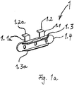
- FIG. 1a shows a perspective view of the mounting member 1 according to the invention.
- Fig. 1b is a section through the mounting member 1 or a side view of the mounting member 1 from Fig. 1 shown.
- Like elements of the invention will be denoted by like reference numerals in the following drawings to facilitate understanding of the invention.
- the mounting element 1 comprises a cantilever section 1.2, a spacer 1.1, a support section 1.3 and a mounting section 1.4.
- the Kragabites 1.2, and the spacer 1.1 can at an outer edge 11 (see Fig. 1c ) of a window frame 10 are hung or put on; They can therefore be applied to the outer edge 11 of the window frame 10.
- the mounting element 1 is applied to the outer edge 11 or hung on the outer edge 11, preferably the spacer 1.1 and the Kragabites 1.2 at least in sections contact the outer edge 11 as in Fig. 1c shown.
- the mounting element 1 in Fig. 1c is in a created position.
- Fig. 1c shows the mounting element 1 from FIGS. 1a and 1b in a created position.
- the mounting member 1 further comprises a mounting portion 1.4 which is adapted to rest in the applied position of the mounting member 1 on a surface of the window frame 10, which is bounded by the outer edge 11.
- the attachment section 1.4 is connected to at least one support section 1.3.
- the mounting element of the mounting portion 1.4 and the support portion 1.3 are designed as a unitary element.
- the mounting element 1 may comprise more than one support section 1.3, as in Fig. 1a shown a second support section 1.3a.
- the support sections 1.3 are designed so that they can be connected to a frame 50 (not shown). Preferably, the frame 50 can be brought into engagement with the support section 1.3.
- the person skilled in the corresponding intervention means are well known.
- the support sections 1.3 and / or the second support section 1.3a in Fig. 1a be designed as a spring element that can be locked in a profile and thereby carries the latched profile.
- the attachment portion 1.4 carries a fastener 1.5.
- the fastening means 1.5 is in Fig. 1b as an adhesive element, e.g. B. executed in the form of a double-sided adhesive tape.
- Alternative fastening means 1.5 are well known to those skilled in the art, for example Velcro, which provides a connection between window frame 10 and fastening element 1.4.
- Advantageous are those fasteners that require no holes on the window frame 10 and can be removed without leaving residue.
- magnetic fastening means 1.5 are conceivable. These are particularly advantageous in connection with metallic and / or magnetic window frames 10.
- a magnetic fastener 1.5 is advantageous when the mounting member 1 is made metallic. It is conceivable, for example, the use of rare earth magnets as fasteners 1.5 due to their high adhesive force.
- Attach the support section 1.3 to the window frame 10 provide.
- the fastening element 1.4 would also be fastened to the window frame 10 if the mounting element is formed from a sufficiently strong material and is in a position applied to the outer edge.
- the spacer 1.1 and the cantilever 1.2 provide the desired defined distance to the window frame 10 safe when the fastener 1 is in an applied position.
- spacer 1.1 and / or cantilever 1.2 are to be applied to the outer edge 11, as described.
- mounting element 1 support section 1.3 and mounting section 1.4 are executed in one piece.
- the spacer 1.1 and the Kragabites 1.2 need not be applied to the outer edge 11, unless the attachment means 1.5 is attached to the spacer 1.1 and / or the Kragabites 1.2.
- the mounting member 1 include a second spacer 1.1a and a second Kragabites 1.2a.
- a second support section 1.3a can be seen.
- the mounting element 1 of the invention can comprise only one pair of spacer element 1.1 and cantilever section 1.2.
- more than two pairs of spacer 1.1, 1.1 a and Kragabites 1.2, 1.2a are conceivable.
- the Kragabroughe 1.2, 1.2a and the spacer elements 1.1, 1.1a are hung or applied to an outer edge 11 of a window frame 10; They are therefore applied to the outer edge 11 of the window frame 10, as already described for the Kragabites 1.2 and the spacer 1.1.
- the mounting member 1 is by means of each pair of spacer 1.1, 1.1a, 1.1b and Kragabites 1.2, 1.2a, 1.2b at least one of the outer edges 11, 11a, 11b of the window frame 10 can be applied.
- the mounting element 1 of the present invention has only one support section 1.3, the support section 1.3 and a second support section 1.3a, as in FIG Fig. 1a and 1b or may include more support sections.
- the support sections 1.3, 1.3a are adapted to support or fix the frame 50 (not shown) of an insect protection device 60.
- the mounting member 1 results in the simultaneous, partially touching the outer edge 11 by at least one of the pairs of Kragabonce 1.2, 1.2a and spacer 1.1, 1.1a provided that the outer edge 11 defines a substantially rectangular profile of the window frame 10.
- the mounting element 1 of the invention is not limited to such substantially rectangular profiles of the window frame 10. Rather, the mounting element 1 of the invention can also be used on outer edges 11, which limit a non-rectangular profile of the window frame 10.
- a corresponding angle between the spacer element 1.1 and the cantilever section 1.2 could be adjusted so that it substantially corresponds to the non-rectangular angle of the profile of the window frame 10.
- the spacing element 1.1 and the cantilever section 1.2 from a sufficiently flexible material, such as soft plastic or rubber, so that both can follow a profile of the window frame 10 when they are applied to the outer edge 11.
- FIG. 1a shown mounting element 1 comprises three holes through which the fastening element 1.4 can optionally be fixed to the window frame 10 in an applied position by means of suitable fastening means, such as screws.
- suitable fastening means such as screws.
- the fastening means 1.5 can be chosen so strong that they are able to support the frame 50 of the insect protection device 60. Therefore, holes in the window frame 10 can be omitted, which may be useful in particular for rented apartments or buildings, if the tenant wants to attach to a window frame, the insect protection device of the invention.
- the window frames 10 shown in this description frame a rectangular window.
- the mounting element 1 is also attached to a triangular, polygonal, round or oval window frame 10 (not shown) can be applied to position a correspondingly shaped insect protection device 60.
- a round or oval window frame 10 it may be necessary for the fastening section 1.4 to follow a corresponding curvature of the window frame 10.
- a gauze-covered frame 50 as an insect protection device 60 or a roller blind already adapted to the round or oval shape of the window frame 10.
- the dimensions of the mounting element 1 are to be selected such that the support sections 1.3, 1.3a and the attachment section 1.4 come to lie on the window frame 10 when the spacer element 1.1 and the cantilever section 1.2 are applied to the outer edge 11 of the window frame 10; the mounting member 1 is thus in an applied position.
- This is advantageous because the window frame 10 is usually smoother than the adjacent brickwork. The attachment of the mounting portion 1.4 on the window frame 10 is therefore easier on the window frame 10 than on the adjacent masonry.
- window frames 10 are typically more dimensionally stable than the surrounding masonry, so that it is easier to provide an insect device 60 whose dimensions are adapted only to the window frame 10, when it is necessary to safely close the window by means of an insect protection device 60 against insects.
- the support section 1.3, 1.3a of the mounting element 1 is suitable for carrying or holding an insect protection device 60.
- a perforation line 1.7 is provided (good to see in Fig. 1 b) along which the separation can be made conveniently.
- the perforation line 1.7 is therefore preferably chosen so that when separated spacer elements 1.1, 1.1a and separated Kragabroughen 1.2, 1.2a, the mounting element. 1 no longer rests or applies on the outer edge 11.
- Fig. 2 shows a further embodiment of a fastener 1 of the invention.
- the fastener 1 in Fig. 2 is adapted to be applied to the outer edge 11 and a further outer edge 11a. Therefore, the mounting member 1 of this embodiment can be conveniently applied to a corner of the window frame 10 where the outer edge 11 and the second outer edge 11a intersect each other.
- the mounting portion 1.4 is angled in this embodiment and follows the window frame 10 around the corner, which is formed by the outer edge 11 and the second outer edge 11 a.
- the spacing element 1.1 sets a distance of the fastening section 1.4 and thus of the support section 1.3 from the outer edge 11, when the fastening element 1 is applied to the outer edge 11.
- the Kragabites 1.2 has in the drawing to the rear and is in contact with the outer edge 11 when the mounting member 1 is applied to the outer edge 11, that is, when the mounting member 1 is in an applied position.
- a second outer edge 11a which in Fig. 2 is intended to extend vertically, sets the second spacer 1.1a a distance of a second support section 1.3a to the second outer edge 11a fixed.
- a second cantilever section 1.2a and the second spacer element 1.1a can be applied to the second outer edge 11a, as already described for the first outer edge 11.
- the support section 1.3 and the second support section 1.3a are each at a defined distance from the outer edge 11 and the second outer edge 11a.
- the Carrying section 1.3 and the second support portion a defined distance from the corner of the window frame 10, which is formed by the outer edge 11 and the second outer edge 11a a.
- the support section 1.3 and the second support section 1.3a are designed as smooth surfaces.
- This embodiment of the support sections 1.3, 1.3a is particularly suitable for the interaction of Tragabscnitte 1.3, 1.3a with guide lugs 51, or other elements that are attached in the drawing from above on the mounting element 1.
- the mounting element 1 off Fig. 2 also with the support sections as in Fig. 1a to 1c be combined - instead of or in addition to the in Fig. 2 shown.
- FIG. 2 shown embodiment comprises fastening means 1.5 (not shown) which allow attachment of the mounting member 1 to the window frame, as already for the embodiments in Fig. 1a - 1c discussed.
- Fig. 3 shows a further embodiment of the mounting member 1 of the present invention.
- the mounting element 1 of Fig. 3 is particularly suitable to be applied to a corner of the window frame 10, which is formed by the outer edge 11 and a further outer edge 11 b.
- the spacer 1.1 and the Kragabonce 1.2 of the embodiment Fig. 3 are adapted to define a defined distance to the outer edge 11 and to the outer outer edge 11 a when the mounting element 1 is in a position applied to a corner of the window frame 10.
- the position of the mounting element 1 applied to a corner of the window frame 10 is determined by the fact that the mounting element 1 is applied to the outer edge 11 and to the second outer edge 11 a, which form the corner of the window frame 10.
- the mounting member 1 is sufficient a pair of spacer 1.1 and Kragabites 1.2 to make the mounting element 1 at two outer edges 11, 11a simultaneously applied.
- the pair of spacer 1.1 and cantilever 1.2 is sufficient to align the mounting member 1 at a corner of the window frame 10, which is formed from a first outer edge 11 and a second outer edge 11a of the window frame.
- Fig. 3 Correspond to the support section 1.3 and the second support section 1.3a already in Fig. 1a - 1c illustrated support section 1.3
- the fastener 1.4 and the support section 1.3 are in the depth opposite to the second fastening element 1.4a and the second support section 1.3a added.
- this offset is without limitation to the invention and rather by a in Fig. 3 different selected profile thickness of individual parts of a frame 50 of the insect device 60 justified.
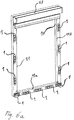
- Fig. 4 shows a window frame 10, at the upper corner of the mounting element 1 according to Fig. 2 can be seen in the position created on a corner. Further, in the lower corner of the window frame 10, the fastener 1 according to the embodiment Fig. 3 shown in the position applied at the bottom corner. Once these fasteners 1 are fixed in the position applied to the respective corner, the Kragabitese 1.2 and the spacer elements 1.1 along the perforation lines 1.7 can be separated. The fixation of the fasteners 1 in on the window frame 10 is provided as before by a fastener (not shown) 1.5.
- the present invention further contemplates an insect repellent device 60.
- the insect protection device 60 comprises at least one mounting element 1 according to the invention, and a frame 50.
- the at least one mounting element 1 can be applied to at least one outer edge 11 of the window frame 10 and fixed in an applied position.
- the frame 50 includes a head portion 58, a first side portion 52, and a second side portion 54.
- the frame 50 is engageable with at least one of the fasteners 1. That is, the frame 50 can be brought into engagement with at least one support portion 1.3 of a fastener 1. Thereby, the frame 50 is fixed relative to the window frame 10, and an opening of the window frame 10 is straddled by the frame 50.
- frame 50 of an insect protection device 60 which are formed from profiled strips, which are connected by means of corner pieces to a frame 50.
- the profile strips can be made of metal or plastic, for example aluminum or PVC.
- the dimensions of the frame 50 are to be chosen so that the frame 50 is larger than the opening of the window frame 10 on the outside of the window frame 10.
- the dimensions of the frame 50 are selected so that the profile strips of the frame 50 at least partially on the outside of the window frame 10 come to rest when the frame 50 is centered on the opening of the window frame 10.
- the Dimensions of the frame 50 are selected so that the profile strips of the frame 50 come to lie completely on the outside of the window frame 10 when the frame 50 is centered on the opening of the window frame 10.
- At least one mounting member 1 facilitates the assembly of the frame 50 at the opening of the window frame 10, provided that the mounting member 1 is applied to the outer edge 11 of the window frame 10.
- the suitable dimensions of the frame 50 can be determined from this, so that the profiles of the frame 50 come to lie completely on the outside of the window frame 10, when the frame 50 engages in the at least one mounting element 1.
- the insect protection device 60 of the invention using the mounting elements 1 results in known dimensions of the window opening a defined position of the components of the frame 50 of the insect protection device 60 when the mounting members 1 are each in an applied position; be it on only one of the outer edges 11, 11a, 11b or on two of the outer edge 11, the second outer edge 11a and the outer edge 11b, as will be briefly explained below.
- Fig. 5a shows a section of a window frame 10, in whose upper corners in each case a mounting element 1 according to the embodiment Fig. 2 can be seen in the applied position.
- One of the mounting elements 1 is applied to the outer edge 11 and the second outer edge 11a
- the other of the mounting elements 1 is applied to the outer edge 11 and a further outer edge 11b.
- a roller blind 58 can be shortened or sawn so that guide lugs 51 can be guided at the ends of the two mounting elements 1. If the guide lugs 51 on the mounting elements 1, as in Fig. 5a led to see results almost by itself a correct orientation of the roller blind 58 to the further outer edge 11b of the window opening.
- a roller blind 58 as in Fig. 5a is known in the art.
- the use of the mounting elements 1 of the invention facilitates the alignment of the roller blind 58 and thus its mounting compared to the prior art considerably.
- Fig. 5b shows a side view of the arrangement Fig. 5a , It can be seen that the roller blind 58 carries a fastening means 57, which allows for snapping the guide lugs 51 on the mounting elements 1, a convenient attachment of the blinds 58 on the window frame 10.
- the attachment means 57 may preferably be designed as an adhesive.
- magnetic fastening means are conceivable, such as rare earth magnets due to their high adhesive force.
- a hook and loop fastener 57 is conceivable as a fastening means.
- Other fasteners 57 are known in the art. In the prior art possibly required holes for fixing the blinds in the window frame 10 may be omitted for the inventive insect protection device 60.
- the shade 58 can be precisely positioned on or on the window frame 10 when aligned with the applied mounting elements 1.
- an end bar 59 of the blind 58 is shown, as is known in the art.
- the end bar 58 limits the shade.
- the end bar 59 runs between the first side part 52 and the second side part 54 (best seen in FIG Fig. 6a and 7 ) of the frame 50 of the insect repellent device 60.
- Fig. 6a shows a window frame 10 to which the head part 58 is already attached.
- a plurality of mounting members 1 are shown on the window frame 10 in an applied position.
- mounting members 1 are shown on the window frame 10 in the position applied to the outer edge 11 and the second outer edge 11a - in the Fig. 6a in the lower left corner of the window frame 10.
- Fig. 6a a mounting member 1 in the position applied to the second outer edge 11a and the further outer edge 11b - to see in the figure in the lower right corner of the window frame 10.
- Each of the mounting elements 1 shown has a defined distance to the or the outer edges 11, 11 a 11 b at or on which the respective mounting element 1 is applied.
- Fig. 6b shows how to mount the insect protection device 60 on the window frame 10, the first side part 52 is attached to the window frame 10.
- the first side part 52 comes in Engage with the fasteners 1, which are applied to the outer edge 11 and are fixed in each case in applied positions.
- the support elements 1.3 of these mounting elements 1 come into engagement with the first side part 52 and carry the first side part 52 and thus also the frame 50 of the insect protection device 60th
- the in the lower corner of the window frame 10 in Fig. 6b Mounting member 1 is additionally applied to the second outer edge 11 a, as in connection with Fig. 3 explained.
- the first side part 52 can engage or snap into the mounted on the outer edge 11 mounting elements 1. Jamming of the side part 52 or a press fit of the side part 52 on the support members 1.3 would also be conceivable.
- Such locking fasteners of support sections 1.3 and profile strips of the first side member 52 are known in the art. With proper coordination of the support sections 1.3, 1.3a, 1.3b on the profile and material of the side part 52, the first side part 52 can be anchored by hand with the mounting elements 1 in the aligned positions.
- the second side element 54 of the frame 50 can engage in mounting elements 1.
- the mounting members 1 that can engage with the second side member 54 are fixed in positions applied to the other outer edge 11b.
- the mounting element 1 shown in the right corner of the window frame 10 is additionally applied to the second outer edge 11 b of the window frame 10.
- the second side part 54 can be anchored by hand with the mounting elements 1 in the aligned positions.
- Fig. 6c shows how an optional termination element 56 can be attached to the window frame 10, that is attachable thereto.
- the closing element 56 comes into engagement with fastening elements 1 which are attached and fixed on the second outer edge 11a.
- the blind 53 can also be closed by the end bar 59 to the window frame, so that the closing element 56 can be omitted to effectively close the opening of the window frame 10 against insects.
- the mounting elements 1 comprises and has been attached by means of these mounting elements 1 on the window frame 10.
- Fig. 4-7 the blind 53 had been drawn as running from top to bottom.
- the roller blind could also run from bottom to top, from right to left or from left to right.
- insect protection devices 60 whose roller blind 53 does not extend from top to bottom, the present invention can be used.
Landscapes
- Engineering & Computer Science (AREA)
- Structural Engineering (AREA)
- Life Sciences & Earth Sciences (AREA)
- Insects & Arthropods (AREA)
- Pest Control & Pesticides (AREA)
- Architecture (AREA)
- Civil Engineering (AREA)
- Wing Frames And Configurations (AREA)
- Specific Sealing Or Ventilating Devices For Doors And Windows (AREA)
Priority Applications (1)
| Application Number | Priority Date | Filing Date | Title |
|---|---|---|---|
| EP12157493.3A EP2634356B1 (fr) | 2012-02-29 | 2012-02-29 | Dispositif de protection contre les insectes et élément de montage correspondant |
Applications Claiming Priority (1)
| Application Number | Priority Date | Filing Date | Title |
|---|---|---|---|
| EP12157493.3A EP2634356B1 (fr) | 2012-02-29 | 2012-02-29 | Dispositif de protection contre les insectes et élément de montage correspondant |
Publications (2)
| Publication Number | Publication Date |
|---|---|
| EP2634356A1 true EP2634356A1 (fr) | 2013-09-04 |
| EP2634356B1 EP2634356B1 (fr) | 2016-09-14 |
Family
ID=45841185
Family Applications (1)
| Application Number | Title | Priority Date | Filing Date |
|---|---|---|---|
| EP12157493.3A Not-in-force EP2634356B1 (fr) | 2012-02-29 | 2012-02-29 | Dispositif de protection contre les insectes et élément de montage correspondant |
Country Status (1)
| Country | Link |
|---|---|
| EP (1) | EP2634356B1 (fr) |
Cited By (3)
| Publication number | Priority date | Publication date | Assignee | Title |
|---|---|---|---|---|
| CN103912212A (zh) * | 2014-04-04 | 2014-07-09 | 浙江瑞明节能科技股份有限公司 | 一种新型的平开门纱窗 |
| WO2015124804A2 (fr) | 2014-06-27 | 2015-08-27 | Grasso Alessandro | Moustiquaire magnétique universelle |
| EP4001583A1 (fr) * | 2020-11-18 | 2022-05-25 | Büdenbender, Arnd | Élément de maintien et dispositif de protection doté d'un tel élément de maintien |
Citations (4)
| Publication number | Priority date | Publication date | Assignee | Title |
|---|---|---|---|---|
| US2114746A (en) * | 1935-02-23 | 1938-04-19 | United Carr Fastener Corp | Fastening device |
| DE102005000692B3 (de) * | 2005-01-04 | 2006-06-01 | Proflytec Insektenschutzsystemtechnik Gmbh | Vorsatzfenster |
| DE102006037795A1 (de) * | 2006-08-04 | 2008-02-07 | Neher Systeme Gmbh & Co. Kg | Insektenschutzvorrichtung |
| DE102008030726A1 (de) * | 2008-07-01 | 2010-01-07 | Lämmermann, Gerd | Insektenschutzvorrichtung zum Einhängen in einen Blendrahmen einer Tür oder eines Fensters |
-
2012
- 2012-02-29 EP EP12157493.3A patent/EP2634356B1/fr not_active Not-in-force
Patent Citations (4)
| Publication number | Priority date | Publication date | Assignee | Title |
|---|---|---|---|---|
| US2114746A (en) * | 1935-02-23 | 1938-04-19 | United Carr Fastener Corp | Fastening device |
| DE102005000692B3 (de) * | 2005-01-04 | 2006-06-01 | Proflytec Insektenschutzsystemtechnik Gmbh | Vorsatzfenster |
| DE102006037795A1 (de) * | 2006-08-04 | 2008-02-07 | Neher Systeme Gmbh & Co. Kg | Insektenschutzvorrichtung |
| DE102008030726A1 (de) * | 2008-07-01 | 2010-01-07 | Lämmermann, Gerd | Insektenschutzvorrichtung zum Einhängen in einen Blendrahmen einer Tür oder eines Fensters |
Cited By (4)
| Publication number | Priority date | Publication date | Assignee | Title |
|---|---|---|---|---|
| CN103912212A (zh) * | 2014-04-04 | 2014-07-09 | 浙江瑞明节能科技股份有限公司 | 一种新型的平开门纱窗 |
| WO2015124804A2 (fr) | 2014-06-27 | 2015-08-27 | Grasso Alessandro | Moustiquaire magnétique universelle |
| WO2015124804A3 (fr) * | 2014-06-27 | 2015-11-26 | Grasso Alessandro | Moustiquaire magnétique universelle |
| EP4001583A1 (fr) * | 2020-11-18 | 2022-05-25 | Büdenbender, Arnd | Élément de maintien et dispositif de protection doté d'un tel élément de maintien |
Also Published As
| Publication number | Publication date |
|---|---|
| EP2634356B1 (fr) | 2016-09-14 |
Similar Documents
| Publication | Publication Date | Title |
|---|---|---|
| EP3344843B1 (fr) | Dispositif de protection de doigt pour une porte battante | |
| DE202008016094U1 (de) | Vorrichtung für den Einklemmschutz an Drehflügeltüren | |
| DE202011110825U1 (de) | Befestigungsvorrichtung für Sonnenschutzeinrichtungen | |
| EP2634356B1 (fr) | Dispositif de protection contre les insectes et élément de montage correspondant | |
| DE202013100640U1 (de) | Seilspannvorrichtung und Spannset für ein Spannseil zum Tragen eines Vorhangelements | |
| DE102014119021A1 (de) | Anordnung zum Befestigen eines Pfostens aus Kunststoff an einer Rahmenleiste eines Fensters oder einer Türe mittels eines Pfostenverbinders | |
| DE3048333C2 (de) | Halterungsvorrichtung für ein Springrollo | |
| EP2634357B9 (fr) | Dispositif de protection contre les insectes et aide au positionnement pour son positionnement | |
| DE102013003012A1 (de) | Flächenvorhangsystem | |
| DE202012101001U1 (de) | Insektenschutzvorrichtung und Montageelement dafür | |
| EP1382790A2 (fr) | Dispositif de protection solaire | |
| EP3428375B1 (fr) | Dispositif de protection pour doigt | |
| DE202017100066U1 (de) | Transparente Befestigungsvorrichtung für Licht- und/oder Blickschutzanordnungen | |
| DE102005008645A1 (de) | Eckverbinder zum Verbinden zweier Profilleisten | |
| DE202012101003U1 (de) | Insektenschutzvorrichtung und Positionierhilfe dafür | |
| DE102011112866B3 (de) | Insektenschutzvorrichtung | |
| EP2592212A1 (fr) | Angle de montage pour un accessoire devant être installé sur des fenêtres ou des portes | |
| DE102014001887A1 (de) | Gebäudeöffnungsverschattungsvorrichtung und Führungsschiene dafür | |
| EP3361038B1 (fr) | Dispositif destiné à la fixation d'un dispositif de fonction sur une fenêtre ou sur une porte | |
| DE202014007079U1 (de) | Insektennetz | |
| DE202010000749U1 (de) | Klemmhalterung mit abgewinkelter Montagefläche | |
| DE29613763U1 (de) | Stoffartige Insekten- und/oder Lichtschutzeinrichtung | |
| DE102004001054A1 (de) | Verfahren und Vorrichtung zum Ausbreiten einer Bahn | |
| DE202017103279U1 (de) | Schutzvorrichtung, insbesondere als Dachfenster-Insektenschutz | |
| DE7414512U (de) | Vorrichtung zur Festlegung von Türzargen und dergleichen |
Legal Events
| Date | Code | Title | Description |
|---|---|---|---|
| PUAI | Public reference made under article 153(3) epc to a published international application that has entered the european phase |
Free format text: ORIGINAL CODE: 0009012 |
|
| 17P | Request for examination filed |
Effective date: 20130206 |
|
| AK | Designated contracting states |
Kind code of ref document: A1 Designated state(s): AL AT BE BG CH CY CZ DE DK EE ES FI FR GB GR HR HU IE IS IT LI LT LU LV MC MK MT NL NO PL PT RO RS SE SI SK SM TR |
|
| AX | Request for extension of the european patent |
Extension state: BA ME |
|
| RAP1 | Party data changed (applicant data changed or rights of an application transferred) |
Owner name: SCHOENBERGER GERMANY ENTERPRISES GMBH & CO. KG |
|
| GRAP | Despatch of communication of intention to grant a patent |
Free format text: ORIGINAL CODE: EPIDOSNIGR1 |
|
| RIC1 | Information provided on ipc code assigned before grant |
Ipc: E06B 9/52 20060101AFI20160229BHEP |
|
| INTG | Intention to grant announced |
Effective date: 20160401 |
|
| GRAP | Despatch of communication of intention to grant a patent |
Free format text: ORIGINAL CODE: EPIDOSNIGR1 |
|
| INTG | Intention to grant announced |
Effective date: 20160701 |
|
| GRAS | Grant fee paid |
Free format text: ORIGINAL CODE: EPIDOSNIGR3 |
|
| GRAA | (expected) grant |
Free format text: ORIGINAL CODE: 0009210 |
|
| AK | Designated contracting states |
Kind code of ref document: B1 Designated state(s): AL AT BE BG CH CY CZ DE DK EE ES FI FR GB GR HR HU IE IS IT LI LT LU LV MC MK MT NL NO PL PT RO RS SE SI SK SM TR |
|
| REG | Reference to a national code |
Ref country code: GB Ref legal event code: FG4D Free format text: NOT ENGLISH |
|
| REG | Reference to a national code |
Ref country code: CH Ref legal event code: EP |
|
| REG | Reference to a national code |
Ref country code: IE Ref legal event code: FG4D Free format text: LANGUAGE OF EP DOCUMENT: GERMAN |
|
| REG | Reference to a national code |
Ref country code: AT Ref legal event code: REF Ref document number: 829221 Country of ref document: AT Kind code of ref document: T Effective date: 20161015 |
|
| REG | Reference to a national code |
Ref country code: DE Ref legal event code: R096 Ref document number: 502012008187 Country of ref document: DE |
|
| REG | Reference to a national code |
Ref country code: LT Ref legal event code: MG4D |
|
| REG | Reference to a national code |
Ref country code: NL Ref legal event code: MP Effective date: 20160914 |
|
| PG25 | Lapsed in a contracting state [announced via postgrant information from national office to epo] |
Ref country code: HR Free format text: LAPSE BECAUSE OF FAILURE TO SUBMIT A TRANSLATION OF THE DESCRIPTION OR TO PAY THE FEE WITHIN THE PRESCRIBED TIME-LIMIT Effective date: 20160914 Ref country code: LT Free format text: LAPSE BECAUSE OF FAILURE TO SUBMIT A TRANSLATION OF THE DESCRIPTION OR TO PAY THE FEE WITHIN THE PRESCRIBED TIME-LIMIT Effective date: 20160914 Ref country code: NO Free format text: LAPSE BECAUSE OF FAILURE TO SUBMIT A TRANSLATION OF THE DESCRIPTION OR TO PAY THE FEE WITHIN THE PRESCRIBED TIME-LIMIT Effective date: 20161214 Ref country code: FI Free format text: LAPSE BECAUSE OF FAILURE TO SUBMIT A TRANSLATION OF THE DESCRIPTION OR TO PAY THE FEE WITHIN THE PRESCRIBED TIME-LIMIT Effective date: 20160914 Ref country code: RS Free format text: LAPSE BECAUSE OF FAILURE TO SUBMIT A TRANSLATION OF THE DESCRIPTION OR TO PAY THE FEE WITHIN THE PRESCRIBED TIME-LIMIT Effective date: 20160914 |
|
| PG25 | Lapsed in a contracting state [announced via postgrant information from national office to epo] |
Ref country code: SE Free format text: LAPSE BECAUSE OF FAILURE TO SUBMIT A TRANSLATION OF THE DESCRIPTION OR TO PAY THE FEE WITHIN THE PRESCRIBED TIME-LIMIT Effective date: 20160914 Ref country code: NL Free format text: LAPSE BECAUSE OF FAILURE TO SUBMIT A TRANSLATION OF THE DESCRIPTION OR TO PAY THE FEE WITHIN THE PRESCRIBED TIME-LIMIT Effective date: 20160914 Ref country code: GR Free format text: LAPSE BECAUSE OF FAILURE TO SUBMIT A TRANSLATION OF THE DESCRIPTION OR TO PAY THE FEE WITHIN THE PRESCRIBED TIME-LIMIT Effective date: 20161215 Ref country code: LV Free format text: LAPSE BECAUSE OF FAILURE TO SUBMIT A TRANSLATION OF THE DESCRIPTION OR TO PAY THE FEE WITHIN THE PRESCRIBED TIME-LIMIT Effective date: 20160914 |
|
| PG25 | Lapsed in a contracting state [announced via postgrant information from national office to epo] |
Ref country code: EE Free format text: LAPSE BECAUSE OF FAILURE TO SUBMIT A TRANSLATION OF THE DESCRIPTION OR TO PAY THE FEE WITHIN THE PRESCRIBED TIME-LIMIT Effective date: 20160914 Ref country code: RO Free format text: LAPSE BECAUSE OF FAILURE TO SUBMIT A TRANSLATION OF THE DESCRIPTION OR TO PAY THE FEE WITHIN THE PRESCRIBED TIME-LIMIT Effective date: 20160914 |
|
| PG25 | Lapsed in a contracting state [announced via postgrant information from national office to epo] |
Ref country code: CZ Free format text: LAPSE BECAUSE OF FAILURE TO SUBMIT A TRANSLATION OF THE DESCRIPTION OR TO PAY THE FEE WITHIN THE PRESCRIBED TIME-LIMIT Effective date: 20160914 Ref country code: BE Free format text: LAPSE BECAUSE OF NON-PAYMENT OF DUE FEES Effective date: 20170228 Ref country code: PT Free format text: LAPSE BECAUSE OF FAILURE TO SUBMIT A TRANSLATION OF THE DESCRIPTION OR TO PAY THE FEE WITHIN THE PRESCRIBED TIME-LIMIT Effective date: 20170116 Ref country code: BG Free format text: LAPSE BECAUSE OF FAILURE TO SUBMIT A TRANSLATION OF THE DESCRIPTION OR TO PAY THE FEE WITHIN THE PRESCRIBED TIME-LIMIT Effective date: 20161214 Ref country code: IS Free format text: LAPSE BECAUSE OF FAILURE TO SUBMIT A TRANSLATION OF THE DESCRIPTION OR TO PAY THE FEE WITHIN THE PRESCRIBED TIME-LIMIT Effective date: 20170114 Ref country code: PL Free format text: LAPSE BECAUSE OF FAILURE TO SUBMIT A TRANSLATION OF THE DESCRIPTION OR TO PAY THE FEE WITHIN THE PRESCRIBED TIME-LIMIT Effective date: 20160914 Ref country code: SM Free format text: LAPSE BECAUSE OF FAILURE TO SUBMIT A TRANSLATION OF THE DESCRIPTION OR TO PAY THE FEE WITHIN THE PRESCRIBED TIME-LIMIT Effective date: 20160914 Ref country code: SK Free format text: LAPSE BECAUSE OF FAILURE TO SUBMIT A TRANSLATION OF THE DESCRIPTION OR TO PAY THE FEE WITHIN THE PRESCRIBED TIME-LIMIT Effective date: 20160914 Ref country code: ES Free format text: LAPSE BECAUSE OF FAILURE TO SUBMIT A TRANSLATION OF THE DESCRIPTION OR TO PAY THE FEE WITHIN THE PRESCRIBED TIME-LIMIT Effective date: 20160914 |
|
| REG | Reference to a national code |
Ref country code: DE Ref legal event code: R097 Ref document number: 502012008187 Country of ref document: DE |
|
| PG25 | Lapsed in a contracting state [announced via postgrant information from national office to epo] |
Ref country code: IT Free format text: LAPSE BECAUSE OF FAILURE TO SUBMIT A TRANSLATION OF THE DESCRIPTION OR TO PAY THE FEE WITHIN THE PRESCRIBED TIME-LIMIT Effective date: 20160914 |
|
| PLBE | No opposition filed within time limit |
Free format text: ORIGINAL CODE: 0009261 |
|
| STAA | Information on the status of an ep patent application or granted ep patent |
Free format text: STATUS: NO OPPOSITION FILED WITHIN TIME LIMIT |
|
| PG25 | Lapsed in a contracting state [announced via postgrant information from national office to epo] |
Ref country code: DK Free format text: LAPSE BECAUSE OF FAILURE TO SUBMIT A TRANSLATION OF THE DESCRIPTION OR TO PAY THE FEE WITHIN THE PRESCRIBED TIME-LIMIT Effective date: 20160914 |
|
| 26N | No opposition filed |
Effective date: 20170615 |
|
| REG | Reference to a national code |
Ref country code: DE Ref legal event code: R119 Ref document number: 502012008187 Country of ref document: DE |
|
| PG25 | Lapsed in a contracting state [announced via postgrant information from national office to epo] |
Ref country code: MC Free format text: LAPSE BECAUSE OF FAILURE TO SUBMIT A TRANSLATION OF THE DESCRIPTION OR TO PAY THE FEE WITHIN THE PRESCRIBED TIME-LIMIT Effective date: 20160914 |
|
| REG | Reference to a national code |
Ref country code: CH Ref legal event code: PL |
|
| GBPC | Gb: european patent ceased through non-payment of renewal fee |
Effective date: 20170228 |
|
| PG25 | Lapsed in a contracting state [announced via postgrant information from national office to epo] |
Ref country code: LI Free format text: LAPSE BECAUSE OF NON-PAYMENT OF DUE FEES Effective date: 20170228 Ref country code: CH Free format text: LAPSE BECAUSE OF NON-PAYMENT OF DUE FEES Effective date: 20170228 |
|
| REG | Reference to a national code |
Ref country code: IE Ref legal event code: MM4A |
|
| PG25 | Lapsed in a contracting state [announced via postgrant information from national office to epo] |
Ref country code: SI Free format text: LAPSE BECAUSE OF FAILURE TO SUBMIT A TRANSLATION OF THE DESCRIPTION OR TO PAY THE FEE WITHIN THE PRESCRIBED TIME-LIMIT Effective date: 20160914 |
|
| REG | Reference to a national code |
Ref country code: FR Ref legal event code: ST Effective date: 20171031 |
|
| PG25 | Lapsed in a contracting state [announced via postgrant information from national office to epo] |
Ref country code: LU Free format text: LAPSE BECAUSE OF NON-PAYMENT OF DUE FEES Effective date: 20170228 |
|
| PG25 | Lapsed in a contracting state [announced via postgrant information from national office to epo] |
Ref country code: DE Free format text: LAPSE BECAUSE OF NON-PAYMENT OF DUE FEES Effective date: 20170901 Ref country code: FR Free format text: LAPSE BECAUSE OF NON-PAYMENT OF DUE FEES Effective date: 20170228 |
|
| REG | Reference to a national code |
Ref country code: BE Ref legal event code: MM Effective date: 20170228 |
|
| PG25 | Lapsed in a contracting state [announced via postgrant information from national office to epo] |
Ref country code: GB Free format text: LAPSE BECAUSE OF NON-PAYMENT OF DUE FEES Effective date: 20170228 Ref country code: IE Free format text: LAPSE BECAUSE OF NON-PAYMENT OF DUE FEES Effective date: 20170228 |
|
| REG | Reference to a national code |
Ref country code: AT Ref legal event code: MM01 Ref document number: 829221 Country of ref document: AT Kind code of ref document: T Effective date: 20170228 |
|
| PG25 | Lapsed in a contracting state [announced via postgrant information from national office to epo] |
Ref country code: AT Free format text: LAPSE BECAUSE OF NON-PAYMENT OF DUE FEES Effective date: 20170228 |
|
| PG25 | Lapsed in a contracting state [announced via postgrant information from national office to epo] |
Ref country code: MT Free format text: LAPSE BECAUSE OF FAILURE TO SUBMIT A TRANSLATION OF THE DESCRIPTION OR TO PAY THE FEE WITHIN THE PRESCRIBED TIME-LIMIT Effective date: 20160914 |
|
| PG25 | Lapsed in a contracting state [announced via postgrant information from national office to epo] |
Ref country code: AL Free format text: LAPSE BECAUSE OF FAILURE TO SUBMIT A TRANSLATION OF THE DESCRIPTION OR TO PAY THE FEE WITHIN THE PRESCRIBED TIME-LIMIT Effective date: 20160914 |
|
| PG25 | Lapsed in a contracting state [announced via postgrant information from national office to epo] |
Ref country code: HU Free format text: LAPSE BECAUSE OF FAILURE TO SUBMIT A TRANSLATION OF THE DESCRIPTION OR TO PAY THE FEE WITHIN THE PRESCRIBED TIME-LIMIT; INVALID AB INITIO Effective date: 20120229 |
|
| PG25 | Lapsed in a contracting state [announced via postgrant information from national office to epo] |
Ref country code: CY Free format text: LAPSE BECAUSE OF NON-PAYMENT OF DUE FEES Effective date: 20160914 |
|
| PG25 | Lapsed in a contracting state [announced via postgrant information from national office to epo] |
Ref country code: MK Free format text: LAPSE BECAUSE OF FAILURE TO SUBMIT A TRANSLATION OF THE DESCRIPTION OR TO PAY THE FEE WITHIN THE PRESCRIBED TIME-LIMIT Effective date: 20160914 |
|
| PG25 | Lapsed in a contracting state [announced via postgrant information from national office to epo] |
Ref country code: TR Free format text: LAPSE BECAUSE OF FAILURE TO SUBMIT A TRANSLATION OF THE DESCRIPTION OR TO PAY THE FEE WITHIN THE PRESCRIBED TIME-LIMIT Effective date: 20160914 |