EP2636492A2 - Kalibrierverfahren und Kalibriersystem für Roboter - Google Patents
Kalibrierverfahren und Kalibriersystem für Roboter Download PDFInfo
- Publication number
- EP2636492A2 EP2636492A2 EP20130157734 EP13157734A EP2636492A2 EP 2636492 A2 EP2636492 A2 EP 2636492A2 EP 20130157734 EP20130157734 EP 20130157734 EP 13157734 A EP13157734 A EP 13157734A EP 2636492 A2 EP2636492 A2 EP 2636492A2
- Authority
- EP
- European Patent Office
- Prior art keywords
- robot
- manipulators
- links
- installation point
- coordinates
- Prior art date
- Legal status (The legal status is an assumption and is not a legal conclusion. Google has not performed a legal analysis and makes no representation as to the accuracy of the status listed.)
- Withdrawn
Links
Images


Classifications
-
- B—PERFORMING OPERATIONS; TRANSPORTING
- B25—HAND TOOLS; PORTABLE POWER-DRIVEN TOOLS; MANIPULATORS
- B25J—MANIPULATORS; CHAMBERS PROVIDED WITH MANIPULATION DEVICES
- B25J9/00—Program-controlled manipulators
- B25J9/16—Program controls
- B25J9/1674—Program controls characterised by safety, monitoring, diagnostic
-
- B—PERFORMING OPERATIONS; TRANSPORTING
- B25—HAND TOOLS; PORTABLE POWER-DRIVEN TOOLS; MANIPULATORS
- B25J—MANIPULATORS; CHAMBERS PROVIDED WITH MANIPULATION DEVICES
- B25J9/00—Program-controlled manipulators
- B25J9/16—Program controls
- B25J9/1679—Program controls characterised by the tasks executed
- B25J9/1682—Dual arm manipulator; Coordination of several manipulators
-
- B—PERFORMING OPERATIONS; TRANSPORTING
- B25—HAND TOOLS; PORTABLE POWER-DRIVEN TOOLS; MANIPULATORS
- B25J—MANIPULATORS; CHAMBERS PROVIDED WITH MANIPULATION DEVICES
- B25J9/00—Program-controlled manipulators
- B25J9/16—Program controls
- B25J9/1679—Program controls characterised by the tasks executed
- B25J9/1692—Calibration of manipulator
-
- G—PHYSICS
- G05—CONTROLLING; REGULATING
- G05B—CONTROL OR REGULATING SYSTEMS IN GENERAL; FUNCTIONAL ELEMENTS OF SUCH SYSTEMS; MONITORING OR TESTING ARRANGEMENTS FOR SUCH SYSTEMS OR ELEMENTS
- G05B2219/00—Program-control systems
- G05B2219/30—Nc systems
- G05B2219/39—Robotics, robotics to robotics hand
- G05B2219/39048—Closed loop kinematic self calibration, grip part of robot with hand
-
- G—PHYSICS
- G05—CONTROLLING; REGULATING
- G05B—CONTROL OR REGULATING SYSTEMS IN GENERAL; FUNCTIONAL ELEMENTS OF SUCH SYSTEMS; MONITORING OR TESTING ARRANGEMENTS FOR SUCH SYSTEMS OR ELEMENTS
- G05B2219/00—Program-control systems
- G05B2219/30—Nc systems
- G05B2219/39—Robotics, robotics to robotics hand
- G05B2219/39049—Calibration cooperating manipulators, closed kinematic chain by bolting
-
- G—PHYSICS
- G05—CONTROLLING; REGULATING
- G05B—CONTROL OR REGULATING SYSTEMS IN GENERAL; FUNCTIONAL ELEMENTS OF SUCH SYSTEMS; MONITORING OR TESTING ARRANGEMENTS FOR SUCH SYSTEMS OR ELEMENTS
- G05B2219/00—Program-control systems
- G05B2219/30—Nc systems
- G05B2219/39—Robotics, robotics to robotics hand
- G05B2219/39051—Calibration cooperating manipulators, closed kinematic chain by alignment
-
- Y—GENERAL TAGGING OF NEW TECHNOLOGICAL DEVELOPMENTS; GENERAL TAGGING OF CROSS-SECTIONAL TECHNOLOGIES SPANNING OVER SEVERAL SECTIONS OF THE IPC; TECHNICAL SUBJECTS COVERED BY FORMER USPC CROSS-REFERENCE ART COLLECTIONS [XRACs] AND DIGESTS
- Y10—TECHNICAL SUBJECTS COVERED BY FORMER USPC
- Y10S—TECHNICAL SUBJECTS COVERED BY FORMER USPC CROSS-REFERENCE ART COLLECTIONS [XRACs] AND DIGESTS
- Y10S901/00—Robots
- Y10S901/02—Arm motion controller
Definitions
- the invention relates to a calibration method and calibration system for a robot.
- a calibration method for mechanism parameters, or the like, of a robot is known as a method described in Japanese Patent Application Publication No. 8-27241 ( JP 8-27241 A ), Japanese Patent Application Publication No. 2001-50741 ( JP 2001-50741 A ), or the like.
- JP 8-27241 A a robot is calibrated by a method of collectively calibrating a hand camera and the robot at the same time.
- JP 2001-50741 A the distal end of a three-dimensional measuring device is coupled to the distal end of an arm of a robot, the position and attitude of the distal end portion of the arm of the robot are measured, and a plurality of teach points are measured while changing the position and attitude of the robot.
- mechanism parameters also called robot constants
- Japanese Patent Publication No. 4-45842 describes a method of changing the attitude of a robot distal end in a state where the robot distal end is engaged with a displacement detector and then performing calibration on the basis of data of joint angles of joints and data of the displacement detector.
- JP 8-27241 A to Japanese Patent Publication No. 4-45842 require a hand camera, a three-dimensional measuring device or a displacement detector, so cost increases.
- the invention provides a calibration method and calibration system for a robot, which are able to perform calibration without using a device, such as a three-dimensional measuring device, a displacement detector and a hand camera, by changing attitudes of a pair of manipulators while coupling distal ends of the pair of manipulators to each other.
- a device such as a three-dimensional measuring device, a displacement detector and a hand camera
- a first aspect of the invention provides a calibration method for a robot.
- the calibration method includes: coupling distal ends of a pair of manipulators to each other; setting one of the manipulators as a master robot; setting the other one of the manipulators as a slave robot; causing the master robot and the slave robot to take a plurality of attitudes by outputting commands from a control device to actuators that drive links of the master robot in a state where the master robot and the slave robot are coupled to each other; acquiring coordinates of joints between the links at the time of each attitude change on the basis of position detection signals of position detectors respectively provided for the actuators that drive the links of the master robot and links of the slave robot at the time of each attitude change; calculating a position and attitude of an installation point of the slave robot at the time of each attitude change with reference to an installation point of the master robot on the basis of the coordinates of the joints, which are acquired at the time of the corresponding one of the attitude changes, in a forward kinematics manner; calculating deviations for each attitude change between actual
- the calibration method for a robot which is able to perform calibration without using a device, such as a three-dimensional measuring device, a displacement detector and a hand camera.
- a second aspect of the invention provides a calibration system for a robot.
- the calibration system includes: a pair of manipulators, each of which includes a plurality of links, actuators that are respectively provided for joints of the links and that drive the links and position detectors that are respectively provided for the actuators, that respectively detect positions of joint axes of the links and that output position detection signals; a control unit that sets one of the manipulators as a master robot, that sets the other one of the manipulators as a slave robot and that causes the master robot and the slave robot to take a plurality of attitudes by outputting commands to the actuators of the master robot in a state where distal ends of the pair of manipulators are coupled to each other; a computing unit that acquires coordinates of the joints between the links at the time of each attitude change of an installation point of the slave robot with respect to an installation point of the master robot on the basis of the position detection signals, and that calculates a position and attitude of the installation point of the slave robot at the time of the corresponding one of the attitude changes on the basis of the coordinate
- the calibration system for a robot which is able to perform calibration without using a device, such as a three-dimensional measuring device, a displacement detector and a hand camera.
- FIG. 1 to FIG. 5 a pair of manipulators 10A and 10B according to the present embodiment will be described.
- the manipulators 10A and 10B are placed within a range in which it is possible to couple both distal ends of the manipulators 10A and 10B to each other.
- both manipulators 10A and 10B have the same components, so the manipulator 10A will be described.
- Like reference numerals to those of the components of the manipulator 10A denote the components of the manipulator 10B, and the description thereof is omitted.
- the manipulator 10A is formed by serially coupling eight links 11 to 18 by seven joints 21 to 27.
- first link 11 is fixed to a floor surface FL, and the other end of the first link 11 is connected to one side of the first joint 21.
- One end of the second link 12 is connected to the other side of the first joint 21, and one side of the second joint 22 is connected to the other end of the second link 12.
- the third link 13, the fourth link 14, the fifth link 15, the sixth link 16, the seventh link 17 and the eighth link 18 are respectively coupled sequentially via the third joint 23, the fourth joint 24, the fifth joint 25, the sixth joint 26 and the seventh joint 27.
- the other side of the first joint 21 is rotatable about an axis extending vertically in FIG. 1 with respect to the one side as indicated by an arrow 31.
- the second link 12 is turnable in a direction indicated by the arrow 31 about the rotation axis (J1 axis) of the first joint 21 with respect to the adjacent first link 11.
- the other side of the second joint 22 is rotatable about an axis (J2 axis) extending in a direction perpendicular to the sheet in FIG. 1 with respect to the one side as indicated by an arrow 32.
- the third link 13 is rotatable in a direction indicated by the arrow 32 about the rotation axis of the second joint 22 with respect to the adjacent second link 12.
- the third joint 23, the fourth joint 24, the fifth joint 25, the sixth joint 26 and the seventh joint 27 each are rotatable, and the fourth link 14, the fifth link 15, the sixth link 16, the seventh link 17 and the eighth link 18 are also respectively turnable in directions indicated by arrows 33 to 37 about the rotation axes (J3 axis to J7 axis) of the joints 23 to 27.
- the pairs of links 11 to 18 that are coupled via the corresponding joints 21 to 27 are termed mutually adjacent pairs of links 11 to 18.
- the J1 axis to the J7 axis correspond to joint axes.
- FIG. 2 shows the manipulator 10A in simplified skeletal view as compared with FIG. 1 .
- a first servomotor 41 is installed in the first joint 21.
- the first servomotor 41 turns the second link 12 with respect to the first link 11.
- a second servomotor 42 is installed in the second joint 22.
- the second servomotor 42 turns the third link 13 with respect to the second link 12.
- servomotors 43 to 47 are respectively installed in the third joint 23, the fourth joint 24, the fifth joint 25, the sixth joint 26 and the seventh joint 27.
- the servomotors 43 to 47 respectively turn the corresponding links 14 to 18.
- the motors are provided in the corresponding joints; however, in FIG. 2 , the motors are shown separately from the joints for the sake of convenience of illustration.
- AC motors that serve as the servomotors are used as actuators; however, the actuators are not limited to them.
- a tool 49 is mounted at the distal end of the eighth link 18.
- the tool 49 together with the eighth link 18 is turnable in a direction indicated by an arrow 37 about the rotation axis (J7 axis) of the seventh joint 27 as shown in FIG. 1 .
- the tool 49 is, for example, a hand that is able to grasp a workpiece, or the like.
- the type of tool 49 does not affect the invention, so it is not limited.
- the manipulator 10A causes an accumulated rotation angle of the second link 12 to eighth link 18 to work on the tool 49 provided at the distal end portion by turning the second link 12 to the eighth link 18 by driving the first servomotor 41 to the seventh servomotor 47, so it is possible to bring the position and attitude of the distal end of the tool 49 into coincidence with a target position and a target attitude appropriate for work of the tool 49.
- controller RC that serves as a control unit and a control device that control the manipulators 10A and 10B with reference to FIG. 3 .
- the controller RC includes a computer 90, PWM generators 51 to 57 for the manipulator 10A, and a motor drive unit 50A.
- the PWM generators 51 to 57 for the manipulator 10A are electrically connected to the computer 90.
- the motor drive unit 50A includes servo amplifiers 61 to 67 that are electrically connected to the PWM generators 51 to 57 for the manipulator 10A.
- the controller RC further includes a motor drive unit 50B.
- the motor drive unit 50B, as well as the motor drive unit 50A, includes a plurality of PWM generators (not shown) for the manipulator 10B and servo amplifiers (not shown).
- the PWM generators (not shown) for the manipulator 10B are electrically connected to the computer 90.
- the servo amplifiers are electrically connected to the PWM generators (not shown).
- the servo amplifiers 61 to 67 of the motor drive unit 50A are respectively electrically connected to the first servomotor 41 to seventh servomotor 47 of the manipulator 10A.
- the servo amplifiers (not shown) of the motor drive unit 50B are respectively electrically connected to the first servomotor 41 to seventh servomotor 47 of the manipulator 10B.
- the computer 90 outputs joint position command values to the PWM generators 51 to 57 of the motor drive units 50A and 50B.
- the PWM generators 51 to 57 respectively output PWM signals to the servo amplifiers 61 to 67 on the basis of the joint position command values.
- the servo amplifiers 61 to 67 respectively turn the links 12 to 18 by actuating the servomotors 41 to 47 on the basis of outputs thereof.
- Rotary encoders 71 to 77 are respectively incorporated in the servomotors 41 to 47, and are connected to the computer 90 via an interface 80.
- the rotary encoders 71 to 77 respectively detect the rotation angles of the servomotors 41 to 47, that is, respectively detect the rotation angles of the links 12 to 18 with respect to the corresponding adjacent links 11 to 17, and transmit the detection signals of the rotation angles, that is, position detection signals, to the controller RC.
- the rotary encoders 71 to 77 correspond to position detectors.
- Each of the position detectors is not limited to the rotary encoder.
- Each of the position detectors may be a resolver or a potentiometer.
- sensors that are able to respectively directly detect the rotation angles of the links 12 to 18 may be provided at the links 12 to 18 or the first joint 21 to the seventh joint 27.
- the computer 90 includes a CPU 91, a ROM 92, a RAM 93, a nonvolatile storage unit 94, such as a hard disk, an interface 95, and the like, which are electrically connected to one another via a bus 96.
- the storage unit 94 stores various data, work programs for causing the robot to carry out various types of work, a calibration program, various parameters, and the like.
- the ROM 92 stores a system program of an overall system.
- the RAM 93 is a working memory of the CPU 91, and temporarily stores data when various processings, or the like, are executed.
- the CPU 91 corresponds to a computing unit, a deviation computing unit and an identification unit.
- An input device 82 is connected to the controller RC via the interface 95.
- the input device 82 is an operating panel that has a monitor screen, various input keys (which are not shown), and the like, and allows a worker to input various data.
- the input device 82 has a power switch of the articulated robot, and allows to input a final target position and final target attitude of the distal end of the tool 49 mounted at the distal end portion of each of the manipulators 10A and 10B, a position and attitude of the distal end of the tool 49 at an interpolation point to the computer 90 and allows an input for changing the attitude of each of the manipulators 10A and 10B through jog operation, or the like, to the computer 90.
- brake action on each servomotor may be generated through servo control over the servomotor (servo brake) and may be generated through a mechanical brake (not shown).
- the brake action that is generated by the mechanical brake on each servomotor is allowed to be subjected to on/off control by operating the input device 82 independently of brake through servo control.
- the calibration system is formed of the manipulators 10A and 10B, the controller RC and the CPU 91 of the controller RC.
- the manipulators 10A and 10B each include the first link 11 to the eighth link 18, the first servomotor 41 to the seventh servomotor 47 and the rotary encoders 71 to 77.
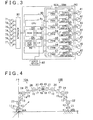
- FIG. 4 is a schematic view that illustrates a calibration method for a robot.
- FIG. 5 is a flowchart of the calibration method.
- the worker measures coordinates of an installation point WA of the manipulator 10A and coordinates of an installation point WB of the manipulator 10B in a world coordinate system with the use of a measuring jig, or the like, in advance and stores the coordinates in the storage unit 94 via the input device 82.
- the coordinates of the installation point WB of the manipulator 10B which are measured by the worker with the use of a measuring jig, or the like, in the world coordinate system in advance, are termed actual measured values in the following description.
- the world coordinate system is a three-dimensional coordinate system in the case where a certain place is set as a point of origin in an actual space.
- the world coordinate system is a three-dimensional system that uses the installation point WA between the first link 11 of the manipulator 10A and the floor surface FL as a point of origin.
- step 10 the worker couples both distal ends of the manipulators 10A and 10B, that is, both the tools 49, to each other in a state where the powers of the robots are turned off.
- a method of coupling both the tools 49 to each other is not limited.
- both the tools 49 are fastened to each other by a bolt and a nut, or the like.
- the worker turns on the powers (not shown) of the robots, uses the input device 82 to release the mechanical brake (not shown) of the manipulator 10B that serves as a slave robot.
- the manipulator 10B is set so as to be able to follow the manipulator 10A.
- the worker changes the attitude of the manipulator 10A k times through jog operation of the input device 82. Through the attitude changes, the attitude of the manipulator 10B is also changed.
- the worker operates the input device 82 to cause the CPU 91 to acquire the rotation angles of the joints during the attitude change from the rotary encoders 71 to 77, and store the rotation angles in the storage unit 94.
- Attitude change is performed such that the number k of attitude changes satisfies the inequality "6k ⁇ the total number of robot constants of both manipulators".
- "6" indicates the number of installation point coordinates X (x, y, z, a, b, c) of the installation point WB.
- x, y, z denote three-dimensional coordinate values in the world coordinate system
- a, b, c respectively denote the rotation angles (yaw angle, pitch angle, roll angle) around the three-dimensional axes.
- the installation point coordinates are intended to include three-dimensional coordinates and rotation angles around the axes of the three dimension as described above.
- the joint coordinates of each joint are the coordinate values of the joint between each link and the adjacent link, and are, for example, the coordinate values of the first joint 21, which is the joint between the first link 11 and the second link 12, in the world coordinate system.
- the CPU 91 acquires the joint coordinates of each of the first joint 21 and the second joint 22 to the seventh joint 27 in the world coordinate system on the basis of the rotation angles acquired from the rotary encoders 71 to 77 of each of the manipulators, and stores the calculated results in the storage unit 94.
- the CPU 91 calculates the robot constants.
- the robot constants are constants unique to the robot, and typically include link lengths, a position gap (offset) between any adjacent links, a twist, an offset value of the encoder of each joint axis, a warpage of each link, or the like.
- p1 to p4 are illustrated as the robot constants.
- the robot constant p1 is, for example, the link length of the first link 11, the robot constant p2 is an offset between the first joint 21 and the second joint 22, the robot constant p3 is the link length of the second link 12, and the robot constant p4 is an angle of the third link 13 from a reference plane that passes through the second joint 22.
- Robot constants before calibration are stored in the storage unit 94 as defaults in advance.
- the following definition applies to the following mathematical expressions that are calculated using the robot constants.
- the joint coordinates are denoted by ⁇ ( ⁇ 1, ⁇ 2, ..., ⁇ m).
- the robot constants are denoted by p(p1, p2, ..., pn).
- n denotes the total number of the robot constants of the two manipulators.
- the installation point coordinates X of the installation point WB of the manipulator 10B may be expressed by the mathematical expression (1).
- the CPU 91 calculates the installation point coordinates X of the installation point WB for each attitude change in a forward kinematics manner (hereinafter, these values are termed calculated values), and computes differences between the calculated values and known coordinates (actual measured values) of the installation point WB of the manipulator 10B. By so doing, the CPU 91 obtains dx, dy, dz, da, db and dc.
- the dX of the manipulator 10B may be expressed by the mathematical expression (3) and the mathematical expression (4).
- dp J T ⁇ J - 1 ⁇ J T ⁇ dX
- the CPU 91 obtains the deviation vector dp on the basis of the above-described data that are larger in number than the robot constants by applying a method of least squares. That is, the CPU 91 updates the robot constants from the obtained deviation vector of the robot constants and repeatedly makes convergence calculation until the deviation of the installation point WB becomes smaller than or equal to a preset threshold. Thus, the CPU 91 identifies the robot constants.
- the present embodiment has the following features.
- the calibration system includes the manipulators 10A and 10B, each of which includes the links 11 to 18, the servomotors 41 to 47 (actuators) provided for the joints of the links, and the rotary encoders 71 to 77 (position detectors) that respectively detect the positions of the J1 axis to J7 axis (joint axes) of the links.
- the calibration system includes the controller RC (control unit) that sets the manipulator 10A as the master robot, that sets the manipulator 10B as the slave robot and that causes the master robot and the slave robot to take a plurality of attitudes by outputting commands to the servomotors 41 to 47 (actuators) of the master robot in a state where the distal ends of the manipulators 10A and 10B are coupled to each other.
- controller RC control unit
- the calibration system includes the rotary encoders 71 to 77 (position detectors) that are respectively provided for the servomotors (actuators) that drive the links of the master robot and the links of the slave robot at the time of each attitude change.
- the CPU 91 of the calibration system functions as a computing unit that calculates the position and attitude of the installation point WB of the slave robot at the time of each attitude change on the basis of the coordinates of the joints (joint coordinates) acquired at the time of the corresponding one of the attitude changes with reference to the installation point WA of the master robot in a forward kinematics manner and a deviation computing unit that calculates deviations for each attitude change between the actual coordinates (actual measured values) of the installation point WB of the slave robot and the calculated coordinates values of the installation point of the slave robot.
- the CPU 91 of the calibration system further functions as an identification unit that identifies the robot constants of each of the manipulators 10A and 10B from the calculated deviations.
- each actuator may be a DC motor, and a stepping motor, or the like, may also be used.
- each link is rotated; instead, a cylinder or a solenoid that serves as an actuator may be used to linearly move the link with respect to the adjacent link.
- the position detector may be a linear potentiometer, a gap sensor, such as a capacitance type or an eddy current type, or the like, which detects a linear displacement of the link.
- the invention is implemented in seven-axis articulated robots; however, the invention is not limited to the seven-axis articulated robots.
- Manipulators having six or less axes or manipulators having eight or more axes may be used instead. Both the manipulators are not always limited to manipulators having the same number of axes. Manipulators having different numbers of axes may be used in combination.
- a pair of manipulators (10A, 10B) are caused to take a plurality of attitudes in a state where distal ends of the manipulators (10A, 10B) are coupled to each other, coordinates of joints between links at each attitude change are acquired on the basis of detection signals, at each attitude change, of rotary encoders provided for servomotors that drive the links of the manipulators (10A, 10B), and a position and attitude of an installation point (WB) of a slave robot with reference to an installation point (WA) of a master robot are calculated on the basis of the joint coordinates acquired at the corresponding attitude change in a forward kinematics manner.
- a deviation vector for each attitude change between actual measured values of the installation point (WB) of the slave robot and the calculated values of the installation point (WB) of the slave robot is calculated, and robot constants of both manipulators are identified from the deviation vector.
Landscapes
- Engineering & Computer Science (AREA)
- Robotics (AREA)
- Mechanical Engineering (AREA)
- Manipulator (AREA)
Applications Claiming Priority (1)
| Application Number | Priority Date | Filing Date | Title |
|---|---|---|---|
| JP2012049329A JP2013184236A (ja) | 2012-03-06 | 2012-03-06 | ロボットのキャリブレーション方法及びキャリブレーション装置 |
Publications (2)
| Publication Number | Publication Date |
|---|---|
| EP2636492A2 true EP2636492A2 (de) | 2013-09-11 |
| EP2636492A3 EP2636492A3 (de) | 2014-04-02 |
Family
ID=47877815
Family Applications (1)
| Application Number | Title | Priority Date | Filing Date |
|---|---|---|---|
| EP20130157734 Withdrawn EP2636492A3 (de) | 2012-03-06 | 2013-03-05 | Kalibrierverfahren und Kalibriersystem für Roboter |
Country Status (4)
| Country | Link |
|---|---|
| US (1) | US9014853B2 (de) |
| EP (1) | EP2636492A3 (de) |
| JP (1) | JP2013184236A (de) |
| CN (1) | CN103302657A (de) |
Cited By (1)
| Publication number | Priority date | Publication date | Assignee | Title |
|---|---|---|---|---|
| CN109196429A (zh) * | 2016-03-29 | 2019-01-11 | 康格尼博提克斯股份公司 | 用于确定操纵器的几何特性的方法、约束装置和系统 |
Families Citing this family (18)
| Publication number | Priority date | Publication date | Assignee | Title |
|---|---|---|---|---|
| US8423186B2 (en) * | 2009-06-30 | 2013-04-16 | Intuitive Surgical Operations, Inc. | Ratcheting for master alignment of a teleoperated minimally-invasive surgical instrument |
| JP5938954B2 (ja) * | 2012-03-06 | 2016-06-22 | 株式会社ジェイテクト | ロボットのキャリブレーション方法及びキャリブレーション装置 |
| WO2013175553A1 (ja) * | 2012-05-21 | 2013-11-28 | 株式会社安川電機 | ロボット |
| DE102013012448A1 (de) * | 2013-07-26 | 2015-01-29 | Kuka Laboratories Gmbh | Verfahren und Vorrichtung zum Bremsen einer Roboterachsanordnung |
| SE537534C2 (sv) * | 2013-08-27 | 2015-06-02 | Cognibotics Ab | Metod och system för bestämning av åtminstone en egenskap hos en manipulator |
| WO2015142790A1 (en) * | 2014-03-17 | 2015-09-24 | Intuitive Surgical Operations, Inc. | Restoring instrument control input position/orientation during midprocedure restart |
| CN105729441A (zh) * | 2014-12-24 | 2016-07-06 | 精工爱普生株式会社 | 机器人、机器人系统、控制装置以及控制方法 |
| GB201509341D0 (en) | 2015-05-29 | 2015-07-15 | Cambridge Medical Robotics Ltd | Characterising robot environments |
| CN104965486B (zh) * | 2015-06-17 | 2018-08-07 | 广汽本田汽车有限公司 | 一种非标机器人建模方法 |
| US9827668B2 (en) * | 2016-04-15 | 2017-11-28 | Fetch Robotics, Inc. | Robotic joint |
| CN106393174B (zh) * | 2016-10-09 | 2018-10-26 | 华中科技大学 | 一种利用球杆仪标定机器人结构参数的方法 |
| TWI639495B (zh) * | 2016-12-13 | 2018-11-01 | 日商川崎重工業股份有限公司 | 機器人之教示方法 |
| CN111683797B (zh) * | 2018-09-10 | 2024-02-27 | 深圳配天机器人技术有限公司 | 标定方法及标定装置 |
| JP7268579B2 (ja) * | 2019-11-01 | 2023-05-08 | コベルコ建機株式会社 | 油圧作業機及び遠隔操縦システム |
| KR102332314B1 (ko) | 2020-01-16 | 2021-12-01 | 한국기술교육대학교 산학협력단 | 로봇과 카메라 간 좌표값 보정 장치 및 보정 방법 |
| KR102286229B1 (ko) | 2020-02-19 | 2021-08-06 | 한국기술교육대학교 산학협력단 | 특징벡터 기반 싸움 이벤트 인식 방법 |
| DE102020104356A1 (de) * | 2020-02-19 | 2021-08-19 | Franka Emika Gmbh | Aufstellort eines Robotermanipulators |
| CN119328755B (zh) * | 2024-11-04 | 2025-10-28 | 法奥意威(苏州)机器人系统有限公司 | 机器人标定方法、装置、电子设备及存储介质 |
Citations (3)
| Publication number | Priority date | Publication date | Assignee | Title |
|---|---|---|---|---|
| JPH0445842A (ja) | 1990-06-13 | 1992-02-14 | Mitsubishi Heavy Ind Ltd | 安定性ハロゲン化炭化水素・水系エマルジョン組成物 |
| JPH0827241A (ja) | 1994-07-15 | 1996-01-30 | Bando Chem Ind Ltd | 防振・緩衝材 |
| JP2001050741A (ja) | 1999-08-09 | 2001-02-23 | Kawasaki Heavy Ind Ltd | ロボットのキャリブレーション方法及び装置 |
Family Cites Families (10)
| Publication number | Priority date | Publication date | Assignee | Title |
|---|---|---|---|---|
| JPS60128507A (ja) | 1983-12-16 | 1985-07-09 | Fujitsu Ltd | ロボット座標系の較正方法 |
| US5392384A (en) * | 1991-04-09 | 1995-02-21 | Kabushiki Kaisha Yaskawa Denki | Method of calibrating an industrial robot |
| JPH05261682A (ja) | 1991-04-09 | 1993-10-12 | Yaskawa Electric Corp | 産業用ロボットのキャリブレーション方式 |
| JPH05111897A (ja) * | 1991-10-21 | 1993-05-07 | Fanuc Ltd | 複数台のロボツトの相対位置関係取得方式 |
| US6822412B1 (en) * | 2003-06-11 | 2004-11-23 | Zhongxue Gan | Method for calibrating and programming of a robot application |
| US7756608B2 (en) * | 2005-02-28 | 2010-07-13 | Abb Ab | System for calibration of an industrial robot and a method thereof |
| DE202005007654U1 (de) * | 2005-05-14 | 2005-10-27 | Kuka Roboter Gmbh | System zur Steuerung von Robotern |
| JP2008254097A (ja) * | 2007-04-03 | 2008-10-23 | Denso Wave Inc | 複数ロボット間の相対位置計算方法 |
| ATE532610T1 (de) * | 2008-04-30 | 2011-11-15 | Abb Technology Ab | Verfahren und system zur bestimmung der beziehung zwischen einem roboterkoordinatensystem und einem lokalen koordinatensystem, das im arbeitsbereich des roboters positioniert ist |
| MX343142B (es) * | 2011-09-28 | 2016-10-26 | Universal Robots As | Calibracion y programacion de robots. |
-
2012
- 2012-03-06 JP JP2012049329A patent/JP2013184236A/ja active Pending
-
2013
- 2013-03-04 CN CN2013100680922A patent/CN103302657A/zh active Pending
- 2013-03-05 US US13/785,650 patent/US9014853B2/en not_active Expired - Fee Related
- 2013-03-05 EP EP20130157734 patent/EP2636492A3/de not_active Withdrawn
Patent Citations (3)
| Publication number | Priority date | Publication date | Assignee | Title |
|---|---|---|---|---|
| JPH0445842A (ja) | 1990-06-13 | 1992-02-14 | Mitsubishi Heavy Ind Ltd | 安定性ハロゲン化炭化水素・水系エマルジョン組成物 |
| JPH0827241A (ja) | 1994-07-15 | 1996-01-30 | Bando Chem Ind Ltd | 防振・緩衝材 |
| JP2001050741A (ja) | 1999-08-09 | 2001-02-23 | Kawasaki Heavy Ind Ltd | ロボットのキャリブレーション方法及び装置 |
Cited By (3)
| Publication number | Priority date | Publication date | Assignee | Title |
|---|---|---|---|---|
| CN109196429A (zh) * | 2016-03-29 | 2019-01-11 | 康格尼博提克斯股份公司 | 用于确定操纵器的几何特性的方法、约束装置和系统 |
| CN109196429B (zh) * | 2016-03-29 | 2021-10-15 | 康格尼博提克斯股份公司 | 用于确定操纵器的几何特性的方法、约束装置和系统 |
| US11192243B2 (en) | 2016-03-29 | 2021-12-07 | Cognibotics Ab | Method, constraining device and system for determining geometric properties of a manipulator |
Also Published As
| Publication number | Publication date |
|---|---|
| EP2636492A3 (de) | 2014-04-02 |
| CN103302657A (zh) | 2013-09-18 |
| US20130238127A1 (en) | 2013-09-12 |
| JP2013184236A (ja) | 2013-09-19 |
| US9014853B2 (en) | 2015-04-21 |
Similar Documents
| Publication | Publication Date | Title |
|---|---|---|
| US9014853B2 (en) | Calibration method and calibration system for robot | |
| EP2636491B1 (de) | Kalibrierungsverfahren und Kalibrierungssystem für Roboter | |
| CN104044143B (zh) | 机器人系统、校正方法及被加工物制造方法 | |
| Kamali et al. | Elasto-geometrical calibration of an industrial robot under multidirectional external loads using a laser tracker | |
| Posada et al. | High accurate robotic drilling with external sensor and compliance model-based compensation | |
| CN103302667B (zh) | 机器人控制方法、机器人控制装置和机器人控制系统 | |
| JP5366018B2 (ja) | ロボットの教示手順校正装置および方法 | |
| US10864632B2 (en) | Direct teaching method of robot | |
| CN102458779B (zh) | 机械手校正装置及其方法 | |
| EP3508313B1 (de) | Steuerungsverfahren einer positionierungssteuerungsvorrichtung sowie positionierungssteuerungsvorrichtung | |
| US20060145494A1 (en) | Gripping type hand | |
| KR20150043995A (ko) | 적어도 두 산업용 로봇을 이용하여 물체들을 핸들링하기 위한 방법, 및 관련 산업용 로봇 | |
| EP2660013B1 (de) | Verfahren zum Steuern eines siebenachsigen Mehrgelenkroboter, Steuerprogramm und Robotersteuerungsvorrichtung | |
| JP2013039643A (ja) | 6軸ロボットの軸間オフセット検出方法 | |
| CN110914020A (zh) | 具有机器人的操纵装置以及方法和计算机程序 | |
| CN112440274A (zh) | 机器人系统 | |
| CN115243846B (zh) | 机器人的控制装置、机器人系统、机器人控制方法 | |
| JP2021186929A (ja) | 多軸ロボットの制御方法 | |
| JP2013220501A (ja) | ロボット制御方法及びロボット制御装置 | |
| Li et al. | A SLAM-integrated kinematic calibration method for industrial manipulators with RGB-D cameras | |
| JP2014140913A (ja) | ロボット制御装置、ロボット制御システム、及びロボットの制御方法 | |
| Zhang et al. | Stiffness identification for serial robot manipulator based on uncertainty approach | |
| Lee et al. | Proposal of workspace mapping method for conversion-less unmanned excavation system to improve operative performance | |
| JP7132160B2 (ja) | ロボットアーム操作システムおよびロボットアーム操作方法 | |
| Li | Analysis on Kinematic Model of Welding Robot Calibration for Automobile Fittings |
Legal Events
| Date | Code | Title | Description |
|---|---|---|---|
| PUAI | Public reference made under article 153(3) epc to a published international application that has entered the european phase |
Free format text: ORIGINAL CODE: 0009012 |
|
| AK | Designated contracting states |
Kind code of ref document: A2 Designated state(s): AL AT BE BG CH CY CZ DE DK EE ES FI FR GB GR HR HU IE IS IT LI LT LU LV MC MK MT NL NO PL PT RO RS SE SI SK SM TR |
|
| AX | Request for extension of the european patent |
Extension state: BA ME |
|
| PUAL | Search report despatched |
Free format text: ORIGINAL CODE: 0009013 |
|
| AK | Designated contracting states |
Kind code of ref document: A3 Designated state(s): AL AT BE BG CH CY CZ DE DK EE ES FI FR GB GR HR HU IE IS IT LI LT LU LV MC MK MT NL NO PL PT RO RS SE SI SK SM TR |
|
| AX | Request for extension of the european patent |
Extension state: BA ME |
|
| RIC1 | Information provided on ipc code assigned before grant |
Ipc: B25J 9/16 20060101AFI20140221BHEP |
|
| 17P | Request for examination filed |
Effective date: 20140926 |
|
| RBV | Designated contracting states (corrected) |
Designated state(s): AL AT BE BG CH CY CZ DE DK EE ES FI FR GB GR HR HU IE IS IT LI LT LU LV MC MK MT NL NO PL PT RO RS SE SI SK SM TR |
|
| 17Q | First examination report despatched |
Effective date: 20151223 |
|
| STAA | Information on the status of an ep patent application or granted ep patent |
Free format text: STATUS: THE APPLICATION IS DEEMED TO BE WITHDRAWN |
|
| 18D | Application deemed to be withdrawn |
Effective date: 20160705 |