EP2638277B1 - Structures de production d'énergie marémotrice - Google Patents
Structures de production d'énergie marémotrice Download PDFInfo
- Publication number
- EP2638277B1 EP2638277B1 EP11808265.0A EP11808265A EP2638277B1 EP 2638277 B1 EP2638277 B1 EP 2638277B1 EP 11808265 A EP11808265 A EP 11808265A EP 2638277 B1 EP2638277 B1 EP 2638277B1
- Authority
- EP
- European Patent Office
- Prior art keywords
- sea bed
- penetrating
- support foot
- energy generation
- tidal energy
- Prior art date
- Legal status (The legal status is an assumption and is not a legal conclusion. Google has not performed a legal analysis and makes no representation as to the accuracy of the status listed.)
- Not-in-force
Links
- 230000000149 penetrating effect Effects 0.000 claims description 69
- 230000035515 penetration Effects 0.000 claims description 19
- 238000000034 method Methods 0.000 claims description 8
- 125000006850 spacer group Chemical group 0.000 claims description 7
- XLYOFNOQVPJJNP-UHFFFAOYSA-N water Substances O XLYOFNOQVPJJNP-UHFFFAOYSA-N 0.000 description 6
- 230000008901 benefit Effects 0.000 description 4
- 238000010276 construction Methods 0.000 description 4
- 229910000831 Steel Inorganic materials 0.000 description 3
- 239000000463 material Substances 0.000 description 3
- 239000011435 rock Substances 0.000 description 3
- 239000010959 steel Substances 0.000 description 3
- 125000004122 cyclic group Chemical group 0.000 description 2
- 239000002184 metal Substances 0.000 description 2
- 238000011084 recovery Methods 0.000 description 2
- PEDCQBHIVMGVHV-UHFFFAOYSA-N Glycerine Chemical compound OCC(O)CO PEDCQBHIVMGVHV-UHFFFAOYSA-N 0.000 description 1
- 230000015556 catabolic process Effects 0.000 description 1
- 230000002860 competitive effect Effects 0.000 description 1
- 238000006731 degradation reaction Methods 0.000 description 1
- 230000001934 delay Effects 0.000 description 1
- 230000001419 dependent effect Effects 0.000 description 1
- 230000000694 effects Effects 0.000 description 1
- 238000000605 extraction Methods 0.000 description 1
- 238000007667 floating Methods 0.000 description 1
- 230000005484 gravity Effects 0.000 description 1
- 231100001261 hazardous Toxicity 0.000 description 1
- 239000000383 hazardous chemical Substances 0.000 description 1
- 238000009434 installation Methods 0.000 description 1
- 238000004519 manufacturing process Methods 0.000 description 1
- 230000007246 mechanism Effects 0.000 description 1
- 238000010248 power generation Methods 0.000 description 1
- 238000002360 preparation method Methods 0.000 description 1
- 238000005086 pumping Methods 0.000 description 1
- 239000013049 sediment Substances 0.000 description 1
- 239000007787 solid Substances 0.000 description 1
- 230000000007 visual effect Effects 0.000 description 1
Images


Classifications
-
- E—FIXED CONSTRUCTIONS
- E02—HYDRAULIC ENGINEERING; FOUNDATIONS; SOIL SHIFTING
- E02B—HYDRAULIC ENGINEERING
- E02B9/00—Water-power plants; Layout, construction or equipment, methods of, or apparatus for, making same
- E02B9/08—Tide or wave power plants
-
- F—MECHANICAL ENGINEERING; LIGHTING; HEATING; WEAPONS; BLASTING
- F03—MACHINES OR ENGINES FOR LIQUIDS; WIND, SPRING, OR WEIGHT MOTORS; PRODUCING MECHANICAL POWER OR A REACTIVE PROPULSIVE THRUST, NOT OTHERWISE PROVIDED FOR
- F03B—MACHINES OR ENGINES FOR LIQUIDS
- F03B13/00—Adaptations of machines or engines for special use; Combinations of machines or engines with driving or driven apparatus; Power stations or aggregates
- F03B13/12—Adaptations of machines or engines for special use; Combinations of machines or engines with driving or driven apparatus; Power stations or aggregates characterised by using wave or tide energy
- F03B13/26—Adaptations of machines or engines for special use; Combinations of machines or engines with driving or driven apparatus; Power stations or aggregates characterised by using wave or tide energy using tide energy
- F03B13/264—Adaptations of machines or engines for special use; Combinations of machines or engines with driving or driven apparatus; Power stations or aggregates characterised by using wave or tide energy using tide energy using the horizontal flow of water resulting from tide movement
-
- F—MECHANICAL ENGINEERING; LIGHTING; HEATING; WEAPONS; BLASTING
- F03—MACHINES OR ENGINES FOR LIQUIDS; WIND, SPRING, OR WEIGHT MOTORS; PRODUCING MECHANICAL POWER OR A REACTIVE PROPULSIVE THRUST, NOT OTHERWISE PROVIDED FOR
- F03B—MACHINES OR ENGINES FOR LIQUIDS
- F03B17/00—Other machines or engines
- F03B17/06—Other machines or engines using liquid flow with predominantly kinetic energy conversion, e.g. of swinging-flap type, "run-of-river", "ultra-low head"
- F03B17/061—Other machines or engines using liquid flow with predominantly kinetic energy conversion, e.g. of swinging-flap type, "run-of-river", "ultra-low head" with rotation axis substantially in flow direction
-
- F—MECHANICAL ENGINEERING; LIGHTING; HEATING; WEAPONS; BLASTING
- F05—INDEXING SCHEMES RELATING TO ENGINES OR PUMPS IN VARIOUS SUBCLASSES OF CLASSES F01-F04
- F05B—INDEXING SCHEME RELATING TO WIND, SPRING, WEIGHT, INERTIA OR LIKE MOTORS, TO MACHINES OR ENGINES FOR LIQUIDS COVERED BY SUBCLASSES F03B, F03D AND F03G
- F05B2230/00—Manufacture
- F05B2230/50—Building or constructing in particular ways
-
- F—MECHANICAL ENGINEERING; LIGHTING; HEATING; WEAPONS; BLASTING
- F05—INDEXING SCHEMES RELATING TO ENGINES OR PUMPS IN VARIOUS SUBCLASSES OF CLASSES F01-F04
- F05B—INDEXING SCHEME RELATING TO WIND, SPRING, WEIGHT, INERTIA OR LIKE MOTORS, TO MACHINES OR ENGINES FOR LIQUIDS COVERED BY SUBCLASSES F03B, F03D AND F03G
- F05B2240/00—Components
- F05B2240/40—Use of a multiplicity of similar components
-
- F—MECHANICAL ENGINEERING; LIGHTING; HEATING; WEAPONS; BLASTING
- F05—INDEXING SCHEMES RELATING TO ENGINES OR PUMPS IN VARIOUS SUBCLASSES OF CLASSES F01-F04
- F05B—INDEXING SCHEME RELATING TO WIND, SPRING, WEIGHT, INERTIA OR LIKE MOTORS, TO MACHINES OR ENGINES FOR LIQUIDS COVERED BY SUBCLASSES F03B, F03D AND F03G
- F05B2240/00—Components
- F05B2240/90—Mounting on supporting structures or systems
- F05B2240/97—Mounting on supporting structures or systems on a submerged structure
-
- F—MECHANICAL ENGINEERING; LIGHTING; HEATING; WEAPONS; BLASTING
- F05—INDEXING SCHEMES RELATING TO ENGINES OR PUMPS IN VARIOUS SUBCLASSES OF CLASSES F01-F04
- F05B—INDEXING SCHEME RELATING TO WIND, SPRING, WEIGHT, INERTIA OR LIKE MOTORS, TO MACHINES OR ENGINES FOR LIQUIDS COVERED BY SUBCLASSES F03B, F03D AND F03G
- F05B2250/00—Geometry
- F05B2250/10—Geometry two-dimensional
- F05B2250/11—Geometry two-dimensional triangular
-
- F—MECHANICAL ENGINEERING; LIGHTING; HEATING; WEAPONS; BLASTING
- F05—INDEXING SCHEMES RELATING TO ENGINES OR PUMPS IN VARIOUS SUBCLASSES OF CLASSES F01-F04
- F05B—INDEXING SCHEME RELATING TO WIND, SPRING, WEIGHT, INERTIA OR LIKE MOTORS, TO MACHINES OR ENGINES FOR LIQUIDS COVERED BY SUBCLASSES F03B, F03D AND F03G
- F05B2260/00—Function
- F05B2260/30—Retaining components in desired mutual position
-
- Y—GENERAL TAGGING OF NEW TECHNOLOGICAL DEVELOPMENTS; GENERAL TAGGING OF CROSS-SECTIONAL TECHNOLOGIES SPANNING OVER SEVERAL SECTIONS OF THE IPC; TECHNICAL SUBJECTS COVERED BY FORMER USPC CROSS-REFERENCE ART COLLECTIONS [XRACs] AND DIGESTS
- Y02—TECHNOLOGIES OR APPLICATIONS FOR MITIGATION OR ADAPTATION AGAINST CLIMATE CHANGE
- Y02E—REDUCTION OF GREENHOUSE GAS [GHG] EMISSIONS, RELATED TO ENERGY GENERATION, TRANSMISSION OR DISTRIBUTION
- Y02E10/00—Energy generation through renewable energy sources
- Y02E10/20—Hydro energy
-
- Y—GENERAL TAGGING OF NEW TECHNOLOGICAL DEVELOPMENTS; GENERAL TAGGING OF CROSS-SECTIONAL TECHNOLOGIES SPANNING OVER SEVERAL SECTIONS OF THE IPC; TECHNICAL SUBJECTS COVERED BY FORMER USPC CROSS-REFERENCE ART COLLECTIONS [XRACs] AND DIGESTS
- Y02—TECHNOLOGIES OR APPLICATIONS FOR MITIGATION OR ADAPTATION AGAINST CLIMATE CHANGE
- Y02E—REDUCTION OF GREENHOUSE GAS [GHG] EMISSIONS, RELATED TO ENERGY GENERATION, TRANSMISSION OR DISTRIBUTION
- Y02E10/00—Energy generation through renewable energy sources
- Y02E10/30—Energy from the sea, e.g. using wave energy or salinity gradient
-
- Y—GENERAL TAGGING OF NEW TECHNOLOGICAL DEVELOPMENTS; GENERAL TAGGING OF CROSS-SECTIONAL TECHNOLOGIES SPANNING OVER SEVERAL SECTIONS OF THE IPC; TECHNICAL SUBJECTS COVERED BY FORMER USPC CROSS-REFERENCE ART COLLECTIONS [XRACs] AND DIGESTS
- Y02—TECHNOLOGIES OR APPLICATIONS FOR MITIGATION OR ADAPTATION AGAINST CLIMATE CHANGE
- Y02P—CLIMATE CHANGE MITIGATION TECHNOLOGIES IN THE PRODUCTION OR PROCESSING OF GOODS
- Y02P70/00—Climate change mitigation technologies in the production process for final industrial or consumer products
- Y02P70/50—Manufacturing or production processes characterised by the final manufactured product
Definitions
- the present invention relates to a tidal flow generation structures.
- US2011/0206467 describes 5 categories of foundation structures for hydraulic turbines, namely, piles, suction anchors, gravity foundations, floating structures and anchored base plates. US2011/0206467 then goes on to describe an anchored base plate structure employing a very heavy central mooring that may partially sink into the sea bed. The base plate foundation is initially anchored in position before being levelled and the turbine then assembled on the already anchored base plate.
- EP2199602A1 relates to a method of securing a hydroelectric turbine at a deployment site. An improved arrangement has now been devised.
- a tidal energy generation structure for sea bed mounting having a plurality of sea bed penetrating support foot structures pre assembled with the structure and deployed with the structure when setting on the sea-bed, the sea bed penetrating support foot structures being assembled in fixed position relative to one another on a rigid frame and including a respective penetrating tip which is arranged to penetrate into the sea bed surface under the weight of the tidal energy generation structure, when deployed on the sea bed, wherein the penetrating tip comprises a generally triangular plate having an apex, wherein the sea bed penetrating support foot structure includes penetration depth limitation means to prevent the tip penetrating beyond a predetermined distance into the sea bed, wherein the penetration depth limitation means comprises a stop, flange disc or plate positioned above the penetrating tip and extending outwardly from the penetrating tip at a position spaced upwardly from the tip.
- the invention provides a method of securing a sea bed mounted tidal energy generation structure (1) in position on the sea bed, the method comprising lowering a pre-assembled structure comprising frame connected nacelle structures (14) and a plurality of sea bed penetrating support foot structures (15) pre assembled with the structure, the support foot structures (15) being fixed in position relative to the structure before lowering to the sea bed and including a penetrating tip (25) which is arranged to penetrate into the sea bed to a significant degree under the weight of the tidal energy generation structure, wherein the sea bed mounted tidal energy generation structure (1) is provided with a plurality of spaced support foot structures beneath each frame connected nacelle (9), wherein each spaced support foot structure comprises a respective penetrating tip to enable each of the plurality of spaced support foot structures to penetrate into the sea bed to a significant degree, wherein the penetrating tip (25) comprises a generally triangular plate having an apex, wherein the spaced support
- the prior art does not disclose such a technique in which a pre-assembled structure including frame connected nacelles and included penetrating foot structures are lowered ready assembled onto the sea bed to self secure in position without further adjustment.
- the penetrating tip has opposed inclined surfaces terminating at an apex. The smaller the apex angle between the opposed inclined surfaces, the more significant is the penetration. Accordingly, the apex angle between the opposed inclined surfaces is preferably 70 degrees or less (more preferably 60 degrees or less).
- the arrangement is provided with penetration depth limitation means to prevent the tip penetrating beyond a predetermined distance into the sea bed.
- the structure comprises a spacer section provided above the penetrating foot.
- the spacer section provides capture into sedimentary deposits on the sea bed to further secure the structure in position.
- the spacer section is provided above the penetration depth limitation means.
- the spacer section preferably tapers from a relatively wide upper portion to a relatively narrower portion adjacent the penetrating foot.
- the sea bed penetrating support foot structure is preferably positioned directly below the tidal turbine nacelle structure.
- the invention provides a sea bed mounted tidal energy generation structure including one or more sea bed penetrating support foot structures including a penetrating tip which is arranged to penetrate into the sea bed surface under the weight of the structure.
- the energy generation structure preferably has a generally triangular frame, and the structure is provided with three penetrating support foot structures, preferably spaced at the apexes of the triangular frame.
- the invention provides a method of securing a tidal energy generation structure in position on the sea bed, the method comprising lowering the structure into position on the sea bed such that a respective penetrating tip of one or more support foot structures penetrates into the sea bed to a significant degree.
- the depth of penetration required will be dependent on the shape of the foot and the type and strength of the seabed material.
- the significant degree to which the tip penetrates is preferably to a depth of > 100mm.
- a range of penetration of between 50mm for medium strong rock (35MPa) and 540mm for very weak rock (1.5MPa) can be expected.
- the tidal energy generation structure is preferably provided with a plurality of spaced support foot structures, each having a respective penetrating tip of one or more support foot structures penetrates into the sea bed to a significant degree.
- a tidal flow energy generation structure 1 which is required to be deployed and operate in extreme conditions.
- the current flow for example, is fast, typically upward of 4 Knots. Areas are often in deep water, which may be deeper than those in which a piling rig can operate. Storm conditions can cause costly delays and postponement. Tidal reversal is twice a day and the time between tidal reversal may be very short (for example between 10 and 90 minutes).
- the seabed is often scoured of sediment and other light material revealing an uneven rock seabed, which makes anchorage difficult.
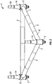
- the tidal flow energy generation structure 1 comprises a freestanding structural frame assembly comprising steel tubes 2.
- the frame assembly comprises welded tubular steel corner modules 3.
- the corner units are interconnected by lengths of the steel tubes 2.
- the structure as shown in the drawings is triangular in footprint and this may for certain deployment scenarios be preferred however other shape footprints (such as rectangular) are also envisaged in such arrangements the angular configuration of the corner modules 3 will of course be different to that shown and described in relation to the drawings.
- the use of a triangular, 3 corner module construction has advantages in the stability of three point contact on the sea bed.
- the corner modules 3 comprise first and second angled limbs 7, 8 extending at an angle of 60 degrees to one another.
- the respective corner module 3 includes a mount 14 to receive and locate a shaft 20 of a respective nacelle 9.
- the corner module 3 and interconnecting tubes 2 include respective flanges for bolting to one another.
- the tubes 2 may be configured to permit water to flood into and drain out of the tubes 2 which enables in sinking of the structure to deploy on the sea bed and pumping out for lifting.
- the structure is held in position by its own mass and lack of buoyancy due to flooding of the tubes 2 and end modules 3.
- the tubes 2 are positioned in the boundary layer close to the seabed and the structure has a large base area relative to height. This minimises potential overturning moment. Horizontal drag is minimised due to using single large diameter tubes 2 as the main interconnecting support for the frame.
- solid frame beams of metal construction may be used as an alternative to hollow tubes.
- the structure forms a mounting base for the turbines 9 mounted at each corner module 3, the support shaft 20 of a respective turbine 9 being received within the respective nacelle structure 14 such that the turbines can rotate about the longitudinal axis of the respective support shaft 20.
- the turbine shaft mounting bearings and other power generation components can be housed within the nacelle structures 14, such that it is only required to mount the shaft into the pre-assembled generation structure when positioned on the sea bed. Power is transmitted from the corner mounted turbines 19 to onshore by means of appropriate cable as is well known in the marine renewables industry.
- the structure is designed to be installed and removed entirely from surface vessels.
- the structure is designed to be installed onto a previously surveyed site in the time interval that represents slack water between the ebb and flood of the tide. This time may vary from 10 to 90 minutes.
- the unit may be restricted from being deployed outside the timeframe as the drag on the structure from water movement could destabilise the surface vessel.
- sea bed penetrating support foot structures 15 are utilised including a penetrating tip which is arranged to penetrate into the sea bed to a significant degree under the weight of the tidal energy generation structure, in accordance with the invention.
- the sea bed penetrating support foot structure 15 as shown in the drawings has a generally triangular tip plate 26 welded to a horizontal disc 31, the disc 31 being connected below the corner module 3 by welded support stanchions 36 which define a spacing section above disc 31.
- the triangular tip plate 26 is braced by support plates 32 welded to the tip plate 26 and the disc 31.
- the inclined sides 41, 42 of the tip plate 26 are typically inclined at a mutual angle of 60 degrees to meet at a vertex 43. The smaller the apex angle between the opposed inclined surfaces, the more significant is the penetration. Accordingly, the apex angle between the opposed inclined surfaces is preferably 70 degrees or less (more preferably 60 degrees or less).
- a key aspect of the invention is that the structure can be deployed quickly (for example during slack water) and without extensive preparation to the sea bed. This is achieved by using the structure's own weight to anchor the structure in place. A large footprint area for the tidal energy generation structure 1 (and triangular footprint) aid in the robust positioning of the structure.
- the respective foot structures pre-assembled with the structure, the support foot structures being fixed in position relative to the structure before lowering to the sea bed. This requires minimum further adjustment post deployment in the short time available.
- the weight of the entire structure is used to embed the penetrating foot 15 into the sea bed there is no requirement for the penetrating foot structure 15 itself to be particularly massive or heavy. This benefit is not disclosed in the prior art, and enables the penetrating tip to be made of a metal plate construction, for example.
- the sea bed penetrating support foot structure 15 is shown most clearly in figures 3 and 4 .
- the sea bed penetrating support foot structure 15 includes a penetrating tip 25 which is designed to penetrate into the sea bed surface under the weight of the structure 1 as the structure 1 is deployed.
- each corner module 5 is provided with a separate, identical sea bed penetrating support foot structure 15, providing 3 points of contact. These relatively few points of contact enables sufficient weight to be transferred via the respective sea bed penetrating support foot structure 15 to enable the penetrating tip 25 to break the sea bed surface, and sink into the material of the sea bed, in order to anchor the structure 1.
- This design is contrary to the way in which conventional structures are mounted to the sea bed in which prepared foundations are typically utilised and the setting area of the surface foundation would be as large as possible in order to minimise the pressure on the foundation (to avoid degradation of the foundation).
- the welded support stanchions 36 which define the spacing section above the penetration limitation flange or disc 3, can sink into sedimentary deposits to provided added fixing of the structure in position.
- the welded support stanchions 36 which define the spacing section taper from a relatively wider upper portion to a relatively narrower portion at the penetration limitation flange or disc 3.
- the design of the sea bed penetrating support foot structure 15 provides that when the tidal energy generation structure has been deployed on the sea bed, the sea bed penetrating support foot structure 15 ensures that the penetrating tip plate 26 breaks the surface and penetrates to a significant degree. The sea bed penetrating support foot structure 15 then provides significant resistance to lateral motion of the structure over the sea bed.
- the penetration depth is typically at least 100mm.
- the plate 31 provides a penetration depth limitation means to prevent the tip penetrating beyond a predetermined distance into the sea bed. Alternatively other means such as a stop, flange or plate could be used for this purpose.
- the invention provides for a largely preassembled structure for mounting several turbines, in which the weight of the structure acts to ensure penetration of spaced penetration foot structures sufficiently to mount the structure in place.
- the pre-assembled structure utilises pre-assembled frame connected nacelle structures provided with respective penetrating feet pre-assembled prior to lowering to the sea-bed.
Landscapes
- Engineering & Computer Science (AREA)
- General Engineering & Computer Science (AREA)
- Mechanical Engineering (AREA)
- Chemical & Material Sciences (AREA)
- Combustion & Propulsion (AREA)
- Civil Engineering (AREA)
- Structural Engineering (AREA)
- Power Engineering (AREA)
- Life Sciences & Earth Sciences (AREA)
- General Life Sciences & Earth Sciences (AREA)
- Oceanography (AREA)
- Other Liquid Machine Or Engine Such As Wave Power Use (AREA)
Claims (11)
- Structure de production d'énergie marémotrice (1) destinée à être montée sur un fond marin, comprenant une pluralité de structures de pied support pénétrant le fond marin (15) préassemblées avec la structure et déployées avec la structure lors de la mise en place sur le fond marin, les structures de pied support pénétrant le fond marin (15) étant assemblées dans une position fixe les unes par rapport aux autres sur un cadre rigide et comprenant une pointe pénétrante (25) respective conçue pour pénétrer dans la surface du fond marin sous le poids de la structure de production d'énergie marémotrice (1) lorsqu'elles sont déployées sur le fond marin, la pointe pénétrante (25) comprenant une plaque généralement triangulaire ayant un sommet, la structure de pied support pénétrant le fond marin (15) comprenant un moyen de limitation de profondeur de pénétration qui empêche la pointe (26) de pénétrer dans le fond marin au-delà d'une distance prédéterminée, le moyen de limitation de profondeur de pénétration comprend un disque ou plaque faisant bride d'arrêt positionnée au-dessus de la pointe pénétrante (25) et s'étendant vers l'extérieur à partir de la pointe pénétrante (25) au niveau d'une position espacée vers le haut à partir de la pointe (26).
- Structure de production d'énergie marémotrice (1) selon la revendication 1, la structure (1) étant préassemblée et comprenant des structures de nacelle connectées au cadre (14) et une pluralité de structures de pied support pénétrant le fond marin (15) préassemblées avec la structure, les structures de pied support (15) étant fixées en position par rapport à la structure avant d'être abaissées sur le fond marin.
- Structure de production d'énergie marémotrice (1) selon la revendication 2, la structure (1) étant munie d'une structure de pied support espacée sous chaque nacelle connectée au cadre (14), ayant chacune une pointe pénétrante respective qui pénètre dans le fond marin dans une large mesure.
- Structure de production d'énergie marémotrice selon l'une quelconque des revendications précédentes, dans laquelle la pointe pénétrante (25) des structures de pied support pénétrant le fond marin a des surfaces opposées inclinées se terminant au niveau d'un sommet.
- Structure de production d'énergie marémotrice selon la revendication 4, dans laquelle l'angle du sommet des structures de pied support pénétrant le fond marin entre les surfaces opposées inclinées est inférieur ou égal à 70 degrés.
- Structure de production d'énergie marémotrice selon la revendication 5, dans laquelle l'angle du sommet des structures de pied support pénétrant le fond marin entre les surfaces opposées inclinées est inférieur ou égal à 60 degrés.
- Structure de production d'énergie marémotrice selon l'une quelconque des revendications précédentes, la structure comprenant une section d'espacement située au-dessus de la structure de pied support pénétrant le fond marin.
- Structure de production d'énergie marémotrice selon la revendication 7, dans laquelle la section d'espacement est située au-dessus du moyen de limitation de profondeur de pénétration.
- Structure de production d'énergie marémotrice selon la revendication 7 ou 8, dans laquelle la section d'espacement est à section décroissante d'une partie supérieure relativement large à une partie relativement plus étroite adjacente à la structure de pied support pénétrant le fond marin.
- Structure de production d'énergie marémotrice à montage sur fond marin (1) selon l'une quelconque des revendications précédentes, la structure de production d'énergie (1) ayant un cadre généralement triangulaire, et la structure étant munie de trois structures de pied support pénétrant le fond marin (15), de préférence espacées au niveau des sommets du cadre triangulaire.
- Procédé de fixation d'une structure de production d'énergie marémotrice à montage sur fond marin (1) en position sur le fond marin, le procédé consistant à abaisser une structure préassemblée comprenant des structures de nacelle connectées à un cadre (14) et une pluralité de structures de pied support pénétrant le fond marin (15) préassemblées avec la structure, les structures de pied support (15) étant fixées en position par rapport à la structure avant d'être abaissées sur le fond marin et comprenant une pointe pénétrante (25) conçue pour pénétrer dans le fond marin dans une large mesure sous le poids de la structure de production d'énergie marémotrice, la structure de production d'énergie marémotrice à montage sur fond marin (1) étant munie d'une pluralité de structures de pied support espacées sous chaque nacelle connectée au cadre (9), chaque structure de pied support espacée comprenant une pointe pénétrante respective pour permettre à chaque structure de la pluralité de structures de pied support espacées de pénétrer dans le fond marin dans une large mesure, la pointe pénétrante (25) comprenant une plaque généralement triangulaire ayant un sommet, les structures de pied support espacées comprenant un moyen de limitation de profondeur de pénétration comprenant un disque ou plaque faisant bride d'arrêt positionnée au-dessus de la pointe pénétrante (25) et s'étendant vers l'extérieur à partir de la pointe pénétrante (25) au niveau d'une position espacée vers le haut à partir de la pointe.
Applications Claiming Priority (2)
| Application Number | Priority Date | Filing Date | Title |
|---|---|---|---|
| GBGB1019080.9A GB201019080D0 (en) | 2010-11-11 | 2010-11-11 | Tidal flow generation structures |
| PCT/GB2011/052197 WO2012063076A2 (fr) | 2010-11-11 | 2011-11-11 | Structures de production d'énergie marémotrice |
Publications (2)
| Publication Number | Publication Date |
|---|---|
| EP2638277A2 EP2638277A2 (fr) | 2013-09-18 |
| EP2638277B1 true EP2638277B1 (fr) | 2018-03-14 |
Family
ID=43431303
Family Applications (1)
| Application Number | Title | Priority Date | Filing Date |
|---|---|---|---|
| EP11808265.0A Not-in-force EP2638277B1 (fr) | 2010-11-11 | 2011-11-11 | Structures de production d'énergie marémotrice |
Country Status (5)
| Country | Link |
|---|---|
| US (1) | US20130243527A1 (fr) |
| EP (1) | EP2638277B1 (fr) |
| CA (1) | CA2817321A1 (fr) |
| GB (1) | GB201019080D0 (fr) |
| WO (1) | WO2012063076A2 (fr) |
Families Citing this family (4)
| Publication number | Priority date | Publication date | Assignee | Title |
|---|---|---|---|---|
| CA3127836A1 (fr) | 2019-01-18 | 2020-07-23 | Telesystem Energy Ltd. | Palier magnetique passif pour machines rotatives et machines rotatives integrant ledit palier, comprenant des turbines de production d'energie |
| DK3938646T3 (da) | 2019-03-14 | 2024-04-08 | Telesysteme Energie Ltee | Flertrinskappe til en hydrokinetisk turbine |
| CN111622889B (zh) * | 2020-06-10 | 2025-02-07 | 杭州林黄丁新能源研究院有限公司 | 大型潮流能发电装置及其总成平台 |
| US11608605B1 (en) * | 2022-05-16 | 2023-03-21 | Yona Becher | Offshore ocean renewable energy hydro-turbine unit |
Family Cites Families (5)
| Publication number | Priority date | Publication date | Assignee | Title |
|---|---|---|---|---|
| US4181455A (en) * | 1978-05-17 | 1980-01-01 | Tad Stanwick | Apparatus for generating rotary power in a deep-sea environment |
| GB0329589D0 (en) * | 2003-12-20 | 2004-01-28 | Marine Current Turbines Ltd | Articulated false sea bed |
| GB2455784B (en) * | 2007-12-21 | 2012-10-24 | Tidal Energy Ltd | Tidal flow power generation |
| FR2935005B1 (fr) | 2008-08-14 | 2013-08-16 | Institut Nat Polytechnique De Grenoble | Structure d'assise d'une turbomachine hydraulique |
| EP2199602A1 (fr) * | 2008-12-18 | 2010-06-23 | OpenHydro IP Limited | Procédé de sécurisation d'une turbine hydroélectrique sur un site de déploiement et une turbine hydroélectrique |
-
2010
- 2010-11-11 GB GBGB1019080.9A patent/GB201019080D0/en not_active Ceased
-
2011
- 2011-11-11 WO PCT/GB2011/052197 patent/WO2012063076A2/fr not_active Ceased
- 2011-11-11 US US13/884,292 patent/US20130243527A1/en not_active Abandoned
- 2011-11-11 EP EP11808265.0A patent/EP2638277B1/fr not_active Not-in-force
- 2011-11-11 CA CA2817321A patent/CA2817321A1/fr not_active Abandoned
Also Published As
| Publication number | Publication date |
|---|---|
| GB201019080D0 (en) | 2010-12-29 |
| WO2012063076A2 (fr) | 2012-05-18 |
| US20130243527A1 (en) | 2013-09-19 |
| WO2012063076A3 (fr) | 2012-08-16 |
| CA2817321A1 (fr) | 2012-05-18 |
| EP2638277A2 (fr) | 2013-09-18 |
Similar Documents
| Publication | Publication Date | Title |
|---|---|---|
| Musial et al. | Feasibility of floating platform systems for wind turbines | |
| KR101623741B1 (ko) | 해상 풍력발전 지지구조물 및 그 시공방법 | |
| KR101459649B1 (ko) | 해상 지지구조물 설치를 위한 이중 부유구조체 및 이를 이용한 해상 지지구조물 시공 방법 | |
| CA2587877C (fr) | Support et fondation de structure offshore destines a une turbine eolienne et procede d'assemblage associe | |
| Koschinski et al. | Development of noise mitigation measures in offshore wind farm construction | |
| DK2931977T3 (en) | PROCEDURE FOR ANCHORING A FOUNDATION STRUCTURE AND FOUNDATION STRUCTURE | |
| US20200407021A1 (en) | Multiline Ring Anchor and Installation Method | |
| KR20130124457A (ko) | 해저 정박 시스템 및 방법 | |
| US12442359B2 (en) | Windmill construction and a method for assembly of a windmill construction | |
| JP2008111406A (ja) | 洋上風力発電施設およびその施工方法 | |
| Malhotra | Design and construction considerations for offshore wind turbine foundations in North America | |
| GB2524460A (en) | Offshore foundation | |
| Malhotra | Design and construction considerations for offshore wind turbine foundations | |
| EP2638277B1 (fr) | Structures de production d'énergie marémotrice | |
| JP2005194792A (ja) | 洋上風力発電装置の基礎および洋上風力発電装置の据付方法 | |
| JP2016084660A (ja) | 洋上風力発電装置の基礎構造 | |
| KR101304934B1 (ko) | 멀티복합하이브리드기초형 해상풍력타워 | |
| KR20200114517A (ko) | 회전형 해양구조물, 그 시공방법 및 이를 이용한 발전시스템 | |
| JP2001248535A (ja) | 風力発電装置 | |
| KR101384168B1 (ko) | 위치센서를 이용한 해상풍력 발전기의 기초슬래브 설치 방법 | |
| KR102098658B1 (ko) | 권취장치탑재선을 이용한 부유식 구조물 계류방법 및 이에 사용되는 부유식 구조물 | |
| Stevens et al. | Mooring anchors for marine renewable energy foundations | |
| Bertalot et al. | Anchoring Floating Wind Turbines | |
| EP2189576A1 (fr) | Système de fondation pour structures marine en eaux profondes | |
| KR101332483B1 (ko) | 해상 풍력 발전용 지지구조물 및 이의 건설 방법 |
Legal Events
| Date | Code | Title | Description |
|---|---|---|---|
| PUAI | Public reference made under article 153(3) epc to a published international application that has entered the european phase |
Free format text: ORIGINAL CODE: 0009012 |
|
| 17P | Request for examination filed |
Effective date: 20130517 |
|
| AK | Designated contracting states |
Kind code of ref document: A2 Designated state(s): AL AT BE BG CH CY CZ DE DK EE ES FI FR GB GR HR HU IE IS IT LI LT LU LV MC MK MT NL NO PL PT RO RS SE SI SK SM TR |
|
| DAX | Request for extension of the european patent (deleted) | ||
| 17Q | First examination report despatched |
Effective date: 20150422 |
|
| GRAP | Despatch of communication of intention to grant a patent |
Free format text: ORIGINAL CODE: EPIDOSNIGR1 |
|
| INTG | Intention to grant announced |
Effective date: 20171018 |
|
| GRAS | Grant fee paid |
Free format text: ORIGINAL CODE: EPIDOSNIGR3 |
|
| GRAA | (expected) grant |
Free format text: ORIGINAL CODE: 0009210 |
|
| AK | Designated contracting states |
Kind code of ref document: B1 Designated state(s): AL AT BE BG CH CY CZ DE DK EE ES FI FR GB GR HR HU IE IS IT LI LT LU LV MC MK MT NL NO PL PT RO RS SE SI SK SM TR |
|
| REG | Reference to a national code |
Ref country code: GB Ref legal event code: FG4D |
|
| REG | Reference to a national code |
Ref country code: CH Ref legal event code: EP Ref country code: AT Ref legal event code: REF Ref document number: 979149 Country of ref document: AT Kind code of ref document: T Effective date: 20180315 |
|
| REG | Reference to a national code |
Ref country code: IE Ref legal event code: FG4D |
|
| REG | Reference to a national code |
Ref country code: DE Ref legal event code: R096 Ref document number: 602011046543 Country of ref document: DE |
|
| REG | Reference to a national code |
Ref country code: NL Ref legal event code: MP Effective date: 20180314 |
|
| REG | Reference to a national code |
Ref country code: LT Ref legal event code: MG4D |
|
| PG25 | Lapsed in a contracting state [announced via postgrant information from national office to epo] |
Ref country code: NO Free format text: LAPSE BECAUSE OF FAILURE TO SUBMIT A TRANSLATION OF THE DESCRIPTION OR TO PAY THE FEE WITHIN THE PRESCRIBED TIME-LIMIT Effective date: 20180614 Ref country code: CY Free format text: LAPSE BECAUSE OF FAILURE TO SUBMIT A TRANSLATION OF THE DESCRIPTION OR TO PAY THE FEE WITHIN THE PRESCRIBED TIME-LIMIT Effective date: 20180314 Ref country code: HR Free format text: LAPSE BECAUSE OF FAILURE TO SUBMIT A TRANSLATION OF THE DESCRIPTION OR TO PAY THE FEE WITHIN THE PRESCRIBED TIME-LIMIT Effective date: 20180314 Ref country code: LT Free format text: LAPSE BECAUSE OF FAILURE TO SUBMIT A TRANSLATION OF THE DESCRIPTION OR TO PAY THE FEE WITHIN THE PRESCRIBED TIME-LIMIT Effective date: 20180314 Ref country code: ES Free format text: LAPSE BECAUSE OF FAILURE TO SUBMIT A TRANSLATION OF THE DESCRIPTION OR TO PAY THE FEE WITHIN THE PRESCRIBED TIME-LIMIT Effective date: 20180314 Ref country code: FI Free format text: LAPSE BECAUSE OF FAILURE TO SUBMIT A TRANSLATION OF THE DESCRIPTION OR TO PAY THE FEE WITHIN THE PRESCRIBED TIME-LIMIT Effective date: 20180314 |
|
| REG | Reference to a national code |
Ref country code: AT Ref legal event code: MK05 Ref document number: 979149 Country of ref document: AT Kind code of ref document: T Effective date: 20180314 |
|
| PG25 | Lapsed in a contracting state [announced via postgrant information from national office to epo] |
Ref country code: RS Free format text: LAPSE BECAUSE OF FAILURE TO SUBMIT A TRANSLATION OF THE DESCRIPTION OR TO PAY THE FEE WITHIN THE PRESCRIBED TIME-LIMIT Effective date: 20180314 Ref country code: GR Free format text: LAPSE BECAUSE OF FAILURE TO SUBMIT A TRANSLATION OF THE DESCRIPTION OR TO PAY THE FEE WITHIN THE PRESCRIBED TIME-LIMIT Effective date: 20180615 Ref country code: SE Free format text: LAPSE BECAUSE OF FAILURE TO SUBMIT A TRANSLATION OF THE DESCRIPTION OR TO PAY THE FEE WITHIN THE PRESCRIBED TIME-LIMIT Effective date: 20180314 Ref country code: BG Free format text: LAPSE BECAUSE OF FAILURE TO SUBMIT A TRANSLATION OF THE DESCRIPTION OR TO PAY THE FEE WITHIN THE PRESCRIBED TIME-LIMIT Effective date: 20180614 Ref country code: LV Free format text: LAPSE BECAUSE OF FAILURE TO SUBMIT A TRANSLATION OF THE DESCRIPTION OR TO PAY THE FEE WITHIN THE PRESCRIBED TIME-LIMIT Effective date: 20180314 |
|
| PG25 | Lapsed in a contracting state [announced via postgrant information from national office to epo] |
Ref country code: NL Free format text: LAPSE BECAUSE OF FAILURE TO SUBMIT A TRANSLATION OF THE DESCRIPTION OR TO PAY THE FEE WITHIN THE PRESCRIBED TIME-LIMIT Effective date: 20180314 Ref country code: AL Free format text: LAPSE BECAUSE OF FAILURE TO SUBMIT A TRANSLATION OF THE DESCRIPTION OR TO PAY THE FEE WITHIN THE PRESCRIBED TIME-LIMIT Effective date: 20180314 Ref country code: PL Free format text: LAPSE BECAUSE OF FAILURE TO SUBMIT A TRANSLATION OF THE DESCRIPTION OR TO PAY THE FEE WITHIN THE PRESCRIBED TIME-LIMIT Effective date: 20180314 Ref country code: IT Free format text: LAPSE BECAUSE OF FAILURE TO SUBMIT A TRANSLATION OF THE DESCRIPTION OR TO PAY THE FEE WITHIN THE PRESCRIBED TIME-LIMIT Effective date: 20180314 Ref country code: RO Free format text: LAPSE BECAUSE OF FAILURE TO SUBMIT A TRANSLATION OF THE DESCRIPTION OR TO PAY THE FEE WITHIN THE PRESCRIBED TIME-LIMIT Effective date: 20180314 Ref country code: EE Free format text: LAPSE BECAUSE OF FAILURE TO SUBMIT A TRANSLATION OF THE DESCRIPTION OR TO PAY THE FEE WITHIN THE PRESCRIBED TIME-LIMIT Effective date: 20180314 |
|
| PG25 | Lapsed in a contracting state [announced via postgrant information from national office to epo] |
Ref country code: CZ Free format text: LAPSE BECAUSE OF FAILURE TO SUBMIT A TRANSLATION OF THE DESCRIPTION OR TO PAY THE FEE WITHIN THE PRESCRIBED TIME-LIMIT Effective date: 20180314 Ref country code: SM Free format text: LAPSE BECAUSE OF FAILURE TO SUBMIT A TRANSLATION OF THE DESCRIPTION OR TO PAY THE FEE WITHIN THE PRESCRIBED TIME-LIMIT Effective date: 20180314 Ref country code: AT Free format text: LAPSE BECAUSE OF FAILURE TO SUBMIT A TRANSLATION OF THE DESCRIPTION OR TO PAY THE FEE WITHIN THE PRESCRIBED TIME-LIMIT Effective date: 20180314 Ref country code: SK Free format text: LAPSE BECAUSE OF FAILURE TO SUBMIT A TRANSLATION OF THE DESCRIPTION OR TO PAY THE FEE WITHIN THE PRESCRIBED TIME-LIMIT Effective date: 20180314 |
|
| REG | Reference to a national code |
Ref country code: DE Ref legal event code: R097 Ref document number: 602011046543 Country of ref document: DE |
|
| PG25 | Lapsed in a contracting state [announced via postgrant information from national office to epo] |
Ref country code: PT Free format text: LAPSE BECAUSE OF FAILURE TO SUBMIT A TRANSLATION OF THE DESCRIPTION OR TO PAY THE FEE WITHIN THE PRESCRIBED TIME-LIMIT Effective date: 20180716 |
|
| PLBE | No opposition filed within time limit |
Free format text: ORIGINAL CODE: 0009261 |
|
| STAA | Information on the status of an ep patent application or granted ep patent |
Free format text: STATUS: NO OPPOSITION FILED WITHIN TIME LIMIT |
|
| PG25 | Lapsed in a contracting state [announced via postgrant information from national office to epo] |
Ref country code: DK Free format text: LAPSE BECAUSE OF FAILURE TO SUBMIT A TRANSLATION OF THE DESCRIPTION OR TO PAY THE FEE WITHIN THE PRESCRIBED TIME-LIMIT Effective date: 20180314 |
|
| 26N | No opposition filed |
Effective date: 20181217 |
|
| PG25 | Lapsed in a contracting state [announced via postgrant information from national office to epo] |
Ref country code: SI Free format text: LAPSE BECAUSE OF FAILURE TO SUBMIT A TRANSLATION OF THE DESCRIPTION OR TO PAY THE FEE WITHIN THE PRESCRIBED TIME-LIMIT Effective date: 20180314 |
|
| REG | Reference to a national code |
Ref country code: DE Ref legal event code: R119 Ref document number: 602011046543 Country of ref document: DE |
|
| REG | Reference to a national code |
Ref country code: CH Ref legal event code: PL |
|
| GBPC | Gb: european patent ceased through non-payment of renewal fee |
Effective date: 20181111 |
|
| PG25 | Lapsed in a contracting state [announced via postgrant information from national office to epo] |
Ref country code: LU Free format text: LAPSE BECAUSE OF NON-PAYMENT OF DUE FEES Effective date: 20181111 Ref country code: MC Free format text: LAPSE BECAUSE OF FAILURE TO SUBMIT A TRANSLATION OF THE DESCRIPTION OR TO PAY THE FEE WITHIN THE PRESCRIBED TIME-LIMIT Effective date: 20180314 |
|
| REG | Reference to a national code |
Ref country code: BE Ref legal event code: MM Effective date: 20181130 |
|
| REG | Reference to a national code |
Ref country code: IE Ref legal event code: MM4A |
|
| PG25 | Lapsed in a contracting state [announced via postgrant information from national office to epo] |
Ref country code: LI Free format text: LAPSE BECAUSE OF NON-PAYMENT OF DUE FEES Effective date: 20181130 Ref country code: CH Free format text: LAPSE BECAUSE OF NON-PAYMENT OF DUE FEES Effective date: 20181130 |
|
| PG25 | Lapsed in a contracting state [announced via postgrant information from national office to epo] |
Ref country code: DE Free format text: LAPSE BECAUSE OF NON-PAYMENT OF DUE FEES Effective date: 20190601 Ref country code: FR Free format text: LAPSE BECAUSE OF NON-PAYMENT OF DUE FEES Effective date: 20181130 Ref country code: IE Free format text: LAPSE BECAUSE OF NON-PAYMENT OF DUE FEES Effective date: 20181111 |
|
| PG25 | Lapsed in a contracting state [announced via postgrant information from national office to epo] |
Ref country code: BE Free format text: LAPSE BECAUSE OF NON-PAYMENT OF DUE FEES Effective date: 20181130 |
|
| PG25 | Lapsed in a contracting state [announced via postgrant information from national office to epo] |
Ref country code: GB Free format text: LAPSE BECAUSE OF NON-PAYMENT OF DUE FEES Effective date: 20181111 |
|
| PG25 | Lapsed in a contracting state [announced via postgrant information from national office to epo] |
Ref country code: MT Free format text: LAPSE BECAUSE OF NON-PAYMENT OF DUE FEES Effective date: 20181111 |
|
| PG25 | Lapsed in a contracting state [announced via postgrant information from national office to epo] |
Ref country code: TR Free format text: LAPSE BECAUSE OF FAILURE TO SUBMIT A TRANSLATION OF THE DESCRIPTION OR TO PAY THE FEE WITHIN THE PRESCRIBED TIME-LIMIT Effective date: 20180314 |
|
| PG25 | Lapsed in a contracting state [announced via postgrant information from national office to epo] |
Ref country code: HU Free format text: LAPSE BECAUSE OF FAILURE TO SUBMIT A TRANSLATION OF THE DESCRIPTION OR TO PAY THE FEE WITHIN THE PRESCRIBED TIME-LIMIT; INVALID AB INITIO Effective date: 20111111 Ref country code: MK Free format text: LAPSE BECAUSE OF NON-PAYMENT OF DUE FEES Effective date: 20180314 |
|
| PG25 | Lapsed in a contracting state [announced via postgrant information from national office to epo] |
Ref country code: IS Free format text: LAPSE BECAUSE OF FAILURE TO SUBMIT A TRANSLATION OF THE DESCRIPTION OR TO PAY THE FEE WITHIN THE PRESCRIBED TIME-LIMIT Effective date: 20180714 |