EP2639006A1 - Friction stir welding device - Google Patents
Friction stir welding device Download PDFInfo
- Publication number
- EP2639006A1 EP2639006A1 EP11873951.5A EP11873951A EP2639006A1 EP 2639006 A1 EP2639006 A1 EP 2639006A1 EP 11873951 A EP11873951 A EP 11873951A EP 2639006 A1 EP2639006 A1 EP 2639006A1
- Authority
- EP
- European Patent Office
- Prior art keywords
- rotating body
- joint
- friction stir
- stir welding
- upper rotating
- Prior art date
- Legal status (The legal status is an assumption and is not a legal conclusion. Google has not performed a legal analysis and makes no representation as to the accuracy of the status listed.)
- Granted
Links
Images


Classifications
-
- B—PERFORMING OPERATIONS; TRANSPORTING
- B23—MACHINE TOOLS; METAL-WORKING NOT OTHERWISE PROVIDED FOR
- B23K—SOLDERING OR UNSOLDERING; WELDING; CLADDING OR PLATING BY SOLDERING OR WELDING; CUTTING BY APPLYING HEAT LOCALLY, e.g. FLAME CUTTING; WORKING BY LASER BEAM
- B23K20/00—Non-electric welding by applying impact or other pressure, with or without the application of heat, e.g. cladding or plating
- B23K20/12—Non-electric welding by applying impact or other pressure, with or without the application of heat, e.g. cladding or plating the heat being generated by friction; Friction welding
- B23K20/122—Non-electric welding by applying impact or other pressure, with or without the application of heat, e.g. cladding or plating the heat being generated by friction; Friction welding using a non-consumable tool, e.g. friction stir welding
- B23K20/123—Controlling or monitoring the welding process
-
- B—PERFORMING OPERATIONS; TRANSPORTING
- B23—MACHINE TOOLS; METAL-WORKING NOT OTHERWISE PROVIDED FOR
- B23K—SOLDERING OR UNSOLDERING; WELDING; CLADDING OR PLATING BY SOLDERING OR WELDING; CUTTING BY APPLYING HEAT LOCALLY, e.g. FLAME CUTTING; WORKING BY LASER BEAM
- B23K20/00—Non-electric welding by applying impact or other pressure, with or without the application of heat, e.g. cladding or plating
- B23K20/12—Non-electric welding by applying impact or other pressure, with or without the application of heat, e.g. cladding or plating the heat being generated by friction; Friction welding
- B23K20/122—Non-electric welding by applying impact or other pressure, with or without the application of heat, e.g. cladding or plating the heat being generated by friction; Friction welding using a non-consumable tool, e.g. friction stir welding
- B23K20/1245—Non-electric welding by applying impact or other pressure, with or without the application of heat, e.g. cladding or plating the heat being generated by friction; Friction welding using a non-consumable tool, e.g. friction stir welding characterised by the apparatus
- B23K20/126—Workpiece support, i.e. backing or clamping
-
- B—PERFORMING OPERATIONS; TRANSPORTING
- B23—MACHINE TOOLS; METAL-WORKING NOT OTHERWISE PROVIDED FOR
- B23K—SOLDERING OR UNSOLDERING; WELDING; CLADDING OR PLATING BY SOLDERING OR WELDING; CUTTING BY APPLYING HEAT LOCALLY, e.g. FLAME CUTTING; WORKING BY LASER BEAM
- B23K20/00—Non-electric welding by applying impact or other pressure, with or without the application of heat, e.g. cladding or plating
- B23K20/12—Non-electric welding by applying impact or other pressure, with or without the application of heat, e.g. cladding or plating the heat being generated by friction; Friction welding
- B23K20/122—Non-electric welding by applying impact or other pressure, with or without the application of heat, e.g. cladding or plating the heat being generated by friction; Friction welding using a non-consumable tool, e.g. friction stir welding
- B23K20/1225—Particular aspects of welding with a non-consumable tool
Definitions
- the present invention relates to a friction stir welding apparatus capable of controlling positions of an upper rotating body and a lower rotating body of a bobbin-type rotating tool and, more particularly, to a friction stir welding apparatus provided with a non-rotating member in a part in which the upper rotating body and the lower rotating body contact with members or pieces to be joined in order to improve a finished surface of a joint.
- Friction stir joining has a problem that excess heating to members or pieces to be joined results in coarse joining quality.
- Patent Document 1 listed below therefore proposes a friction stir welding apparatus shown in FIG. 10 .
- a spindle 111 is supported rotatably through a bearing 112 and coupled to a drive motor not shown.
- a lower end of the spindle 111 is supported by a tool head bearing 113 fixed to the housing 110.
- a probe 115 located in a holder is connected with the spindle 111 and protrudes out through an opening 116 of a housing lower part 114.
- a non-rotating slide part 118 is supported in the opening 116 so that this slide part 118 slides on the surface of a joint without rotating during friction stir welding.
- a rotating tool has a fixed-pin configuration and the non-rotating slide part 118 is provided separately from the spindle 111.
- the friction stir welding apparatus has to be configured to move the whole housing 110. Further, the slide part 118 slides on the surface of the joint and a shoulder surface of the probe 115 does not plunge into the members to be joined. In case a gap is generated in the joint, accordingly, a material does not flow in the gap to fill it. This may cause a joining failure.
- the present invention has been made to solve the above problems and has a purpose to provide a friction stir welding apparatus provided with a bobbin-type rotating tool in which a rotating body is movable up and down to achieve a good finished surface of a joint.
- one aspect of the invention provides a friction stir welding apparatus comprising a rotating tool including: an upper rotating body arranged to be adjustable in position in an axial direction by an actuator for upper rotating body; a lower rotating body formed integral with a rotating main rod extending through the upper rotating body and arranged to be adjustable in position in the axial direction by an actuator for lower rotating body; and a stirring part formed in the rotating main rod, the apparatus being configured such that the upper rotating body and the lower rotating body clamp therebetween a joint of members to be joined placed with their end faces butting each other and the stirring part is rotated to stir the joint by frictional heat to join the members, wherein the rotating tool includes a slide plate attached, through a thrust bearing, to one or both of end portions of the upper rotating body and the lower rotating body facing each other.
- the above friction stir welding apparatus preferably, further comprises: a load sensor to detect loads on the upper rotating body and the lower rotating body; a position sensor to detect positions of the upper rotating body and the lower rotating body; a position sensor to measure positions of the members to be joined; and a controller to execute load control to adjust the loads on the upper rotating body and the lower rotating body while clamping therebetween the joint and position control to adjust the positions of the upper rotating body and the lower rotating body.
- the position sensor includes a displacement sensor to measure positions of upper surfaces of the members to be joined, when the slide plate of the rotating tool is attached to only the upper rotating body, the controller drives each of the actuators based on information from each of the sensors to perform the load control and the position control on the upper rotating body and perform only the load control on the lower rotating body.
- the position sensor includes a displacement sensor to measure positions of upper surfaces of the members to be joined and a thickness sensor to measure a thickness of the joint of the members to be joined, when the slide plate of the rotating tool is attached to only the lower rotating body, the controller drives each of the actuators based on information from each of the sensors to perform the load control and the position control on the lower rotating body and perform only the load control on the upper rotating body.
- the position sensor includes a displacement sensor to measure positions of upper surfaces of the members to be joined and a thickness sensor to measure a thickness of the joint of the members to be joined, when the slide plates of the rotating tool are attached to the upper rotating body and the lower rotating body, the controller drives each of the actuators based on information from each of the sensors to perform the load control and the position control on the upper rotating body and the lower rotating body.
- the position control to be performed by the controller is configured to change the positions of the upper rotating body and the lower rotating body to follow the joint of the members to be joined in up-and-down directions.
- the position control to be performed by the controller is configured to adjust the position of the upper rotating body or the lower rotating body allowed to further plunge into the joint of the members to be joined.
- one or both of the upper rotating body and the lower rotating body include a slide plate or slide plates.
- This enables joining without generating a weld mark on a surface or surfaces with which the slide plate or slide plates contact.
- surface finishing using a grinder or the like is no longer necessary after joining.
- the surface(s) can be nearly directly used as a product surface(s). Since no depression is generated, the joint of the members to be joined does not need to be formed with a protrusion in advance. This can reduce a machining cost and save a relevant work, resulting in a reduced product cost.
- FIG. 1 is a conceptual diagram showing a structure of a friction stir welding apparatus in the present embodiment.
- This figure illustrates a side view of the apparatus seen in a direction perpendicular to a joining direction, in which a rotating tool 1 used for welding is moved leftward in the figure.
- two members to be joined (workpieces) 300 which are flat plates, are to be butt-welded together.
- FIG. 1 shows only one workpiece 300 located on a far side of the rotating tool 1 in the figure, and the other workpiece 300 located on a near side is not illustrated.
- a friction stir welding apparatus 10 includes a rotating tool 1 to weld the workpieces 300.
- the rotating tool 1 includes an upper rotating body 2, a lower rotating body 3, and a stirring part 4.
- the upper rotating body 2 and the lower rotating body 3 can be independently adjusted in position in up-and-down directions.
- the friction stir welding apparatus 10 is provided with hydraulic cylinders.
- an upper hydraulic cylinder 20A is provided for the upper rotating body 2.
- the upper hydraulic cylinder 20A is configured such that the upper rotating body 2 and a cylinder-shaped rod 11 are provided integrally, and the rod 11 is formed at its upper end with a piston 12.
- a cylinder body 13 is fixed, in which the rod 11 is slidably inserted. A sliding portion of the rod 11 is treated for sealing so that the rod 11 is inserted air-tightly.
- a pressurizing chamber is formed which is partitioned into upper and lower sections by the piston 12. The rod 11 is extended and retracted according to supply and discharge of operating oil to the pressurizing chamber to adjust the position of the upper rotating body 2.
- a lower hydraulic cylinder 20B is provided for the lower rotating body 3.
- the lower hydraulic cylinder 20B is configured such that a cavity is formed in the cylinder-shaped rod 11 to define a cylinder section, in which a rotating main rod 16 is inserted.
- the main rod 16 is formed with the lower rotating body 3 and the stirring part 4.
- This main rod 16 is slidably inserted in the cylinder-shaped rod 11 placed coaxially with the main rod 16.
- a sliding part of the main rod 16 is treated for sealing so that the main rod 16 is inserted air-tightly.
- the main rod 16 is formed at its upper end with a piston 17.
- the cavity forms a pressurizing chamber partitioned into upper and lower sections by the piston 17.
- the main rod 16 is extended and retracted according to supply and discharge of operating oil to the pressuring chamber to adjust the position of the lower rotating body 3.
- FIG. 1 illustrates only a configuration to adjust the positions of the upper rotating body 2 and the lower rotating body 3, but the friction stir welding apparatus 10 also includes a configuration to transmit rotational power. Specifically, the rotational output from a motor not shown is transmitted to the upper rotating body 2 of the tool 1. This rotation is further transmitted to the main rod 16 formed with a spline, thereby rotating the lower rotating body 3 and the stirring part 4 together with the upper rotating body 2.
- the hydraulic cylinders 20A and 20B are connected respectively to hydraulic devices 21A and 21B. These hydraulic devices 21A and 21B are connected to a shared hydraulic pump and a shared tank or to separate hydraulic pumps and tanks, which are not shown.
- a hydraulic circuit is accordingly configured including predetermined fluid devices such as a switch valve used to supply and discharge hydraulic oil with respect to the hydraulic cylinders 20A and 20B.
- the positions of the upper rotating body 2 and the lower rotating body 3 are adjusted by driving of those hydraulic devices 21A and 21B.
- the hydraulic cylinders 20A and 20B are provided respectively with stroke sensors 23 and 24 such as electromagnetic linear sensors to detect respective cylinder strokes.
- the friction stir welding apparatus 10 is further provided with a member measuring unit for measuring the position and the thickness of the workpiece 300 which is a member to be joined.
- a displacement sensor 25 to measure the position of an upper surface of the workpiece and a thickness sensor 29 to measure the thickness of the workpiece.
- the displacement sensor 25 is a differential transformer displacement sensor fixed to the base 50 and attached, at a lower end, with a contact element 26 through a movable rod 27. The contact element 26 is always urged downward by a coil spring 28 and is pressed against the upper surface of the workpiece 300 during friction stir.
- the displacement sensor 25 includes a primary coil and a secondary coil each being wound in cylindrical form in which a magnetic core is inserted to be movable up and down together with the rod 27.
- the rod 27 is moved up and down in association with the contact element 26 contacting with the workpiece 300, thereby moving the magnetic core, which changes mutual inductance between the coils and generates a voltage difference therebetween.
- the contact element 26 is provided with the thickness sensor 29 consisting of an ultrasonic transmitter-receiver device.
- the displacement sensor 25 and the thickness sensor 29 are located ahead of the rotating tool 1 in a forward-moving direction and provided respectively in right and left workpieces 300.
- FIG. 2 is a block diagram showing the friction stir welding apparatus 10.
- This apparatus 10 includes a controller 30 to control the hydraulic devices 21A and 21B.
- the controller 30 is connected to the stroke sensors 23 and 24 of the hydraulic cylinders 20A and 20B and member measuring units 31R and 31L.
- the controller 30 stores a control program to adjust the positions of the upper rotating body 2 and the lower rotating body 3 of the rotating tool 1 in order to control extension and retraction of the hydraulic cylinders 20A and 20B.
- a reference sign with a suffix "R” represents a component located on the right side with respect to the forward-moving direction
- a reference sign with a suffix "L” represents a component located on the left side.
- reference signs having no suffix "R" or "L” and right and left components are identical in configuration, those reference signs indicate both of right and left components. The same applies to the following description.
- a hydraulic sensor is provided in a hydraulic circuit forming the hydraulic devices 21A and 21B.
- a detection value of the hydraulic sensor is transmitted to the controller 30 to control constant loads to be applied to the upper rotating body 2 and the lower rotating body 3 clamping the workpieces 300 therebetween.
- the control is executed to adjust the loads for example at a load value of 1 kN so that the downward pressing force of the upper rotating body 2 on the upper surfaces of the workpieces 300 and the upward pressing force of the lower rotating body 3 on the lower surfaces of the workpieces 300 are balanced with each other.
- position control of the upper rotating body 2 and the lower rotating body 3 is performed in addition to the above load control.
- the load control in order to prevent the upper rotating body 2 and the lower rotating body 3 from plunging into the workpieces 300 more deeply than a certain value even when thermal characteristic changes become unstable.
- the rotating tool 1 used in the friction stir welding apparatus 10 is a so-called bobbin-type tool configured to rotate the upper rotating body 2 and the lower rotating body 3 while clamping the workpieces therebetween.
- the upper rotating body 2 is rotated upon receipt of power from the motor not shown and the rotation of the rotating body 2 is transmitted to the main rod 16, thereby rotating the stirring part 4 and the lower rotating body 3 together.
- FIG. 3 is a perspective view showing a joint during friction stir welding using the bobbin-type rotating tool.
- a weld mark 400 is generated on the surfaces of the workpieces 300.
- This weld mark 400 is formed as below.
- a bead portion 401 having semicircular streaks in a stripe pattern is formed on the trail of the tool 1. In the bead portion 401, the streaks form protrusions and depressions even though they are microscopic.
- burrs 402 On both of right and left sides of the bead portion 401, slight depressions 403 are formed inside burrs 402 which are generated when the softened and flowed material is extruded out by the upper rotating body 2 and the lower rotating body 3. After joining, therefore, it is necessary to smooth the surfaces of the workpieces 300 by reducing or removing the bead portion 401 and the burrs 402. Accordingly, a surface finishing work for example using a grinder or the like is performed. To smooth the surfaces without leaving the depressions 403 at that time, the workpieces 300 have to be processed in advance to make a thick joint 310.
- thermo-mechanically affected zone 410 is formed in a plastic flow region.
- the material is plastically deformed and flows under a high temperature below a melting point and thus receives large stress due to deformation during joining. This is because when the material present in front of the stirring part 4 is plastically deformed and flows backward, the material is divided by the stirring part 4 and passes through right and left narrow regions at a higher speed than a travel speed of the rotating tool 1.
- the strength of the thermo-mechanically affected zone 410 lowers. In friction stir welding, therefore, this region is preferably as narrow as possible.
- the friction stir welding apparatus 10 includes the rotating tool 1 characterized as below.
- FIGs. 4-6 are enlarged cross sectional views of three types of rotating tools 1. Focusing on shoulder surfaces for directly clamping the workpieces 300, rotating tools 1A, 1B, and 1C are respectively formed with shoulder surfaces that do not rotate together with the upper rotating body 2 and the lower rotating body 3. Specifically, when the shoulder surface is rotated, generating heat in the joint, the material of surface portions of the workpieces 300 is caused to plastically flow. The weld mark 400 and the thermo-mechanically affected zone 410 thus come about. From this point of view, it is intended to prevent heat generation caused by rotation of the upper rotating body 2 and the lower rotating body 3.
- the rotating tool 1A of a first type shown in FIG. 4 is configured such that an upper slide plate 5 is attached to a lower end of the upper rotating body 2 through a thrust bearing 41.
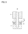
- the rotating tool 1B of a second type shown in FIG. 5 is configured such that a lower slide plate 6 is attached to an upper end of the lower rotating body 3 through a thrust bearing 42.
- the rotating tool 1C of a third type shown in FIG. 6 is configured by a combination of the first and second types, in which the upper slide plate 5 is attached to the lower end of the upper rotating body 2 through the thrust bearing 41 and the lower slide plate 6 is attached to the upper end of the lower rotating body 3 through the thrust bearing 42.
- the upper rotating body 2 and the lower rotating body 3 serve to hold down the material of a plastically flowing portion heated and allowed to flow, thereby preventing escape of the material.
- the stirring part 4 acts uniformly on the workpieces 300 in a thickness direction thereof to generate heat particularly in a contact portion most needing energy. This causes plastic flow of the material and enable welding. It is accordingly preferable not to rotate the upper rotating body 2 and the lower rotating body 3.
- the friction stir welding apparatus 10 is configured to rotate the upper rotating body 2 and the lower rotating body 3 together with the rotating main rod 16 including the stirring part 4. Further, the upper rotating body 2 and the lower rotating body 3 are moved up and down during the load control and the position control. This cannot be achieved by such a configuration that the slide part 118 is attached to the housing lower part 114 as the conventional example shown in FIG. 10 . Therefore, each of the rotating tools 1A, 1B, and 1C is provided with the upper slide plate 5 and/or the lower slide plate 6 in order to enable the load control and the position control of the upper rotating body 2 and the lower rotating body 3 and to block transmission of rotation of the shoulder surfaces contacting with the workpieces 300.
- the rotating tool 1 rotates and moves while the upper rotating body 2 and the lower rotating body 3 clamp the joint 310 therebetween.
- the joint 310 (see FIG. 3 ) at which end faces of the workpieces 300 are in butting contact with each other, heat is generated by rotation of the stirring part 4, thereby causing plastic flow of the material to join the portions.
- the upper rotating body 2 and the lower rotating body 3 press against the joint 310 from above and below at a constant load to prevent the heated material from flowing out.
- FIG. 7 is a perspective view showing a joining state during friction stir welding performed by use of the rotating tool 1A.
- the upper surface and the lower surface of the joint 310 are differently finished.
- the weld mark 400 comes about similarly as before.
- the bead portion 401 is formed in a stripe pattern and the burrs 402 are generated on both sides of the bead portion 401 in its width direction, and further slight depressions 403 are formed inside the burrs 402 by the material flowing outside as burrs.
- thermo-mechanically affected zone 420 as illustrated in the figure.
- plastic flow of the material is caused only by heat generated by rotation of the stirring part 4 and the lower rotating body 3. Comparing with the thermo-mechanically affected zone 410 shown in FIG. 3 , the material is not expanded to the upper surface side and therefore the region of the thermo-mechanically affected zone 420 is narrower. Further, since the upper slide plate 5 presses the material without rotating, the upper surface of the joint 310 becomes a flat smooth surface having no burrs and depressions such as in the weld mark 400 shown in FIG. 3 .
- the upper rotating body 2, the lower rotating body 3, and the stirring part 4 are rotated during friction stir welding, whereas the lower slide plate 6 contacting with the lower surfaces of the workpieces 300 is held in non-rotational state. Accordingly, the lower slide plate 6 slides on the surface of the joint 310 while remaining in non-rotational state as with the upper slide plate 5 mentioned above.
- the joint 310 after joining is obtained in a reversed state to the case shown in FIG. 7 . That is, in the upper surface with which the rotating upper rotating body 2 contacts, the weld mark 400 (see FIG. 3 ) is formed as in the conventional one, whereas the lower surface becomes a flat smooth surface having no burrs and depressions.
- the shape of a thermo-mechanically affected zone is also reversed to the shape of the thermo-mechanically affected zone 420 shown in FIG. 7 .
- the rotating tool 1A and the rotating tool 1B configured as above are preferably applied to the case where one of upper and lower surfaces of the workpieces 300 forms a design surface which will come under observation.
- the rotating tool 1C shown in FIG. 6 is used.
- the upper rotating body 2, the lower rotating body 3, and the stirring part 4 are rotated during friction stir welding, whereas the upper slide plate 5 and the lower slide plate 6 held in contact with the workpieces 300 are in non-rotational state.
- the thrust bearings 41 and 42 block the rotation. Even if the slide plates 5 and 6 are co-rotated slightly, the slide plates 5 and 6 slide on the surface of the joint 310 while remaining in almost non-rotational state.
- thermo-mechanically affected zone 430 is formed in a narrow region through which the stirring part 4 passes, and the affected zone 430 does not widen on upper and lower surface sides.
- FIG. 9 is a conceptual diagram to show the control to be performed on the upper rotating body 2 and the lower rotating body 3 of the rotating tool 1.
- FIG. 9 illustrates the rotating tool 1 for performing friction stir welding, seen from back in the forward-moving direction.
- the rotating tool 1 corresponds to the rotating tool 1A, 1B, or 1C, but the upper slide plate 5 and the lower slide plate 6 are omitted from FIG. 9 for simplicity. This omission of the upper slide plate 5 and the lower slide plate 6 also applies to FIGs. 1 and 2 .
- the rotating tool 1 rotates and moves to perform friction stir welding of the joint 310 at which the end faces of the workpieces 300 are in butting contact with each other.
- the load control is performed to cause the upper rotating body 2 and the lower rotating body 3 to pressurize the workpieces 300 from above and below at each constant load (e.g., 1kN).
- the position control of the upper rotating body 2 and the lower rotating body 3 is also conducted. Accordingly, the upper slide plate 5 and the lower slide plate 6 not illustrated are displaced together with the upper rotating body 2 and the lower rotating body 3 respectively integral therewith in the thickness direction (in up and down directions in the figure) of the workpieces 300.
- the member measuring units 31R and 31L provided on the right and left sides of the rotating tool 1 measure the positions of the upper surfaces of the right and left workpieces 300 through the displacement sensors 25.
- the distances to be measured by the displacement sensors 25 are referred to as the distances hR and hL from the lower surface of the base 50.
- the thickness sensors 29 the thicknesses tR and tL of the right and left workpieces 300R and 300L are measured respectively.
- the member measuring units 31R and 31L move ahead of the rotating tool 1.
- the contact elements 26 move in contact with the upper surfaces of the workpieces 300.
- the movable rods 27 move up and down as the heights of the upper surfaces of the workpieces 300 change.
- respective magnetic cores move inside the coils, generating a voltage difference, based on which the displacement of each upper component surface is detected.
- the thickness sensors 29 generate ultrasonic pulses toward the insides of the workpieces 300 and receive reflection waves reflected by the lower surfaces of the workpieces 300. The time needed to transmit/receive the pulses or waves is detected.
- a detection signal from each sensor is transmitted to the controller 30, in which the distances hR and hL and the thicknesses tR and tL are calculated based on those signals.
- the upper surface position hR and the lower surface position hR+tR of the workpiece 300R and the upper surface position hL and the lower surface position hL+tL of the workpiece 300L are calculated assuming that the lower surface of the base 50 is zero.
- detection signals from the stroke sensors 23 and 24 respectively provided in the hydraulic cylinders 20A and 20B are transmitted to the controller 30, and the positions of the shoulder surfaces 2a and 3a at which the upper rotating body 2 and the lower rotating body 3 contact with the workpieces 300 are calculated.
- the positions of the shoulder surface 5a and/or the shoulder surface 6a (see FIGS. 4 to 6 ) at which the slide plates 5 and 6 contact with the workpieces 300 are calculated.
- the position of each shoulder surface 2a and 5a and the position of each shoulder surface 3a and 6a are calculated respectively as the distances s2 and s3 from the lower surface of the base 50.
- the position control of the upper rotating body 2 and the lower rotating body 3 is performed to cause the upper rotating body 2 and the lower rotating body 3 to follow vertical changes of the joint 310.
- a joint located at butt ends of the workpieces may be displaced (undulation) in up and down directions when seen in a joining direction.
- the position control is performed to cause the upper rotating body 2 and the lower rotating body 3 to trace the undulating state of the joint 310.
- the upper surface positions of the right and left workpieces 300R and 300L are calculated respectively as hR and hL and the lower surface positions of the right and left workpieces 300R and 300L are calculated respectively as hR+tR and hL+tL.
- the position of the shoulder surface 2a of the upper rotating body 2 or the shoulder surface 5a of the upper slide plate 5 is calculated as s2 and the position of the shoulder surface 3a of the lower rotating body 3 or the shoulder surface 6a of the lower slide plate 6 is calculated as s3.
- the position control of the upper rotating body 2 and the lower rotating body 3 is executed. At that time, in the present embodiment, the position control of the upper slide plate 5 and/or the lower slide plate 6 each sliding on the surfaces of the workpieces 300 is performed.
- the upper rotating body 2 is subjected to the load control and the position control, while the lower rotating body 3 is subjected to only the load control.
- the upper rotating body 2 is subjected to only the load control, while the lower rotating body 3 is subjected to the load control and the position control.
- the upper rotating body 2 and the lower rotating body 3 are subjected to both the load control and the position control.
- the friction stir welding is performed by pressurizing the workpieces 300 from above and below at nearly constant loads.
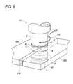
- the joint 310 at which the workpieces 300 are in butting relation is preferably provided with no gap as shown in FIG. 8 .
- a slight gap may occur in the joint 310 as shown in FIG. 7 due to process errors.
- the gap has to be filled with the plastically flowing material.
- the gap in the joint 310 could not be filled with only the material plastically flowed by the stirring part 4. This may cause joining failures.
- the rotating tool 1C even when the joint 310 includes a stepped surface as shown in FIG. 9 , it is expected to clamp the joint 310 from above and below by the shoulder surfaces 5a and 6a and join it by correcting the stepped surface.
- one of the upper and lower shoulder surfaces 5a and 6a serves as a backing support surface without generating heat. It is thus expected to similarly correct the stepped surface to a certain degree.
- the position control may also be executed to prevent the shoulder surface 2a of the upper rotating body 2 and the shoulder surface 3a of the lower rotating body 3 from too deeply plunging into the workpieces 300.
- the hydraulic cylinders 20A and 20B for load adjustment are extended or retracted in predetermined directions, thereby suppressing plunging or load increasing.
- the rotating bodies 2 and 3 initially contact with only one of both surfaces of each of the workpieces 300L and 300 R with small resistance.
- a limited contact depth is determined in advance, based on which the position control is performed. For instance, a set value is 0.05 mm for the workpieces 300 each having a thickness of 5 mm.
- the joint 310 has the step as shown in FIG. 9 , the upper or lower surface of one of the workpieces 300, the one being far from the upper shoulder surface 2a or the lower shoulder surface 3a, is set as a reference position from which the set value is determined as 0.05 mm.
- the positions hR+tR and hL+tL of the lower surfaces of the right and left workpieces 300R and 300L are calculated.
- the workpiece 300R is in a position farther from the shoulder surface 3a, i.e., in a higher position. It is thus arranged so that the contact depth g3R of the shoulder surface 3a with respect to the workpiece 300R does not exceed the set value, 0.05 mm.
- the load control is interrupted and the lower rotating body 3 is displaced in a direction to gradually return the shoulder surface 3a to the reference position.
- Another method is to lower a value for the load control when the position of the shoulder surface 3a reaches the set value. At that time, the lower rotating body 3 receives a larger reaction force than the load applied at a lowered load value, thereby displacing the lower rotating body 3 in the direction to move away.
- the rotating tool 1B In the case of the rotating tool 1B, on the other hand, only the upper surface side of the rotating tool 1B plunges into the workpieces 300.
- the positions of the upper surfaces of the right and left workpieces 300R and 300L are defined by hR and hL.
- the contact depth g2L of the shoulder surface 2a with respect to the workpiece 300L does not exceed the set value 0.05 mm.
- the load control is interrupted and the upper rotating body 2 is displaced in a direction to gradually return the shoulder surface 2a to the reference position.
- An alternative is to lower a value for the load control, so that the upper rotating body 2 receives a larger reaction force than the load, thereby displacing the upper rotating body 2 in the direction to move away.
- one or both of the upper rotating body 2 and the lower rotating body 3 are provided with the upper slide plate 5 and/or the lower slide plate 6 as shown in the rotating tools 1A, 1B, and 1C.
- This configuration enables joining of the workpieces 300 without generating the weld mark 400 in the surface with which the upper slide plate 5 or the lower slide plate 6 is placed in contact. Accordingly, there is no need to perform a surface finishing using a grinder or the like after joining. Such a surface can be substantially directly provided as a product surface. Further, since the depressions 403 are not generated, the joint 310 of the workpieces 300 does not need to be formed with a protrusion in advance. This can reduce a machining cost and save a relevant work, resulting in a reduced product cost.
Landscapes
- Engineering & Computer Science (AREA)
- Mechanical Engineering (AREA)
- Pressure Welding/Diffusion-Bonding (AREA)
Abstract
Description
- The present invention relates to a friction stir welding apparatus capable of controlling positions of an upper rotating body and a lower rotating body of a bobbin-type rotating tool and, more particularly, to a friction stir welding apparatus provided with a non-rotating member in a part in which the upper rotating body and the lower rotating body contact with members or pieces to be joined in order to improve a finished surface of a joint.
- Friction stir joining has a problem that excess heating to members or pieces to be joined results in coarse joining quality.
Patent Document 1 listed below therefore proposes a friction stir welding apparatus shown inFIG. 10 . In ahousing 110, aspindle 111 is supported rotatably through abearing 112 and coupled to a drive motor not shown. A lower end of thespindle 111 is supported by a tool head bearing 113 fixed to thehousing 110. Aprobe 115 located in a holder is connected with thespindle 111 and protrudes out through an opening 116 of a housinglower part 114. Anon-rotating slide part 118 is supported in theopening 116 so that thisslide part 118 slides on the surface of a joint without rotating during friction stir welding. -
- Patent Document 1:
JP-A-2009-537325 - Patent Document 2:
JP-A-2008-149331 - In such a conventional friction stir welding apparatus, a rotating tool has a fixed-pin configuration and the non-rotating
slide part 118 is provided separately from thespindle 111. Thus, when position adjustment of theslide part 118 in up-and-down directions is required according to the surface shapes of the members to be joined, the friction stir welding apparatus has to be configured to move thewhole housing 110. Further, theslide part 118 slides on the surface of the joint and a shoulder surface of theprobe 115 does not plunge into the members to be joined. In case a gap is generated in the joint, accordingly, a material does not flow in the gap to fill it. This may cause a joining failure. - The present invention has been made to solve the above problems and has a purpose to provide a friction stir welding apparatus provided with a bobbin-type rotating tool in which a rotating body is movable up and down to achieve a good finished surface of a joint.
- To achieve the above purpose, one aspect of the invention provides a friction stir welding apparatus comprising a rotating tool including: an upper rotating body arranged to be adjustable in position in an axial direction by an actuator for upper rotating body; a lower rotating body formed integral with a rotating main rod extending through the upper rotating body and arranged to be adjustable in position in the axial direction by an actuator for lower rotating body; and a stirring part formed in the rotating main rod, the apparatus being configured such that the upper rotating body and the lower rotating body clamp therebetween a joint of members to be joined placed with their end faces butting each other and the stirring part is rotated to stir the joint by frictional heat to join the members, wherein the rotating tool includes a slide plate attached, through a thrust bearing, to one or both of end portions of the upper rotating body and the lower rotating body facing each other.
- The above friction stir welding apparatus, preferably, further comprises: a load sensor to detect loads on the upper rotating body and the lower rotating body; a position sensor to detect positions of the upper rotating body and the lower rotating body; a position sensor to measure positions of the members to be joined; and a controller to execute load control to adjust the loads on the upper rotating body and the lower rotating body while clamping therebetween the joint and position control to adjust the positions of the upper rotating body and the lower rotating body.
- In the above friction stir welding apparatus, preferably, the position sensor includes a displacement sensor to measure positions of upper surfaces of the members to be joined, when the slide plate of the rotating tool is attached to only the upper rotating body, the controller drives each of the actuators based on information from each of the sensors to perform the load control and the position control on the upper rotating body and perform only the load control on the lower rotating body.
- In the above friction stir welding apparatus, preferably, the position sensor includes a displacement sensor to measure positions of upper surfaces of the members to be joined and a thickness sensor to measure a thickness of the joint of the members to be joined, when the slide plate of the rotating tool is attached to only the lower rotating body, the controller drives each of the actuators based on information from each of the sensors to perform the load control and the position control on the lower rotating body and perform only the load control on the upper rotating body.
- In the above friction stir welding apparatus, preferably, the position sensor includes a displacement sensor to measure positions of upper surfaces of the members to be joined and a thickness sensor to measure a thickness of the joint of the members to be joined, when the slide plates of the rotating tool are attached to the upper rotating body and the lower rotating body, the controller drives each of the actuators based on information from each of the sensors to perform the load control and the position control on the upper rotating body and the lower rotating body.
- In the above friction stir welding apparatus, preferably, the position control to be performed by the controller is configured to change the positions of the upper rotating body and the lower rotating body to follow the joint of the members to be joined in up-and-down directions.
- In the above friction stir welding apparatus, preferably, the position control to be performed by the controller is configured to adjust the position of the upper rotating body or the lower rotating body allowed to further plunge into the joint of the members to be joined.
- According to the invention, one or both of the upper rotating body and the lower rotating body include a slide plate or slide plates. This enables joining without generating a weld mark on a surface or surfaces with which the slide plate or slide plates contact. Thus, surface finishing using a grinder or the like is no longer necessary after joining. The surface(s) can be nearly directly used as a product surface(s). Since no depression is generated, the joint of the members to be joined does not need to be formed with a protrusion in advance. This can reduce a machining cost and save a relevant work, resulting in a reduced product cost.
-
-
FIG. 1 is a conceptual diagram showing a structure of a friction stir welding apparatus in an embodiment; -
FIG. 2 is a block diagram showing the friction stir welding apparatus in the embodiment; -
FIG. 3 is a perspective view showing a joint subjected to friction stir welding using a bobbin-type rotating tool; -
FIG. 4 is an enlarged cross sectional view of a first type of the rotating tool; -
FIG. 5 is an enlarged cross sectional view of a second type of the rotating tool; -
FIG. 6 is an enlarged cross sectional view of a third type of the rotating tool; -
FIG. 7 is a perspective view showing a joined state during friction stir welding using the first-type rotating tool; -
FIG. 8 is a perspective view showing a joined state during friction stir welding using the third-type rotating tool; -
FIG. 9 is a conceptual diagram showing control to be executed for the upper rotating body and the lower rotating body of the rotating tool; and -
FIG. 10 is a cross sectional view showing a part of a conventional friction stir welding apparatus. - A detailed description of a preferred embodiment of the present invention will now be given referring to the accompanying drawings.
FIG. 1 is a conceptual diagram showing a structure of a friction stir welding apparatus in the present embodiment. This figure illustrates a side view of the apparatus seen in a direction perpendicular to a joining direction, in which arotating tool 1 used for welding is moved leftward in the figure. In the present embodiment, two members to be joined (workpieces) 300, which are flat plates, are to be butt-welded together.FIG. 1 shows only oneworkpiece 300 located on a far side of therotating tool 1 in the figure, and theother workpiece 300 located on a near side is not illustrated. - A friction
stir welding apparatus 10 includes a rotatingtool 1 to weld theworkpieces 300. Therotating tool 1 includes an upper rotatingbody 2, a lower rotatingbody 3, and a stirringpart 4. The upper rotatingbody 2 and the lower rotatingbody 3 can be independently adjusted in position in up-and-down directions. For this purpose, the frictionstir welding apparatus 10 is provided with hydraulic cylinders. - For the upper rotating
body 2, an upperhydraulic cylinder 20A is provided. The upperhydraulic cylinder 20A is configured such that the upper rotatingbody 2 and a cylinder-shaped rod 11 are provided integrally, and therod 11 is formed at its upper end with apiston 12. To abase 50 located above thetool 1, acylinder body 13 is fixed, in which therod 11 is slidably inserted. A sliding portion of therod 11 is treated for sealing so that therod 11 is inserted air-tightly. In thecylinder body 13, a pressurizing chamber is formed which is partitioned into upper and lower sections by thepiston 12. Therod 11 is extended and retracted according to supply and discharge of operating oil to the pressurizing chamber to adjust the position of the upper rotatingbody 2. - For the lower rotating
body 3, a lowerhydraulic cylinder 20B is provided. The lowerhydraulic cylinder 20B is configured such that a cavity is formed in the cylinder-shaped rod 11 to define a cylinder section, in which a rotatingmain rod 16 is inserted. Themain rod 16 is formed with the lower rotatingbody 3 and thestirring part 4. Thismain rod 16 is slidably inserted in the cylinder-shaped rod 11 placed coaxially with themain rod 16. A sliding part of themain rod 16 is treated for sealing so that themain rod 16 is inserted air-tightly. Themain rod 16 is formed at its upper end with apiston 17. In the cylinder-shapedrod 11, the cavity forms a pressurizing chamber partitioned into upper and lower sections by thepiston 17. Themain rod 16 is extended and retracted according to supply and discharge of operating oil to the pressuring chamber to adjust the position of the lowerrotating body 3. - Meanwhile,
FIG. 1 illustrates only a configuration to adjust the positions of the upperrotating body 2 and the lowerrotating body 3, but the frictionstir welding apparatus 10 also includes a configuration to transmit rotational power. Specifically, the rotational output from a motor not shown is transmitted to the upperrotating body 2 of thetool 1. This rotation is further transmitted to themain rod 16 formed with a spline, thereby rotating the lowerrotating body 3 and thestirring part 4 together with the upperrotating body 2. - The
hydraulic cylinders hydraulic devices hydraulic devices hydraulic cylinders rotating body 2 and the lowerrotating body 3 are adjusted by driving of thosehydraulic devices hydraulic cylinders stroke sensors - The friction
stir welding apparatus 10 is further provided with a member measuring unit for measuring the position and the thickness of theworkpiece 300 which is a member to be joined. In the present embodiment, there are provided adisplacement sensor 25 to measure the position of an upper surface of the workpiece and athickness sensor 29 to measure the thickness of the workpiece. Even though not illustrated, for example, thedisplacement sensor 25 is a differential transformer displacement sensor fixed to thebase 50 and attached, at a lower end, with acontact element 26 through amovable rod 27. Thecontact element 26 is always urged downward by acoil spring 28 and is pressed against the upper surface of theworkpiece 300 during friction stir. - The
displacement sensor 25 includes a primary coil and a secondary coil each being wound in cylindrical form in which a magnetic core is inserted to be movable up and down together with therod 27. Therod 27 is moved up and down in association with thecontact element 26 contacting with theworkpiece 300, thereby moving the magnetic core, which changes mutual inductance between the coils and generates a voltage difference therebetween. Thecontact element 26 is provided with thethickness sensor 29 consisting of an ultrasonic transmitter-receiver device. Thedisplacement sensor 25 and thethickness sensor 29 are located ahead of therotating tool 1 in a forward-moving direction and provided respectively in right and leftworkpieces 300. -
FIG. 2 is a block diagram showing the frictionstir welding apparatus 10. Thisapparatus 10 includes acontroller 30 to control thehydraulic devices controller 30 is connected to thestroke sensors hydraulic cylinders member measuring units controller 30 stores a control program to adjust the positions of the upperrotating body 2 and the lowerrotating body 3 of therotating tool 1 in order to control extension and retraction of thehydraulic cylinders - In the friction
stir welding apparatus 10, a hydraulic sensor is provided in a hydraulic circuit forming thehydraulic devices controller 30 to control constant loads to be applied to the upperrotating body 2 and the lowerrotating body 3 clamping theworkpieces 300 therebetween. To be concrete, the control is executed to adjust the loads for example at a load value of 1 kN so that the downward pressing force of the upperrotating body 2 on the upper surfaces of theworkpieces 300 and the upward pressing force of the lowerrotating body 3 on the lower surfaces of theworkpieces 300 are balanced with each other. - In the friction
stir welding apparatus 10, further, position control of the upperrotating body 2 and the lowerrotating body 3 is performed in addition to the above load control. In the case of controlling the loads to be constant, causing excessive heat input, theworkpieces 300 lose a load support force against the upperrotating body 2 and the lowerrotating body 3 and thus may be thinned down with a smaller thickness than a threshold. Therefore, the position control of the upperrotating body 2 and the lowerrotating body 3 is performed in addition to the load control in order to prevent the upperrotating body 2 and the lowerrotating body 3 from plunging into theworkpieces 300 more deeply than a certain value even when thermal characteristic changes become unstable. - The
rotating tool 1 used in the frictionstir welding apparatus 10 is a so-called bobbin-type tool configured to rotate the upperrotating body 2 and the lowerrotating body 3 while clamping the workpieces therebetween. The upperrotating body 2 is rotated upon receipt of power from the motor not shown and the rotation of therotating body 2 is transmitted to themain rod 16, thereby rotating thestirring part 4 and the lowerrotating body 3 together.FIG. 3 is a perspective view showing a joint during friction stir welding using the bobbin-type rotating tool. - When a
shoulder surface 2a of the upperrotating body 2 and ashoulder surface 3a of the lowerrotating body 3 are rotated in contact with theworkpieces 300, aweld mark 400 is generated on the surfaces of theworkpieces 300. Thisweld mark 400 is formed as below. As therotating tool 1 is moved forward in a direction F, abead portion 401 having semicircular streaks in a stripe pattern is formed on the trail of thetool 1. In thebead portion 401, the streaks form protrusions and depressions even though they are microscopic. On both of right and left sides of thebead portion 401,slight depressions 403 are formed insideburrs 402 which are generated when the softened and flowed material is extruded out by the upperrotating body 2 and the lowerrotating body 3. After joining, therefore, it is necessary to smooth the surfaces of theworkpieces 300 by reducing or removing thebead portion 401 and theburrs 402. Accordingly, a surface finishing work for example using a grinder or the like is performed. To smooth the surfaces without leaving thedepressions 403 at that time, theworkpieces 300 have to be processed in advance to make a thick joint 310. - In the joint 310 after joining, a thermo-mechanically affected
zone 410 is formed in a plastic flow region. In this thermo-mechanically affectedzone 410, the material is plastically deformed and flows under a high temperature below a melting point and thus receives large stress due to deformation during joining. This is because when the material present in front of thestirring part 4 is plastically deformed and flows backward, the material is divided by the stirringpart 4 and passes through right and left narrow regions at a higher speed than a travel speed of therotating tool 1. Thus, the strength of the thermo-mechanically affectedzone 410 lowers. In friction stir welding, therefore, this region is preferably as narrow as possible. - To prevent generation of the
weld mark 400 and narrow the region of the thermo-mechanically affectedzone 410, the frictionstir welding apparatus 10 includes therotating tool 1 characterized as below.FIGs. 4-6 are enlarged cross sectional views of three types ofrotating tools 1. Focusing on shoulder surfaces for directly clamping theworkpieces 300,rotating tools rotating body 2 and the lowerrotating body 3. Specifically, when the shoulder surface is rotated, generating heat in the joint, the material of surface portions of theworkpieces 300 is caused to plastically flow. Theweld mark 400 and the thermo-mechanically affectedzone 410 thus come about. From this point of view, it is intended to prevent heat generation caused by rotation of the upperrotating body 2 and the lowerrotating body 3. - The
rotating tool 1A of a first type shown inFIG. 4 is configured such that anupper slide plate 5 is attached to a lower end of the upperrotating body 2 through athrust bearing 41. In contrast, therotating tool 1B of a second type shown inFIG. 5 is configured such that alower slide plate 6 is attached to an upper end of the lowerrotating body 3 through athrust bearing 42. Therotating tool 1C of a third type shown inFIG. 6 is configured by a combination of the first and second types, in which theupper slide plate 5 is attached to the lower end of the upperrotating body 2 through thethrust bearing 41 and thelower slide plate 6 is attached to the upper end of the lowerrotating body 3 through thethrust bearing 42. - The upper
rotating body 2 and the lowerrotating body 3 serve to hold down the material of a plastically flowing portion heated and allowed to flow, thereby preventing escape of the material. In the friction stir welding, the stirringpart 4 acts uniformly on theworkpieces 300 in a thickness direction thereof to generate heat particularly in a contact portion most needing energy. This causes plastic flow of the material and enable welding. It is accordingly preferable not to rotate the upperrotating body 2 and the lowerrotating body 3. - However, the friction
stir welding apparatus 10 is configured to rotate the upperrotating body 2 and the lowerrotating body 3 together with the rotatingmain rod 16 including thestirring part 4. Further, the upperrotating body 2 and the lowerrotating body 3 are moved up and down during the load control and the position control. This cannot be achieved by such a configuration that theslide part 118 is attached to the housinglower part 114 as the conventional example shown inFIG. 10 . Therefore, each of therotating tools upper slide plate 5 and/or thelower slide plate 6 in order to enable the load control and the position control of the upperrotating body 2 and the lowerrotating body 3 and to block transmission of rotation of the shoulder surfaces contacting with theworkpieces 300. - The operations of the friction
stir welding apparatus 10 will be explained below. Therotating tool 1 rotates and moves while the upperrotating body 2 and the lowerrotating body 3 clamp the joint 310 therebetween. In the joint 310 (seeFIG. 3 ) at which end faces of theworkpieces 300 are in butting contact with each other, heat is generated by rotation of thestirring part 4, thereby causing plastic flow of the material to join the portions. At that time, the upperrotating body 2 and the lowerrotating body 3 press against the joint 310 from above and below at a constant load to prevent the heated material from flowing out. - In the case where the above friction stir welding is conducted using the friction
stir welding apparatus 10 with therotating tool 1A shown inFIG. 4 , the upperrotating body 2, the lowerrotating body 3, and thestirring part 4 are rotated during friction stir welding, but theupper slide plate 5 contacting with the upper surfaces of theworkpieces 300 is in non-rotational state. In other words, the thrust bearing 41 isolates theupper slide plate 5 from the rotation of the upperrotating body 2. Even if theslide plate 5 is co-rotated slightly by the rotation of the upperrotating body 2, theslide plate 5 is not so rotated as to generate heat in the surface of the joint 310. Accordingly, theupper slide plate 5 slides on the surface of the joint 310 while remaining in a non-rotational state.FIG. 7 is a perspective view showing a joining state during friction stir welding performed by use of therotating tool 1A. - In the friction stir welding using the
rotating tool 1A, the upper surface and the lower surface of the joint 310 are differently finished. On the lower surface of the joint 310 with which the rotating lowerrotating body 3 directly contacts, the weld mark 400 (seeFIG. 3 ) comes about similarly as before. To be concrete, thebead portion 401 is formed in a stripe pattern and theburrs 402 are generated on both sides of thebead portion 401 in its width direction, and furtherslight depressions 403 are formed inside theburrs 402 by the material flowing outside as burrs. - On the other hand, the
upper slide plate 5 directly contacting with theworkpieces 300 is not rotated, so that heat generation in the upper surface of the joint 310 is prevented. Thus, no plastic flow region is generated by the upperrotating body 2. This results in formation of a thermo-mechanically affectedzone 420 as illustrated in the figure. In other words, plastic flow of the material is caused only by heat generated by rotation of thestirring part 4 and the lowerrotating body 3. Comparing with the thermo-mechanically affectedzone 410 shown inFIG. 3 , the material is not expanded to the upper surface side and therefore the region of the thermo-mechanically affectedzone 420 is narrower. Further, since theupper slide plate 5 presses the material without rotating, the upper surface of the joint 310 becomes a flat smooth surface having no burrs and depressions such as in theweld mark 400 shown inFIG. 3 . - In the case of using the
rotating tool 1B shown inFIG. 5 , the upperrotating body 2, the lowerrotating body 3, and thestirring part 4 are rotated during friction stir welding, whereas thelower slide plate 6 contacting with the lower surfaces of theworkpieces 300 is held in non-rotational state. Accordingly, thelower slide plate 6 slides on the surface of the joint 310 while remaining in non-rotational state as with theupper slide plate 5 mentioned above. The joint 310 after joining is obtained in a reversed state to the case shown inFIG. 7 . That is, in the upper surface with which the rotating upperrotating body 2 contacts, the weld mark 400 (seeFIG. 3 ) is formed as in the conventional one, whereas the lower surface becomes a flat smooth surface having no burrs and depressions. The shape of a thermo-mechanically affected zone is also reversed to the shape of the thermo-mechanically affectedzone 420 shown inFIG. 7 . - The
rotating tool 1A and therotating tool 1B configured as above are preferably applied to the case where one of upper and lower surfaces of theworkpieces 300 forms a design surface which will come under observation. On the other hand, in the case where both surfaces of theworkpieces 300 are to form design surfaces, therotating tool 1C shown inFIG. 6 is used. In the case of therotating tool 1C, the upperrotating body 2, the lowerrotating body 3, and thestirring part 4 are rotated during friction stir welding, whereas theupper slide plate 5 and thelower slide plate 6 held in contact with theworkpieces 300 are in non-rotational state. Specifically, thethrust bearings slide plates slide plates - Accordingly, by the friction stir welding using the
rotating tool 1C, the joint 310 comes to a state shown inFIG. 8 after joining. That is, the conventional weld mark 400 (seeFIG. 3 ) does not occur in both upper and lower surfaces. Thus, both the upper and lower surfaces are obtained as flat smooth surfaces having no burrs and depressions. A thermo-mechanically affectedzone 430 is formed in a narrow region through which thestirring part 4 passes, and the affectedzone 430 does not widen on upper and lower surface sides. - Next, the load control and the position control to be executed on the upper
rotating body 2 and the lowerrotating body 3 will be explained.FIG. 9 is a conceptual diagram to show the control to be performed on the upperrotating body 2 and the lowerrotating body 3 of therotating tool 1. In particular,FIG. 9 illustrates therotating tool 1 for performing friction stir welding, seen from back in the forward-moving direction. Therotating tool 1 corresponds to therotating tool upper slide plate 5 and thelower slide plate 6 are omitted fromFIG. 9 for simplicity. This omission of theupper slide plate 5 and thelower slide plate 6 also applies toFIGs. 1 and 2 . - The
rotating tool 1 rotates and moves to perform friction stir welding of the joint 310 at which the end faces of theworkpieces 300 are in butting contact with each other. At that time, the load control is performed to cause the upperrotating body 2 and the lowerrotating body 3 to pressurize theworkpieces 300 from above and below at each constant load (e.g., 1kN). In addition, the position control of the upperrotating body 2 and the lowerrotating body 3 is also conducted. Accordingly, theupper slide plate 5 and thelower slide plate 6 not illustrated are displaced together with the upperrotating body 2 and the lowerrotating body 3 respectively integral therewith in the thickness direction (in up and down directions in the figure) of theworkpieces 300. - The
member measuring units rotating tool 1 measure the positions of the upper surfaces of the right and leftworkpieces 300 through thedisplacement sensors 25. For facilitating understanding, the distances to be measured by thedisplacement sensors 25 are referred to as the distances hR and hL from the lower surface of thebase 50. By using thethickness sensors 29, the thicknesses tR and tL of the right and leftworkpieces - The
member measuring units rotating tool 1. Thus, the distances hR and hL and the thicknesses tR and tL of theworkpieces contact elements 26 move in contact with the upper surfaces of theworkpieces 300. Themovable rods 27 move up and down as the heights of the upper surfaces of theworkpieces 300 change. In thedisplacement sensors 25, at that time, respective magnetic cores move inside the coils, generating a voltage difference, based on which the displacement of each upper component surface is detected. Thethickness sensors 29 generate ultrasonic pulses toward the insides of theworkpieces 300 and receive reflection waves reflected by the lower surfaces of theworkpieces 300. The time needed to transmit/receive the pulses or waves is detected. - A detection signal from each sensor is transmitted to the
controller 30, in which the distances hR and hL and the thicknesses tR and tL are calculated based on those signals. To be specific, the upper surface position hR and the lower surface position hR+tR of theworkpiece 300R and the upper surface position hL and the lower surface position hL+tL of theworkpiece 300L are calculated assuming that the lower surface of thebase 50 is zero. On the other hand, detection signals from thestroke sensors hydraulic cylinders controller 30, and the positions of the shoulder surfaces 2a and 3a at which the upperrotating body 2 and the lowerrotating body 3 contact with theworkpieces 300 are calculated. In the case where theupper slide plate 5 and/or thelower slide plate 6 are present, the positions of theshoulder surface 5a and/or theshoulder surface 6a (seeFIGS. 4 to 6 ) at which theslide plates workpieces 300 are calculated. At that time, the position of eachshoulder surface shoulder surface base 50. - The position control of the upper
rotating body 2 and the lowerrotating body 3 is performed to cause the upperrotating body 2 and the lowerrotating body 3 to follow vertical changes of the joint 310. For instance, in the case where eachworkpiece 300 is a long plate having a length in a range from several meters to several tens of meters or a longer length than that range, a joint located at butt ends of the workpieces may be displaced (undulation) in up and down directions when seen in a joining direction. In such a case, the position control is performed to cause the upperrotating body 2 and the lowerrotating body 3 to trace the undulating state of the joint 310. - Based on the detection signal from each sensor, the upper surface positions of the right and left
workpieces workpieces shoulder surface 2a of the upperrotating body 2 or theshoulder surface 5a of theupper slide plate 5 is calculated as s2 and the position of theshoulder surface 3a of the lowerrotating body 3 or theshoulder surface 6a of thelower slide plate 6 is calculated as s3. Based on the calculated values, the position control of the upperrotating body 2 and the lowerrotating body 3 is executed. At that time, in the present embodiment, the position control of theupper slide plate 5 and/or thelower slide plate 6 each sliding on the surfaces of theworkpieces 300 is performed. - Accordingly, in the case of using the
rotating tool 1A, the upperrotating body 2 is subjected to the load control and the position control, while the lowerrotating body 3 is subjected to only the load control. In the case of using therotating tool 1B, to the contrary, the upperrotating body 2 is subjected to only the load control, while the lowerrotating body 3 is subjected to the load control and the position control. In the case of using therotating tool 1C, the upperrotating body 2 and the lowerrotating body 3 are subjected to both the load control and the position control. Thus, the upperrotating body 2 and the lowerrotating body 3 are moved up and down to trace the undulating state of the joint 310. In that position, the friction stir welding is performed by pressurizing theworkpieces 300 from above and below at nearly constant loads. - Meanwhile, the joint 310 at which the
workpieces 300 are in butting relation is preferably provided with no gap as shown inFIG. 8 . However, if theworkpieces 300 are to be joined by a long distance, a slight gap may occur in the joint 310 as shown inFIG. 7 due to process errors. In such a case, the gap has to be filled with the plastically flowing material. However, the gap in the joint 310 could not be filled with only the material plastically flowed by the stirringpart 4. This may cause joining failures. - In this respect, with the
rotating tool rotating body 2 and the lowerrotating body 3 directly contacts with theworkpieces 300, the material is caused to plastically flow due to heat resulting from the rotation. Since the upperrotating body 2 or the lowerrotating body 3 are subjected to the load control, theshoulder surface shoulder surface upper slide plate 5 or thelower slide plate 6 contacts is finished as a flat smooth surface as mentioned above. - On the other hand, in the case of the
rotating tool 1C, even when the joint 310 includes a stepped surface as shown inFIG. 9 , it is expected to clamp the joint 310 from above and below by the shoulder surfaces 5a and 6a and join it by correcting the stepped surface. In this regard, also in the cases of therotating tools lower shoulder surfaces - The position control may also be executed to prevent the
shoulder surface 2a of the upperrotating body 2 and theshoulder surface 3a of the lowerrotating body 3 from too deeply plunging into theworkpieces 300. In general, when the upper and lowerrotating bodies workpieces 300, reactive force increases due to resistance, raising a load value. In this case, thehydraulic cylinders FIG. 9 , for example, the rotatingbodies workpieces workpieces 300 become equal in height, respective stirred portions are hot and the material thereof softens, providing small resistance, which may cause therotating bodies workpieces 300. In such a case, the upperrotating body 2 or the lowerrotating body 3 is subjected to the position control to adjust the position of theshoulder surface - In the case where the shoulder surfaces 2a and 3a are allowed to plunge into the joint 310, a limited contact depth is determined in advance, based on which the position control is performed. For instance, a set value is 0.05 mm for the
workpieces 300 each having a thickness of 5 mm. When the joint 310 has the step as shown inFIG. 9 , the upper or lower surface of one of theworkpieces 300, the one being far from theupper shoulder surface 2a or thelower shoulder surface 3a, is set as a reference position from which the set value is determined as 0.05 mm. - For example, in the case of the
rotating tool 1A shown inFIG. 4 , only thelower shoulder surface 3a plunges into theworkpieces 300. The contact depths on the lower surface side at that time are expressed by g3R=(hR+tR)-s3 and g3L=(hL+tL)-s3. From values of the contact depths g3R and g3L, it is possible to recognize the position of theshoulder surface 3a located with respect to theworkpieces shoulder surface 3a plunges deeply and reaches the set value, thecontroller 30 executes the following control. - Firstly, the positions hR+tR and hL+tL of the lower surfaces of the right and left
workpieces FIG. 9 , theworkpiece 300R is in a position farther from theshoulder surface 3a, i.e., in a higher position. It is thus arranged so that the contact depth g3R of theshoulder surface 3a with respect to theworkpiece 300R does not exceed the set value, 0.05 mm. For this purpose, for example, when the position of theshoulder surface 3a reaches the set value, the load control is interrupted and the lowerrotating body 3 is displaced in a direction to gradually return theshoulder surface 3a to the reference position. Another method is to lower a value for the load control when the position of theshoulder surface 3a reaches the set value. At that time, the lowerrotating body 3 receives a larger reaction force than the load applied at a lowered load value, thereby displacing the lowerrotating body 3 in the direction to move away. - In the case of the
rotating tool 1B, on the other hand, only the upper surface side of therotating tool 1B plunges into theworkpieces 300. The positions of the upper surfaces of the right and leftworkpieces shoulder surface 2a are expressed by g2R=s2-hR and g2L=s2-hL. From values of the contact depths g2R and g2L, it is possible to recognize the position of theshoulder surface 2a located with respect to theworkpieces FIG. 9 , theworkpiece 300L is located in a position farther from theshoulder surface 2a, i.e., in a lower position. It is thus arranged so that the contact depth g2L of theshoulder surface 2a with respect to theworkpiece 300L does not exceed the set value 0.05 mm. For this purpose, when the position of theshoulder surface 2a reaches the set value, the load control is interrupted and the upperrotating body 2 is displaced in a direction to gradually return theshoulder surface 2a to the reference position. An alternative is to lower a value for the load control, so that the upperrotating body 2 receives a larger reaction force than the load, thereby displacing the upperrotating body 2 in the direction to move away. - According to the friction
stir welding apparatus 10 in the present embodiment, one or both of the upperrotating body 2 and the lowerrotating body 3 are provided with theupper slide plate 5 and/or thelower slide plate 6 as shown in therotating tools workpieces 300 without generating theweld mark 400 in the surface with which theupper slide plate 5 or thelower slide plate 6 is placed in contact. Accordingly, there is no need to perform a surface finishing using a grinder or the like after joining. Such a surface can be substantially directly provided as a product surface. Further, since thedepressions 403 are not generated, the joint 310 of theworkpieces 300 does not need to be formed with a protrusion in advance. This can reduce a machining cost and save a relevant work, resulting in a reduced product cost. - The present invention is not limited to the above embodiment and may be embodied in other specific forms without departing from the essential characteristics thereof.
-
- 1 (1A, 1B, 1C)
- Rotating tool
- 2
- Upper rotating body
- 3
- Lower rotating body
- 4
- Stirring part
- 5
- Upper slide plate
- 6
- Lower slide plate
- 10
- Friction stir welding apparatus
- 16
- Rotating main rod
- 20A, 20B
- Hydraulic cylinder
- 21A, 21B
- Hydraulic device
- 25
- Displacement sensor
- 26
- Contact element
- 29
- Thickness sensor
- 30
- Controller
- 41, 42
- Thrust bearing
- 300
- Workpiece
- 310
- Joint
Claims (7)
- A friction stir welding apparatus comprising a rotating tool including: an upper rotating body arranged to be adjustable in position in an axial direction by an actuator for upper rotating body; a lower rotating body formed integral with a rotating main rod extending through the upper rotating body and arranged to be adjustable in position in the axial direction by an actuator for lower rotating body; and a stirring part formed in the rotating main rod, the apparatus being configured such that the upper rotating body and the lower rotating body clamp therebetween a joint of members to be joined placed with their end faces butting each other and the stirring part is rotated to stir the joint by frictional heat to join the members,
wherein the rotating tool includes a slide plate attached, through a thrust bearing, to one or both of end portions of the upper rotating body and the lower rotating body facing each other. - The friction stir welding apparatus according to claim 1, further comprising:a load sensor to detect loads on the upper rotating body and the lower rotating body;a position sensor to detect positions of the upper rotating body and the lower rotating body;a position sensor to measure positions of the members to be joined; anda controller to execute load control to adjust the loads on the upper rotating body and the lower rotating body while clamping therebetween the joint and position control to adjust the positions of the upper rotating body and the lower rotating body.
- The friction stir welding apparatus according to claim 2,
wherein the position sensor includes a displacement sensor to measure positions of upper surfaces of the members to be joined,
when the slide plate of the rotating tool is attached to only the upper rotating body, the controller drives each of the actuators based on information from each of the sensors to perform the load control and the position control on the upper rotating body and perform only the load control on the lower rotating body. - The friction stir welding apparatus according to claim 2,
wherein the position sensor includes a displacement sensor to measure positions of upper surfaces of the members to be joined and a thickness sensor to measure a thickness of the joint of the members to be joined,
when the slide plate of the rotating tool is attached to only the lower rotating body, the controller drives each of the actuators based on information from each of the sensors to perform the load control and the position control on the lower rotating body and perform only the load control on the upper rotating body. - The friction stir welding apparatus according to claim 2,
wherein the position sensor includes a displacement sensor to measure positions of upper surfaces of the members to be joined and a thickness sensor to measure a thickness of the joint of the members to be joined,
when the slide plates of the rotating tool are attached to the upper rotating body and the lower rotating body, the controller drives each of the actuators based on information from each of the sensors to perform the load control and the position control on the upper rotating body and the lower rotating body. - The friction stir welding apparatus according to any one of claims 2 to 5,
wherein the position control to be performed by the controller is configured to change the positions of the upper rotating body and the lower rotating body to follow the joint of the members to be joined in up-and-down directions. - The friction stir welding apparatus according to claim 6, wherein the position control to be performed by the controller is configured to adjust the position of the upper rotating body or the lower rotating body allowed to further plunge into the joint of the members to be joined.
Applications Claiming Priority (1)
| Application Number | Priority Date | Filing Date | Title |
|---|---|---|---|
| PCT/JP2011/073675 WO2013054441A1 (en) | 2011-10-14 | 2011-10-14 | Friction stir welding device |
Publications (3)
| Publication Number | Publication Date |
|---|---|
| EP2639006A1 true EP2639006A1 (en) | 2013-09-18 |
| EP2639006A4 EP2639006A4 (en) | 2014-06-11 |
| EP2639006B1 EP2639006B1 (en) | 2016-05-18 |
Family
ID=48081516
Family Applications (1)
| Application Number | Title | Priority Date | Filing Date |
|---|---|---|---|
| EP11873951.5A Active EP2639006B1 (en) | 2011-10-14 | 2011-10-14 | Friction stir welding device |
Country Status (4)
| Country | Link |
|---|---|
| US (1) | US9216472B2 (en) |
| EP (1) | EP2639006B1 (en) |
| JP (1) | JP5204928B1 (en) |
| WO (1) | WO2013054441A1 (en) |
Cited By (4)
| Publication number | Priority date | Publication date | Assignee | Title |
|---|---|---|---|---|
| EP2995412A1 (en) * | 2014-09-10 | 2016-03-16 | Helmholtz-Zentrum Geesthacht Zentrum für Material- und Küstenforschung GmbH | Friction stir welding tool |
| EP2995411A1 (en) * | 2014-09-10 | 2016-03-16 | Helmholtz-Zentrum Geesthacht Zentrum für Material- und Küstenforschung GmbH | Device for stir welding |
| CN106077946A (en) * | 2016-07-06 | 2016-11-09 | 上海航天设备制造总厂 | A kind of postwelding material surface is without thinning New type agitation friction welding (FW) soldering set |
| CN106163722A (en) * | 2014-04-16 | 2016-11-23 | 本田技研工业株式会社 | Friction-stir engagement device |
Families Citing this family (14)
| Publication number | Priority date | Publication date | Assignee | Title |
|---|---|---|---|---|
| JP6033646B2 (en) * | 2012-11-13 | 2016-11-30 | 日本車輌製造株式会社 | Friction stir welding tool and friction stir welding method |
| JP6084887B2 (en) * | 2013-04-16 | 2017-02-22 | 川崎重工業株式会社 | Friction stir welding apparatus and friction stir welding method |
| JP6226184B2 (en) * | 2013-11-07 | 2017-11-08 | 三菱重工業株式会社 | Friction stir welding method |
| US9010613B1 (en) * | 2013-12-16 | 2015-04-21 | The Boeing Company | Apparatus for friction stir welding |
| JP7019161B2 (en) * | 2017-03-17 | 2022-02-15 | 国立大学法人大阪大学 | Friction stir welding tool |
| JP2020015089A (en) * | 2018-07-27 | 2020-01-30 | 宏二 上谷 | Method of confining molten metal in rotary friction welding |
| US11331745B2 (en) * | 2019-02-01 | 2022-05-17 | Kabushiki Kaisha Toshiba | Distance measuring device, friction stir welding apparatus, and friction stir welding method |
| JP7619028B2 (en) * | 2020-12-04 | 2025-01-22 | 日本軽金属株式会社 | Rotation tool, joining device and joining method |
| JP7612499B2 (en) | 2021-04-23 | 2025-01-14 | 日本車輌製造株式会社 | Friction stir welding equipment |
| US11965608B2 (en) * | 2021-07-02 | 2024-04-23 | Artisan Industries Inc. | Vision system for rotary valve |
| DE102021126767A1 (en) | 2021-10-15 | 2023-04-20 | Universität Kassel, Körperschaft des öffentlichen Rechts | friction stir welding device |
| US20250091155A1 (en) * | 2022-12-08 | 2025-03-20 | The Boeing Company | Friction stir welding tool and welding method |
| US12220761B2 (en) * | 2022-12-08 | 2025-02-11 | The Boeing Company | Friction stir welding tool and welding method |
| JP2026061292A (en) | 2024-09-30 | 2026-04-09 | 株式会社ダイヘン | Solid-phase resistance spot bonding device |
Citations (3)
| Publication number | Priority date | Publication date | Assignee | Title |
|---|---|---|---|---|
| US6799708B2 (en) | 1999-11-18 | 2004-10-05 | Gkss - Forschungszentrum Geesthacht Gmbh | Device for joining workpieces by friction stir welding |
| US6811632B2 (en) | 2000-05-05 | 2004-11-02 | Brigham Young University | Friction stir welding of polymeric materials |
| WO2007132252A1 (en) | 2006-05-15 | 2007-11-22 | The Welding Institute | Friction stir method and a pair of workpieces joint by such method |
Family Cites Families (23)
| Publication number | Priority date | Publication date | Assignee | Title |
|---|---|---|---|---|
| WO2000002704A1 (en) * | 1998-07-09 | 2000-01-20 | Mts Systems Corporation | Control system for friction stir welding |
| US6237835B1 (en) * | 2000-02-29 | 2001-05-29 | The Boeing Company | Method and apparatus for backing up a friction stir weld joint |
| JP3471317B2 (en) * | 2000-12-27 | 2003-12-02 | 川崎重工業株式会社 | Friction stir welding equipment |
| JP3861723B2 (en) | 2002-03-14 | 2006-12-20 | 株式会社デンソー | Friction stir welding method |
| US6726085B2 (en) * | 2002-05-14 | 2004-04-27 | The Boeing Company | Method and apparatus for producing a refined grain structure |
| JP3810754B2 (en) * | 2003-03-28 | 2006-08-16 | 三菱重工業株式会社 | Friction stir welding method, its joining apparatus, and its friction joined body |
| US6758382B1 (en) * | 2003-05-02 | 2004-07-06 | The United States Of America As Represented By The Administrator Of The National Aeronautics And Space Administration | Auto-adjustable tool for self-reacting and conventional friction stir welding |
| JP2004358513A (en) * | 2003-06-04 | 2004-12-24 | Mitsubishi Heavy Ind Ltd | Tool and method of stir welding |
| DE102004028560B3 (en) * | 2004-06-15 | 2005-11-03 | Gkss-Forschungszentrum Geesthacht Gmbh | Device for joining workpieces by the method of friction stir welding |
| JP4362418B2 (en) | 2004-06-30 | 2009-11-11 | 本田技研工業株式会社 | Friction stir welding equipment |
| JP4175481B2 (en) * | 2005-05-16 | 2008-11-05 | 三菱重工業株式会社 | Equipment for manufacturing bonded structures by friction stir |
| DE102005060178B4 (en) * | 2005-12-14 | 2010-04-15 | Eads Deutschland Gmbh | Friction stir tool with conformable shoulder and its use |
| JP4453682B2 (en) * | 2006-06-14 | 2010-04-21 | 日本軽金属株式会社 | Joining method and joining tool |
| JP4790584B2 (en) * | 2006-12-14 | 2011-10-12 | 日本車輌製造株式会社 | Friction stir welding apparatus and friction stir welding method |
| JP2009018312A (en) | 2007-07-10 | 2009-01-29 | Sumitomo Light Metal Ind Ltd | Friction stir welding apparatus and method for producing a difference thickness tailored blank material between different metals using the friction stir welding apparatus |
| FR2922796B1 (en) * | 2007-10-29 | 2010-04-02 | Eads Europ Aeronautic Defence | SINGLE-DUAL SHOULDER-SOLDERING DEVICE AND METHOD OF WELDING FRICTION-MIXED PIECES |
| US20090120995A1 (en) * | 2007-11-08 | 2009-05-14 | Battelle Energy Alliance, Llc | Friction stir weld tools, methods of manufacturing such tools, and methods of thin sheet bonding using such tools |
| US8079276B2 (en) * | 2008-04-15 | 2011-12-20 | Spirit Aerosystems, Inc. | Dynamic calibration assembly for a friction stir welding machine |
| US8052028B2 (en) * | 2008-06-16 | 2011-11-08 | GM Global Technology Operations LLC | Device for use with a friction stir spot welding (FSSW) apparatus |
| JP5304583B2 (en) * | 2009-10-09 | 2013-10-02 | 日本軽金属株式会社 | Rotating tool for inner corner joining and inner corner joining method using the same |
| JP2011083799A (en) | 2009-10-16 | 2011-04-28 | Sumitomo Light Metal Ind Ltd | Friction stir welding mechanism and friction stir welding apparatus having the same |
| DE102011015831B3 (en) * | 2011-04-01 | 2012-07-26 | Helmholtz-Zentrum Geesthacht Zentrum für Material- und Küstenforschung GmbH | Apparatus for friction stir welding |
| DE102011106506A1 (en) * | 2011-06-15 | 2012-12-20 | Eurocopter Deutschland Gmbh | Welding tool for joining at least two workpieces, welding process and workpiece |
-
2011
- 2011-10-14 WO PCT/JP2011/073675 patent/WO2013054441A1/en not_active Ceased
- 2011-10-14 JP JP2012527543A patent/JP5204928B1/en active Active
- 2011-10-14 EP EP11873951.5A patent/EP2639006B1/en active Active
- 2011-10-14 US US13/806,022 patent/US9216472B2/en active Active
Patent Citations (3)
| Publication number | Priority date | Publication date | Assignee | Title |
|---|---|---|---|---|
| US6799708B2 (en) | 1999-11-18 | 2004-10-05 | Gkss - Forschungszentrum Geesthacht Gmbh | Device for joining workpieces by friction stir welding |
| US6811632B2 (en) | 2000-05-05 | 2004-11-02 | Brigham Young University | Friction stir welding of polymeric materials |
| WO2007132252A1 (en) | 2006-05-15 | 2007-11-22 | The Welding Institute | Friction stir method and a pair of workpieces joint by such method |
Non-Patent Citations (1)
| Title |
|---|
| See also references of WO2013054441A1 |
Cited By (6)
| Publication number | Priority date | Publication date | Assignee | Title |
|---|---|---|---|---|
| CN106163722A (en) * | 2014-04-16 | 2016-11-23 | 本田技研工业株式会社 | Friction-stir engagement device |
| CN106163722B (en) * | 2014-04-16 | 2018-08-31 | 本田技研工业株式会社 | Friction-stir engagement device |
| EP2995412A1 (en) * | 2014-09-10 | 2016-03-16 | Helmholtz-Zentrum Geesthacht Zentrum für Material- und Küstenforschung GmbH | Friction stir welding tool |
| EP2995411A1 (en) * | 2014-09-10 | 2016-03-16 | Helmholtz-Zentrum Geesthacht Zentrum für Material- und Küstenforschung GmbH | Device for stir welding |
| US9457513B2 (en) | 2014-09-10 | 2016-10-04 | Helmholtz-Zentrum Geesthacht Zentrum für Material-und Küstenforschung GmbH | Friction stir welding tool |
| CN106077946A (en) * | 2016-07-06 | 2016-11-09 | 上海航天设备制造总厂 | A kind of postwelding material surface is without thinning New type agitation friction welding (FW) soldering set |
Also Published As
| Publication number | Publication date |
|---|---|
| EP2639006A4 (en) | 2014-06-11 |
| JP5204928B1 (en) | 2013-06-05 |
| EP2639006B1 (en) | 2016-05-18 |
| JPWO2013054441A1 (en) | 2015-03-30 |
| US20140231490A1 (en) | 2014-08-21 |
| WO2013054441A1 (en) | 2013-04-18 |
| US9216472B2 (en) | 2015-12-22 |
Similar Documents
| Publication | Publication Date | Title |
|---|---|---|
| EP2639006B1 (en) | Friction stir welding device | |
| US9314870B2 (en) | Friction stir spot welding device and friction stir spot welding method | |
| JP7684900B2 (en) | Friction stir spot welding apparatus, friction stir spot welded workpiece, and shoulder member | |
| EP1790425B1 (en) | Deposition friction stir welding process using filler material and assembly using a die to form a weld profile and prevent flashes | |
| KR101854794B1 (en) | Friction stir spot welding device and friction stir spot welding method | |
| JP5815961B2 (en) | Friction stir spot welding apparatus and friction stir spot welding method | |
| US7556187B2 (en) | Method of manufacturing cylindrical body, friction stir welding method, and friction stir welding device | |
| JP6014205B2 (en) | Friction stir spot welding apparatus and friction stir spot welding method | |
| JP2017164788A (en) | Friction stir spot welding method and friction stir spot welding apparatus | |
| KR102182975B1 (en) | Friction stir welding device, friction stir welding controlling device, and friction stir welding method | |
| JPWO2017047574A1 (en) | Friction stir spot welding apparatus and friction stir spot welding method | |
| JP2009202212A (en) | Method and apparatus for joining different kinds of material | |
| JP2024149583A (en) | Friction stir spot welding apparatus and friction stir spot welding method | |
| JP4335513B2 (en) | Friction stir welding apparatus and friction stir welding method | |
| JP4790584B2 (en) | Friction stir welding apparatus and friction stir welding method | |
| US20060163327A1 (en) | Method of manufacturing cylindrical body, friction stir welding method, and friction stir welding device | |
| Bahari et al. | Heat analysis in friction stir welding using finite element method | |
| JP3818937B2 (en) | Friction stir welding method and friction stir welding joint | |
| US20150273619A1 (en) | Welding apparatus and welding method | |
| JP2004358499A (en) | Resistance welding method and resistance welding equipment | |
| CN223670435U (en) | Clamp structure for laser welding | |
| CN119566510B (en) | An inertial friction welding system and method with adjustable pressure | |
| CN119634986A (en) | Laser friction composite welding system and laser friction composite welding process | |
| KR20130076419A (en) | Roller peening apparatus and roller peening method using it |
Legal Events
| Date | Code | Title | Description |
|---|---|---|---|
| PUAI | Public reference made under article 153(3) epc to a published international application that has entered the european phase |
Free format text: ORIGINAL CODE: 0009012 |
|
| 17P | Request for examination filed |
Effective date: 20130612 |
|
| AK | Designated contracting states |
Kind code of ref document: A1 Designated state(s): AL AT BE BG CH CY CZ DE DK EE ES FI FR GB GR HR HU IE IS IT LI LT LU LV MC MK MT NL NO PL PT RO RS SE SI SK SM TR |
|
| A4 | Supplementary search report drawn up and despatched |
Effective date: 20140513 |
|
| RIC1 | Information provided on ipc code assigned before grant |
Ipc: B23K 20/12 20060101AFI20140507BHEP |
|
| DAX | Request for extension of the european patent (deleted) | ||
| TPAC | Observations filed by third parties |
Free format text: ORIGINAL CODE: EPIDOSNTIPA |
|
| GRAP | Despatch of communication of intention to grant a patent |
Free format text: ORIGINAL CODE: EPIDOSNIGR1 |
|
| INTG | Intention to grant announced |
Effective date: 20151201 |
|
| GRAS | Grant fee paid |
Free format text: ORIGINAL CODE: EPIDOSNIGR3 |
|
| RAP1 | Party data changed (applicant data changed or rights of an application transferred) |
Owner name: NIPPON SHARYO LTD. |
|
| RAP1 | Party data changed (applicant data changed or rights of an application transferred) |
Owner name: NIPPON SHARYO LTD. |
|
| GRAA | (expected) grant |
Free format text: ORIGINAL CODE: 0009210 |
|
| RAP1 | Party data changed (applicant data changed or rights of an application transferred) |
Owner name: NIPPON SHARYO LTD. |
|
| AK | Designated contracting states |
Kind code of ref document: B1 Designated state(s): AL AT BE BG CH CY CZ DE DK EE ES FI FR GB GR HR HU IE IS IT LI LT LU LV MC MK MT NL NO PL PT RO RS SE SI SK SM TR |
|
| REG | Reference to a national code |
Ref country code: GB Ref legal event code: FG4D |
|
| REG | Reference to a national code |
Ref country code: CH Ref legal event code: EP |
|
| REG | Reference to a national code |
Ref country code: IE Ref legal event code: FG4D Ref country code: AT Ref legal event code: REF Ref document number: 799997 Country of ref document: AT Kind code of ref document: T Effective date: 20160615 |
|
| REG | Reference to a national code |
Ref country code: DE Ref legal event code: R096 Ref document number: 602011026811 Country of ref document: DE |
|
| REG | Reference to a national code |
Ref country code: NL Ref legal event code: MP Effective date: 20160518 |
|
| REG | Reference to a national code |
Ref country code: LT Ref legal event code: MG4D |
|
| REG | Reference to a national code |
Ref country code: FR Ref legal event code: PLFP Year of fee payment: 6 |
|
| PG25 | Lapsed in a contracting state [announced via postgrant information from national office to epo] |
Ref country code: FI Free format text: LAPSE BECAUSE OF FAILURE TO SUBMIT A TRANSLATION OF THE DESCRIPTION OR TO PAY THE FEE WITHIN THE PRESCRIBED TIME-LIMIT Effective date: 20160518 Ref country code: NO Free format text: LAPSE BECAUSE OF FAILURE TO SUBMIT A TRANSLATION OF THE DESCRIPTION OR TO PAY THE FEE WITHIN THE PRESCRIBED TIME-LIMIT Effective date: 20160818 Ref country code: LT Free format text: LAPSE BECAUSE OF FAILURE TO SUBMIT A TRANSLATION OF THE DESCRIPTION OR TO PAY THE FEE WITHIN THE PRESCRIBED TIME-LIMIT Effective date: 20160518 Ref country code: NL Free format text: LAPSE BECAUSE OF FAILURE TO SUBMIT A TRANSLATION OF THE DESCRIPTION OR TO PAY THE FEE WITHIN THE PRESCRIBED TIME-LIMIT Effective date: 20160518 |
|
| REG | Reference to a national code |
Ref country code: AT Ref legal event code: MK05 Ref document number: 799997 Country of ref document: AT Kind code of ref document: T Effective date: 20160518 |
|
| PG25 | Lapsed in a contracting state [announced via postgrant information from national office to epo] |
Ref country code: ES Free format text: LAPSE BECAUSE OF FAILURE TO SUBMIT A TRANSLATION OF THE DESCRIPTION OR TO PAY THE FEE WITHIN THE PRESCRIBED TIME-LIMIT Effective date: 20160518 Ref country code: PT Free format text: LAPSE BECAUSE OF FAILURE TO SUBMIT A TRANSLATION OF THE DESCRIPTION OR TO PAY THE FEE WITHIN THE PRESCRIBED TIME-LIMIT Effective date: 20160919 Ref country code: SE Free format text: LAPSE BECAUSE OF FAILURE TO SUBMIT A TRANSLATION OF THE DESCRIPTION OR TO PAY THE FEE WITHIN THE PRESCRIBED TIME-LIMIT Effective date: 20160518 Ref country code: RS Free format text: LAPSE BECAUSE OF FAILURE TO SUBMIT A TRANSLATION OF THE DESCRIPTION OR TO PAY THE FEE WITHIN THE PRESCRIBED TIME-LIMIT Effective date: 20160518 Ref country code: HR Free format text: LAPSE BECAUSE OF FAILURE TO SUBMIT A TRANSLATION OF THE DESCRIPTION OR TO PAY THE FEE WITHIN THE PRESCRIBED TIME-LIMIT Effective date: 20160518 Ref country code: GR Free format text: LAPSE BECAUSE OF FAILURE TO SUBMIT A TRANSLATION OF THE DESCRIPTION OR TO PAY THE FEE WITHIN THE PRESCRIBED TIME-LIMIT Effective date: 20160819 Ref country code: LV Free format text: LAPSE BECAUSE OF FAILURE TO SUBMIT A TRANSLATION OF THE DESCRIPTION OR TO PAY THE FEE WITHIN THE PRESCRIBED TIME-LIMIT Effective date: 20160518 |
|
| PG25 | Lapsed in a contracting state [announced via postgrant information from national office to epo] |
Ref country code: IT Free format text: LAPSE BECAUSE OF FAILURE TO SUBMIT A TRANSLATION OF THE DESCRIPTION OR TO PAY THE FEE WITHIN THE PRESCRIBED TIME-LIMIT Effective date: 20160518 |
|
| PG25 | Lapsed in a contracting state [announced via postgrant information from national office to epo] |
Ref country code: CZ Free format text: LAPSE BECAUSE OF FAILURE TO SUBMIT A TRANSLATION OF THE DESCRIPTION OR TO PAY THE FEE WITHIN THE PRESCRIBED TIME-LIMIT Effective date: 20160518 Ref country code: RO Free format text: LAPSE BECAUSE OF FAILURE TO SUBMIT A TRANSLATION OF THE DESCRIPTION OR TO PAY THE FEE WITHIN THE PRESCRIBED TIME-LIMIT Effective date: 20160518 Ref country code: EE Free format text: LAPSE BECAUSE OF FAILURE TO SUBMIT A TRANSLATION OF THE DESCRIPTION OR TO PAY THE FEE WITHIN THE PRESCRIBED TIME-LIMIT Effective date: 20160518 Ref country code: SK Free format text: LAPSE BECAUSE OF FAILURE TO SUBMIT A TRANSLATION OF THE DESCRIPTION OR TO PAY THE FEE WITHIN THE PRESCRIBED TIME-LIMIT Effective date: 20160518 Ref country code: DK Free format text: LAPSE BECAUSE OF FAILURE TO SUBMIT A TRANSLATION OF THE DESCRIPTION OR TO PAY THE FEE WITHIN THE PRESCRIBED TIME-LIMIT Effective date: 20160518 |
|
| REG | Reference to a national code |
Ref country code: DE Ref legal event code: R097 Ref document number: 602011026811 Country of ref document: DE |
|
| PG25 | Lapsed in a contracting state [announced via postgrant information from national office to epo] |
Ref country code: BE Free format text: LAPSE BECAUSE OF FAILURE TO SUBMIT A TRANSLATION OF THE DESCRIPTION OR TO PAY THE FEE WITHIN THE PRESCRIBED TIME-LIMIT Effective date: 20160518 Ref country code: SM Free format text: LAPSE BECAUSE OF FAILURE TO SUBMIT A TRANSLATION OF THE DESCRIPTION OR TO PAY THE FEE WITHIN THE PRESCRIBED TIME-LIMIT Effective date: 20160518 Ref country code: AT Free format text: LAPSE BECAUSE OF FAILURE TO SUBMIT A TRANSLATION OF THE DESCRIPTION OR TO PAY THE FEE WITHIN THE PRESCRIBED TIME-LIMIT Effective date: 20160518 Ref country code: PL Free format text: LAPSE BECAUSE OF FAILURE TO SUBMIT A TRANSLATION OF THE DESCRIPTION OR TO PAY THE FEE WITHIN THE PRESCRIBED TIME-LIMIT Effective date: 20160518 |
|
| PLBE | No opposition filed within time limit |
Free format text: ORIGINAL CODE: 0009261 |
|
| STAA | Information on the status of an ep patent application or granted ep patent |
Free format text: STATUS: NO OPPOSITION FILED WITHIN TIME LIMIT |
|
| 26N | No opposition filed |
Effective date: 20170221 |
|
| PG25 | Lapsed in a contracting state [announced via postgrant information from national office to epo] |
Ref country code: SI Free format text: LAPSE BECAUSE OF FAILURE TO SUBMIT A TRANSLATION OF THE DESCRIPTION OR TO PAY THE FEE WITHIN THE PRESCRIBED TIME-LIMIT Effective date: 20160518 |
|
| REG | Reference to a national code |
Ref country code: CH Ref legal event code: PL |
|
| PG25 | Lapsed in a contracting state [announced via postgrant information from national office to epo] |
Ref country code: MC Free format text: LAPSE BECAUSE OF FAILURE TO SUBMIT A TRANSLATION OF THE DESCRIPTION OR TO PAY THE FEE WITHIN THE PRESCRIBED TIME-LIMIT Effective date: 20160518 |
|
| REG | Reference to a national code |
Ref country code: IE Ref legal event code: MM4A |
|
| PG25 | Lapsed in a contracting state [announced via postgrant information from national office to epo] |
Ref country code: CH Free format text: LAPSE BECAUSE OF NON-PAYMENT OF DUE FEES Effective date: 20161031 Ref country code: LI Free format text: LAPSE BECAUSE OF NON-PAYMENT OF DUE FEES Effective date: 20161031 |
|
| PG25 | Lapsed in a contracting state [announced via postgrant information from national office to epo] |
Ref country code: LU Free format text: LAPSE BECAUSE OF NON-PAYMENT OF DUE FEES Effective date: 20161014 |
|
| REG | Reference to a national code |
Ref country code: FR Ref legal event code: PLFP Year of fee payment: 7 |
|
| PG25 | Lapsed in a contracting state [announced via postgrant information from national office to epo] |
Ref country code: IE Free format text: LAPSE BECAUSE OF NON-PAYMENT OF DUE FEES Effective date: 20161014 |
|
| PG25 | Lapsed in a contracting state [announced via postgrant information from national office to epo] |
Ref country code: CY Free format text: LAPSE BECAUSE OF FAILURE TO SUBMIT A TRANSLATION OF THE DESCRIPTION OR TO PAY THE FEE WITHIN THE PRESCRIBED TIME-LIMIT Effective date: 20160518 Ref country code: HU Free format text: LAPSE BECAUSE OF FAILURE TO SUBMIT A TRANSLATION OF THE DESCRIPTION OR TO PAY THE FEE WITHIN THE PRESCRIBED TIME-LIMIT; INVALID AB INITIO Effective date: 20111014 |
|
| PG25 | Lapsed in a contracting state [announced via postgrant information from national office to epo] |
Ref country code: MK Free format text: LAPSE BECAUSE OF FAILURE TO SUBMIT A TRANSLATION OF THE DESCRIPTION OR TO PAY THE FEE WITHIN THE PRESCRIBED TIME-LIMIT Effective date: 20160518 Ref country code: MT Free format text: LAPSE BECAUSE OF NON-PAYMENT OF DUE FEES Effective date: 20161031 Ref country code: IS Free format text: LAPSE BECAUSE OF FAILURE TO SUBMIT A TRANSLATION OF THE DESCRIPTION OR TO PAY THE FEE WITHIN THE PRESCRIBED TIME-LIMIT Effective date: 20160518 |
|
| PG25 | Lapsed in a contracting state [announced via postgrant information from national office to epo] |
Ref country code: BG Free format text: LAPSE BECAUSE OF FAILURE TO SUBMIT A TRANSLATION OF THE DESCRIPTION OR TO PAY THE FEE WITHIN THE PRESCRIBED TIME-LIMIT Effective date: 20160518 |
|
| REG | Reference to a national code |
Ref country code: FR Ref legal event code: PLFP Year of fee payment: 8 |
|
| PG25 | Lapsed in a contracting state [announced via postgrant information from national office to epo] |
Ref country code: TR Free format text: LAPSE BECAUSE OF FAILURE TO SUBMIT A TRANSLATION OF THE DESCRIPTION OR TO PAY THE FEE WITHIN THE PRESCRIBED TIME-LIMIT Effective date: 20160518 Ref country code: AL Free format text: LAPSE BECAUSE OF FAILURE TO SUBMIT A TRANSLATION OF THE DESCRIPTION OR TO PAY THE FEE WITHIN THE PRESCRIBED TIME-LIMIT Effective date: 20160518 |
|
| PGFP | Annual fee paid to national office [announced via postgrant information from national office to epo] |
Ref country code: DE Payment date: 20251029 Year of fee payment: 15 |
|
| PGFP | Annual fee paid to national office [announced via postgrant information from national office to epo] |
Ref country code: GB Payment date: 20251024 Year of fee payment: 15 |
|
| PGFP | Annual fee paid to national office [announced via postgrant information from national office to epo] |
Ref country code: FR Payment date: 20251029 Year of fee payment: 15 |