EP2644972A1 - Unterbrechungsleiste eines Lichtstrahls für optisches Modul, und entsprechendes optisches Modul - Google Patents
Unterbrechungsleiste eines Lichtstrahls für optisches Modul, und entsprechendes optisches Modul Download PDFInfo
- Publication number
- EP2644972A1 EP2644972A1 EP13152946.3A EP13152946A EP2644972A1 EP 2644972 A1 EP2644972 A1 EP 2644972A1 EP 13152946 A EP13152946 A EP 13152946A EP 2644972 A1 EP2644972 A1 EP 2644972A1
- Authority
- EP
- European Patent Office
- Prior art keywords
- bar
- optical module
- support
- strip
- central portion
- Prior art date
- Legal status (The legal status is an assumption and is not a legal conclusion. Google has not performed a legal analysis and makes no representation as to the accuracy of the status listed.)
- Granted
Links
Images

Classifications
-
- F—MECHANICAL ENGINEERING; LIGHTING; HEATING; WEAPONS; BLASTING
- F21—LIGHTING
- F21S—NON-PORTABLE LIGHTING DEVICES; SYSTEMS THEREOF; VEHICLE LIGHTING DEVICES SPECIALLY ADAPTED FOR VEHICLE EXTERIORS
- F21S45/00—Arrangements within vehicle lighting devices specially adapted for vehicle exteriors, for purposes other than emission or distribution of light
- F21S45/10—Protection of lighting devices
-
- F—MECHANICAL ENGINEERING; LIGHTING; HEATING; WEAPONS; BLASTING
- F21—LIGHTING
- F21S—NON-PORTABLE LIGHTING DEVICES; SYSTEMS THEREOF; VEHICLE LIGHTING DEVICES SPECIALLY ADAPTED FOR VEHICLE EXTERIORS
- F21S41/00—Illuminating devices specially adapted for vehicle exteriors, e.g. headlamps
- F21S41/40—Illuminating devices specially adapted for vehicle exteriors, e.g. headlamps characterised by screens, non-reflecting members, light-shielding members or fixed shades
-
- F—MECHANICAL ENGINEERING; LIGHTING; HEATING; WEAPONS; BLASTING
- F21—LIGHTING
- F21S—NON-PORTABLE LIGHTING DEVICES; SYSTEMS THEREOF; VEHICLE LIGHTING DEVICES SPECIALLY ADAPTED FOR VEHICLE EXTERIORS
- F21S41/00—Illuminating devices specially adapted for vehicle exteriors, e.g. headlamps
- F21S41/60—Illuminating devices specially adapted for vehicle exteriors, e.g. headlamps characterised by a variable light distribution
- F21S41/68—Illuminating devices specially adapted for vehicle exteriors, e.g. headlamps characterised by a variable light distribution by acting on screens
- F21S41/683—Illuminating devices specially adapted for vehicle exteriors, e.g. headlamps characterised by a variable light distribution by acting on screens by moving screens
- F21S41/689—Flaps, i.e. screens pivoting around one of their edges
Definitions
- the invention relates to an optical module and a light beam cutoff bar. It applies in particular to an optical module intended to fit into an automotive projector, in particular an elliptical projector, installed at the front of the motor vehicle.
- Such optical modules have a light source that projects light onto a reflector. The light is then reflected on a lens to be reversed and returned as a light beam outside the vehicle.
- the invention is more particularly concerned with optical modules comprising a rotary cut-off bar, electrically actuated to move, on command, a first angular position, in which it obscures part of the light beam in order to limit the scope of the projector to that of the low beam so as not to dazzle other drivers traveling in the opposite direction, to a second angular position, in which it does not obscure the light beam, the range of the projector corresponding to that of high beam.
- the cutoff bar can adopt more than two angular positions to selectively obscure the light beam.
- the bar is actuated electrically by an actuator comprising an electric motor and a sensor of the angular position of the cutoff bar. It is mounted on a bar support, made of plastic and overmolded on the longitudinal ends of the bar.
- the support of the bar comprises a first part linking the bar to the motor via a gear and a second part comprising means for returning the bar to the position in which it closes the light beam.
- the heat released by the light source causes the internal environment of the optical module, and in particular the cutoff bar, to warm up when it partially closes off the light beam and thus directly receives a portion thereof.
- a metal cutting bar so that it does not damage.
- the metal is a good thermal conductor, it is also necessary to use a cut-off bar holder that is resistant to extreme heat because it is directly in contact with the cut-off bar.
- halogen light sources which are less expensive than those of Xenon.
- halogen light sources heat more than those Xenon and the cutoff bar reaches temperatures near 450 ° C at its central portion and greater than 250 ° C at its ends.
- PES materials are no longer appropriate.
- a plastic material that can withstand such temperatures as polyetheretherketone (PEEK). This solution is however not satisfactory because of the cost of the PEEK, its price being in particular of the order of ten times higher than that of the PES type materials.
- Another known way is to devolve - that is to say, reduce the voltage - the halogen light source with an electronic card to reduce the luminous flux emitted by the light source and therefore the heat received by the cutoff bar .
- this solution is expensive because of the electronic card and its installation and reduces the quality of the light beam projected on the road.
- the invention therefore aims to improve the situation.
- a cut-off mechanism comprising a cut-off bar for a stainless steel optical module and a bar support on which said strip is mounted at a contact zone, said strip comprising a central portion intended to be located in the path of an optical axis of the optical module and two longitudinal ends, characterized in that said strip has a thickness of between 0.4 mm and 0.65 mm and that the contact zone is located at a distance greater than 25 mm from the central part.
- said bar has a height of between 10 and 25 mm.
- the point of the contact zone closest to the central portion is located at a distance of less than 35 mm from the central portion. It is located in particular at a distance of less than 30 mm from the central part. Thanks to the invention, it is thus possible to position at least a portion of the bar support at a distance less than 35 mm from the central portion, thus limiting the longitudinal dimension of the assembly comprising the cutoff bar and its support.
- the bar has a thickness substantially equal to 0.6 mm.
- the thickness of the strip is in particular between 0.58 mm and 0.62 mm.
- said strip has a thermal conductivity of less than 35 W / (mK).
- the thermal conductivity of the strip is between 25 and 30 W / (mK).
- the cutoff bar is made of steel comprising titanium.
- the cutoff bar is mounted on a polyethylene sulfide bar support.
- the use of polyethylene sulfide is particularly advantageous because it is an inexpensive material.
- the invention also relates to an optical module comprising a cutoff mechanism as described above.
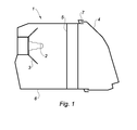
- the figure 1 allows to illustrate an optical module 1 according to the invention.
- Such an optical module having an optical axis and comprises a housing 6 inside which is located a light source 2 producing a light beam reflected by an optical reflector 3. The light beam is then projected onto a lens 4 which reverses it and the returns to the road in front of the vehicle in which the optical module is mounted.
- the lens 4 is disposed on a lens holder 7 secured to the housing 6.
- the light source is here a halogen lamp.
- a cut-off mechanism 5 is arranged between the reflector 3 and the lens 4. This cut-off mechanism 5 allows the light beam to be closed more or less in response to a command by the user of the vehicle or to an automatic command, in order to to propose different modes of lighting of the road.
- the cutoff mechanism 5 comprises a cutoff bar 10 according to the invention.
- This is a bi-function breaking mechanism, that is to say that the bar can be positioned in two positions, a first position in which it partially closes the light beam and corresponding to the code lights and a second position in which it does not close the light beam and corresponding to the high beam. In its first position, the cutoff bar 10 extends in a substantially vertical plane while in its second position it extends in a substantially horizontal plane.
- the cutoff bar 10 is positioned in front of the light source. It is mounted on a bar support 11 at a contact zone.
- the contact zone is the area of the bar in contact with the support bar 11, that is to say that the contact area is defined by a surface of the bar 10 in contact with the support 11 bar.
- the support 11 of bar comprises a first portion 12 having a gear 14 here with internal teeth, located at level of a first longitudinal end 72 of the bar 10 and a second portion 13 having a return spring 15 tending to return the bar 10 in the first position, that is to say in its substantially vertical position, the second part 13 being located at a second longitudinal end 73 of the bar 10.
- the first longitudinal end 72 is located to the left of the bar 10 while the second longitudinal end 73 is located to the right of the bar 10.
- the strip 10 is here made of stainless steel, that is to say a steel comprising alloys of iron, carbon and chromium, chromium representing more than 10.5% of the total mass of the bar 10.
- the bar comprises a central portion 71, located between the two longitudinal ends 72, 73.
- the central portion 71 is intended to be located in the path of the optical axis of the optical module.
- the bar 10 is of substantially rectangular shape and arranged to more or less close the light beam as explained above, that is to say to cut more or less the light beam.
- the strip 10 has a thickness of between 0.4 mm and 0.65 mm, in particular substantially equal to 0.6 mm. It has a height of between 10 and 25 mm and in particular a length equal to 80 mm.
- the thickness of the bar is measured along an axis perpendicular to the substantially rectangular shape defined by the bar. Its height is measured along an axis parallel to the small side of the substantially rectangular shape of the bar. Its length is measured along an axis perpendicular to its thickness and height, that is to say an axis defining the longitudinal extension of the bar.
- the contact zone is also located at a distance greater than 25 mm from the central part. It is understood here that the point of the contact zone closest to the central portion is located at a distance greater than 25 mm from the latter. The entire surface of the contact zone is thus located beyond 25 mm. This distance is measured along the axis defining the longitudinal extension of the bar, that is to say parallel to the large side of the substantially rectangular shape of the bar. It is thus the distance between the point of the zone of contact closest to the central portion and a plane passing through the central portion and extending perpendicular to the axis defining the longitudinal extension of the bar.
- the point of the contact zone closest to the central portion is in particular at a distance of less than 35 mm from the latter so that the assembly comprising the bar and its support has a reduced longitudinal size.
- the contact zone is here defined by two surfaces of the strip 10 receiving the support 11, located on either side of the central part, in particular at the longitudinal ends 72, 73 of the strip 10.
- each of the surfaces defining the contact area is located at a distance greater than 25 mm from the central part.
- the bar support 11 is not in contact with the bar 10 in an area of the bar between two planes perpendicular to the longitudinal extension of the bar, located at a distance of 25 mm from the central portion, on both sides of the latter.
- the thickness, the height and the distance of the contact zone from the central part are three parameters on which the invention acts, in conjunction with the conductivity of its material, to ensure that the contact zone heats too much so that its temperature remains below 220 ° C.
- the halogen lamp can heat the central portion 71 of the bar 10 to a temperature substantially equal to 450 ° C.
- the bar 10 dissipates this heat, particularly thanks to its high height and its reduced thickness, so that the temperature of its longitudinal ends 72, 73 at which is located here the contact zone, remains below substantially 220 ° C.
- the support 11 bar is thus made of plastics, resistant to temperatures substantially equal to 220 ° C, such as polyethylene sulfide.
- the support is for example overmolded on the bar, at the contact area.
- the spring 15 of the second portion 13 of the support 11 bar is however metal.
- the thermal conductivity of the stainless steel used for the bar of the invention is less than 35 W / (mK) (Watt per meter-Kelvin), especially 26 W / (mK) as opposed to standard steels whose conductivity is typically around 50 or even 60 W / (mK).
- the thermal conductivity of this alloy allows a good dissipation outside the bar and a limitation of the propagation of heat towards its longitudinal ends so that the temperature of the contact zone does not exceed 220 ° C as seen previously.
- the influence of the parameters of the bar is represented on the figure 4 .
- This figure illustrates the evolution of the temperature of the bar as a function of the distance of the central part in two different cases.
- the temperature at the central portion is 450 ° C and the ambient temperature of the bar is 130 ° C in both cases illustrated.
- the first curve that is to say the highest one, represents a case in which the strip has a thickness of 0.8 mm, is made of steel and has a thermal conductivity of 0.45 W / (mK). It is noted here that the temperature is 260 ° C to 25 mm from the central portion and 240 ° C to 30 mm from the central portion. It is therefore not possible to position a polyethylene sulphide support 25 mm from the central part because it could melt.
- the second curve represents an embodiment of the invention in which the strip is made of stainless steel, and has a thickness of 0.6 mm and a thermal conductivity of 26 W / (mK). It is noted here that the temperature is 205 ° C to 25 mm from the central portion and 190 ° C to 30 mm from the central portion. It is thus possible to position the polyethylene sulfide support on the contact zone located beyond 25 mm from the central part but also to position the point of the contact zone closest to the central part at a distance less than 30 mm from the central part.
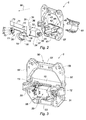
- the second portion 13 of the support 11 comprises a clamp 21 pinching the bar 10 from below and on either side thereof, that is to say that it clamps on a front face and on one side back of the bar 10 to support it.
- the clamp 21 thus clamps the bar at the contact zone.
- the clamp 21 of the second part 13 originates at an arm 22, which comprises the second part 13, extending parallel to a longitudinal axis of extension of the bar 10.
- At a distal end of the arm 22 to the right is an outgrowth 23 extending beyond the bar 10 to the right.
- the spring 15 is here wound around the arm 22 of the second part 13 and exerts a restoring force on the clamp 21 of the second part 13.
- the first portion 12 of the support 11 bar 10 comprises a central body 16 of substantially parallelepipedal shape which is born a clamp 17 pinching the bar 10 from below to support it.
- the gripper 17 of the first part 12 is similar to the gripper of the second part 13, that is to say that it clips the bar 10 on a front face and on a rear face thereof.
- the clamp 17 thus clamps the bar at the contact zone.
- the first portion 12 of the support 11 also comprises an outgrowth 18, protruding from the central body 16, to the left and extending beyond the bar 10 to the left.
- the first arm 19 extends in a common plane with the bar 10, perpendicular to the direction of longitudinal extension of the bar 10.
- the second arm 19 arm 20 extends in a direction perpendicular to the plane in which the strip 10 extends, that is to say perpendicularly to the first arm 19.
- the gear 14 internally toothing links the first arm 19 to the second arm 20 and is substantially circular in shape so that it forms between the first and the second arm 19, 20, a quarter circle.
- the bar support 11 is mounted on a frame 50 of substantially rectangular shape so that it has four connected branches, said upper branch 51, left branch 52, lower branch 53 and straight branch 54.
- a groove 55 of flared shape forward and having an opening 56 at a rear end, arranged to receive the protrusion 23 of the second support part 13.
- the protrusion 23 of the second portion 13 of the bar support 11 is thus inserted into the groove 55 from the front to the rear until it enters the opening 56.
- a groove 57 similar in shape to the groove of the left arm 54, that is to say of flared shape towards the front and having an opening (not visible ) at a rear end, arranged to receive the protrusion 18 of the first support portion 12.
- the armature 50 further comprises bores 58 distributed over its branches 51, 52, 53, 54 and arranged to mount the cut-off mechanism 5 in the optical module.
- the gear 14 with internal teeth of the first part 12 is driven by a pinion 31 of a DC motor 30.
- the gear ratio between the pinion 31 of the motor 30 and the gear 14 is 1/3 here. .
- the motor 30 is of substantially parallelepipedal shape so that it comprises an upper face 32, a rear face 33, a lower face 34, a front face 35, a right face 36 and a left face 37.
- the upper face 32 and the lower face 34, opposite each other are of curved shapes.
- connection zone 39 On the right of the motor 30, there is a connection zone 39 arranged to connect the motor 30 to a power source, for example a current source (not shown).
- the connection zone 39 thus defines the right face 36 of the motor 30 and a part of the upper, rear 33, lower 34 and front 35 faces situated to the right of the motor 30.
- the pinion 31 At the left face 37 of the motor 30 is the pinion 31. It is mounted on a drive shaft 38, protruding from the left face 37 of the motor 30 and located substantially in the middle of the left face 37 of the motor 30.
- the motor 30 is mounted on a motor support 40 located in the center and towards the rear of the armature 50, that is to say between the motor and the light source, once the breaking mechanism 5 has been mounted in the optical module.
- the support 40 of the motor comprises a lower wall 41 situated vis-à-vis the lower face 34 of the motor 30, a rear wall 42 or bottom, located vis-à-vis the rear face 33 of the motor 30, d a rear portion of the upper face 32 and a rear portion of the lower face 34 so that the motor 30 is in contact with the rear wall 42.
- the motor support 40 also comprises a U-shaped straight wall 43 , a central branch of the U being arranged vertically rearward and the two lateral branches of the U being substantially parallel to each other, horizontal and directed towards the front.
- the right wall 43 of the engine support 40 thus defines a notch within which a boss (not visible) of the connection zone 39, through which the motor connects to the power source, is inserted and solidifies with the motor support 40.
- the support 40 of the engine comprises a U-shaped left wall 44, a central branch of the U being arranged vertically rearward and the two lateral branches of the U being substantially parallel to each other, horizontal and directed towards the outside. 'before.
- the right wall 43 of the engine support 40 thus defines a notch within which the shaft 38 comprising the pinion 31 can be inserted, the pinion 31 then protruding beyond the support 40 of the motor 30 to the left.
- the cut-off mechanism 5 also comprises a heat shield 60 fitting an outer face of the rear wall 42 of the support 40 of the motor 30, that is to say a face facing rearwardly.
- the heat shield 60 is thus located between the engine support 40 and the light source. It is made of metal so that it protects the engine support 40 and the engine 30 from the heat released by the light source.
Landscapes
- Engineering & Computer Science (AREA)
- General Engineering & Computer Science (AREA)
- Non-Portable Lighting Devices Or Systems Thereof (AREA)
Applications Claiming Priority (1)
| Application Number | Priority Date | Filing Date | Title |
|---|---|---|---|
| FR1250865A FR2986197B1 (fr) | 2012-01-30 | 2012-01-30 | Barrette de coupure de faisceau lumineux pour module optique et le module optique |
Publications (2)
| Publication Number | Publication Date |
|---|---|
| EP2644972A1 true EP2644972A1 (de) | 2013-10-02 |
| EP2644972B1 EP2644972B1 (de) | 2018-10-10 |
Family
ID=47594590
Family Applications (1)
| Application Number | Title | Priority Date | Filing Date |
|---|---|---|---|
| EP13152946.3A Not-in-force EP2644972B1 (de) | 2012-01-30 | 2013-01-29 | Unterbrechungsleiste eines Lichtstrahls für optisches Modul, und entsprechendes optisches Modul |
Country Status (3)
| Country | Link |
|---|---|
| EP (1) | EP2644972B1 (de) |
| CN (1) | CN103225786B (de) |
| FR (1) | FR2986197B1 (de) |
Cited By (1)
| Publication number | Priority date | Publication date | Assignee | Title |
|---|---|---|---|---|
| EP2527726A3 (de) * | 2011-05-25 | 2018-04-04 | AML Systems | Unterbrechungsleiste für Lichtstrahl einer Lichtquelle |
Families Citing this family (1)
| Publication number | Priority date | Publication date | Assignee | Title |
|---|---|---|---|---|
| FR3046834B1 (fr) * | 2016-01-20 | 2020-07-03 | Aml Systems | Mecanisme de coupure pour projecteur de vehicule automobile, a barrette de coupure amovible. |
Citations (7)
| Publication number | Priority date | Publication date | Assignee | Title |
|---|---|---|---|---|
| DE20120417U1 (de) * | 2001-12-18 | 2002-03-21 | Automotive Lighting Reutlingen GmbH, 72762 Reutlingen | Strahlenblende für Kfz-Scheinwerfer |
| DE10217785C1 (de) * | 2002-04-21 | 2003-10-16 | Matthias Brand | Lichtverteilungsbaugruppe mit einer verstellbaren Blendenanordnung |
| DE102004033737A1 (de) * | 2004-07-13 | 2006-02-16 | Adam Opel Ag | Scheinwerfer mit einer drehbaren Blendenwelle |
| EP1726875A1 (de) * | 2005-05-27 | 2006-11-29 | Valeo Vision | Optisches Modul für Fahrzeug -Beleuchtungseinrichtung |
| DE102008001094A1 (de) * | 2007-05-21 | 2008-11-27 | Zizala Lichtsysteme Gmbh | Blendenanordnung für eine Lichteinheit bzw. einen Scheinwerfer eines Kraftfahrzeugs |
| US20090279318A1 (en) * | 2008-01-02 | 2009-11-12 | T.Y.C. Brother Industrial Co., Ltd. | Vehicle headlight assembly |
| EP2527726A2 (de) * | 2011-05-25 | 2012-11-28 | AML Systems | Unterbrechungsleiste für Lichtstrahl einer Lichtquelle |
Family Cites Families (2)
| Publication number | Priority date | Publication date | Assignee | Title |
|---|---|---|---|---|
| FR2827945B1 (fr) * | 2001-07-26 | 2004-02-27 | Valeo Vision | Projecteur elliptique equipe de caches a axes de pivotement transversaux pour vehicule automobile |
| US7736037B2 (en) * | 2006-06-02 | 2010-06-15 | Visteon Global Technologies, Inc. | Bi-functional lighting mechanism based on rotary actuator |
-
2012
- 2012-01-30 FR FR1250865A patent/FR2986197B1/fr not_active Expired - Fee Related
-
2013
- 2013-01-29 EP EP13152946.3A patent/EP2644972B1/de not_active Not-in-force
- 2013-01-30 CN CN201310088235.6A patent/CN103225786B/zh not_active Expired - Fee Related
Patent Citations (7)
| Publication number | Priority date | Publication date | Assignee | Title |
|---|---|---|---|---|
| DE20120417U1 (de) * | 2001-12-18 | 2002-03-21 | Automotive Lighting Reutlingen GmbH, 72762 Reutlingen | Strahlenblende für Kfz-Scheinwerfer |
| DE10217785C1 (de) * | 2002-04-21 | 2003-10-16 | Matthias Brand | Lichtverteilungsbaugruppe mit einer verstellbaren Blendenanordnung |
| DE102004033737A1 (de) * | 2004-07-13 | 2006-02-16 | Adam Opel Ag | Scheinwerfer mit einer drehbaren Blendenwelle |
| EP1726875A1 (de) * | 2005-05-27 | 2006-11-29 | Valeo Vision | Optisches Modul für Fahrzeug -Beleuchtungseinrichtung |
| DE102008001094A1 (de) * | 2007-05-21 | 2008-11-27 | Zizala Lichtsysteme Gmbh | Blendenanordnung für eine Lichteinheit bzw. einen Scheinwerfer eines Kraftfahrzeugs |
| US20090279318A1 (en) * | 2008-01-02 | 2009-11-12 | T.Y.C. Brother Industrial Co., Ltd. | Vehicle headlight assembly |
| EP2527726A2 (de) * | 2011-05-25 | 2012-11-28 | AML Systems | Unterbrechungsleiste für Lichtstrahl einer Lichtquelle |
Cited By (1)
| Publication number | Priority date | Publication date | Assignee | Title |
|---|---|---|---|---|
| EP2527726A3 (de) * | 2011-05-25 | 2018-04-04 | AML Systems | Unterbrechungsleiste für Lichtstrahl einer Lichtquelle |
Also Published As
| Publication number | Publication date |
|---|---|
| FR2986197B1 (fr) | 2015-01-23 |
| FR2986197A1 (fr) | 2013-08-02 |
| CN103225786A (zh) | 2013-07-31 |
| EP2644972B1 (de) | 2018-10-10 |
| CN103225786B (zh) | 2018-05-25 |
Similar Documents
| Publication | Publication Date | Title |
|---|---|---|
| EP2644973B1 (de) | Abblendlichtmechanismus für ein optisches Modul, und optisches Modul, das einen solchen Mechanismus umfasst | |
| EP2875282B1 (de) | Lichtstrahlemittierende vorrichtung und scheinwerfer, insbesondere für ein kraftfahrzeug, mit dieser vorrichtung | |
| CA2810385C (fr) | Module optique de dispositif d'eclairage et/ou de signalisation d'un vehicule automobile | |
| EP2574503A1 (de) | Scheinwerfermodul eines Kraftfahrzeugs mit Bajonettverschluss, Halterung und entsprechender Scheinwerfer | |
| EP2620325B1 (de) | Optisches Modul | |
| EP3822538B1 (de) | Optisches modul einer beleuchtungs- und/oder signalisierungvorrichtung eines kraftfahrzeugs | |
| EP2966342A1 (de) | Beleuchtungsmodul für kfz-projektionssheinwerfer mit positioniermittel zwischen kühlkörper und reflektor/linse | |
| EP0690261B1 (de) | Scheinwerfer mit elliptischem Reflektor und drehbarer Blende | |
| EP2966343A1 (de) | Beleuchtungsmodul für autoscheinwerfer mit positioniermittel zwischen kühlkörper und reflektor/leiterplatte | |
| EP2644972B1 (de) | Unterbrechungsleiste eines Lichtstrahls für optisches Modul, und entsprechendes optisches Modul | |
| EP3196541B1 (de) | Trennmechanismus für scheinwerfer eines kraftfahrzeugs, der durch einen elektromagneten mit zwei luftspalten betätigt wird | |
| EP1455133A1 (de) | Kfz-Scheinwerfer mit einer verstellbaren Blende, die mit Verriegelungsmitteln ausgerüstet ist | |
| FR2796448A1 (fr) | Projecteur pour vehicule automobile avec un cache a multipositions | |
| FR2796449A1 (fr) | Projecteur pour vehicule automobile avec un cache a multipositions | |
| WO2022269006A1 (fr) | Dispositif lumineux pour vehicule automobile avec une lentille de projection commune pour deux ensembles optiques | |
| EP2527726B1 (de) | Unterbrechungsleiste für Lichtstrahl einer Lichtquelle | |
| EP3196542B1 (de) | Abschirmmechanismus für scheinwerfer eines kraftfahrzeugs mit herausnehmbarer blendenleiste | |
| FR2796447A1 (fr) | Projecteur pour vehicule automobile avec un double cache mobile | |
| EP0982535B1 (de) | Kraftfahrzeugscheinwerfer mit elliptischem Reflektor und mit einer schwenkbaren Blende | |
| EP2551153A1 (de) | Halterungssystemeinheit für ein optisches Modul und eine Anschlussvorrichtung, die ein Regulierungsmittel für die Position der Halterung aufnehmen kann | |
| FR3064721A1 (fr) | Dispositif lumineux avec radiateur traversant le boitier | |
| EP3030831B1 (de) | Kfz-projektionsscheinwerfer mit einer beweglichen blende | |
| EP2966340A1 (de) | Beleuchtungsmodul für kfz-scheinwerfer mit positionierung zwischen blende und kühlkörper | |
| WO2020089118A1 (fr) | Dispositif lumineux d'un véhicule automobile | |
| FR2781870A1 (fr) | Projecteur du type elliptique, comportant un cache basculant |
Legal Events
| Date | Code | Title | Description |
|---|---|---|---|
| PUAI | Public reference made under article 153(3) epc to a published international application that has entered the european phase |
Free format text: ORIGINAL CODE: 0009012 |
|
| AK | Designated contracting states |
Kind code of ref document: A1 Designated state(s): AL AT BE BG CH CY CZ DE DK EE ES FI FR GB GR HR HU IE IS IT LI LT LU LV MC MK MT NL NO PL PT RO RS SE SI SK SM TR |
|
| AX | Request for extension of the european patent |
Extension state: BA ME |
|
| 17P | Request for examination filed |
Effective date: 20140402 |
|
| RBV | Designated contracting states (corrected) |
Designated state(s): AL AT BE BG CH CY CZ DE DK EE ES FI FR GB GR HR HU IE IS IT LI LT LU LV MC MK MT NL NO PL PT RO RS SE SI SK SM TR |
|
| REG | Reference to a national code |
Ref country code: DE Ref legal event code: R079 Ref document number: 602013044710 Country of ref document: DE Free format text: PREVIOUS MAIN CLASS: F21S0008120000 Ipc: F21V0029000000 |
|
| RIC1 | Information provided on ipc code assigned before grant |
Ipc: F21S 41/17 20180101ALI20180417BHEP Ipc: F21S 41/689 20180101ALI20180417BHEP Ipc: F21S 41/40 20180101ALI20180417BHEP Ipc: F21V 11/16 20060101ALI20180417BHEP Ipc: F21V 29/00 20060101AFI20180417BHEP Ipc: F21S 45/10 20180101ALI20180417BHEP |
|
| GRAP | Despatch of communication of intention to grant a patent |
Free format text: ORIGINAL CODE: EPIDOSNIGR1 |
|
| STAA | Information on the status of an ep patent application or granted ep patent |
Free format text: STATUS: GRANT OF PATENT IS INTENDED |
|
| INTG | Intention to grant announced |
Effective date: 20180608 |
|
| GRAS | Grant fee paid |
Free format text: ORIGINAL CODE: EPIDOSNIGR3 |
|
| GRAA | (expected) grant |
Free format text: ORIGINAL CODE: 0009210 |
|
| STAA | Information on the status of an ep patent application or granted ep patent |
Free format text: STATUS: THE PATENT HAS BEEN GRANTED |
|
| AK | Designated contracting states |
Kind code of ref document: B1 Designated state(s): AL AT BE BG CH CY CZ DE DK EE ES FI FR GB GR HR HU IE IS IT LI LT LU LV MC MK MT NL NO PL PT RO RS SE SI SK SM TR |
|
| REG | Reference to a national code |
Ref country code: GB Ref legal event code: FG4D Free format text: NOT ENGLISH |
|
| REG | Reference to a national code |
Ref country code: CH Ref legal event code: EP Ref country code: AT Ref legal event code: REF Ref document number: 1051671 Country of ref document: AT Kind code of ref document: T Effective date: 20181015 |
|
| REG | Reference to a national code |
Ref country code: IE Ref legal event code: FG4D Free format text: LANGUAGE OF EP DOCUMENT: FRENCH |
|
| REG | Reference to a national code |
Ref country code: DE Ref legal event code: R096 Ref document number: 602013044710 Country of ref document: DE |
|
| REG | Reference to a national code |
Ref country code: NL Ref legal event code: MP Effective date: 20181010 |
|
| REG | Reference to a national code |
Ref country code: LT Ref legal event code: MG4D |
|
| REG | Reference to a national code |
Ref country code: AT Ref legal event code: MK05 Ref document number: 1051671 Country of ref document: AT Kind code of ref document: T Effective date: 20181010 |
|
| PG25 | Lapsed in a contracting state [announced via postgrant information from national office to epo] |
Ref country code: NL Free format text: LAPSE BECAUSE OF FAILURE TO SUBMIT A TRANSLATION OF THE DESCRIPTION OR TO PAY THE FEE WITHIN THE PRESCRIBED TIME-LIMIT Effective date: 20181010 |
|
| PG25 | Lapsed in a contracting state [announced via postgrant information from national office to epo] |
Ref country code: ES Free format text: LAPSE BECAUSE OF FAILURE TO SUBMIT A TRANSLATION OF THE DESCRIPTION OR TO PAY THE FEE WITHIN THE PRESCRIBED TIME-LIMIT Effective date: 20181010 Ref country code: LV Free format text: LAPSE BECAUSE OF FAILURE TO SUBMIT A TRANSLATION OF THE DESCRIPTION OR TO PAY THE FEE WITHIN THE PRESCRIBED TIME-LIMIT Effective date: 20181010 Ref country code: HR Free format text: LAPSE BECAUSE OF FAILURE TO SUBMIT A TRANSLATION OF THE DESCRIPTION OR TO PAY THE FEE WITHIN THE PRESCRIBED TIME-LIMIT Effective date: 20181010 Ref country code: BG Free format text: LAPSE BECAUSE OF FAILURE TO SUBMIT A TRANSLATION OF THE DESCRIPTION OR TO PAY THE FEE WITHIN THE PRESCRIBED TIME-LIMIT Effective date: 20190110 Ref country code: NO Free format text: LAPSE BECAUSE OF FAILURE TO SUBMIT A TRANSLATION OF THE DESCRIPTION OR TO PAY THE FEE WITHIN THE PRESCRIBED TIME-LIMIT Effective date: 20190110 Ref country code: PL Free format text: LAPSE BECAUSE OF FAILURE TO SUBMIT A TRANSLATION OF THE DESCRIPTION OR TO PAY THE FEE WITHIN THE PRESCRIBED TIME-LIMIT Effective date: 20181010 Ref country code: FI Free format text: LAPSE BECAUSE OF FAILURE TO SUBMIT A TRANSLATION OF THE DESCRIPTION OR TO PAY THE FEE WITHIN THE PRESCRIBED TIME-LIMIT Effective date: 20181010 Ref country code: LT Free format text: LAPSE BECAUSE OF FAILURE TO SUBMIT A TRANSLATION OF THE DESCRIPTION OR TO PAY THE FEE WITHIN THE PRESCRIBED TIME-LIMIT Effective date: 20181010 Ref country code: AT Free format text: LAPSE BECAUSE OF FAILURE TO SUBMIT A TRANSLATION OF THE DESCRIPTION OR TO PAY THE FEE WITHIN THE PRESCRIBED TIME-LIMIT Effective date: 20181010 Ref country code: IS Free format text: LAPSE BECAUSE OF FAILURE TO SUBMIT A TRANSLATION OF THE DESCRIPTION OR TO PAY THE FEE WITHIN THE PRESCRIBED TIME-LIMIT Effective date: 20190210 |
|
| PG25 | Lapsed in a contracting state [announced via postgrant information from national office to epo] |
Ref country code: SE Free format text: LAPSE BECAUSE OF FAILURE TO SUBMIT A TRANSLATION OF THE DESCRIPTION OR TO PAY THE FEE WITHIN THE PRESCRIBED TIME-LIMIT Effective date: 20181010 Ref country code: RS Free format text: LAPSE BECAUSE OF FAILURE TO SUBMIT A TRANSLATION OF THE DESCRIPTION OR TO PAY THE FEE WITHIN THE PRESCRIBED TIME-LIMIT Effective date: 20181010 Ref country code: PT Free format text: LAPSE BECAUSE OF FAILURE TO SUBMIT A TRANSLATION OF THE DESCRIPTION OR TO PAY THE FEE WITHIN THE PRESCRIBED TIME-LIMIT Effective date: 20190210 Ref country code: GR Free format text: LAPSE BECAUSE OF FAILURE TO SUBMIT A TRANSLATION OF THE DESCRIPTION OR TO PAY THE FEE WITHIN THE PRESCRIBED TIME-LIMIT Effective date: 20190111 Ref country code: AL Free format text: LAPSE BECAUSE OF FAILURE TO SUBMIT A TRANSLATION OF THE DESCRIPTION OR TO PAY THE FEE WITHIN THE PRESCRIBED TIME-LIMIT Effective date: 20181010 |
|
| REG | Reference to a national code |
Ref country code: DE Ref legal event code: R097 Ref document number: 602013044710 Country of ref document: DE |
|
| PG25 | Lapsed in a contracting state [announced via postgrant information from national office to epo] |
Ref country code: DK Free format text: LAPSE BECAUSE OF FAILURE TO SUBMIT A TRANSLATION OF THE DESCRIPTION OR TO PAY THE FEE WITHIN THE PRESCRIBED TIME-LIMIT Effective date: 20181010 Ref country code: CZ Free format text: LAPSE BECAUSE OF FAILURE TO SUBMIT A TRANSLATION OF THE DESCRIPTION OR TO PAY THE FEE WITHIN THE PRESCRIBED TIME-LIMIT Effective date: 20181010 Ref country code: IT Free format text: LAPSE BECAUSE OF FAILURE TO SUBMIT A TRANSLATION OF THE DESCRIPTION OR TO PAY THE FEE WITHIN THE PRESCRIBED TIME-LIMIT Effective date: 20181010 |
|
| PLBE | No opposition filed within time limit |
Free format text: ORIGINAL CODE: 0009261 |
|
| STAA | Information on the status of an ep patent application or granted ep patent |
Free format text: STATUS: NO OPPOSITION FILED WITHIN TIME LIMIT |
|
| PG25 | Lapsed in a contracting state [announced via postgrant information from national office to epo] |
Ref country code: SM Free format text: LAPSE BECAUSE OF FAILURE TO SUBMIT A TRANSLATION OF THE DESCRIPTION OR TO PAY THE FEE WITHIN THE PRESCRIBED TIME-LIMIT Effective date: 20181010 Ref country code: SK Free format text: LAPSE BECAUSE OF FAILURE TO SUBMIT A TRANSLATION OF THE DESCRIPTION OR TO PAY THE FEE WITHIN THE PRESCRIBED TIME-LIMIT Effective date: 20181010 Ref country code: MC Free format text: LAPSE BECAUSE OF FAILURE TO SUBMIT A TRANSLATION OF THE DESCRIPTION OR TO PAY THE FEE WITHIN THE PRESCRIBED TIME-LIMIT Effective date: 20181010 Ref country code: EE Free format text: LAPSE BECAUSE OF FAILURE TO SUBMIT A TRANSLATION OF THE DESCRIPTION OR TO PAY THE FEE WITHIN THE PRESCRIBED TIME-LIMIT Effective date: 20181010 Ref country code: RO Free format text: LAPSE BECAUSE OF FAILURE TO SUBMIT A TRANSLATION OF THE DESCRIPTION OR TO PAY THE FEE WITHIN THE PRESCRIBED TIME-LIMIT Effective date: 20181010 |
|
| REG | Reference to a national code |
Ref country code: CH Ref legal event code: PL |
|
| 26N | No opposition filed |
Effective date: 20190711 |
|
| PG25 | Lapsed in a contracting state [announced via postgrant information from national office to epo] |
Ref country code: LU Free format text: LAPSE BECAUSE OF NON-PAYMENT OF DUE FEES Effective date: 20190129 |
|
| REG | Reference to a national code |
Ref country code: BE Ref legal event code: MM Effective date: 20190131 |
|
| REG | Reference to a national code |
Ref country code: IE Ref legal event code: MM4A |
|
| PG25 | Lapsed in a contracting state [announced via postgrant information from national office to epo] |
Ref country code: SI Free format text: LAPSE BECAUSE OF FAILURE TO SUBMIT A TRANSLATION OF THE DESCRIPTION OR TO PAY THE FEE WITHIN THE PRESCRIBED TIME-LIMIT Effective date: 20181010 |
|
| PG25 | Lapsed in a contracting state [announced via postgrant information from national office to epo] |
Ref country code: BE Free format text: LAPSE BECAUSE OF NON-PAYMENT OF DUE FEES Effective date: 20190131 |
|
| PG25 | Lapsed in a contracting state [announced via postgrant information from national office to epo] |
Ref country code: LI Free format text: LAPSE BECAUSE OF NON-PAYMENT OF DUE FEES Effective date: 20190131 Ref country code: CH Free format text: LAPSE BECAUSE OF NON-PAYMENT OF DUE FEES Effective date: 20190131 |
|
| PG25 | Lapsed in a contracting state [announced via postgrant information from national office to epo] |
Ref country code: IE Free format text: LAPSE BECAUSE OF NON-PAYMENT OF DUE FEES Effective date: 20190129 |
|
| PG25 | Lapsed in a contracting state [announced via postgrant information from national office to epo] |
Ref country code: TR Free format text: LAPSE BECAUSE OF FAILURE TO SUBMIT A TRANSLATION OF THE DESCRIPTION OR TO PAY THE FEE WITHIN THE PRESCRIBED TIME-LIMIT Effective date: 20181010 |
|
| PG25 | Lapsed in a contracting state [announced via postgrant information from national office to epo] |
Ref country code: MT Free format text: LAPSE BECAUSE OF FAILURE TO SUBMIT A TRANSLATION OF THE DESCRIPTION OR TO PAY THE FEE WITHIN THE PRESCRIBED TIME-LIMIT Effective date: 20181010 |
|
| PG25 | Lapsed in a contracting state [announced via postgrant information from national office to epo] |
Ref country code: CY Free format text: LAPSE BECAUSE OF FAILURE TO SUBMIT A TRANSLATION OF THE DESCRIPTION OR TO PAY THE FEE WITHIN THE PRESCRIBED TIME-LIMIT Effective date: 20181010 |
|
| PG25 | Lapsed in a contracting state [announced via postgrant information from national office to epo] |
Ref country code: HU Free format text: LAPSE BECAUSE OF FAILURE TO SUBMIT A TRANSLATION OF THE DESCRIPTION OR TO PAY THE FEE WITHIN THE PRESCRIBED TIME-LIMIT; INVALID AB INITIO Effective date: 20130129 |
|
| PG25 | Lapsed in a contracting state [announced via postgrant information from national office to epo] |
Ref country code: MK Free format text: LAPSE BECAUSE OF FAILURE TO SUBMIT A TRANSLATION OF THE DESCRIPTION OR TO PAY THE FEE WITHIN THE PRESCRIBED TIME-LIMIT Effective date: 20181010 |
|
| REG | Reference to a national code |
Ref country code: GB Ref legal event code: 746 Effective date: 20230607 |
|
| REG | Reference to a national code |
Ref country code: DE Ref legal event code: R084 Ref document number: 602013044710 Country of ref document: DE |
|
| P01 | Opt-out of the competence of the unified patent court (upc) registered |
Effective date: 20230628 |
|
| PGFP | Annual fee paid to national office [announced via postgrant information from national office to epo] |
Ref country code: DE Payment date: 20240129 Year of fee payment: 12 Ref country code: GB Payment date: 20240123 Year of fee payment: 12 |
|
| PGFP | Annual fee paid to national office [announced via postgrant information from national office to epo] |
Ref country code: FR Payment date: 20240125 Year of fee payment: 12 |
|
| REG | Reference to a national code |
Ref country code: DE Ref legal event code: R119 Ref document number: 602013044710 Country of ref document: DE |
|
| GBPC | Gb: european patent ceased through non-payment of renewal fee |
Effective date: 20250129 |
|
| PG25 | Lapsed in a contracting state [announced via postgrant information from national office to epo] |
Ref country code: DE Free format text: LAPSE BECAUSE OF NON-PAYMENT OF DUE FEES Effective date: 20250801 |
|
| PG25 | Lapsed in a contracting state [announced via postgrant information from national office to epo] |
Ref country code: GB Free format text: LAPSE BECAUSE OF NON-PAYMENT OF DUE FEES Effective date: 20250129 |
|
| PG25 | Lapsed in a contracting state [announced via postgrant information from national office to epo] |
Ref country code: FR Free format text: LAPSE BECAUSE OF NON-PAYMENT OF DUE FEES Effective date: 20250131 |