EP2646691B1 - Pompe à roue à aubes - Google Patents
Pompe à roue à aubes Download PDFInfo
- Publication number
- EP2646691B1 EP2646691B1 EP11793400.0A EP11793400A EP2646691B1 EP 2646691 B1 EP2646691 B1 EP 2646691B1 EP 11793400 A EP11793400 A EP 11793400A EP 2646691 B1 EP2646691 B1 EP 2646691B1
- Authority
- EP
- European Patent Office
- Prior art keywords
- impeller
- housing
- ellipse
- pump according
- impeller pump
- Prior art date
- Legal status (The legal status is an assumption and is not a legal conclusion. Google has not performed a legal analysis and makes no representation as to the accuracy of the status listed.)
- Active
Links
Images

Classifications
-
- F—MECHANICAL ENGINEERING; LIGHTING; HEATING; WEAPONS; BLASTING
- F04—POSITIVE - DISPLACEMENT MACHINES FOR LIQUIDS; PUMPS FOR LIQUIDS OR ELASTIC FLUIDS
- F04C—ROTARY-PISTON, OR OSCILLATING-PISTON, POSITIVE-DISPLACEMENT MACHINES FOR LIQUIDS; ROTARY-PISTON, OR OSCILLATING-PISTON, POSITIVE-DISPLACEMENT PUMPS
- F04C5/00—Rotary-piston machines or pumps with the working-chamber walls at least partly resiliently deformable
-
- F—MECHANICAL ENGINEERING; LIGHTING; HEATING; WEAPONS; BLASTING
- F04—POSITIVE - DISPLACEMENT MACHINES FOR LIQUIDS; PUMPS FOR LIQUIDS OR ELASTIC FLUIDS
- F04C—ROTARY-PISTON, OR OSCILLATING-PISTON, POSITIVE-DISPLACEMENT MACHINES FOR LIQUIDS; ROTARY-PISTON, OR OSCILLATING-PISTON, POSITIVE-DISPLACEMENT PUMPS
- F04C15/00—Component parts, details or accessories of machines, pumps or pumping installations, not provided for in groups F04C2/00 - F04C14/00
- F04C15/06—Arrangements for admission or discharge of the working fluid, e.g. constructional features of the inlet or outlet
-
- F—MECHANICAL ENGINEERING; LIGHTING; HEATING; WEAPONS; BLASTING
- F04—POSITIVE - DISPLACEMENT MACHINES FOR LIQUIDS; PUMPS FOR LIQUIDS OR ELASTIC FLUIDS
- F04C—ROTARY-PISTON, OR OSCILLATING-PISTON, POSITIVE-DISPLACEMENT MACHINES FOR LIQUIDS; ROTARY-PISTON, OR OSCILLATING-PISTON, POSITIVE-DISPLACEMENT PUMPS
- F04C2/00—Rotary-piston machines or pumps
- F04C2/30—Rotary-piston machines or pumps having the characteristics covered by two or more groups F04C2/02, F04C2/08, F04C2/22, F04C2/24 or having the characteristics covered by one of these groups together with some other type of movement between co-operating members
- F04C2/34—Rotary-piston machines or pumps having the characteristics covered by two or more groups F04C2/02, F04C2/08, F04C2/22, F04C2/24 or having the characteristics covered by one of these groups together with some other type of movement between co-operating members having the movement defined in groups F04C2/08 or F04C2/22 and relative reciprocation between the co-operating members
-
- F—MECHANICAL ENGINEERING; LIGHTING; HEATING; WEAPONS; BLASTING
- F04—POSITIVE - DISPLACEMENT MACHINES FOR LIQUIDS; PUMPS FOR LIQUIDS OR ELASTIC FLUIDS
- F04C—ROTARY-PISTON, OR OSCILLATING-PISTON, POSITIVE-DISPLACEMENT MACHINES FOR LIQUIDS; ROTARY-PISTON, OR OSCILLATING-PISTON, POSITIVE-DISPLACEMENT PUMPS
- F04C2250/00—Geometry
- F04C2250/10—Geometry of the inlet or outlet
Definitions
- the invention relates to an impeller pump with improved geometry of the inlet and outlet openings.
- Impeller pumps use an impeller wheel with a plurality of flexible impeller blades (also called impeller blades) that rotate in a pump housing.
- the diameter of the impeller wheel i. the length of the impeller blades is chosen so that the free end of the impeller blades rests in any position of the impeller on the inner wall of the pump housing.
- the distance of the inner wall from the axis of rotation of the impeller decreases.
- the impeller blades are bent (stronger) during the movement from the drain opening to the inlet opening than when moving from the inlet opening to the drain opening.
- the volume, which is conveyed during a rotation of the impeller from the drain opening to the inlet opening smaller than the volume which is conveyed during a rotation of the impeller from the inlet opening to the drain opening. This results in a promotion of the medium to be pumped from the inlet opening to the drain opening.
- Impeller pumps are particularly suitable for pumping contaminated (eg with food waste) liquids. Furthermore, it is advantageous that impeller pumps are self-priming due to the sealing of the impeller blades relative to the pump housing.
- impeller blades Since the impeller blades to ensure this seal, firmly abut the inner wall of the pump housing, they are subject to heavy wear. This is reinforced by the fact that the impeller blades, when they sweep the inlet opening and the drain opening, are pressed both by their elasticity and by centrifugal forces in these openings and especially against their edges.
- An impeller pump comprises a housing having an inlet and a drain, each at an inlet opening and a drain opening in the housing interior of the impeller pump, in which an impeller is with a plurality of elastic impeller blades (for example made of rubber), go over ,
- the shape of the inlet and / or the drain opening is designed so that the cross section of the inlet and / or the drain on the inside facing the housing has the shape of an ellipse.
- cross section should be understood to mean that the inlet or the outlet from the interior of the housing is viewed along an axis defined by the inlet or outlet. This means, for example, that an inlet, which is given by a round tube, has a circular cross-section, even if the actual shape of the inlet opening in the housing is no longer circular if it is unwound on a plane.
- the ratio of the length of the minor axis of the ellipse to the width of the impeller blades is less than 1: 1, preferably less than or equal to 1: 2, more preferably about 1: 3 or about 1: 4. Characterized in that the width of the inlet or outlet opening (corresponding to the minor axis of the ellipse) is smaller than the width of the impeller blades, the load on the impeller blades is reduced by deformation when they are moved over the inlet or outlet opening.
- the ratio of the length of the minor axis of the ellipse to the length of the major axis of the ellipse is less than or equal to 1: 2, preferably about 1: 3 or about 1: 4.
- the ellipse is aligned so that the main axis extends along the direction of movement of the impeller blades.
- the cross section of the inlet and / or the drain on the side facing away from the housing interior substantially in the shape of a circle.
- the area of the ellipse and the area of the circle respectively of the inlet and the outlet differ essentially by less than 10%, more preferably they are substantially the same size.
- the housing of the impeller pump consists of at least two parts, which can be assembled substantially along a dividing plane.
- the contact surfaces of the two parts may differ slightly from the dividing plane, for example, to form projections in one part and corresponding recesses in the other part, which facilitate the assembly of the two parts.
- the two parts of the housing are axially symmetrical about an axis of rotation lying substantially in the plane of division, i. a rotation of a housing part by 180 ° about this axis of rotation results in the second housing part.
- the dividing plane along which the two parts are composable includes the major axis of the above-mentioned ellipse, i. the dividing plane divides the inlet and the outlet including the associated inlet and outlet openings into substantially equal parts.
- the (at least) two-part form of the pump housing makes it possible to produce the parts of the pump housing, for example by an injection molding method or a similar method. This is particularly advantageous because by changing the shape of the inlet or outlet to the housing interior, the housing can not be made in one piece by milling or casting.
- the fin end of the impeller blades can be reinforced by a wire insert which absorbs the forces when the inlet or drain is overstretched and reduces deformations of the impeller fins.
- the transition of the inner wall of the housing from a region of maximum diameter to a region of reduced diameter substantially coincides with the minor axis of the ellipse.
- this transition is not sudden, but the distance of the housing inner wall from the axis of rotation of the impeller wheel is reduced continuously from the maximum distance at which the impeller blades are not bent or least, to the minimum distance at which the impeller blades are bent the strongest.
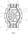
- the housing (1) of the impeller pump has an inlet (2) and a drain (3). Inside the housing (1) an impeller wheel (4) is rotatably mounted (in the direction of arrow) about an axis (A).
- the impeller wheel (4) has a plurality of impeller blades (5), the fin end (6) abutting against the inner wall (7) of the housing (1).
- the interior of the housing (1) is not rotationally symmetrical about the axis (A), but is shaped so that the impeller blades (5) during movement from the inlet opening (8) to the drain opening (9) are not (or only slightly) deformed while being bent in the movement from the drain opening (9) to the inlet opening (8) against the rotational direction of the impeller wheel (4).
- the volume between two impeller blades (5) in the movement from the inlet opening (8) to the drain opening (9) is greater than the volume during movement from the drain opening (9) to the inlet opening (8), whereby the medium to be pumped from the Inlet opening (8) is conveyed to the drain opening.
- FIG. 2 an impeller wheel (4) is shown, the impeller blades (5) are reinforced at its end (6) with a wire (10) to the deformation of the fin end (6) when sweeping the inlet opening (8) and the drain opening (9) minimize.
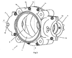
- Fig. 3 shows a perspective view of the housing of an impeller pump according to the invention.
- the housing (1) of the impeller pump is composed of two parts (1a, 1b), which are axisymmetrical with respect to the axis R, along a dividing plane (11). Projections (12) on a housing part (1b), which engage in corresponding recesses (13) on the other housing part (1a) and thereby facilitate the assembly of the two housing parts (1a, 1b), thereby ensuring a slight deviation of the contact surfaces between the two Divide (1a, 1b) from the division plane.
- the two housing parts (1a, 1b) are held together by a plurality of screw connections (14). Between the two housing parts (1a, 1b) sealing elements may be provided which can also take over the function of the projections (12) and recesses (13), for example, when a sealing element engages in a groove formed in both housing parts groove.
- the interior of the housing (1) of the impeller pump according to the invention from a range in which the distance between the inner wall (7) and the axis of rotation of the impeller (4) is maximum (movement of the impeller blades (5) of the inlet opening ( 8) to the drain opening (9)), and an area where this distance is reduced (movement of the impeller blades (5) from the drain opening (9) to the inlet opening (8)) to achieve deformation of the impeller blades (5).
- the (continuous) transition from the maximum distance region to the minimum distance region begins at the level of the semi-axis of the ellipse of the inlet opening (8) or the outlet opening (9), ie approximately in the middle of the inlet opening (8) or the outlet opening (8). 9) .
- the in Fig. 3 shown housing (1) is shown without side wall. Such can be produced separately from the two housing parts (1a, 1b) and connected to the corresponding housing part (1a), for example by means of screwing or gluing.
- the housing part can also be made equal with side wall.
- Clamping screws (15) on the inlet (2) and on the outlet (3) can be used to connect connection pipes to the inlet (2) or outlet (3) of the housing (1).
- Fig. 3 is also the elongated and narrow shape of the inlet opening (8) to recognize, which causes the impeller blades (5) of the in Fig. 3 Not shown Impeller wheel (4) by the centrifugal forces due to the rotation of the Impellerrades (4) and the elastic restoring forces due to the deformation of the impeller blades (5) are not pressed so much outwardly and deformed, as in the case of impeller pumps where the inlet opening over the entire width of the impeller blades and thus also of the housing interior extends.
- drain opening (9) is preferably formed equal to the inlet opening (8).
- the cross-section of the inlet opening (8) ie the view of the inlet opening (8) from inside the housing along the axis defined by the inlet (Z) has the shape of an ellipse.
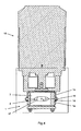
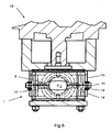
- Fig. 4 shows a section through an impeller pump according to the invention along a plane perpendicular to the axis defined by the inlet (Z).
- the section marked by B is in Fig. 5 shown again, with hidden edges are shown in dashed lines there.
- Fig. 4 shows an embodiment of the impeller pump according to the invention, in which the housing (1) with a drive unit (16) is connected, which drives the impeller (4) (not shown).
- the elliptical shape of the cross section of the inlet opening (8) can be clearly seen.
- the major axis of the ellipse, which runs in the dividing plane (11) between the two housing parts (1a, 1b), in this embodiment has about three times the length of the minor axis.
- the length of the Secondary axis is about one third of the width of the inner wall (7) of the housing, that is about one third of the width of the impeller blades (5).
- the inlet (2) and the outlet (3) at their outer, remote from the housing interior ends inside the shape of a circle to normal, round connection pipes with the inlet (2) and the Start-up (3) easy to connect.
Landscapes
- Engineering & Computer Science (AREA)
- Mechanical Engineering (AREA)
- General Engineering & Computer Science (AREA)
- Structures Of Non-Positive Displacement Pumps (AREA)
Claims (9)
- Pompe à impulseur flexible comprenant un carter (1) présentant une admission (2) et une sortie (3) et un impulseur (4) comprenant une pluralité d'aubes d'impulseur (5) élastique, caractérisé en ce que la section transversale de l'admission (2) et/ou de la sortie (3) présente la forme d'une ellipse sur le côté tourné vers l'intérieur du carter.
- Pompe à impulseur flexible selon la revendication 1, dans laquelle le rapport de la longueur de l'axe secondaire de l'ellipse à la largeur des aubes d'impulseur (5) est inférieur à 1:1, de préférence inférieur ou égal à 1:2, plus encore de préférence d'environ 1:3 ou d'environ 1:4.
- Pompe à impulseur flexible selon la revendication 1 ou 2, dans laquelle le rapport de la longueur de l'axe secondaire de l'ellipse à la longueur de l'axe principal de l'ellipse est inférieur ou égal à 1:2, est de préférence d'environ 1:3 ou d'environ 1:4.
- Pompe à impulseur flexible selon l'une des revendications précédentes, dans laquelle la section transversale de l'admission (2) et/ou de la sortie (3) a essentiellement la forme d'un cercle sur le côté éloigné de l'intérieur du carter.
- Pompe à impulseur flexible selon la revendication 4, dans laquelle la surface de l'ellipse et la surface du cercle associé se différencient essentiellement de moins de 10 %, sont de préférence essentiellement de la même dimension.
- Pompe à impulseur flexible selon l'une des revendications précédentes, dans laquelle le carter (1) est composé d'au moins deux parties (1 a, 1 b) qui peuvent essentiellement être mises ensemble le long d'un plan de division (11).
- Pompe à impulseur flexible selon la revendication 6, dans laquelle les deux parties (1 a, 1 b) du carter (1) sont en symétrie d'axe l'une par rapport à l'autre.
- Pompe à impulseur flexible selon l'une des revendications 6 ou 7, dans laquelle le plan de division (11) contient l'axe principal de l'ellipse.
- Pompe à impulseur flexible selon l'une des revendications précédentes, dans laquelle le passage de la paroi intérieure (7) du carter (1), d'une zone avec un diamètre maximal à une zone avec un diamètre réduit, coïncide essentiellement avec l'axe secondaire de l'ellipse.
Applications Claiming Priority (2)
| Application Number | Priority Date | Filing Date | Title |
|---|---|---|---|
| DE201010062298 DE102010062298B4 (de) | 2010-12-01 | 2010-12-01 | Impellerpumpe |
| PCT/EP2011/071525 WO2012072746A2 (fr) | 2010-12-01 | 2011-12-01 | Pompe à roue à aubes |
Publications (2)
| Publication Number | Publication Date |
|---|---|
| EP2646691A2 EP2646691A2 (fr) | 2013-10-09 |
| EP2646691B1 true EP2646691B1 (fr) | 2015-06-17 |
Family
ID=45217535
Family Applications (1)
| Application Number | Title | Priority Date | Filing Date |
|---|---|---|---|
| EP11793400.0A Active EP2646691B1 (fr) | 2010-12-01 | 2011-12-01 | Pompe à roue à aubes |
Country Status (4)
| Country | Link |
|---|---|
| EP (1) | EP2646691B1 (fr) |
| DE (1) | DE102010062298B4 (fr) |
| DK (1) | DK2646691T3 (fr) |
| WO (1) | WO2012072746A2 (fr) |
Cited By (1)
| Publication number | Priority date | Publication date | Assignee | Title |
|---|---|---|---|---|
| DE102017107643A1 (de) | 2017-04-10 | 2018-10-11 | Biotrans Ag | Impellerpumpe |
Families Citing this family (1)
| Publication number | Priority date | Publication date | Assignee | Title |
|---|---|---|---|---|
| US11339782B2 (en) | 2020-06-26 | 2022-05-24 | LeimbachCausey, LLC | Multi-chamber impeller pump |
Family Cites Families (8)
| Publication number | Priority date | Publication date | Assignee | Title |
|---|---|---|---|---|
| LU30267A1 (fr) * | 1949-08-19 | |||
| GB770113A (en) * | 1954-03-15 | 1957-03-13 | Herbert Josef Venediger | Improvements in rotary blowers or compressors |
| DE1236340B (de) * | 1956-07-20 | 1967-03-09 | Jabsco Pump Company | Rotierende Verdraengerpumpe |
| FR1478699A (fr) * | 1966-04-19 | 1967-04-28 | Aubages flexibles pour pompes rotatives | |
| US3806283A (en) * | 1973-01-04 | 1974-04-23 | Int Standard Electric Corp | Pump by-pass |
| FR2819294A1 (fr) * | 2000-12-13 | 2002-07-12 | Gerard Goffredi | Rotor/impulseur de pompe a palettes souples et interchangeables |
| US6394753B1 (en) * | 2001-02-07 | 2002-05-28 | Hypro Corporation | Flexible impeller removal and installation method |
| DE202006010360U1 (de) * | 2006-06-28 | 2006-09-21 | Elektron Berlin Gmbh | Impellerpumpe zum Fördern von Flüssigkeiten |
-
2010
- 2010-12-01 DE DE201010062298 patent/DE102010062298B4/de not_active Expired - Fee Related
-
2011
- 2011-12-01 DK DK11793400.0T patent/DK2646691T3/en active
- 2011-12-01 WO PCT/EP2011/071525 patent/WO2012072746A2/fr not_active Ceased
- 2011-12-01 EP EP11793400.0A patent/EP2646691B1/fr active Active
Cited By (2)
| Publication number | Priority date | Publication date | Assignee | Title |
|---|---|---|---|---|
| DE102017107643A1 (de) | 2017-04-10 | 2018-10-11 | Biotrans Ag | Impellerpumpe |
| EP3388671A1 (fr) * | 2017-04-10 | 2018-10-17 | BioTrans AG | Pompe à roue à aubes |
Also Published As
| Publication number | Publication date |
|---|---|
| EP2646691A2 (fr) | 2013-10-09 |
| DE102010062298A1 (de) | 2012-06-06 |
| WO2012072746A2 (fr) | 2012-06-07 |
| DK2646691T3 (en) | 2015-09-28 |
| DE102010062298B4 (de) | 2014-01-02 |
| WO2012072746A3 (fr) | 2013-06-20 |
Similar Documents
| Publication | Publication Date | Title |
|---|---|---|
| DE3326784C2 (de) | Peristaltisch arbeitende Rollenpumpe | |
| EP2418389B1 (fr) | Hélice pour un ventilateur | |
| DE2603462C2 (de) | Rotationskolbenmaschine für kompressible Medien | |
| EP2646695B1 (fr) | Ventilateur axial | |
| DE2744366A1 (de) | Laufrad fuer einen radialen turboverdichter | |
| EP2189664A2 (fr) | Tuyère d'éjection à géométrie variable à aubes multiples pour turbomachine | |
| DE102014111767A1 (de) | Axialventilator | |
| DE102011005139A1 (de) | Strömungsleiteinrichtung für eine Pumpe und Pumpe | |
| EP2964957B1 (fr) | Pompe à cavité progressive avec protection contre une surpression | |
| DE1807392A1 (de) | Drehkolbenpumpe fuer zaehfluessige Medien | |
| EP2556255B1 (fr) | Éléments de contact pour pompes à pistons rotatifs | |
| WO2012069618A1 (fr) | Pompe à roue hélicocentrifuge autonettoyante présentant recirculation en aval de la roue à aubes | |
| DE102009006652A1 (de) | Seitenkanalgebläse, insbesondere Sekundärluftgebläse für eine Verbrennungskraftmaschine | |
| EP2646691B1 (fr) | Pompe à roue à aubes | |
| EP3388671B1 (fr) | Pompe à roue à aubes | |
| WO2014111082A1 (fr) | Rotor pour pompes à vis sans fin et/ou à vis excentrée ainsi que pompes à vis sans fin ou à vis excentrée | |
| WO2019076590A1 (fr) | Organe d'obturation pour une prise d'eau, prise d'eau et siège de vanne principale | |
| DE4031468A1 (de) | Fluegelzellenpumpe | |
| DE202005014625U1 (de) | Rohrkupplung zum Verbinden von zwei röhrenförmigen Körpern | |
| EP3824162B1 (fr) | Carter de pompe | |
| WO2018019318A1 (fr) | Système rotor-stator comprenant une trémie d'entrée pour une pompe à vis excentrée | |
| WO2016150414A1 (fr) | Pompe à cavité progressive optimisée en termes de lignes d'étanchéité | |
| DE1256603B (de) | Wischer zum Reinigen von Rohren od. dgl. | |
| DE2527141B2 (de) | Stator für Exzenterschneckenpumpe | |
| DE102013100677B4 (de) | Drehkolbenpumpe |
Legal Events
| Date | Code | Title | Description |
|---|---|---|---|
| PUAI | Public reference made under article 153(3) epc to a published international application that has entered the european phase |
Free format text: ORIGINAL CODE: 0009012 |
|
| 17P | Request for examination filed |
Effective date: 20130628 |
|
| AK | Designated contracting states |
Kind code of ref document: A2 Designated state(s): AL AT BE BG CH CY CZ DE DK EE ES FI FR GB GR HR HU IE IS IT LI LT LU LV MC MK MT NL NO PL PT RO RS SE SI SK SM TR |
|
| DAX | Request for extension of the european patent (deleted) | ||
| GRAP | Despatch of communication of intention to grant a patent |
Free format text: ORIGINAL CODE: EPIDOSNIGR1 |
|
| INTG | Intention to grant announced |
Effective date: 20140630 |
|
| GRAP | Despatch of communication of intention to grant a patent |
Free format text: ORIGINAL CODE: EPIDOSNIGR1 |
|
| INTG | Intention to grant announced |
Effective date: 20141127 |
|
| GRAS | Grant fee paid |
Free format text: ORIGINAL CODE: EPIDOSNIGR3 |
|
| GRAA | (expected) grant |
Free format text: ORIGINAL CODE: 0009210 |
|
| AK | Designated contracting states |
Kind code of ref document: B1 Designated state(s): AL AT BE BG CH CY CZ DE DK EE ES FI FR GB GR HR HU IE IS IT LI LT LU LV MC MK MT NL NO PL PT RO RS SE SI SK SM TR |
|
| REG | Reference to a national code |
Ref country code: GB Ref legal event code: FG4D Free format text: NOT ENGLISH |
|
| REG | Reference to a national code |
Ref country code: CH Ref legal event code: EP |
|
| REG | Reference to a national code |
Ref country code: AT Ref legal event code: REF Ref document number: 732095 Country of ref document: AT Kind code of ref document: T Effective date: 20150715 |
|
| REG | Reference to a national code |
Ref country code: IE Ref legal event code: FG4D Free format text: LANGUAGE OF EP DOCUMENT: GERMAN |
|
| REG | Reference to a national code |
Ref country code: DE Ref legal event code: R096 Ref document number: 502011007129 Country of ref document: DE |
|
| REG | Reference to a national code |
Ref country code: DK Ref legal event code: T3 Effective date: 20150921 |
|
| REG | Reference to a national code |
Ref country code: CH Ref legal event code: NV Representative=s name: SCHMAUDER AND PARTNER AG PATENT- UND MARKENANW, CH |
|
| REG | Reference to a national code |
Ref country code: SE Ref legal event code: TRGR |
|
| PG25 | Lapsed in a contracting state [announced via postgrant information from national office to epo] |
Ref country code: HR Free format text: LAPSE BECAUSE OF FAILURE TO SUBMIT A TRANSLATION OF THE DESCRIPTION OR TO PAY THE FEE WITHIN THE PRESCRIBED TIME-LIMIT Effective date: 20150617 Ref country code: LT Free format text: LAPSE BECAUSE OF FAILURE TO SUBMIT A TRANSLATION OF THE DESCRIPTION OR TO PAY THE FEE WITHIN THE PRESCRIBED TIME-LIMIT Effective date: 20150617 Ref country code: NO Free format text: LAPSE BECAUSE OF FAILURE TO SUBMIT A TRANSLATION OF THE DESCRIPTION OR TO PAY THE FEE WITHIN THE PRESCRIBED TIME-LIMIT Effective date: 20150917 |
|
| REG | Reference to a national code |
Ref country code: NL Ref legal event code: FP |
|
| REG | Reference to a national code |
Ref country code: FR Ref legal event code: PLFP Year of fee payment: 5 |
|
| REG | Reference to a national code |
Ref country code: LT Ref legal event code: MG4D |
|
| PG25 | Lapsed in a contracting state [announced via postgrant information from national office to epo] |
Ref country code: LV Free format text: LAPSE BECAUSE OF FAILURE TO SUBMIT A TRANSLATION OF THE DESCRIPTION OR TO PAY THE FEE WITHIN THE PRESCRIBED TIME-LIMIT Effective date: 20150617 Ref country code: GR Free format text: LAPSE BECAUSE OF FAILURE TO SUBMIT A TRANSLATION OF THE DESCRIPTION OR TO PAY THE FEE WITHIN THE PRESCRIBED TIME-LIMIT Effective date: 20150918 Ref country code: BG Free format text: LAPSE BECAUSE OF FAILURE TO SUBMIT A TRANSLATION OF THE DESCRIPTION OR TO PAY THE FEE WITHIN THE PRESCRIBED TIME-LIMIT Effective date: 20150917 Ref country code: RS Free format text: LAPSE BECAUSE OF FAILURE TO SUBMIT A TRANSLATION OF THE DESCRIPTION OR TO PAY THE FEE WITHIN THE PRESCRIBED TIME-LIMIT Effective date: 20150617 |
|
| PG25 | Lapsed in a contracting state [announced via postgrant information from national office to epo] |
Ref country code: EE Free format text: LAPSE BECAUSE OF FAILURE TO SUBMIT A TRANSLATION OF THE DESCRIPTION OR TO PAY THE FEE WITHIN THE PRESCRIBED TIME-LIMIT Effective date: 20150617 |
|
| PG25 | Lapsed in a contracting state [announced via postgrant information from national office to epo] |
Ref country code: SK Free format text: LAPSE BECAUSE OF FAILURE TO SUBMIT A TRANSLATION OF THE DESCRIPTION OR TO PAY THE FEE WITHIN THE PRESCRIBED TIME-LIMIT Effective date: 20150617 Ref country code: RO Free format text: LAPSE BECAUSE OF NON-PAYMENT OF DUE FEES Effective date: 20150617 Ref country code: IS Free format text: LAPSE BECAUSE OF FAILURE TO SUBMIT A TRANSLATION OF THE DESCRIPTION OR TO PAY THE FEE WITHIN THE PRESCRIBED TIME-LIMIT Effective date: 20151017 Ref country code: ES Free format text: LAPSE BECAUSE OF FAILURE TO SUBMIT A TRANSLATION OF THE DESCRIPTION OR TO PAY THE FEE WITHIN THE PRESCRIBED TIME-LIMIT Effective date: 20150617 Ref country code: CZ Free format text: LAPSE BECAUSE OF FAILURE TO SUBMIT A TRANSLATION OF THE DESCRIPTION OR TO PAY THE FEE WITHIN THE PRESCRIBED TIME-LIMIT Effective date: 20150617 Ref country code: PT Free format text: LAPSE BECAUSE OF FAILURE TO SUBMIT A TRANSLATION OF THE DESCRIPTION OR TO PAY THE FEE WITHIN THE PRESCRIBED TIME-LIMIT Effective date: 20151019 Ref country code: PL Free format text: LAPSE BECAUSE OF FAILURE TO SUBMIT A TRANSLATION OF THE DESCRIPTION OR TO PAY THE FEE WITHIN THE PRESCRIBED TIME-LIMIT Effective date: 20150617 |
|
| REG | Reference to a national code |
Ref country code: DE Ref legal event code: R097 Ref document number: 502011007129 Country of ref document: DE |
|
| PLBE | No opposition filed within time limit |
Free format text: ORIGINAL CODE: 0009261 |
|
| STAA | Information on the status of an ep patent application or granted ep patent |
Free format text: STATUS: NO OPPOSITION FILED WITHIN TIME LIMIT |
|
| 26N | No opposition filed |
Effective date: 20160318 |
|
| PG25 | Lapsed in a contracting state [announced via postgrant information from national office to epo] |
Ref country code: MC Free format text: LAPSE BECAUSE OF FAILURE TO SUBMIT A TRANSLATION OF THE DESCRIPTION OR TO PAY THE FEE WITHIN THE PRESCRIBED TIME-LIMIT Effective date: 20150617 Ref country code: LU Free format text: LAPSE BECAUSE OF FAILURE TO SUBMIT A TRANSLATION OF THE DESCRIPTION OR TO PAY THE FEE WITHIN THE PRESCRIBED TIME-LIMIT Effective date: 20151201 |
|
| PG25 | Lapsed in a contracting state [announced via postgrant information from national office to epo] |
Ref country code: SI Free format text: LAPSE BECAUSE OF FAILURE TO SUBMIT A TRANSLATION OF THE DESCRIPTION OR TO PAY THE FEE WITHIN THE PRESCRIBED TIME-LIMIT Effective date: 20150617 |
|
| REG | Reference to a national code |
Ref country code: IE Ref legal event code: MM4A |
|
| PG25 | Lapsed in a contracting state [announced via postgrant information from national office to epo] |
Ref country code: IE Free format text: LAPSE BECAUSE OF NON-PAYMENT OF DUE FEES Effective date: 20151201 |
|
| REG | Reference to a national code |
Ref country code: DE Ref legal event code: R082 Ref document number: 502011007129 Country of ref document: DE Representative=s name: DF-MP DOERRIES FRANK-MOLNIA & POHLMAN PATENTAN, DE Ref country code: DE Ref legal event code: R081 Ref document number: 502011007129 Country of ref document: DE Owner name: BIOTRANS HOLDING GMBH, CH Free format text: FORMER OWNER: FINSTERWALDER UMWELTTECHNIK GMBH & CO. KG, 83233 BERNAU, DE |
|
| REG | Reference to a national code |
Ref country code: FR Ref legal event code: PLFP Year of fee payment: 6 |
|
| REG | Reference to a national code |
Ref country code: GB Ref legal event code: 732E Free format text: REGISTERED BETWEEN 20161215 AND 20161221 |
|
| REG | Reference to a national code |
Ref country code: FR Ref legal event code: CA Effective date: 20170105 Ref country code: FR Ref legal event code: CD Owner name: PAGROS GMBH, CH Effective date: 20170105 Ref country code: FR Ref legal event code: TP Owner name: PAGROS GMBH, CH Effective date: 20170105 |
|
| REG | Reference to a national code |
Ref country code: CH Ref legal event code: PUE Owner name: PAGROS GMBH, CH Free format text: FORMER OWNER: FINSTERWALDER UMWELTTECHNIK GMBH AND CO. KG, DE |
|
| REG | Reference to a national code |
Ref country code: CH Ref legal event code: PFA Owner name: BIOTRANS HOLDING GMBH, CH Free format text: FORMER OWNER: PAGROS GMBH, CH |
|
| PG25 | Lapsed in a contracting state [announced via postgrant information from national office to epo] |
Ref country code: SM Free format text: LAPSE BECAUSE OF FAILURE TO SUBMIT A TRANSLATION OF THE DESCRIPTION OR TO PAY THE FEE WITHIN THE PRESCRIBED TIME-LIMIT Effective date: 20150617 Ref country code: HU Free format text: LAPSE BECAUSE OF FAILURE TO SUBMIT A TRANSLATION OF THE DESCRIPTION OR TO PAY THE FEE WITHIN THE PRESCRIBED TIME-LIMIT; INVALID AB INITIO Effective date: 20111201 |
|
| REG | Reference to a national code |
Ref country code: NL Ref legal event code: HC Owner name: BIOTRANS HOLDING GMBH; CH Free format text: DETAILS ASSIGNMENT: CHANGE OF OWNER(S), CHANGE OF OWNER(S) NAME; FORMER OWNER NAME: PAGROS GMBH Effective date: 20170414 Ref country code: NL Ref legal event code: PD Owner name: PAGROS GMBH; CH Free format text: DETAILS ASSIGNMENT: CHANGE OF OWNER(S), ASSIGNMENT; FORMER OWNER NAME: FINSTERWALDER UMWELTTECHNIK GMBH & CO. KG Effective date: 20170414 |
|
| PG25 | Lapsed in a contracting state [announced via postgrant information from national office to epo] |
Ref country code: CY Free format text: LAPSE BECAUSE OF FAILURE TO SUBMIT A TRANSLATION OF THE DESCRIPTION OR TO PAY THE FEE WITHIN THE PRESCRIBED TIME-LIMIT Effective date: 20150617 |
|
| REG | Reference to a national code |
Ref country code: AT Ref legal event code: PC Ref document number: 732095 Country of ref document: AT Kind code of ref document: T Owner name: PAGROS GMBH, CH Effective date: 20170531 |
|
| PG25 | Lapsed in a contracting state [announced via postgrant information from national office to epo] |
Ref country code: MT Free format text: LAPSE BECAUSE OF FAILURE TO SUBMIT A TRANSLATION OF THE DESCRIPTION OR TO PAY THE FEE WITHIN THE PRESCRIBED TIME-LIMIT Effective date: 20150617 |
|
| REG | Reference to a national code |
Ref country code: FR Ref legal event code: PLFP Year of fee payment: 7 |
|
| REG | Reference to a national code |
Ref country code: BE Ref legal event code: HC Owner name: BIOTRANS HOLDING GMBH; CH Free format text: DETAILS ASSIGNMENT: CHANGE OF OWNER(S), CHANGEMENT NOM PROPRIETAIRE; FORMER OWNER NAME: PAGROS GMBH Effective date: 20171031 Ref country code: BE Ref legal event code: PD Owner name: PAGROS GMBH; CH Free format text: DETAILS ASSIGNMENT: CHANGE OF OWNER(S), AFFECTATION / CESSION; FORMER OWNER NAME: FINSTERWALDER UMWELTTECHNIK GMBH & CO. KG Effective date: 20161011 |
|
| REG | Reference to a national code |
Ref country code: AT Ref legal event code: HC Ref document number: 732095 Country of ref document: AT Kind code of ref document: T Owner name: BIOTRANS HOLDING GMBH, CH Effective date: 20171219 |
|
| PG25 | Lapsed in a contracting state [announced via postgrant information from national office to epo] |
Ref country code: TR Free format text: LAPSE BECAUSE OF FAILURE TO SUBMIT A TRANSLATION OF THE DESCRIPTION OR TO PAY THE FEE WITHIN THE PRESCRIBED TIME-LIMIT Effective date: 20150617 Ref country code: MK Free format text: LAPSE BECAUSE OF FAILURE TO SUBMIT A TRANSLATION OF THE DESCRIPTION OR TO PAY THE FEE WITHIN THE PRESCRIBED TIME-LIMIT Effective date: 20150617 |
|
| PG25 | Lapsed in a contracting state [announced via postgrant information from national office to epo] |
Ref country code: AL Free format text: LAPSE BECAUSE OF FAILURE TO SUBMIT A TRANSLATION OF THE DESCRIPTION OR TO PAY THE FEE WITHIN THE PRESCRIBED TIME-LIMIT Effective date: 20150617 |
|
| REG | Reference to a national code |
Ref country code: DE Ref legal event code: R082 Ref document number: 502011007129 Country of ref document: DE Representative=s name: MAUCHER JENKINS PATENTANWAELTE & RECHTSANWAELT, DE |
|
| PGFP | Annual fee paid to national office [announced via postgrant information from national office to epo] |
Ref country code: CH Payment date: 20250101 Year of fee payment: 14 |
|
| REG | Reference to a national code |
Ref country code: CH Ref legal event code: U11 Free format text: ST27 STATUS EVENT CODE: U-0-0-U10-U11 (AS PROVIDED BY THE NATIONAL OFFICE) Effective date: 20260101 |
|
| PGFP | Annual fee paid to national office [announced via postgrant information from national office to epo] |
Ref country code: GB Payment date: 20251218 Year of fee payment: 15 |
|
| PGFP | Annual fee paid to national office [announced via postgrant information from national office to epo] |
Ref country code: AT Payment date: 20251215 Year of fee payment: 15 |
|
| PGFP | Annual fee paid to national office [announced via postgrant information from national office to epo] |
Ref country code: FI Payment date: 20251216 Year of fee payment: 15 Ref country code: DK Payment date: 20251217 Year of fee payment: 15 |
|
| PGFP | Annual fee paid to national office [announced via postgrant information from national office to epo] |
Ref country code: NL Payment date: 20251217 Year of fee payment: 15 Ref country code: FR Payment date: 20251218 Year of fee payment: 15 |
|
| PGFP | Annual fee paid to national office [announced via postgrant information from national office to epo] |
Ref country code: BE Payment date: 20251218 Year of fee payment: 15 |
|
| PGFP | Annual fee paid to national office [announced via postgrant information from national office to epo] |
Ref country code: SE Payment date: 20251217 Year of fee payment: 15 |
|
| REG | Reference to a national code |
Ref country code: DE Ref legal event code: R081 Ref document number: 502011007129 Country of ref document: DE Owner name: MEIKO MASCHINENBAU GMBH & CO. KG, DE Free format text: FORMER OWNER: BIOTRANS HOLDING GMBH, ST. GALLEN, CH |
|
| PGFP | Annual fee paid to national office [announced via postgrant information from national office to epo] |
Ref country code: DE Payment date: 20251223 Year of fee payment: 15 |
|
| PGFP | Annual fee paid to national office [announced via postgrant information from national office to epo] |
Ref country code: IT Payment date: 20251231 Year of fee payment: 15 |