EP2647892A1 - Schieber umfassend ein Schiebergehäuse - Google Patents
Schieber umfassend ein Schiebergehäuse Download PDFInfo
- Publication number
- EP2647892A1 EP2647892A1 EP12002428.6A EP12002428A EP2647892A1 EP 2647892 A1 EP2647892 A1 EP 2647892A1 EP 12002428 A EP12002428 A EP 12002428A EP 2647892 A1 EP2647892 A1 EP 2647892A1
- Authority
- EP
- European Patent Office
- Prior art keywords
- spindle
- slider
- slide
- drive
- coupling
- Prior art date
- Legal status (The legal status is an assumption and is not a legal conclusion. Google has not performed a legal analysis and makes no representation as to the accuracy of the status listed.)
- Granted
Links
Images

Classifications
-
- F—MECHANICAL ENGINEERING; LIGHTING; HEATING; WEAPONS; BLASTING
- F16—ENGINEERING ELEMENTS AND UNITS; GENERAL MEASURES FOR PRODUCING AND MAINTAINING EFFECTIVE FUNCTIONING OF MACHINES OR INSTALLATIONS; THERMAL INSULATION IN GENERAL
- F16K—VALVES; TAPS; COCKS; ACTUATING-FLOATS; DEVICES FOR VENTING OR AERATING
- F16K31/00—Actuating devices; Operating means; Releasing devices
- F16K31/02—Actuating devices; Operating means; Releasing devices electric; magnetic
- F16K31/04—Actuating devices; Operating means; Releasing devices electric; magnetic using a motor
-
- F—MECHANICAL ENGINEERING; LIGHTING; HEATING; WEAPONS; BLASTING
- F16—ENGINEERING ELEMENTS AND UNITS; GENERAL MEASURES FOR PRODUCING AND MAINTAINING EFFECTIVE FUNCTIONING OF MACHINES OR INSTALLATIONS; THERMAL INSULATION IN GENERAL
- F16K—VALVES; TAPS; COCKS; ACTUATING-FLOATS; DEVICES FOR VENTING OR AERATING
- F16K3/00—Gate valves or sliding valves, i.e. cut-off apparatus with closing members having a sliding movement along the seat for opening and closing
- F16K3/02—Gate valves or sliding valves, i.e. cut-off apparatus with closing members having a sliding movement along the seat for opening and closing with flat sealing faces; Packings therefor
- F16K3/12—Gate valves or sliding valves, i.e. cut-off apparatus with closing members having a sliding movement along the seat for opening and closing with flat sealing faces; Packings therefor with wedge-shaped arrangements of sealing faces
-
- F—MECHANICAL ENGINEERING; LIGHTING; HEATING; WEAPONS; BLASTING
- F16—ENGINEERING ELEMENTS AND UNITS; GENERAL MEASURES FOR PRODUCING AND MAINTAINING EFFECTIVE FUNCTIONING OF MACHINES OR INSTALLATIONS; THERMAL INSULATION IN GENERAL
- F16K—VALVES; TAPS; COCKS; ACTUATING-FLOATS; DEVICES FOR VENTING OR AERATING
- F16K31/00—Actuating devices; Operating means; Releasing devices
- F16K31/44—Mechanical actuating means
- F16K31/50—Mechanical actuating means with screw-spindle or internally threaded actuating means
- F16K31/508—Mechanical actuating means with screw-spindle or internally threaded actuating means the actuating element being rotatable, non-rising, and driving a non-rotatable axially-sliding element
Definitions
- the invention relates to a slide comprising a slide housing, wherein the slide housing has a spindle drive, wherein the spindle drive has at its one end a slide wedge for shutting off a pipeline.
- a slider of the type mentioned is known from the prior art. Such slides are installed in pipes of different sizes, with a slide a pipe can be shut off.
- a slider includes a Valve body, which is installed in a pipeline, ie flanged to both sides of the valve body, the pipeline.
- a slide wedge is provided, which is retractable via a spindle drive in a corresponding wedge receptacle in the slide housing to shut off the pipeline.
- the slide wedge as the word implies, is wedge-shaped in the insertion device in the wedge mount. To achieve complete shutoff, it is provided that both the slide wedge and the wedge mount for the slide wedge have sealing elements on their facing surfaces.
- the spindle drive is predominantly driven by a motor.
- Such spindle drives must be very powerful, which is expressed in particular in that the spindle of the spindle drive is usually formed of a high-strength tool steel.
- highly corrosive media are transported in the pipes to be shut off.
- tool steels are highly durable, they are not resistant to corrosion.
- the object underlying the invention is therefore to provide a spindle drive for a slider, which meets both the requirements for corrosion resistance, as well as having the strength that is required for trouble-free operation of a spindle drive.
- the spindle drive comprises a motor-driven spindle, wherein the spindle is connected by a coupling axially displaceable with an axis, wherein the axis has the end of the slide wedge.
- “Axially displaceable” here means a shift in the direction of the longitudinal axis of the spindle or the axis.
- the part of the spindle drive which has the actual spindle is formed of a high-strength tool or screw steel, wherein the axis which is displaceable by the spindle, made of a corrosion-resistant material z. B. stainless steel is made.
- the spindle in conjunction with the drive ensures the displacement of the axis, the axis transmits the axial movement of the spindle to the slide wedge in the area of the media-carrying part of the valve body.
- the coupling has a coupling web with a sleeve, wherein the coupling web is displaceably guided by at least one column extending parallel to the spindle drive.
- the coupling web is thus not only part of the connection of the two parts of the spindle drive, namely the actual spindle, which is driven by a motor, and the axis at the end of the slide wedge is fixed, but the coupling web also provides guidance of the spindle drive.
- the spindle drive comprises a motor-driven spindle.
- the motor drive comprises a motor and a screw drive which receives the spindle.
- Such a motor-driven spindle has a controller, which ultimately ensures that the motor is stopped in dependence on a predetermined spindle travel. If the control unit is defective, the motor pushes the slide wedge into the holder for the slide wedge in the pipeline. It may happen that the spindle drive bulges with the result of damage to the spindle drive. The fact that the spindle is guided during the movement of the spindle through the parallel to the spindle drive column, now bulging can be avoided even with a "overspeeding" of the drive.
- the column has at least one lower stop preferably also an upper stop for the coupling web, which ensures that is not pressed by the spindle drive the slide wedge with unacceptably high force in the wedge holder in the slide housing, which ultimately There would lead to damage or destruction of the seals.
- the coupling web comprises according to a further feature of the invention, two web shells, which form a bearing bush in the region of the column, wherein the bearing bush has a sliding or ball bearing. This ensures that a jerk-free in principle, and extremely accurate guidance of the spindle drive is made possible by the arranged parallel to the spindle drive on the housing of the slide column.
- the screw drive can be designed as a planetary or roller screw drive. It converts the rotary motion of the drive motor into an axial movement of the spindle. Both types of screw drives are characterized by high load capacity, long life and high reliability. In addition, such screw drives show very high repeat accuracy with small travel distances.
- the generally designated 1 slide has the slide housing 2, which is seated in a pipe 3, ie on both sides of the slide housing, the pipe 3 is flanged.
- the slider housing 2 has a wedge receptacle 5 for receiving the slide wedge 10.
- the slide wedge 10 is seated sealed in the wedge mount, which are provided for sealing the slide wedge arranged seals 11 and arranged on the wedge mount seals 6.
- the Spindle drive 20 is mounted in a spindle head 22, wherein for the storage of the spindle in the spindle head 22, a screw 23 is provided which (not shown) in conjunction with a motor to drive the spindle 25 of the spindle drive.
- the spindle head 22 is connected by four columns 30 with the slider housing 2 ( Fig. 2 ).
- the screw drive is designed, for example, as a roller screw drive or as a planetary roller screw drive.
- the axis 28 connects, which is connected via the total of 29 designated coupling with the spindle 25 of the spindle drive 20 in combination.
- the spindle consists of a high-strength tool or screw steel, whereas the axis of a corrosion-resistant material, eg. B. is formed of a stainless steel.
- the spindle head 22 is connected to the slider housing 2 by at least two, preferably four mutually parallel columns 30 in connection, wherein a coupling web 31 is provided which connects the spindle drive 20 with two columns 30 slidably.
- a bearing bush 35 in the form of a plain bearing or a corresponding ball or roller bearing ( Fig. 2 ) intended.
- the drive motor has a control which ensures that when the slide wedge 10 in the wedge mount 5 has reached its end position, the motor (not shown) is shut down.
- the controller fails, a lower stop 34a and an upper stop 34b in the region of the ends of at least one column 30 is provided, against which the coupling web 31 abuts when the motor tries to over-rotate the spindle. This prevents on the one hand that the slide wedge 10 is pressed with excessive force in the wedge receptacle 5, with the Consequence that at least the seals 6, 11 are damaged or even the whole slide wedge or wedge recording in the slide housing.
- the coupling web stabilizes the spindle drive, in particular in the event that the control does not stop the drive for sitting still of the spindle drive after passing through a certain path.
- the coupling web 31 forms with a arranged in the region of the ends of the axis and the spindle sleeve 32, the coupling in that the two ends of spindle and shaft are held together in a force-transmitting manner by the sleeve of the coupling web ( Fig. 2 ).
- the two web shells 33 of the coupling web 31 are connected to both sides of the sleeve 32 by a screw 39.
- both the axis and the spindle have a groove, in particular a circumferential groove 36, 37.
- the sleeve engages with corresponding projections (not shown), so that a positive connection between the spindle and axis is brought about by the collar of the coupling web.
Landscapes
- Engineering & Computer Science (AREA)
- General Engineering & Computer Science (AREA)
- Mechanical Engineering (AREA)
- Electrically Driven Valve-Operating Means (AREA)
- Mechanically-Actuated Valves (AREA)
- Transmission Devices (AREA)
Abstract
Description
- Die Erfindung betrifft einen Schieber umfassend ein Schiebergehäuse, wobei das Schiebergehäuse einen Spindeltrieb aufweist, wobei der Spindeltrieb an seinem einen Ende einen Schieberkeil zum Absperren einer Rohrleitung besitzt.
- Ein Schieber der eingangs genannten Art ist aus dem Stand der Technik bekannt. Derartige Schieber werden in Rohrleitungen unterschiedlicher Nennweite eingebaut, wobei durch einen Schieber eine Rohrleitung abgesperrt werden kann. Ein solcher Schieber umfasst ein Schiebergehäuse, das in eine Rohrleitung eingebaut wird, d. h. zu beiden Seiten an das Schiebergehäuse angeflanscht ist die Rohrleitung. In dem Schiebergehäuse ist ein Schieberkeil vorgesehen, der über einen Spindeltrieb in eine entsprechende Keilaufnahme in dem Schiebergehäuse einfahrbar ist, um die Rohrleitung abzusperren. Hierzu ist der Schieberkeil der, wie das Wort dies schon ausdrückt, in Einschubeinrichtung in die Keilaufnahme keilförmig ausgebildet. Zur Erzielung einer vollständigen Absperrung ist vorgesehen, dass sowohl der Schieberkeil als auch die Keilaufnahme für den Schieberkeil auf ihren einander zugewandten Flächen Dichtungselemente aufweisen.
- Der Spindeltrieb ist überwiegend motorisch angetrieben. Solche Spindeltriebe müssen sehr leistungsfähig sein, was sich insbesondere darin ausdrückt, dass die Spindel des Spindeltriebes meistens aus einem hochfesten Werkzeugstahl ausgebildet ist. Nun ist allerdings auch bekannt, dass in den abzusperrenden Rohrleitungen hoch korrosive Medien transportiert werden. Nun sind Werkzeugstähle zwar hoch fest, aber nicht korrosionsbeständig.
- Die der Erfindung zugrunde liegende Aufgabe besteht demzufolge darin, einen Spindeltrieb für einen Schieber bereitzustellen, der sowohl die Anforderungen an die Korrosionsbeständigkeit erfüllt, als auch die Festigkeit aufweist, die für einen störungsfreien Betrieb eines Spindeltriebes erforderlich ist.
- Zur Lösung der Aufgabe wird erfindungsgemäß vorgeschlagen, dass der Spindeltrieb eine motorisch angetriebene Spindel umfasst, wobei die Spindel durch eine Kupplung axial verschieblich mit einer Achse verbunden ist, wobei die Achse endseitig den Schieberkeil aufweist. "Axial verschieblich" bedeutet hier eine Verschiebung in Richtung der Längsachse der Spindel bzw. der Achse.
- Hieraus wird deutlich, dass der Teil des Spindeltriebes, der die eigentliche Spindel aufweist, aus einem hochfesten Werkzeug- oder Schraubenstahl ausgebildet ist, wobei die Achse, die durch die Spindel verschieblich ist, aus einem korrosionsbeständigen Material z. B. Edelstahl hergestellt ist. Das heißt, dass durch die Kupplung zwei unterschiedliche Bauteile miteinander gekuppelt werden. Die Spindel in Verbindung mit dem Antrieb sorgt für die Verschiebung der Achse, die Achse überträgt die Axialbewegung der Spindel auf den Schieberkeil im Bereich des Medien führenden Teils des Schiebergehäuses.
- Vorteilhafte Merkmale und Ausgestaltungen zu der Erfindung ergeben sich aus den Unteransprüchen.
- So ist insbesondere vorgesehen, dass die Kupplung einen Kupplungssteg mit einer Manschette aufweist, wobei der Kupplungssteg durch mindestens eine sich parallel zum Spindeltrieb erstreckende Säule verschieblich geführt ist. Der Kupplungssteg ist somit nicht nur Teil der Verbindung der beiden Teile des Spindeltriebes, nämlich der eigentlichen Spindel, die motorisch antreibbar ist, und der Achse, an deren Ende der Schieberkeil befestigt ist, sondern der Kupplungssteg sorgt auch für eine Führung des Spindeltriebes.
- Für die Verbindung der Enden der Spindel und der Achse durch den Kupplungssteg gilt Folgendes:
- Die Manschette des Kupplungssteges erfasst jeweils das Ende der Achse und der Spindel und verbindet diese derart, dass Axialkräfte übertragbar sind. Die Verbindung der Enden der Spindel und der Achse durch die Manschette des Kupplungssteges kann hierbei kraft- oder formschlüssig erfolgen. Bei einer formschlüssigen Verbindung weisen die Enden der Spindel und der Achse jeweils eine insbesondere umlaufende Nut auf,
- wobei die Manschette entsprechende Vorsprünge auf der Innenseite der Manschette zeigt, die in die zuvor beschriebenen Nuten eingreifen. Insofern wird über die Manschette in dem Kupplungssteg die Möglichkeit eröffnet,
- Axialkräfte zu übertragen, wie sie z. B. auftreten, wenn der Schieberkeil aus der Keilaufnahme herausgezogen wird. Hierbei ist darauf hinzuweisen,
- dass sich weder die Spindel noch die Achse dreht. Vielmehr führen beide Teile nur eine Längsbewegung aus.
- Es wurde bereits darauf hingewiesen, dass der Spindeltrieb eine motorisch angetriebene Spindel umfasst. Der motorische Antrieb umfasst einen Motor und einen Gewindetrieb, der die Spindel aufnimmt.
- Eine solche motorisch angetriebene Spindel verfügt über eine Steuerung, die schlussendlich dafür sorgt, dass in Abhängigkeit von einem vorgegebenen Spindelweg der Motor stillgesetzt wird. Ist die Steuerung defekt, dann wird durch den Motor der Schieberkeil in die Aufnahme für den Schieberkeil in der Rohrleitung gedrückt. Hierbei kann es vorkommen, dass der Spindeltrieb ausbaucht mit der Folge der Beschädigung des Spindeltriebes. Dadurch, dass die Spindel während der Verfahrbewegung der Spindel durch die parallel zum Spindeltrieb verlaufende Säule geführt ist, kann nun ein Ausbauchen selbst bei einem "Überdrehen" des Antriebes vermieden werden.
- Nach einem weiteren vorteilhaften Merkmal ist vorgesehen, dass die Säule zumindest einen unteren Anschlag vorzugsweise auch einen oberen Anschlag für den Kupplungssteg aufweist, der dafür sorgt, dass durch den Spindeltrieb der Schieberkeil nicht mit unzulässig hoher Kraft in die Keilaufnahme im Schiebergehäuse eingedrückt wird, was schlussendlich dort zu einer Beschädigung oder Zerstörung der Dichtungen führen würde. Der Kupplungssteg umfasst nach einem weiteren Merkmal der Erfindung zwei Stegschalen, die im Bereich der Säule eine Lagerbuchse bilden, wobei die Lagerbuchse ein Gleit- oder Kugellager aufweist. Hierdurch wird erreicht, dass eine im Prinzip ruckfreie, und extrem genaue Führung des Spindeltriebes durch die parallel zum Spindeltrieb an dem Gehäuse des Schiebers angeordnete Säule ermöglicht wird.
- Der Gewindetrieb kann als Planeten- oder Rollengewindetrieb ausgebildet sein. Er wandelt die rotatorische Bewegung des Antriebsmotors in eine Axialbewegung der Spindel um. Beide Arten von Gewindetrieben zeichnen sich durch eine hohe Tragfähigkeit, lange Lebensdauer und eine große Zuverlässigkeit aus. Darüber hinaus zeigen derartige Gewindetriebe bei kleinen Verfahrwegen sehr hohe Wiederholgenauigkeiten.
- Anhand der Zeichnungen wird die Erfindung nachstehend beispielhaft näher erläutert.
- Fig. 1
- zeigt den Schieber in einer Seitenansicht im Schnitt;
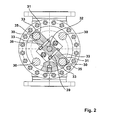
- Fig. 2
- zeigt einen Schnitt gemäß der Linie II-II aus
Fig. 1 . - Der insgesamt mit 1 bezeichnete Schieber besitzt das Schiebergehäuse 2, das in einer Rohrleitung 3 einsitzt, d. h. zu beiden Seiten des Schiebergehäuses ist die Rohrleitung 3 angeflanscht. Das Schiebergehäuse 2 weist eine Keilaufnahme 5 zur Aufnahme des Schieberkeiles 10 auf. Der Schieberkeil 10 sitzt in der Keilaufnahme abgedichtet ein, wobei zur Abdichtung am Schieberkeil angeordnete Dichtungen 11 sowie an der Keilaufnahme angeordnete Dichtungen 6 vorgesehen sind. An dem Schieberkeil 10, der in der Ansicht entsprechend dem Querschnitt der Rohrleitung in etwa kreisförmig ausgebildet ist, angeordnet ist der insgesamt mit 20 bezeichnete Spindeltrieb. Der Spindeltrieb 20 ist in einem Spindelkopf 22 gelagert, wobei zur Lagerung der Spindel in dem Spindelkopf 22 ein Gewindetrieb 23 vorgesehen ist, der in Verbindung mit einem Motor (nicht dargestellt) dem Antrieb der Spindel 25 des Spindeltriebes dient. Der Spindelkopf 22 ist durch vier Säulen 30 mit dem Schiebergehäuse 2 verbunden (
Fig. 2 ). Der Gewindetrieb ist beispielsweise als Rollengewindetrieb oder als Planetenrollengewindetrieb ausgebildet. An die Spindel 25 schließt sich die Achse 28 an, die über die insgesamt mit 29 bezeichnete Kupplung mit der Spindel 25 des Spindeltriebes 20 in Verbindung steht. Die Spindel besteht aus einem hochfesten Werkzeug- oder Schraubenstahl, wohingegen die Achse aus einem korrosionsbeständigen Material, z. B. einem Edelstahl ausgebildet ist. - Wie bereits ausgeführt, steht der Spindelkopf 22 mit dem Schiebergehäuse 2 durch mindestens zwei, vorzugsweise vier parallel zueinander verlaufende Säulen 30 in Verbindung, wobei ein Kupplungssteg 31 vorgesehen ist, der den Spindeltrieb 20 mit zwei Säulen 30 verschieblich verbindet. Um ein Gleiten des Kupplungssteges 31 auf der Säule 30 zu gewährleisten, ist in dem Kupplungssteg im Bereich der Säule 30 eine Lagerbuchse 35 in Form eines Gleitlagers oder ein entsprechendes Kugel-oder Rollenlager (
Fig. 2 ) vorgesehen. - Es wurde bereits darauf hingewiesen, dass der Antriebsmotor eine Steuerung aufweist, die dafür sorgt, dass dann wenn der Schieberkeil 10 in der Keilaufnahme 5 seine Endstellung erreicht hat, der Motor (nicht dargestellt) stillgesetzt wird. Für den Fall, dass die Steuerung versagt, ist ein unterer Anschlag 34a und ein oberer Anschlag 34b im Bereich der Enden zumindest einer Säule 30 vorgesehen, gegen den der Kupplungssteg 31 anschlägt, wenn der Motor die Spindel versucht zu überdrehen. Hierdurch wird zum einen verhindert, dass der Schieberkeil 10 mit übermäßiger Kraft in die Keilaufnahme 5 eingepresst wird, mit der Folge, dass zumindest die Dichtungen 6, 11 beschädigt werden oder gar der ganze Schieberkeil bzw. die Keilaufnahme in dem Schiebergehäuse.
- Zum anderen verhindert der Kupplungssteg bei einem Überdrehen des Motors, dass der Spindeltrieb 20 ausbaucht. Das heißt, der Kupplungssteg stabilisiert den Spindeltrieb insbesondere für den Fall, dass die Steuerung zum Stillsitzen des Spindeltriebes nach Durchlaufen eines bestimmten Weges den Antrieb nicht stillsetzt.
- Darüber hinaus bildet der Kupplungssteg 31 mit einer im Bereich der Enden der Achse und der Spindel angeordneten Manschette 32 die Kupplung insofern, als durch die Manschette des Kupplungssteges die beiden Enden von Spindel und Achse in axialer Richtung kraftübertragend zusammengehalten sind (
Fig. 2 ). Hierzu sind die beiden Stegschalen 33 des Kupplungssteges 31 zu beiden Seiten der Manschette 32 durch eine Schraubenverbindung 39 verbunden. - Zur in axialer Richtung kraftübertragender Verbindung zwischen Spindel und Welle ist folgendes auszuführen. Die Enden der Spindel und der Welle stehen fluchtend zueinander aufeinander. Im Bereich der Manschette 32 des Kupplungssteges weisen sowohl die Achse als auch die Spindel eine Nut, insbesondere eine umlaufende Nut 36, 37 auf. In diese Nuten greift die Manschette mit entsprechenden Vorsprüngen (nicht dargestellt) ein, sodass eine formschlüssige Verbindung zwischen Spindel und Achse durch die Manschette des Kupplungssteges herbeigeführt ist.
-
- 1
- Schieber
- 2
- Schiebergehäuse
- 3
- Rohrleitung
- 5
- Keilaufnahme
- 6
- Dichtung
- 10
- Schieberkeil
- 11
- Dichtung
- 20
- Spindeltrieb
- 22
- Spindelkopf
- 23
- Gewindetrieb
- 25
- Spindel
- 28
- Achse
- 29
- Kupplung
- 30
- Säule
- 31
- Kupplungssteg
- 32
- Manschette
- 33
- Stegschale
- 34a
- unterer Anschlag
- 34b
- oberer Anschlag
- 35
- Lagerbuchse
- 36
- umlaufende Nut in der Spindel
- 37
- umlaufende Nut in der Achse
- 39
- Schraubverbindung für die Stegschalen
Claims (10)
- Schieber (1) umfassend ein Schiebergehäuse (2), wobei das Schiebergehäuse (2) einen Spindeltrieb (20) aufweist, wobei der Spindeltrieb (20) an seinem einen Ende einen Schieberkeil (10) zum Absperren einer Rohrleitung (3) aufweist, wobei der Spindeltrieb (20) eine motorisch angetriebene Spindel (25) umfasst,
dadurch gekennzeichnet,
dass die Spindel (25) durch eine Kupplung (29) axial verschieblich mit einer Achse (28) verbunden ist, wobei die Achse (28) endseitig den Schieberkeil (10) aufweist. - Schieber (1) nach Anspruch 1,
dadurch gekennzeichnet,
dass der Spindeltrieb (20) im Bereich der Kupplung (29) einen Kupplungssteg (31) aufweist, wobei der Kupplungssteg (31) durch mindestens eine parallel zum Spindeltrieb (20) sich erstreckende Säule (30) verschieblich geführt ist. - Schieber (1) nach Anspruch 2,
dadurch gekennzeichnet,
dass der Kupplungssteg (31) zwei Stegschalen (33) umfasst, die im Bereich der Säule (30) eine Lagerbuchse (35) bilden. - Schieber (1) nach Anspruch 3,
dadurch gekennzeichnet,
dass die Lagerbuchse (35) ein Gleit- oder ein Kugellager aufweist. - Schieber (1) nach einem der Ansprüche 2 bis 4,
dadurch gekennzeichnet,
dass die Säule (30) zumindest einen unteren Anschlag (34a) für den Kupplungssteg (31) zeigt. - Schieber (1) nach einem der voranstehenden Ansprüche,
dadurch gekennzeichnet,
dass die Achse (28) zur Aufnahme des Schieberkeils (10) aus einem korrosionsbeständigen Material ausgebildet ist. - Schieber (1) nach einem der voranstehenden Ansprüche 2 bis 6, dadurch gekennzeichnet,
dass die Kupplung (29) eine im Kupplungssteg (31) angeordnete Manschette (32) umfasst, die form- oder kraftschlüssig sowohl mit der Spindel (25) als auch mit der Achse (28) in Verbindung steht. - Schieber (1) nach Anspruch 7,
dadurch gekennzeichnet,
dass sowohl die Achse (28) als auch die Spindel (25) eine Nut (36, 37) aufweisen, in die Vorsprünge in der Manschette (32) eingreifen. - Schieber (1) nach einem der voranstehenden Ansprüche,
dadurch gekennzeichnet,
dass die Spindel (25) als Rollengewindetrieb ausgebildet ist. - Schieber (1) nach einem der voranstehenden Ansprüche,
dadurch gekennzeichnet,
dass die Spindel als Planetenrollengewindetrieb ausgebildet ist.
Priority Applications (4)
| Application Number | Priority Date | Filing Date | Title |
|---|---|---|---|
| DK12002428T DK2647892T3 (en) | 2012-04-03 | 2012-04-03 | Shooting extensively a shooting house |
| EP20120002428 EP2647892B1 (de) | 2012-04-03 | 2012-04-03 | Schieber umfassend ein Schiebergehäuse |
| US13/856,188 US9010728B2 (en) | 2012-04-03 | 2013-04-03 | Gate valve comprising a valve body |
| CN201310114178.4A CN103363139B (zh) | 2012-04-03 | 2013-04-03 | 包括阀体的闸阀 |
Applications Claiming Priority (1)
| Application Number | Priority Date | Filing Date | Title |
|---|---|---|---|
| EP20120002428 EP2647892B1 (de) | 2012-04-03 | 2012-04-03 | Schieber umfassend ein Schiebergehäuse |
Publications (2)
| Publication Number | Publication Date |
|---|---|
| EP2647892A1 true EP2647892A1 (de) | 2013-10-09 |
| EP2647892B1 EP2647892B1 (de) | 2014-12-31 |
Family
ID=45976621
Family Applications (1)
| Application Number | Title | Priority Date | Filing Date |
|---|---|---|---|
| EP20120002428 Active EP2647892B1 (de) | 2012-04-03 | 2012-04-03 | Schieber umfassend ein Schiebergehäuse |
Country Status (4)
| Country | Link |
|---|---|
| US (1) | US9010728B2 (de) |
| EP (1) | EP2647892B1 (de) |
| CN (1) | CN103363139B (de) |
| DK (1) | DK2647892T3 (de) |
Cited By (1)
| Publication number | Priority date | Publication date | Assignee | Title |
|---|---|---|---|---|
| DE202017105252U1 (de) | 2017-08-31 | 2017-10-23 | Samson Ag | Stellgerät für verfahrenstechnische Anlagen |
Families Citing this family (6)
| Publication number | Priority date | Publication date | Assignee | Title |
|---|---|---|---|---|
| CN103615553B (zh) * | 2013-11-25 | 2016-02-10 | 江苏远望仪器有限公司 | 艏尖舱防撞阀 |
| GB2564491A (en) * | 2017-07-14 | 2019-01-16 | Biofold Fluidpower Ltd | Failsafe valve actuator |
| DE102018101472A1 (de) | 2018-01-23 | 2019-07-25 | Z & J Technologies Gmbh | Schieberventil und Verwendung eines Schieberventils |
| CN111692353A (zh) * | 2019-03-14 | 2020-09-22 | 汤宝田 | 闸板式智能阀门 |
| US11204104B2 (en) * | 2019-05-16 | 2021-12-21 | Tapcoenpro, Llc | Systems and methods for torque isolation valve actuator |
| DE202019104694U1 (de) | 2019-08-27 | 2019-10-09 | Samson Ag | Stellgerät für eine verfahrenstechnische Anlage |
Citations (4)
| Publication number | Priority date | Publication date | Assignee | Title |
|---|---|---|---|---|
| DE1226847B (de) * | 1963-06-18 | 1966-10-13 | Honeywell Ges Mit Beschraenkte | Umkehrbarer Druckmittelantrieb fuer Regelventile, Drosselklappen od. dgl. |
| DE2635688A1 (de) * | 1976-08-07 | 1978-02-09 | Remmert Alfred | Dampfventil |
| DE3342998A1 (de) * | 1982-12-21 | 1984-07-05 | Sigma Koncern, Olmütz/Olomouc | Kupplungsstueck fuer geteilte armaturenspindeln |
| DE10014796A1 (de) * | 2000-03-24 | 2001-10-11 | Noval Industriearmaturen Gmbh | Deckelloses Hochdruckventil |
Family Cites Families (6)
| Publication number | Priority date | Publication date | Assignee | Title |
|---|---|---|---|---|
| US2515498A (en) * | 1945-07-16 | 1950-07-18 | Crane Co | Toggle operating mechanism for valves |
| US5271602A (en) * | 1992-04-13 | 1993-12-21 | The Japan Steel Works Ltd. | Vacuum gate valve |
| EP1116908B1 (de) * | 1999-06-29 | 2004-05-06 | Ampo, S. Coop. | Ventil für anlagen zur aluminiumproduktion |
| US6517049B2 (en) * | 2001-07-12 | 2003-02-11 | Los Angeles Pump And Valve Products | Method and valve for controlling fluid flow, and method of servicing valve |
| EP1419334B1 (de) * | 2001-08-24 | 2006-11-08 | FMC Technologies, Inc. | Drehkraftreduziertes schieberventil mit wälzschraubtrieb |
| CN2643088Y (zh) * | 2002-12-03 | 2004-09-22 | 朱文 | 超轻力矩高温高压截止阀 |
-
2012
- 2012-04-03 DK DK12002428T patent/DK2647892T3/en active
- 2012-04-03 EP EP20120002428 patent/EP2647892B1/de active Active
-
2013
- 2013-04-03 US US13/856,188 patent/US9010728B2/en active Active
- 2013-04-03 CN CN201310114178.4A patent/CN103363139B/zh not_active Expired - Fee Related
Patent Citations (4)
| Publication number | Priority date | Publication date | Assignee | Title |
|---|---|---|---|---|
| DE1226847B (de) * | 1963-06-18 | 1966-10-13 | Honeywell Ges Mit Beschraenkte | Umkehrbarer Druckmittelantrieb fuer Regelventile, Drosselklappen od. dgl. |
| DE2635688A1 (de) * | 1976-08-07 | 1978-02-09 | Remmert Alfred | Dampfventil |
| DE3342998A1 (de) * | 1982-12-21 | 1984-07-05 | Sigma Koncern, Olmütz/Olomouc | Kupplungsstueck fuer geteilte armaturenspindeln |
| DE10014796A1 (de) * | 2000-03-24 | 2001-10-11 | Noval Industriearmaturen Gmbh | Deckelloses Hochdruckventil |
Cited By (1)
| Publication number | Priority date | Publication date | Assignee | Title |
|---|---|---|---|---|
| DE202017105252U1 (de) | 2017-08-31 | 2017-10-23 | Samson Ag | Stellgerät für verfahrenstechnische Anlagen |
Also Published As
| Publication number | Publication date |
|---|---|
| EP2647892B1 (de) | 2014-12-31 |
| US20140306134A1 (en) | 2014-10-16 |
| CN103363139A (zh) | 2013-10-23 |
| US9010728B2 (en) | 2015-04-21 |
| DK2647892T3 (en) | 2015-02-09 |
| CN103363139B (zh) | 2015-09-02 |
Similar Documents
| Publication | Publication Date | Title |
|---|---|---|
| EP2647892B1 (de) | Schieber umfassend ein Schiebergehäuse | |
| DE19913200B4 (de) | Lageranordnung für einen Gewindetrieb | |
| DE112012007184T5 (de) | Wellenendadapter und Kugelrollspindelaufbau | |
| DE2164543C3 (de) | Teleskopwelle | |
| DE2421328C2 (de) | Linear-Rollenlager | |
| EP2478996B1 (de) | Werkzeugwechsler | |
| EP3728102B1 (de) | Spindelwelleneinheit für eine vorrichtung zum drehverschliessen von behältern mit einem schraubverschluss | |
| DE3407551A1 (de) | Aufnahmekopf fuer mess- und/oder montagevorgaenge | |
| DE2629686A1 (de) | Zahnstangentrieb fuer ein lenkgetriebe | |
| EP2277666A1 (de) | Innenauszieher für Wälzlager oder dergleichen | |
| DE60223959T2 (de) | Kugelumlaufspindelbetrieb | |
| DE4441019C2 (de) | Wellenkupplung | |
| DE4013896C1 (en) | Pre-tension adjuster for ball bearings - has end of sleeve bearing against fixed end-stop in housing | |
| DE102018218675B4 (de) | Lenksystem | |
| DE3542478A1 (de) | Linearkugellager fuer schlitten in werkzeugmaschinen oder dgl. | |
| DE102019134040A1 (de) | Reinigungsvorrichtung | |
| EP2640623B1 (de) | Rollengelagerte zahnstangenführung | |
| DE102010005537A1 (de) | Axial verspanntes Wälzlager | |
| DE3511483C2 (de) | ||
| DE102007038064A1 (de) | Verstelleinrichtung zur Positionierung einer axial geführten Maschineneinheit | |
| EP3372869B1 (de) | Stellantrieb | |
| DE202023101293U1 (de) | Stellantrieb für eine Armatur | |
| DE532998C (de) | ||
| DE2215578C3 (de) | Vorrichtung zum hydraulischen Betätigen von Entleerventilen | |
| EP2292942B1 (de) | Linearstellglied mit Stützlager |
Legal Events
| Date | Code | Title | Description |
|---|---|---|---|
| PUAI | Public reference made under article 153(3) epc to a published international application that has entered the european phase |
Free format text: ORIGINAL CODE: 0009012 |
|
| 17P | Request for examination filed |
Effective date: 20120921 |
|
| AK | Designated contracting states |
Kind code of ref document: A1 Designated state(s): AL AT BE BG CH CY CZ DE DK EE ES FI FR GB GR HR HU IE IS IT LI LT LU LV MC MK MT NL NO PL PT RO RS SE SI SK SM TR |
|
| AX | Request for extension of the european patent |
Extension state: BA ME |
|
| GRAP | Despatch of communication of intention to grant a patent |
Free format text: ORIGINAL CODE: EPIDOSNIGR1 |
|
| INTG | Intention to grant announced |
Effective date: 20140725 |
|
| GRAS | Grant fee paid |
Free format text: ORIGINAL CODE: EPIDOSNIGR3 |
|
| GRAA | (expected) grant |
Free format text: ORIGINAL CODE: 0009210 |
|
| AK | Designated contracting states |
Kind code of ref document: B1 Designated state(s): AL AT BE BG CH CY CZ DE DK EE ES FI FR GB GR HR HU IE IS IT LI LT LU LV MC MK MT NL NO PL PT RO RS SE SI SK SM TR |
|
| REG | Reference to a national code |
Ref country code: CH Ref legal event code: EP Ref country code: GB Ref legal event code: FG4D Free format text: NOT ENGLISH |
|
| REG | Reference to a national code |
Ref country code: IE Ref legal event code: FG4D Free format text: LANGUAGE OF EP DOCUMENT: GERMAN |
|
| REG | Reference to a national code |
Ref country code: DK Ref legal event code: T3 Effective date: 20150203 |
|
| REG | Reference to a national code |
Ref country code: NL Ref legal event code: T3 |
|
| REG | Reference to a national code |
Ref country code: AT Ref legal event code: REF Ref document number: 704623 Country of ref document: AT Kind code of ref document: T Effective date: 20150215 |
|
| REG | Reference to a national code |
Ref country code: DE Ref legal event code: R096 Ref document number: 502012001921 Country of ref document: DE Effective date: 20150219 |
|
| REG | Reference to a national code |
Ref country code: SE Ref legal event code: TRGR |
|
| REG | Reference to a national code |
Ref country code: FR Ref legal event code: PLFP Year of fee payment: 4 |
|
| PG25 | Lapsed in a contracting state [announced via postgrant information from national office to epo] |
Ref country code: LT Free format text: LAPSE BECAUSE OF FAILURE TO SUBMIT A TRANSLATION OF THE DESCRIPTION OR TO PAY THE FEE WITHIN THE PRESCRIBED TIME-LIMIT Effective date: 20141231 |
|
| REG | Reference to a national code |
Ref country code: NO Ref legal event code: T2 Effective date: 20141231 |
|
| REG | Reference to a national code |
Ref country code: LT Ref legal event code: MG4D |
|
| PG25 | Lapsed in a contracting state [announced via postgrant information from national office to epo] |
Ref country code: GR Free format text: LAPSE BECAUSE OF FAILURE TO SUBMIT A TRANSLATION OF THE DESCRIPTION OR TO PAY THE FEE WITHIN THE PRESCRIBED TIME-LIMIT Effective date: 20150401 Ref country code: RS Free format text: LAPSE BECAUSE OF FAILURE TO SUBMIT A TRANSLATION OF THE DESCRIPTION OR TO PAY THE FEE WITHIN THE PRESCRIBED TIME-LIMIT Effective date: 20141231 Ref country code: LV Free format text: LAPSE BECAUSE OF FAILURE TO SUBMIT A TRANSLATION OF THE DESCRIPTION OR TO PAY THE FEE WITHIN THE PRESCRIBED TIME-LIMIT Effective date: 20141231 Ref country code: HR Free format text: LAPSE BECAUSE OF FAILURE TO SUBMIT A TRANSLATION OF THE DESCRIPTION OR TO PAY THE FEE WITHIN THE PRESCRIBED TIME-LIMIT Effective date: 20141231 |
|
| PG25 | Lapsed in a contracting state [announced via postgrant information from national office to epo] |
Ref country code: RO Free format text: LAPSE BECAUSE OF FAILURE TO SUBMIT A TRANSLATION OF THE DESCRIPTION OR TO PAY THE FEE WITHIN THE PRESCRIBED TIME-LIMIT Effective date: 20141231 Ref country code: SK Free format text: LAPSE BECAUSE OF FAILURE TO SUBMIT A TRANSLATION OF THE DESCRIPTION OR TO PAY THE FEE WITHIN THE PRESCRIBED TIME-LIMIT Effective date: 20141231 Ref country code: ES Free format text: LAPSE BECAUSE OF FAILURE TO SUBMIT A TRANSLATION OF THE DESCRIPTION OR TO PAY THE FEE WITHIN THE PRESCRIBED TIME-LIMIT Effective date: 20141231 |
|
| REG | Reference to a national code |
Ref country code: HU Ref legal event code: AG4A Ref document number: E023531 Country of ref document: HU |
|
| PG25 | Lapsed in a contracting state [announced via postgrant information from national office to epo] |
Ref country code: PL Free format text: LAPSE BECAUSE OF FAILURE TO SUBMIT A TRANSLATION OF THE DESCRIPTION OR TO PAY THE FEE WITHIN THE PRESCRIBED TIME-LIMIT Effective date: 20141231 Ref country code: IS Free format text: LAPSE BECAUSE OF FAILURE TO SUBMIT A TRANSLATION OF THE DESCRIPTION OR TO PAY THE FEE WITHIN THE PRESCRIBED TIME-LIMIT Effective date: 20150430 |
|
| REG | Reference to a national code |
Ref country code: DE Ref legal event code: R097 Ref document number: 502012001921 Country of ref document: DE |
|
| PG25 | Lapsed in a contracting state [announced via postgrant information from national office to epo] |
Ref country code: EE Free format text: LAPSE BECAUSE OF FAILURE TO SUBMIT A TRANSLATION OF THE DESCRIPTION OR TO PAY THE FEE WITHIN THE PRESCRIBED TIME-LIMIT Effective date: 20141231 |
|
| PLBE | No opposition filed within time limit |
Free format text: ORIGINAL CODE: 0009261 |
|
| STAA | Information on the status of an ep patent application or granted ep patent |
Free format text: STATUS: NO OPPOSITION FILED WITHIN TIME LIMIT |
|
| PG25 | Lapsed in a contracting state [announced via postgrant information from national office to epo] |
Ref country code: MC Free format text: LAPSE BECAUSE OF FAILURE TO SUBMIT A TRANSLATION OF THE DESCRIPTION OR TO PAY THE FEE WITHIN THE PRESCRIBED TIME-LIMIT Effective date: 20141231 Ref country code: LU Free format text: LAPSE BECAUSE OF FAILURE TO SUBMIT A TRANSLATION OF THE DESCRIPTION OR TO PAY THE FEE WITHIN THE PRESCRIBED TIME-LIMIT Effective date: 20150403 |
|
| 26N | No opposition filed |
Effective date: 20151001 |
|
| REG | Reference to a national code |
Ref country code: IE Ref legal event code: MM4A |
|
| PG25 | Lapsed in a contracting state [announced via postgrant information from national office to epo] |
Ref country code: SI Free format text: LAPSE BECAUSE OF FAILURE TO SUBMIT A TRANSLATION OF THE DESCRIPTION OR TO PAY THE FEE WITHIN THE PRESCRIBED TIME-LIMIT Effective date: 20141231 |
|
| REG | Reference to a national code |
Ref country code: FR Ref legal event code: PLFP Year of fee payment: 5 |
|
| PG25 | Lapsed in a contracting state [announced via postgrant information from national office to epo] |
Ref country code: IE Free format text: LAPSE BECAUSE OF NON-PAYMENT OF DUE FEES Effective date: 20150403 |
|
| PGFP | Annual fee paid to national office [announced via postgrant information from national office to epo] |
Ref country code: FI Payment date: 20160413 Year of fee payment: 5 Ref country code: CZ Payment date: 20160401 Year of fee payment: 5 Ref country code: NO Payment date: 20160422 Year of fee payment: 5 |
|
| PGFP | Annual fee paid to national office [announced via postgrant information from national office to epo] |
Ref country code: DK Payment date: 20160420 Year of fee payment: 5 Ref country code: BE Payment date: 20160420 Year of fee payment: 5 Ref country code: IT Payment date: 20160427 Year of fee payment: 5 Ref country code: HU Payment date: 20160420 Year of fee payment: 5 |
|
| PG25 | Lapsed in a contracting state [announced via postgrant information from national office to epo] |
Ref country code: MT Free format text: LAPSE BECAUSE OF FAILURE TO SUBMIT A TRANSLATION OF THE DESCRIPTION OR TO PAY THE FEE WITHIN THE PRESCRIBED TIME-LIMIT Effective date: 20141231 |
|
| REG | Reference to a national code |
Ref country code: FR Ref legal event code: PLFP Year of fee payment: 6 |
|
| PG25 | Lapsed in a contracting state [announced via postgrant information from national office to epo] |
Ref country code: BG Free format text: LAPSE BECAUSE OF FAILURE TO SUBMIT A TRANSLATION OF THE DESCRIPTION OR TO PAY THE FEE WITHIN THE PRESCRIBED TIME-LIMIT Effective date: 20141231 Ref country code: SM Free format text: LAPSE BECAUSE OF FAILURE TO SUBMIT A TRANSLATION OF THE DESCRIPTION OR TO PAY THE FEE WITHIN THE PRESCRIBED TIME-LIMIT Effective date: 20141231 |
|
| PG25 | Lapsed in a contracting state [announced via postgrant information from national office to epo] |
Ref country code: CY Free format text: LAPSE BECAUSE OF FAILURE TO SUBMIT A TRANSLATION OF THE DESCRIPTION OR TO PAY THE FEE WITHIN THE PRESCRIBED TIME-LIMIT Effective date: 20141231 |
|
| PG25 | Lapsed in a contracting state [announced via postgrant information from national office to epo] |
Ref country code: PT Free format text: LAPSE BECAUSE OF FAILURE TO SUBMIT A TRANSLATION OF THE DESCRIPTION OR TO PAY THE FEE WITHIN THE PRESCRIBED TIME-LIMIT Effective date: 20150501 |
|
| PG25 | Lapsed in a contracting state [announced via postgrant information from national office to epo] |
Ref country code: TR Free format text: LAPSE BECAUSE OF FAILURE TO SUBMIT A TRANSLATION OF THE DESCRIPTION OR TO PAY THE FEE WITHIN THE PRESCRIBED TIME-LIMIT Effective date: 20141231 |
|
| PG25 | Lapsed in a contracting state [announced via postgrant information from national office to epo] |
Ref country code: CZ Free format text: LAPSE BECAUSE OF NON-PAYMENT OF DUE FEES Effective date: 20170403 |
|
| REG | Reference to a national code |
Ref country code: DK Ref legal event code: EBP Effective date: 20170430 |
|
| REG | Reference to a national code |
Ref country code: NO Ref legal event code: MMEP |
|
| PG25 | Lapsed in a contracting state [announced via postgrant information from national office to epo] |
Ref country code: HU Free format text: LAPSE BECAUSE OF NON-PAYMENT OF DUE FEES Effective date: 20170404 Ref country code: NO Free format text: LAPSE BECAUSE OF NON-PAYMENT OF DUE FEES Effective date: 20170430 Ref country code: FI Free format text: LAPSE BECAUSE OF NON-PAYMENT OF DUE FEES Effective date: 20170403 |
|
| REG | Reference to a national code |
Ref country code: BE Ref legal event code: MM Effective date: 20170430 |
|
| REG | Reference to a national code |
Ref country code: FR Ref legal event code: PLFP Year of fee payment: 7 |
|
| PG25 | Lapsed in a contracting state [announced via postgrant information from national office to epo] |
Ref country code: DK Free format text: LAPSE BECAUSE OF NON-PAYMENT OF DUE FEES Effective date: 20170430 |
|
| PG25 | Lapsed in a contracting state [announced via postgrant information from national office to epo] |
Ref country code: BE Free format text: LAPSE BECAUSE OF NON-PAYMENT OF DUE FEES Effective date: 20170430 Ref country code: IT Free format text: LAPSE BECAUSE OF NON-PAYMENT OF DUE FEES Effective date: 20170403 |
|
| REG | Reference to a national code |
Ref country code: AT Ref legal event code: MM01 Ref document number: 704623 Country of ref document: AT Kind code of ref document: T Effective date: 20170403 |
|
| PG25 | Lapsed in a contracting state [announced via postgrant information from national office to epo] |
Ref country code: MK Free format text: LAPSE BECAUSE OF FAILURE TO SUBMIT A TRANSLATION OF THE DESCRIPTION OR TO PAY THE FEE WITHIN THE PRESCRIBED TIME-LIMIT Effective date: 20141231 |
|
| PG25 | Lapsed in a contracting state [announced via postgrant information from national office to epo] |
Ref country code: AT Free format text: LAPSE BECAUSE OF NON-PAYMENT OF DUE FEES Effective date: 20170403 |
|
| PG25 | Lapsed in a contracting state [announced via postgrant information from national office to epo] |
Ref country code: AL Free format text: LAPSE BECAUSE OF FAILURE TO SUBMIT A TRANSLATION OF THE DESCRIPTION OR TO PAY THE FEE WITHIN THE PRESCRIBED TIME-LIMIT Effective date: 20141231 |
|
| PGFP | Annual fee paid to national office [announced via postgrant information from national office to epo] |
Ref country code: NL Payment date: 20230426 Year of fee payment: 12 |
|
| PGFP | Annual fee paid to national office [announced via postgrant information from national office to epo] |
Ref country code: FR Payment date: 20230426 Year of fee payment: 12 Ref country code: CH Payment date: 20230605 Year of fee payment: 12 |
|
| PGFP | Annual fee paid to national office [announced via postgrant information from national office to epo] |
Ref country code: SE Payment date: 20230426 Year of fee payment: 12 |
|
| PGFP | Annual fee paid to national office [announced via postgrant information from national office to epo] |
Ref country code: GB Payment date: 20230428 Year of fee payment: 12 |
|
| REG | Reference to a national code |
Ref country code: CH Ref legal event code: PL |
|
| REG | Reference to a national code |
Ref country code: SE Ref legal event code: EUG |
|
| REG | Reference to a national code |
Ref country code: NL Ref legal event code: MM Effective date: 20240501 |
|
| GBPC | Gb: european patent ceased through non-payment of renewal fee |
Effective date: 20240403 |
|
| PG25 | Lapsed in a contracting state [announced via postgrant information from national office to epo] |
Ref country code: NL Free format text: LAPSE BECAUSE OF NON-PAYMENT OF DUE FEES Effective date: 20240501 |
|
| PG25 | Lapsed in a contracting state [announced via postgrant information from national office to epo] |
Ref country code: GB Free format text: LAPSE BECAUSE OF NON-PAYMENT OF DUE FEES Effective date: 20240403 |
|
| PG25 | Lapsed in a contracting state [announced via postgrant information from national office to epo] |
Ref country code: FR Free format text: LAPSE BECAUSE OF NON-PAYMENT OF DUE FEES Effective date: 20240430 |
|
| PG25 | Lapsed in a contracting state [announced via postgrant information from national office to epo] |
Ref country code: NL Free format text: LAPSE BECAUSE OF NON-PAYMENT OF DUE FEES Effective date: 20240501 Ref country code: GB Free format text: LAPSE BECAUSE OF NON-PAYMENT OF DUE FEES Effective date: 20240403 Ref country code: FR Free format text: LAPSE BECAUSE OF NON-PAYMENT OF DUE FEES Effective date: 20240430 Ref country code: CH Free format text: LAPSE BECAUSE OF NON-PAYMENT OF DUE FEES Effective date: 20240430 |
|
| PGFP | Annual fee paid to national office [announced via postgrant information from national office to epo] |
Ref country code: DE Payment date: 20250321 Year of fee payment: 14 |
|
| PG25 | Lapsed in a contracting state [announced via postgrant information from national office to epo] |
Ref country code: SE Free format text: LAPSE BECAUSE OF NON-PAYMENT OF DUE FEES Effective date: 20240404 |