EP2648017B1 - Bordsystem zur Unterstützung der Steuerung eines Luftschiffs, das auf einem GNSS-System mit redundanter und ungleichartiger Architektur für ein hohes Integritätsniveau beruht - Google Patents
Bordsystem zur Unterstützung der Steuerung eines Luftschiffs, das auf einem GNSS-System mit redundanter und ungleichartiger Architektur für ein hohes Integritätsniveau beruht Download PDFInfo
- Publication number
- EP2648017B1 EP2648017B1 EP13161627.8A EP13161627A EP2648017B1 EP 2648017 B1 EP2648017 B1 EP 2648017B1 EP 13161627 A EP13161627 A EP 13161627A EP 2648017 B1 EP2648017 B1 EP 2648017B1
- Authority
- EP
- European Patent Office
- Prior art keywords
- gnss
- integrity
- navigation
- navigation signals
- module
- Prior art date
- Legal status (The legal status is an assumption and is not a legal conclusion. Google has not performed a legal analysis and makes no representation as to the accuracy of the status listed.)
- Active
Links
Images


Classifications
-
- G—PHYSICS
- G01—MEASURING; TESTING
- G01S—RADIO DIRECTION-FINDING; RADIO NAVIGATION; DETERMINING DISTANCE OR VELOCITY BY USE OF RADIO WAVES; LOCATING OR PRESENCE-DETECTING BY USE OF THE REFLECTION OR RERADIATION OF RADIO WAVES; ANALOGOUS ARRANGEMENTS USING OTHER WAVES
- G01S19/00—Satellite radio beacon positioning systems; Determining position, velocity or attitude using signals transmitted by such systems
- G01S19/38—Determining a navigation solution using signals transmitted by a satellite radio beacon positioning system
- G01S19/39—Determining a navigation solution using signals transmitted by a satellite radio beacon positioning system the satellite radio beacon positioning system transmitting time-stamped messages, e.g. GPS [Global Positioning System], GLONASS [Global Orbiting Navigation Satellite System] or GALILEO
-
- G—PHYSICS
- G01—MEASURING; TESTING
- G01C—MEASURING DISTANCES, LEVELS OR BEARINGS; SURVEYING; NAVIGATION; GYROSCOPIC INSTRUMENTS; PHOTOGRAMMETRY OR VIDEOGRAMMETRY
- G01C21/00—Navigation; Navigational instruments not provided for in groups G01C1/00 - G01C19/00
- G01C21/10—Navigation; Navigational instruments not provided for in groups G01C1/00 - G01C19/00 by using measurements of speed or acceleration
- G01C21/12—Navigation; Navigational instruments not provided for in groups G01C1/00 - G01C19/00 by using measurements of speed or acceleration executed aboard the object being navigated; Dead reckoning
- G01C21/16—Navigation; Navigational instruments not provided for in groups G01C1/00 - G01C19/00 by using measurements of speed or acceleration executed aboard the object being navigated; Dead reckoning by integrating acceleration or speed, i.e. inertial navigation
- G01C21/165—Navigation; Navigational instruments not provided for in groups G01C1/00 - G01C19/00 by using measurements of speed or acceleration executed aboard the object being navigated; Dead reckoning by integrating acceleration or speed, i.e. inertial navigation combined with non-inertial navigation instruments
-
- G—PHYSICS
- G01—MEASURING; TESTING
- G01C—MEASURING DISTANCES, LEVELS OR BEARINGS; SURVEYING; NAVIGATION; GYROSCOPIC INSTRUMENTS; PHOTOGRAMMETRY OR VIDEOGRAMMETRY
- G01C21/00—Navigation; Navigational instruments not provided for in groups G01C1/00 - G01C19/00
- G01C21/20—Instruments for performing navigational calculations
-
- G—PHYSICS
- G01—MEASURING; TESTING
- G01S—RADIO DIRECTION-FINDING; RADIO NAVIGATION; DETERMINING DISTANCE OR VELOCITY BY USE OF RADIO WAVES; LOCATING OR PRESENCE-DETECTING BY USE OF THE REFLECTION OR RERADIATION OF RADIO WAVES; ANALOGOUS ARRANGEMENTS USING OTHER WAVES
- G01S19/00—Satellite radio beacon positioning systems; Determining position, velocity or attitude using signals transmitted by such systems
- G01S19/01—Satellite radio beacon positioning systems transmitting time-stamped messages, e.g. GPS [Global Positioning System], GLONASS [Global Orbiting Navigation Satellite System] or GALILEO
- G01S19/13—Receivers
- G01S19/14—Receivers specially adapted for specific applications
- G01S19/15—Aircraft landing systems
-
- G—PHYSICS
- G01—MEASURING; TESTING
- G01S—RADIO DIRECTION-FINDING; RADIO NAVIGATION; DETERMINING DISTANCE OR VELOCITY BY USE OF RADIO WAVES; LOCATING OR PRESENCE-DETECTING BY USE OF THE REFLECTION OR RERADIATION OF RADIO WAVES; ANALOGOUS ARRANGEMENTS USING OTHER WAVES
- G01S19/00—Satellite radio beacon positioning systems; Determining position, velocity or attitude using signals transmitted by such systems
- G01S19/01—Satellite radio beacon positioning systems transmitting time-stamped messages, e.g. GPS [Global Positioning System], GLONASS [Global Orbiting Navigation Satellite System] or GALILEO
- G01S19/13—Receivers
- G01S19/20—Integrity monitoring, fault detection or fault isolation of space segment
-
- G—PHYSICS
- G05—CONTROLLING; REGULATING
- G05D—SYSTEMS FOR CONTROLLING OR REGULATING NON-ELECTRIC VARIABLES
- G05D1/00—Control of position, course, altitude or attitude of land, water, air or space vehicles, e.g. using automatic pilots
- G05D1/04—Control of altitude or depth
- G05D1/042—Control of altitude or depth specially adapted for aircraft
-
- G—PHYSICS
- G05—CONTROLLING; REGULATING
- G05B—CONTROL OR REGULATING SYSTEMS IN GENERAL; FUNCTIONAL ELEMENTS OF SUCH SYSTEMS; MONITORING OR TESTING ARRANGEMENTS FOR SUCH SYSTEMS OR ELEMENTS
- G05B1/00—Comparing elements, i.e. elements for effecting comparison directly or indirectly between a desired value and existing or anticipated values
- G05B1/01—Comparing elements, i.e. elements for effecting comparison directly or indirectly between a desired value and existing or anticipated values electric
- G05B1/04—Comparing elements, i.e. elements for effecting comparison directly or indirectly between a desired value and existing or anticipated values electric with sensing of the position of the pointer of a measuring instrument
-
- G—PHYSICS
- G16—INFORMATION AND COMMUNICATION TECHNOLOGY [ICT] SPECIALLY ADAPTED FOR SPECIFIC APPLICATION FIELDS
- G16Z—INFORMATION AND COMMUNICATION TECHNOLOGY [ICT] SPECIALLY ADAPTED FOR SPECIFIC APPLICATION FIELDS, NOT OTHERWISE PROVIDED FOR
- G16Z99/00—Subject matter not provided for in other main groups of this subclass
Definitions
- the subject of the invention is an on-board aircraft management aid system of the type known by the acronym GLS (GNSS Landing System).
- GLS GNSS Landing System
- piloting assistance in the approach phase that is to say the phase that precedes the landing of the aircraft.
- the field of the invention is that of flight control systems based on the use of GNSS systems.
- a GLS-type piloting aid system makes it possible to provide angular and metric guidance deviations along an approach path of an aircraft to a runway of an airport of a quality sufficient to allow the landing and automatic taxiing of the aircraft in almost zero visibility conditions.
- GNSS Global Navigation Satellite System
- GBAS Ground Based Augmentation System
- a so-called Category I approach does not allow for landing but only to approach the landing zone to a so-called decision height of 100 feet.
- a Category I approach has safety requirements quantified by a risk of providing undetected false outputs of less than 10 -7 per hour.
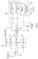
- FIG. figure 1 A first type of architecture, based on single-channel GNSS receiver, is represented in FIG. figure 1 . It consists essentially of a GNSS receiver 101, for example of the GPS or GPS / SBAS type (Satellite Based Augmentation System) connected on the one hand, via amplification and filtering means 103, to a reception antenna 102 of GPS or GPS / SBAS satellite navigation radionavigation signals, and on the other hand to a VDB (VHF Data Broadcast) type decoder 105 which receives, via a VHF antenna 104, GBAS (Ground) type signals. Based Augmentation System) issued by a ground station.
- GPS or GPS / SBAS type Synchron Generation
- VDB VHF Data Broadcast
- GBAS Ground
- the VDB decoder 105 transmits to the GNSS receiver 101 a set of corrections, also called augmentation data, which make it possible to improve the reliability of the GNSS signals that are moreover received via the antenna 102.
- the GNSS receiver 101 realizes, from the signals GNSS and GBAS corrections, on the one hand a navigation function 111 and on the other hand an approach function 112 as well as a monitoring function 113.
- the navigation function 111 outputs a set of Position measurements, Speed and Time allowing navigation assistance.
- the approach function 112 outputs a set of similar measurements or deviations allowing the landing aid in the approach phase.
- the monitoring function 113 is used to guarantee an integrity risk adapted to operations with a limited criticality, for example "Major” operations for navigation or “Hazardous” for the approach.
- the integrity risk related to a hardware failure of the receiver must be limited to 10 -7 / h as explained above.
- a simple chain solution of the type represented in figure 1 does not meet the security requirements of operations whose level of integrity risk is more restrictive, for example operations classified "catastrophic" for which the risk of integrity must be less than 10 -9 / h. Indeed, to achieve such security requirements, it is necessary that the probability that a simple failure causes a lack of integrity is negligible compared to the integrity risk of 10 -9 / h. Taking a factor of 1000, the probability of occurrence of a single failure impacting the integrity should be less than 10 -12 / h, which is not achievable. Solutions based on the use of a simple chain are not protected against a simple failure because they do not define external monitoring means to detect this failure. Category III approaches are classified as "catastrophic" and can not be implemented by this type of single-chain solution.
- a second type of architecture, based on a dual-chain mechanism of GNSS modules is represented at figure 2 . Elements identical to the architectures of figures 1 and 2 are identified by the same references. Such an architecture is disclosed in US 5945943 .
- a second GNSS module 201 also called a second channel, is associated with the first GNSS receiver 101 in order to improve the integrity of the assembly. For this, a cross comparison of the outputs of each approach function 112,212 is performed via two comparators 211,213. A simple criterion makes it possible to eliminate guiding deviation measurements which are too dissimilar between the two modules. Lightened monitoring 214,215 is carried out in each GNSS module 101,201, but it does not guarantee an appropriate integrity risk for Category I operations.
- a single event can reveal the same design defect on the two chains 101, 201, rendering the comparison functions completely inoperative, since the two chains can produce a very similar integrity defect and consequently detectable by a simple comparator.
- HMI HMI vs + P .
- HMI Rx ⁇ 2 The above equation reflects the fact that the principle of double chain reduces the risk of integrity HMI Rx1, Rx2 independent HMI between 101,201 receivers by acting on the probability P. As against the risk of integrities Common HMI c can not be deleted.
- the aim of the invention is to design a GLS system which provides the level of integrity sufficient to guarantee the risk of providing undetected erroneous information at the desired level for Category III approach operations.
- the invention also makes it possible to prevent a simple failure from generating undetected erroneous information.
- the subject of the invention is thus a device for receiving radio navigation signals, for the assistance of piloting an aircraft, characterized in that it comprises a first master GNSS module and a second dissimilar slave GNSS module, the first master GNSS module comprising a first means for processing the radio navigation signals and a first guide data calculation means from the measurements provided by said first signal processing means, the second slave GNSS module comprising a second means for processing of the radio navigation signals and a second guide data calculation means from the measurements provided by said second signal processing means, each GNSS module further comprising means for comparing the outputs X g1 , X g2 of said first and second guidance data calculation means adapted to perform the following integrity test: X boy Wut ⁇ 1 - X boy Wut ⁇ 2 > K boy Wut .
- Kg being a predetermined detection threshold so as to obtain a given probability P nd of detection of an error impacting one or the other, or the two measurements X g1 , X g2 simultaneously and a probability of false alarm P fa given.
- the detection threshold Kg is determined from the following two inequalities: ⁇ K boy Wut ⁇ 1 2 ⁇ ⁇ ⁇ e - x 2 2 . dx ⁇ P fa and P nd ⁇ ⁇ - ⁇ K boy Wut ⁇ VAL max Variance X boy Wut ⁇ 1 , Variance X boy Wut ⁇ 2 - covariance X boy Wut ⁇ 1 X boy Wut ⁇ 2 1 2 ⁇ ⁇ ⁇ e - u 2 2 . of , with VAL the tolerable limit value of error on one of the measures X g1, X g2 below which the integrity of said measurements is guaranteed.
- the common sources of error between the first master GNSS module and the second slave GNSS module are eliminated from the calculation of the variance of the difference between the outputs X g1 , X g2 of said first and second means for calculating guidance data.
- the guidance data is at least equal to one of the following data: the horizontal position, the lateral deflection, the lateral rectilinear deviation, the vertical deflection, the vertical rectilinear deflection or the distance to the runway threshold.
- the comparison means first performs a compensation step, on the horizontal position guidance data, of the asynchronism between the first master GNSS module and the second slave GNSS module.
- the asynchronism can also be compensated by synchronizing the guidance data calculated on a characteristic component of the received radio navigation signal.
- the first and second GNSS modules have a hardware and / or software dissimilarity.
- the first and second GNSS modules are materially similar but implement the following dissimilar digital processes: different digital filtering, different correlators, allocation of different frequency planes.
- the device according to the invention comprises a separate antenna and preamplifier to power each GNSS module so as to limit the common sources of integrity defect.
- the integrity test is modified as follows: X boy Wut ⁇ 1 - X boy Wut ⁇ 2 > K boy Wut . Variance ⁇ X boy Wut ⁇ 1 - X boy Wut ⁇ 2 + b with b a measurement bias calculated from the prior knowledge of the distance between the two antennas.
- the device according to the invention comprises an antenna, a means for dividing the power of the signal received by the antenna and two separate pre-amplifiers for supplying each GNSS module so as to limit the common sources of defect. 'integrity.
- the subject of the invention is also a multimode receiver for aiding the navigation of an aircraft comprising an ILS instrument landing system and a device for receiving radio navigation signals according to the invention for implementing a landing aid function GLS in the approach phase.
- the invention further relates to a hybrid navigation aid system comprising a multimode receiver comprising an ILS instrument landing system and a GNSS-IRS hybridization inertial system comprising an IRS inertial system producing inertial data and a means hybridization of GNSS navigation data by said inertial data, characterized in that it further comprises a device for receiving radio navigation signals according to the invention, the first master GNSS module of which is integrated in said inertial system to provide said GNSS navigation data and the second slave GNSS module are integrated in said multimode receiver.
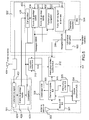
- the figure 3 schematizes the known architecture of a multimode receiver MMR for the implementation of navigation and landing aid functions, especially in the approach phase.
- the module for calculating the guide deviations generally consists of two different computers 303,304, the elements of which are continuously compared with one another. comparator 305, to detect operating anomalies. To avoid the common mode risk to the two computers 303,304, dissimilarities hardware and software are brought into the design of these two computers.
- MMR equipment is also intended to support the GLS landing aid function. To this end, it also integrates modules necessary for providing guidance information in ILS or MLS mode, a GNSS module 306 which receives the signals emitted by the radionavigation satellites via a satellite antenna 307, as well as VDB 308 module which allows the reception of messages sent by a GBAS ground station.
- GNSS module 306 which receives the signals emitted by the radionavigation satellites via a satellite antenna 307
- VDB 308 module which allows the reception of messages sent by a GBAS ground station.
- the autonomous location resulting from the reception of the satellite signals does not have sufficient performances to guide the aircraft during the approach and landing phase.
- the role of the GBAS ground station is mainly to broadcast correction messages necessary for the performance enhancement of a stand-alone GNSS receiver, as well as to broadcast the approaches of approaches that can be used on an airport at a given moment.
- the GLS function can only be used in current systems to support Category I approach operations that are less critical than Category III operations, and for which security requirements are less stringent.
- GLS function is supported by a simple chain GNSS computer, comprising a radio frequency analog module (not shown) for amplifying and digitizing the radio signals emitted by the satellites, and a calculation module 309 for extracting signals.
- digitized data Transmitted by satellites and distance measurements from these satellites to provide guidance deviation measurements 310.
- an SBAS satellite augmentation system may also be used to provide alternative guidance deviation measurements 311.
- the GNSS receiver 306 also includes a position calculation module for navigation 313 which also benefits from the corrections made by the GBAS or SBAS systems.
- the measurements provided by the navigation do not however concern the approach phase and are introduced as an indication.
- GBAS messages are transmitted in VHF frequency, received by the VHF antenna 302 of the MMR system, demodulated by the analog module 301 and decoded by the VDB decoder 308.
- the receiver emits lateral and vertical guidance deviations "GLS GAST-C" (for Category I approaches) or "GLS GAST-D” (for Category I to III approaches).
- the receiver MMR chooses, by means of the switch 312, between the different sources of pilot-controlled deviation of the pilot of the aircraft between deviations calculated from the ILS beam (or MLS), deviations calculated from GPS satellite data corrected by SBAS satellite data (SLS) and deviations calculated from GPS satellite data corrected by data from GBAS airport ground station (GLS).
- ILS beam or MLS
- SBAS satellite data SLS
- GLS GBAS airport ground station
- the GNSS receiver 306 transmits 314 navigation outputs consisting of a horizontal position for locating the aircraft and a speed used by the ADS-B (Automatic Dependent Surveillance Broadcast) functions of the aircraft. These outputs for the navigation 314 are currently calculated from the received L1 single frequency GPS signals corrected either by the GBAS ground station data or by the SBAS satellite data as a function of their availability.
- ADS-B Automatic Dependent Surveillance Broadcast
- New constellations for example those of the European GALILEO system, and new satellite transmission frequencies (frequency L5 in addition to frequency L1) make it possible to improve the availability, precision, continuity and integrity of the localization and the speed of the plane.
- the single-channel architecture according to the figure 3 With respect to the GLS function, it is not possible to deliver the high integrity signals capable of supporting type III approaches, given the risk of undetected error of the GNSS module 306.
- the figure 4 describes the architecture of an MMR receiver according to the invention implementing a GLS navigation aid function.
- the common elements between the architectures of figures 3 and 4 are identified by the same references.
- the GNSS receiver 306 of the architecture represented in FIG. figure 3 is replaced by a GNSS receiver 401, according to the invention, which integrates into the usual structure of an existing MMR device to make it compatible approach and landing capabilities in GLS category III.
- the GNSS receiver 401 comprises two dissimilar GNSS modules 402, 403, operating in a master-slave configuration.
- the GNSS receiver 401 is designed on the basis of a support card that physically supports the two GNSS modules 402, 403 and provides the mechanical and electrical interface of the module with the host equipment.
- the term "electrical interface” refers in particular to the power supplies of the module, the antenna connection, the digital data buses and the discrete digital inputs / outputs.
- This card incorporates a switch 405 on the digital bus which carries the computed information for the purpose of the GLS landing aid function. This switch 405 is activated by a "logic" or discrete of commands produced by each of the two GNSS modules 402, 403.
- a first GNSS module 403 master is adapted to receive and process GNSS signals from several constellations of radionavigation satellites, for example the constellations of the GPS system or those of the GALILEO system, and transmitted on several different frequencies. It comprises at least a module 431 for processing the radionavigation signal and for extracting the GNSS or GNSS radionavigation data augmented by an SBAS system. From the measurements provided by this first signal processing module 431, a second module 432 uses these measurements to provide position information useful for the navigation aid, a third module 433 delivers guidance data from the measurements. GNSS augmented by the corrections provided by an SBAS augmentation system and a fourth module 434 provides guidance data from GNSS measurements augmented by corrections provided by a GBAS ground augmentation system.
- the invention relates more precisely to the fourth module 434 whose outputs are used to implement the helper function GLS approach procedure.
- a second GNSS module 402, operating in slave mode with respect to the first GNSS module 403, also comprises a GNSS radionavigation and radionavigation data extraction module 421 and a module 422 which delivers guidance data from GNSS measurements augmented by corrections provided by a GBAS ground augmentation system.
- the second GNSS module 402 is a compatible module of a single type of GNSS constellations and a single frequency.
- the primary function of this slave module 402 is the control of the primary chain 403 of the GLS approach function.
- Each GNSS module further comprises a comparator 435, 423 able to compare the guidance data provided by each module. A cross-comparison is thus performed, each comparator 435, 423 delivering information in the direction of the switch 405 concerning the integrity of the measurement delivered by the module 434 for calculating guiding data of the GNSS module 403 master. A cross comparison is made to guard against a failure impacting one of the two comparators 423,435. In the case of use of a single comparator, a failure on this comparator may result in the absence of signaling of a lack of integrity on the output of the guidance data.
- the GNSS module 403 master provides the GNSS module 402 slave, all the data to operate in slave mode.
- the support card of the GNSS receiver 401 also provides communication between all the functions implemented between the two GNSS modules 402, 403.
- the master 403 GNSS module performs all the necessary processing for autonomous operation of a GNSS receiver. In particular, it performs the acquisition and tracking of multi-frequency and multi-constellation signals, the decoding of GNSS messages, the calculation of the position for navigation, as well as the calculation of GBAS position and guidance deviations.
- the GNSS module master 403 must implement all the standard processes that are recalled here. In particular it must carry out the filtering, the amplification and the sampling of the received radio navigation signal, the identification of the list of GNSS satellites visible by the receiver from the data available to the receiver (almanacs or ephemeris from decoded messages transmitted by GNSS satellites, estimated position known to the aircraft ).
- the master 403 GNSS module must further search and track the GNSS signals of visible GNSS satellites using a local replica of the signal to be received, develop the pseudo-distance measurements necessary for calculating the position data speed time, again called PVT data, from the carrier phase and the code phase of the local replica slaved to the received signal, demodulate and extract the messages transmitted by the GNSS signals which contain the parameters necessary for calculating the exact position of the received satellite ( ephemeris and satellite clock parameters), verify the integrity of the decoded VDB messages using the data contained in the VDB message, correct and identify valid pseudo-distances using the data contained in the VDB message, calculate and validate the PVT (Position, Speed and Time) data solution from the corrected pseudo-distances, estimate the calculated PVT data uncertainty s, calculate the lateral and vertical deviation between the calculated PVT solution and the approach path described in the VDB message.
- comparator 435 must check the validity of deviation measurements by comparing the data calculated by the master receiver 403 with the data calculated by
- the GNSS module 403 master transmits some information to the GNSS module 402 slave so that it does not have to implement redundant processing already executed by the master module.
- the list of visible satellites is transmitted to the slave module as well as messages extracted from the received GNSS signals, such as ephemeris and satellite clock parameters.
- the GNSS module 402 slave performs the following processing: the filtering, the amplification and the sampling of the GNSS frequency band, the search and the tracking of GNSS signals of the visible satellites, according to the data transmitted by the master module 403 and using a local replica of the signal to be received.
- the slave module then prepares the pseudo-distance measurements required for the PVT calculation for the GLS function from the carrier phase and the code phase of the local replica slaved to the received signal. It verifies the integrity of the messages from the master module 403 using the data contained in the VDB message, corrects and identifies the valid pseudo-distances using the data contained in the VDB message, calculates and validates the PVT measurements.
- the processing carried out by the slave GNSS module 402 serves only to verify the integrity of the supplied GLS guidance data with an alert time less than a predetermined time of the order of two seconds.
- the filtering constraints in bandwidth, stiffness of the out-of-band rejection and band time variation in the band
- the constraints on the correlator used to slave the local signals generated by the receiver to the GNSS signals transmitted by the satellites can be released.
- the refresh period constraint of the PVT measurement and deflection calculations can also be relaxed and reduced to a compatible period of the two second warning time.
- the second GNSS module 402 performs only the processing necessary to develop a second set of guidance data for comparison with the first set provided by the first module 403 in order to reinforce the integrity of these measurements.
- Each of the two modules 402, 403 cross-compares the measurements provided to control the switch 405 for switching off GLS offsets.
- the proposed architecture remains valid both in the case where the receiver directly supply the GLS deviations or in the case where the receiver provides the differential positions corrected by the GBAS data. In the latter case, the computation of the deviations and the control of the deviations calculated is carried out respectively in the computers 303,304 of the ILS system.
- the GNSS receiver 401 according to the invention is advantageously adapted for integration into a MMR multi-mode device whose architecture is described in FIG. figure 4 .
- FIG 5 schematizes the architecture of a joint MMR and GIRS system.
- the common elements already described in figures 3 and 4 are numbered with the same references.
- the master 403 GNSS receiver implements two functions in parallel.
- a GNSS 433 navigation function whose outputs can be hybridized with inertial systems (IRS) to increase the performance of availability, integrity and continuity of navigation and on the other hand an approach function GNSS 434 whose outputs are selected or not by a switch 312 according to the type of approach requested by the user, namely ILS, MLS or GLS.
- ILS inertial systems
- the integration of the double GNSS chain, according to the invention, into the device MMR makes it possible to optimize the implementation of the GNSS approach function, which is placed near the ILS / MLS approach functions and the output selection computer 312. However, it does not optimize the implementation of the navigation function due to the lack of proximity with an external IRS inertial system.
- the architecture described in figure 5 is adapted to approach the GNSS navigation function 434 of an IRS 504 inertial system.
- the assembly formed of the master 403 GNSS module, the IRS 504 inertial system as well as a navigation data hybridization computer 503 constitutes a piece of equipment.
- 502 called GIRS (GNSS-Inertial Reference System).
- GIRS GNSS-Inertial Reference System
- the advantage of this architecture is to optimize the integrity, continuity and availability of the navigation solution due to the approximation of the GNSS function with the inertial function.
- the joint use of 502 GIRS equipment and 501 MMR equipment ensures the dissimilarity of GNSS processing required for Category III approach operations. This optimizes the GNSS approach function by placing it close to the MMR equipment and the navigation function by placing it near the inertial system 504.
- This architecture is an alternative embodiment of the invention.
- the figure 6 schematizes another variant of implementation of the invention for which the GNSS receiver 601 according to the invention is designed for autonomous operation.
- the equipment relating to the ILS system is external to the GNSS receiver 601 itself.
- the switch 312 is internal to the GNSS receiver 601 while it is external in the case of an implementation in a multi-mode MMR system.
- comparator 423, 435 of the data produced by each GNSS module 402, 403 is now described in greater detail.
- the purpose of this comparison is both to limit the rate of undetected failures when they affect one or other of the modules but also when both modules are simultaneously impacted by an error whose source is common.
- the data produced by each GNSS module whose integrity is to be monitored includes, but is not limited to, the following data: GBAS differential horizontal position, selected runway heading, linearized lateral deviation, linearized vertical deviation , the vertical distance to the LTP / FTP, the lateral deviation, the vertical deviation, the runway threshold distance, and the approach parameters such as the approach angle, the selected airstrip, or the GBAS service d active approach.
- each of the two GNSS modules has its own clock or local time base and the calculations are done at independent times.
- a residual error appears due to the asynchronous measurements made by each module.
- the offset ⁇ T is of the order of 100 ms which can cause a difference between the two measured positions which can reach 41.2m in navigation and 12.8m in approach.
- One method is to use the calculated horizontal velocity to compensate for the time difference between the two calculated horizontal positions.
- a second method is to ensure that the PVT guidance data calculated by each chain is synchronous with a characteristic component of the received GNSS signal.
- a characteristic component of the received GNSS signal For example, for the case of a GPS signal, the pattern commonly designated by the acronym 1 PPS, present in the signal can be used to synchronize the guidance data, with a predefined maximum deviation, for example equal to 500 ⁇ s.
- the time difference between the two chains is guaranteed to more or less 1 ms which induces a maximum difference between the two positions, due to the dynamics of the aircraft, of the order of 4cm, negligible by relation to the expected variance on the deviation of positions ⁇ POS.
- An advantage of this second method is that it no longer makes use of the speed V a calculated by the first GNSS module and whose integrity is not necessarily guaranteed.
- the compensation of the error on the difference ⁇ POS between two horizontal positions makes it possible to correct the asynchronism between the two GNSS modules for all the guidance data considered because they all depend on the horizontal or vertical position of the aircraft.
- the comparison function consists in comparing the norm of the difference between the two calculated horizontal positions with a criterion equal to the product of a predetermined detection threshold K pos and the square root of the variance of the same difference. Relationship (1) illustrates this criterion: ⁇ ⁇ ⁇ POS horizontal ⁇ > K POS . Variance ⁇ ⁇ POS horizontal
- the variance of the difference of the horizontal positions can be calculated using the following relationships illustrated by the figure 7 .
- Variance ⁇ ⁇ POS horizontal d major_R ⁇ 1 2 + d major_R ⁇ 2 2
- d major_Rx d x_Rx 2 + d y_Rx 2 2 + d x_Rx 2 - d y_Rx 2 2 2 + d xy_Rx 2
- the variables S 1, j and S 2, j are components of the weighted projection matrix used for the position calculation.
- variable ⁇ Rx, i corresponds to an increase of the standard deviation of the residual error on the distance between the i-th visible satellite and the GNSS receiving antenna used for the position calculation, performed by each GNSS module, referenced by the index x, for x varying from 1 to 2.
- This residual error results only from sources of errors impacting the operation of the GNSS module itself and not from sources of errors impacting the GNSS signal transmitted by the satellite such as errors related to the propagation of the signal.
- the detection of failure between the two chains is refined without increasing the false alarm rate because the sources of errors impacting the GNSS signal are seen identically by the two chains and cancel each other when calculating the difference between the two channels. positions provided by each chain. Failure to include these sources of error when monitoring the difference in positions does not increase the false alarm rate.
- An estimate of the standard deviation ⁇ Rx, i is provided by the respective signal processing modules 421, 431 of each GNSS module.
- ⁇ noise , i 2 is the variance of the residual error related to the thermal noise and bandwidth of the carrier-code smoothing.
- ⁇ multipath , i 2 is the variance of the residual multipath error seen by the input correlation function of the code phase tracking loop.
- the dissimilarity of the correlation function between the two chains leads to a decorrelation of this error.
- the detection threshold K pos is predetermined so as to minimize the probability of false alarm and to maximize the probability of detecting an error on one of the two chains.
- the ⁇ POS difference is a Gaussian variable and to determine the K pos threshold from the known Gauss curve. This curve classically gives, for a Gaussian variable X, the value of the threshold K to be chosen so that the ratio between the norm of X and the square root of X is greater than a given percentage.
- the determination of the detection threshold K pos is made in such a way as to make a compromise between a loss of continuity performance of the comparison function for a threshold K pos which is too low and which can give rise to false alarms (detection of an error then that there is no mistake) and a loss of integrity performance of the comparison function for a threshold that is too high that may result in the absence of detection of an error.
- the determination of the K pos threshold must come from a dependability analysis that satisfies both the continuity constraint (no loss of function during the critical approach phase) and the stress of integrity of the output data.
- a first step is to analyze the hardware failures and their consequences to determine the probability of occurrence of a failure that may cause the approach function to malfunction by considering all the elements involved.
- this analysis concludes with a failure probability of 5. 10 -6 / minute.
- this analysis concludes that only 10% of the failures identified can lead to an integrity error in the outputs of one of the two GNSS channels.
- the filtering implemented in the GNSS receivers induces a strong temporal correlation of the output data for the approach: thus, statistically, a single independent pull is considered to determine the probability of false alarm or undetected error over the total duration of one minute exposure.
- K pos ⁇ ⁇ ⁇ e - x 2 2 . dx ⁇ 5.10 - 6 ⁇ K pos ⁇ 4 , 6
- the detection threshold K pos must verify the constraint defined by the following inequality: ⁇ K pos ⁇ 1 2 ⁇ ⁇ ⁇ e - x 2 2 . d ⁇ x ⁇ P fa , with P fa the target false alarm probability.
- P nd ⁇ - ⁇ K pos ⁇ d major_R ⁇ 1 2 + d major_R ⁇ 2 2 1 d major_Rx ⁇ 2 ⁇ ⁇ ⁇ e - x - ⁇ 2 2.
- dx ⁇ - ⁇ K pos ⁇ d major_R ⁇ 1 2 + d major_R ⁇ 2 2 - ⁇ d major_Rx 1 2 ⁇ ⁇ ⁇ e - u 2 2 .
- the K pos threshold must be set using the following relation: K pos ⁇ - 3 , 1 + 10 max d major_Rx
- HDOP max is defined in GPS standards at 1.5 considering elevation satellites greater than 5 ° and a nominal constellation of 24 GPS satellites and considering 99% of possible positions on Earth and in time.
- the figure 9 schematizes the parameters that come into play during an approach procedure for landing on a track 901 along a landing axis 902. These parameters are provided by a GBAS station via the VDB link.
- the aircraft follows an approach path 903 defined by the angle ⁇ GPA between the direction formed by this path 903 and the plane of the local airstrip 901 at the point P LTP / FTP which corresponds to the threshold of the runway in a land-based landmark, such as Earth Centered Earth Fixed (ECEF).
- the final approach phase is further defined using the following parameters: the Flight Path Alignment Point (FPAP), the end of track GARP, the ⁇ LO distance between the FPAP and GARP points, and the TCH height.
- FPAP Flight Path Alignment Point
- GARP the end of track GARP
- ⁇ LO distance between the FPAP and GARP points and the TCH height.
- P LTP / FTP , u rw , u lat , u green the direct orthogonal reference
- the unit vector u rw is collinear with the landing axis 902.
- the GPIP point is defined in this coordinate system by the coordinates TCH tan ⁇ GPA 0 0 .
- P LTP / FTP ⁇ P Rx ⁇ with ⁇ lat , FS ⁇ tan - 1 ⁇ CW ⁇ ⁇ ⁇ APPF ⁇ + ⁇ ⁇ LO P Rx is the position measurement in the terrestrial reference calculated by each GNSS module.
- a detection threshold K lat is defined, according to criteria similar to those used for the horizontal position case, so as to minimize the probability of false alarm and to maximize the probability of detecting a calculation error of the lateral deviation on one of the two chains.
- An integrity fault alert on the lateral deviation is thus triggered if the following criterion is met: ⁇ lat , R ⁇ 1 - ⁇ lat , R ⁇ 2 > K Lat . 0155 ⁇ lat , FS . ⁇ ⁇ ⁇ APPF ⁇ + ⁇ ⁇ OL - u rw ⁇ .
- a detection threshold K R is defined so as to minimize the probability of false alarm and to maximize the probability of detecting an error on one of the two chains and an integrity fault alert is triggered on the lateral rectilinear deviation if the following criterion is met: ⁇ rectlat , R ⁇ 1 - ⁇ rectlat , R ⁇ 2 > K rectlat .
- Guidance data integrity test criteria for vertical deviation, vertical rectilinear deviation and runway threshold distance are similarly established using relationships (4), (5) and (6). . ⁇ green , R ⁇ 1 - ⁇ green , R ⁇ 2 > K green .
- Variance ⁇ d seuil_piste , R ⁇ 1 - d seuil_piste , R ⁇ 2 > K seuil_piste .
- the relation (4) can also be written in the form: ⁇ green , R ⁇ 1 - ⁇ green , R ⁇ 2 > K green . 0.7 ⁇ GPA ⁇ ⁇ u green ⁇ ⁇ P GPIP ⁇ P Rx ⁇ ⁇ ⁇ u green ⁇ ⁇ ⁇ d green , R ⁇ 1 2 + d green , R ⁇ 2 2
- the relation (6) can also be written in the form: d Th_hor , R ⁇ 1 - d Th_hor , R ⁇ 1 > K Th_hor .
- d green , R ⁇ 1 2 + d green , R ⁇ 2 2 with d Th_hor, Rx ⁇ u green ⁇ ( P LTP / FTP P Rx ⁇ u green ) ⁇
- a criterion for testing the integrity of a guide data X g of which two measurements X g1 , X g2 are provided respectively by the first master GNSS module and the second slave GNSS module, of the double-chain device according to the invention is established using the general relation (7): X boy Wut ⁇ 1 - X boy Wut ⁇ 2 > K boy Wut . Variance ⁇ X boy Wut ⁇ 1 - X boy Wut ⁇ 2
- Kg is a predetermined detection threshold so as to minimize the probability of false alarm P fa , that is to say the probability that an integrity alarm is triggered while the measurements X g1 , X g2 are valid, while by maximizing the probability of detecting a real error impacting one or the other, or both measurements X g1 , X g2 simultaneously.
- the detection threshold Kg is determined from the following two relations: ⁇ K boy Wut ⁇ 1 2 ⁇ ⁇ ⁇ e - x 2 2 . dx ⁇ P fa and P nd ⁇ ⁇ - ⁇ K boy Wut ⁇ VAL max Variance X boy Wut ⁇ 1 , Variance X boy Wut ⁇ 2 - covariance X boy Wut ⁇ 1 X boy Wut ⁇ 2 1 2 ⁇ ⁇ ⁇ e - u 2 2 .
- the value VAL is the tolerable limit value of error on one of the measurements X g1 , X g2 below which the integrity of said measurements is supposed to be guaranteed.
- the integrity test criterion (7) notably makes it possible to improve the performance in detection probability for errors common to the two measurements X g1 , X g2 .
- the invention consists in triggering an integrity alert if the relation (7) is verified.
- the variance of the difference between the two measurements X g1 , X g2 can be advantageously determined from the parameters of the approach procedure and is minimized by eliminating the errors common to both chains and by correcting the asynchrony of the two chains.
- an object of the invention is to implement a cross-comparison of the guidance measurements provided by each GNSS module to eliminate the measurements. erroneous when the error affects only one or the other of the modules. However, even when such a cross-comparison is performed, some errors, which jointly affect the two modules simultaneously, are not detected. To overcome this problem, one solution is to introduce dissimilarity between the two GNSS processing chains in order to minimize the occurrence of errors related to sources common to both channels.
- One method is to design two channels in a different way from a hardware and / or software point of view.
- the components which should preferably be designed differently between the two chains are the components using the power supply of the analog parts, the reference oscillators, the frequency synthesizers, the mixers, the analog filters and the processors of digital signal processing.
- the dissimilarity can be obtained by the use of independent development teams, different programming languages or different tools and compilation option, different memory mapping methods especially for the programming memory, data memory or nonvolatile data memory.
- Another element of the dual-channel GNSS receiver according to the invention which can be a common source of integrity defect, is the antenna for receiving GNSS signals and in particular the power supply for the preamplifier of the antenna.
- FIGS. 8a, 8b and 8c schematize three possible architectures using one or two antennas to address the two GNSS modules of the receiver according to the invention.
- the figure 8a relates to a single-antenna architecture 801 that uses a divider 803 to divide the received power through the preamplifier 802 of the antenna 801 to power each GNSS module 804,805 of a double chain receiver according to the invention. Only one power source 806 is needed for the antenna 801.
- the 802 preamplifier of the antenna 801 is common source of integrity fault for the two GNSS modules 804,805.
- the architecture of the figure 8b is proposed, in which two separate antennas 811,812 are each connected to one of the GNSS modules 804,805 via two separate preamplifiers 821,822 also that do not introduce common errors.
- a first method is to add to the monitoring criterion, given by the relation (7), a maximum bias b calculated from the prior knowledge of the distance between the two antennas.
- the advantage of this method is that it uses only the absolute distance information between the two antennas.
- the relation (7) becomes: X boy Wut ⁇ 1 - X boy Wut ⁇ 2 > K boy Wut . Variance ⁇ X boy Wut ⁇ 1 - X boy Wut ⁇ 2 + b
- b can be advantageously determined from the parameters of the approach procedure.
- the bias b For monitoring the horizontal position, the distance from the runway threshold, and the vertical and horizontal rectilinear deviations, the bias b can be made equal to the absolute distance between the two antennas, denoted by the following ant.
- a second method applicable to the architecture of the figure 8b is to translate the estimated position to a common reference of the aircraft.
- the relative positions of the two antennas and of the common reference are known to the receivers in the reference system of the aircraft and can be projected in the GNSS mark by using the attitude data of the aircraft supplied to the receivers by an inertial system on board. .
- the two receivers can then use the vector connecting their antenna to the common reference to correct the guidance data before comparing their difference to K times the estimate of their standard deviation.
- FIG. 8c An alternative to this dual antenna architecture is represented in figure 8c . It consists of using a single antenna 831 at the output of which is positioned a divider 832 which separates the received signal and directs it respectively to two preamplifiers 833,834.
- the advantage of this architecture is that it makes it possible to minimize the common sources of error between the two channels while avoiding the introduction of additional difficulties in the monitoring mechanisms due to the use of the same passive antenna and consequently, the same position reference calculated by the two GNSS reception channels.
- each GNSS module is a first method of introducing dissimilarity into the dual-channel receiver according to the invention.
- a second method makes it possible to use the same hardware components between the two chains. It consists in configuring the operation of each of the strings in a different way to ensure that the monitoring mechanism between the strings detects a common fault on one of the hardware components identified as a potential source of integrity error.
- each GNSS processing chain can be performed to introduce dissimilarity.
- the digital receive filter of each GNSS module can be configured differently.
- the master module filter bandwidth can be configured for broadband reception while the bandwidth of the slave module filter can be configured for narrow band reception.
- the method of correlating the GNSS signal with the local replica may be different.
- a narrow forward-delay correlator or a narrow double-delta correlator can be used for the master GNSS module while a larger forward-delay correlator is used for the slave GNSS module.
- two different frequency planes between the two GNSS receiver modules can be used by configuring the local oscillator frequency syntheses and the sampling frequency.
- the fact of using two different frequency planes makes it possible to guarantee that the parasitic lines generated by the analog frequency change and sampling components are present at different frequencies, phases and amplitudes, for each module, at the same level. the correlation function of the received signal parasitized with the local signal.
- the invention makes it possible to establish a criterion for monitoring the similarity of the output results of the two GNSS channels of the dual-channel receiver.
- the monitoring criterion is determined so as to minimize the false alarm rate, which causes a problem of availability of the approach function, and to maximize the detection rate of integrity errors that render the double-chain mechanism ineffective.
- one of the objectives of the invention is to reduce as much as possible the comparison criterion without impacting the rate of false alarms. Eliminating the common sources of error between the two chains in determining the detection threshold and correcting the asynchronism between the two chains makes it possible to reduce the detection threshold without increasing the rate of false alarms.
Landscapes
- Engineering & Computer Science (AREA)
- Radar, Positioning & Navigation (AREA)
- Remote Sensing (AREA)
- Physics & Mathematics (AREA)
- General Physics & Mathematics (AREA)
- Computer Networks & Wireless Communication (AREA)
- Automation & Control Theory (AREA)
- Aviation & Aerospace Engineering (AREA)
- Computer Security & Cryptography (AREA)
- Position Fixing By Use Of Radio Waves (AREA)
Claims (14)
- Vorrichtung für den Empfang von Funknavigationssignalen (401, 601) zur Unterstützung der Steuerung eines Luftfahrzeugs, dadurch gekennzeichnet, dass sie ein erstes GNSS-Mastermodul (403) und ein zweites GNSS-Slavemodul (402) umfasst, die ungleichartig sind, wobei das erste GNSS-Mastermodul (403) ein erstes Verarbeitungsmittel der Funknavigationssignale (431) und ein erstes Berechnungsmittel (434) von Lenkdaten (Xg) auf der Basis von Messungen, die von dem ersten Signalverarbeitungsmittel (431) geliefert werden, umfasst, wobei das zweite GNSS-Slavemodul (402) ein zweites Verarbeitungsmittel der Funknavigationssignale (421) und ein zweites Berechnungsmittel (422) von Lenkdaten (Xg) auf der Basis von Messungen, die von dem zweiten Signalverarbeitungsmittel (421) geliefert werden, umfasst, wobei jedes GNSS-Modul (403, 402) ferner ein Vergleichsmittel (435, 423) zwischen den Ausgängen Xg1, Xg2 des ersten und zweiten Lenkdaten-Berechnungsmittels (434, 422) umfasst, das ausgebildet ist, um den folgenden Integritätstest durchzuführen:

und auf einen Integritätsfehler zu schließen, wenn der Integritätstest verifiziert ist,
wobei Kg eine Detektionsschwelle ist, die derart vorbestimmt ist, dass man eine bestimmte Detektionswahrscheinlichkeit Pnd eines Fehlers, der die eine oder die andere oder die zwei Messungen Xg1 ,Xg2 gleichzeitig beeinflusst, und eine bestimmte Fehlalarmwahrscheinlichkeit Pfa, erhält. - Vorrichtung für den Empfang von Funknavigationssignalen (401, 601) nach Anspruch 1, wobei die Detektionsschwelle Kg auf der Basis der zwei folgenden Ungleichungen bestimmt wird:

und
wobei VAL der tolerierbare Fehlergrenzwert für eine der Messungen Xg1, Xg2 ist, unter dem die Integrität der Messungen garantiert ist. - Vorrichtung für den Empfang von Funknavigationssignalen (401, 601) nach einem der vorangehenden Ansprüche, wobei die zwischen dem ersten GNSS-Mastermodul (403) und dem zweiten GNSS-Slavemodul gemeinsamen Fehlerquellen von der Varianzberechnung der Differenz zwischen den Ausgängen Xg1, Xg2 des ersten und zweiten Lenkdaten-Berechnungsmittels (434, 422) beseitigt werden.
- Vorrichtung für den Empfang von Funknavigationssignalen (401, 601) nach einem der vorangehenden Ansprüche, wobei die Lenkdaten (Xg) mindestens gleich einer der folgenden Daten sind: die horizontale Position, die Seitenablenkung, die geradlineare Seitenablenkung, die vertikale Ablenkung, die vertikale geradlineare Ablenkung oder der Abstand zur Pistenschwelle.
- Vorrichtung für den Empfang von Funknavigationssignalen (401, 601) nach einem der vorangehenden Ansprüche, wobei das Vergleichsmittel (435, 423) auf die Lenkdaten der horizontalen Position zuvor einen Schritt des Ausgleichs des Asynchronismus zwischen dem ersten GNSS-Mastermodul (403) und dem GNSS-Slavemodul durchführt.
- Vorrichtung für den Empfang von Funknavigationssignalen (401, 601) nach Anspruch 5, wobei der Asynchronismus durch Berechnung der Differenz ΔPOS der horizontalen Positionen Pa, Pb ausgeglichen wird, die von dem ersten und zweiten Lenkdaten-Berechnungsmittel (434, 422) wie folgt bereitgestellt werden:

wobei Va eine von dem ersten Lenkdaten-Berechnungsmittel (434) bereitgestellte Geschwindigkeitsmessung ist, Ta eine von dem ersten Lenkdaten-Berechnungsmittel (434) bereitgestellte Zeitmessung ist und Tb eine von dem zweiten Lenkdaten-Berechnungsmittel (422) bereitgestellte Zeitmessung ist. - Vorrichtung für den Empfang von Funknavigationssignalen (401, 601) nach Anspruch 5, wobei der Asynchronismus durch Synchronisierung der auf einer charakteristischen Komponente des empfangenen Funknavigationssignals berechneten Lenkdaten (Xg1, Xg2) ausgeglichen wird.
- Vorrichtung für den Empfang von Funknavigationssignalen (401, 601) nach einem der vorangehenden Ansprüche, wobei das erste und zweite GNSS-Modul (403, 402) eine Hard- und/oder Softwareungleichartigkeit aufweisen.
- Vorrichtung für den Empfang von Funknavigationssignalen (401, 601) nach einem der Ansprüche 1 bis 7, wobei das erste und zweite GNSS-Modul (403, 402) materiell ähnlich sind, aber folgende ungleichartige digitale Verarbeitungen durchführen: unterschiedliche digitale Filterungen, unterschiedliche Korrelatoren, Zuweisung unterschiedlicher Frequenzebenen.
- Vorrichtung für den Empfang von Funknavigationssignalen (401, 601) nach einem der Ansprüche 8 oder 9, wobei die Vorrichtung eine Antenne (811, 812) und einen separatenvorverstärker (721, 722) umfasst, um jedes GNSS-Modul (403, 402) derart zu versorgen, dass die gemeinsamen Integritätsfehlerquellen begrenzt werden.
- Vorrichtung für den Empfang von Funknavigationssignalen (401, 601) nach Anspruch 10, wobei der Integritätstest wie folgt modifiziert wird:

mit b als systematischer Messfehler, berechnet auf der Basis der apriorischen Kenntnis des Abstands zwischen den zwei Antennen (811, 812). - Vorrichtung für den Empfang von Funknavigationssignalen (401, 601) nach einem der Ansprüche 8 oder 9, wobei die Vorrichtung eine Antenne (831), ein Divisionsmittel (832) der Leistung des von der Antenne (831) empfangenen Signals und zwei separate Vorverstärker (833, 834) umfasst, um jedes GNSS-Modul (403, 402) derart zu versorgen, dass die gemeinsamen Integritätsfehlerquellen begrenzt werden.
- Multimodalempfänger als Navigationshilfe für ein Luftfahrzeug, das ein Landesystem mit ILS-Instrumenten und eine Vorrichtung für den Empfang von Funknavigationssignalen (401, 601) nach einem der Ansprüche 1 bis 12 für die Umsetzung einer GLS-Landungshilfsfunktion in der Annäherungsphase umfasst.
- Hybridsystem als Navigationshilfe, das einen Multimodalempfänger (501) umfasst, der ein Landesystem mit ILS-Instrumenten und ein Inertialsystem (502) für GNSS-IRS-Hybridation umfasst, das ein Inertialdaten produzierendes IRS-Inertialsystem (504) und ein GNSS-Navigationsdaten-Hybridationsmittel (503) durch die Inertialdaten umfasst, dadurch gekennzeichnet, dass es ferner eine Vorrichtung für den Empfang von Funknavigationssignalen nach einem der Ansprüche 1 bis 12 umfasst, deren erstes GNSS-Mastermodul (403) in das Intertialsystem (502) integriert ist, um die GNSS-Navigationsdaten zu liefern, und deren zweites GNSS-Slavemodul (402) in den Multimodelempfänger (501) integriert ist.
Applications Claiming Priority (1)
| Application Number | Priority Date | Filing Date | Title |
|---|---|---|---|
| FR1201028A FR2989163B1 (fr) | 2012-04-06 | 2012-04-06 | Systeme embarque d'aide au pilotage d'un aeronef, base sur un systeme gnss, a architecture rebondante et dissimilaire pour niveau d'integrite eleve |
Publications (2)
| Publication Number | Publication Date |
|---|---|
| EP2648017A1 EP2648017A1 (de) | 2013-10-09 |
| EP2648017B1 true EP2648017B1 (de) | 2014-09-24 |
Family
ID=47915135
Family Applications (1)
| Application Number | Title | Priority Date | Filing Date |
|---|---|---|---|
| EP13161627.8A Active EP2648017B1 (de) | 2012-04-06 | 2013-03-28 | Bordsystem zur Unterstützung der Steuerung eines Luftschiffs, das auf einem GNSS-System mit redundanter und ungleichartiger Architektur für ein hohes Integritätsniveau beruht |
Country Status (5)
| Country | Link |
|---|---|
| US (1) | US9395446B2 (de) |
| EP (1) | EP2648017B1 (de) |
| CA (1) | CA2811746A1 (de) |
| FR (1) | FR2989163B1 (de) |
| RU (1) | RU2621827C2 (de) |
Cited By (1)
| Publication number | Priority date | Publication date | Assignee | Title |
|---|---|---|---|---|
| US10580313B2 (en) | 2017-01-06 | 2020-03-03 | Thales | Electronic monitoring device for monitoring at least one radionavigation signal during an approach phase to a landing runway, related monitoring method and computer program |
Families Citing this family (28)
| Publication number | Priority date | Publication date | Assignee | Title |
|---|---|---|---|---|
| FR3000196B1 (fr) * | 2012-12-21 | 2015-02-06 | Airbus Operations Sas | Dispositif de mise a disposition de valeurs de parametres de navigation d'un vehicule |
| FR3026495B1 (fr) | 2014-09-25 | 2019-05-31 | Thales | Procede et dispositif de verification d'integrite d'informations de position obtenues par au moins deux dispositifs de geolocalisation par satellite |
| KR101715336B1 (ko) * | 2014-10-31 | 2017-03-10 | 한국항공우주연구원 | 항공기 착륙을 위한 통합 착륙 수신 장치 및 그 제어 방법 |
| FR3030095B1 (fr) * | 2014-12-10 | 2021-06-04 | Airbus Operations Sas | Ensemble de gestion de vol d'un aeronef et procede de surveillance de consignes de guidage d'un tel ensemble. |
| US9470528B1 (en) | 2015-03-26 | 2016-10-18 | Honeywell International Inc. | Aircraft synthetic vision systems utilizing data from local area augmentation systems, and methods for operating such aircraft synthetic vision systems |
| US20170089968A1 (en) * | 2015-09-30 | 2017-03-30 | Sky Align Solutions Private Limited | Antenna communication system and antenna integrated smart device thereof |
| DE102016201980A1 (de) * | 2015-11-12 | 2017-05-18 | Continental Teves Ag & Co. Ohg | System zum Plausibilisieren von Satellitensignalen globaler Navigationssysteme |
| WO2017084045A1 (zh) * | 2015-11-18 | 2017-05-26 | 深圳市大疆创新科技有限公司 | 一种无人机飞行器、导航方法及系统。 |
| US10459085B1 (en) * | 2016-11-04 | 2019-10-29 | Rockwell Collins, Inc. | System and method for validating GPS altitude for low visibility approaches |
| US10760911B2 (en) * | 2017-03-29 | 2020-09-01 | Honeywell International Inc. | Integrity monitoring method for navigation systems with heterogeneous measurements |
| EP3602517A1 (de) * | 2017-03-31 | 2020-02-05 | Airprox USA, Inc. | Virtuelle radarvorrichtung und verfahren |
| FR3074921B1 (fr) * | 2017-12-08 | 2020-11-06 | Syntony | Systeme de positionnement avec moyens de generation de signaux gnss et cable rayonnant |
| CN109996150A (zh) * | 2018-01-02 | 2019-07-09 | 上海航空电器有限公司 | 一种近地告警系统多通道输出告警语音电路 |
| FR3087569A1 (fr) * | 2018-10-18 | 2020-04-24 | Airbus Operations | Procede et systeme de guidage d’un aeronef lors d’une procedure d’approche en vue d’un atterrissage sur une piste d’atterrissage. |
| CN109901204B (zh) * | 2019-03-27 | 2020-12-04 | 北京航空航天大学 | 一种基于伪距误差分布模型的gbas完好性性能评估方法 |
| CN114945962A (zh) | 2019-11-15 | 2022-08-26 | 泰雷兹美国公司 | 飞机导航和监视系统的端到端无人控制系统 |
| US11163067B2 (en) * | 2020-04-02 | 2021-11-02 | The Boeing Company | Interface device and method for retrofitting an airplane with GNSS landing capability |
| CN111912409B (zh) * | 2020-07-08 | 2022-04-26 | 北京大学 | 可编程智能反射面辅助的多移动设备定位方法及装置 |
| US11645928B2 (en) | 2020-09-28 | 2023-05-09 | Honeywell International Inc. | Method of using multiple approach guidance systems to provide higher integrity with improved performance and availability |
| CN112713925B (zh) * | 2020-12-10 | 2022-06-21 | 国网四川省电力公司电力科学研究院 | 一种基于双模卫星共视的时间同步装置及系统 |
| FR3118161B1 (fr) * | 2020-12-17 | 2023-06-30 | Thales Sa | Procédé de surveillance et de consolidation d’une solution de navigation satellitaire |
| CN112578395B (zh) * | 2021-01-12 | 2024-01-26 | 贵州理工学院 | 一种直升机电力巡线用激光雷达系统 |
| DE102021204373A1 (de) * | 2021-04-30 | 2022-11-03 | Trumpf Werkzeugmaschinen Gmbh + Co. Kg | Zuverlässige Ortung einer UWB-Mobileinheit |
| CN114115353B (zh) * | 2021-12-09 | 2024-04-12 | 北京润科通用技术有限公司 | 一种编队避障方法及装置 |
| CN114070385B (zh) * | 2022-01-17 | 2022-05-03 | 天津七一二通信广播股份有限公司 | 复杂机场环境下gbas系统及应用方法 |
| FR3135800B1 (fr) | 2022-05-18 | 2024-04-19 | Thales Sa | Procédé de génération d'un élément de trajectoire, système de génération associé et aéronef comprenant un tel système de génération |
| CN115420284B (zh) * | 2022-11-08 | 2023-02-03 | 北京航空航天大学 | 一种组合导航系统故障检测与识别方法 |
| CN119355786B (zh) * | 2024-12-24 | 2025-04-04 | 中国人民解放军63921部队 | 一种惯导辅助卫星导航的天基测量装置 |
Family Cites Families (7)
| Publication number | Priority date | Publication date | Assignee | Title |
|---|---|---|---|---|
| EP0774148A4 (de) * | 1994-07-15 | 1999-10-06 | Worldwide Notific Syst | Luftverkehrsreglungssystem mit hilfe von satelliten |
| US5945943A (en) * | 1997-09-17 | 1999-08-31 | Trimble Navigation | System for using differential GPS receivers with autopilot systems for category III precision approaches |
| US7158053B2 (en) * | 2001-10-10 | 2007-01-02 | Crank Kelly C | Method and apparatus for tracking aircraft and securing against unauthorized access |
| FR2888636B1 (fr) * | 2005-07-13 | 2007-09-28 | Airbus France Sas | Dispositif d'aide a une approche avec guidage vertical pour aeronef |
| US8260478B1 (en) * | 2007-07-19 | 2012-09-04 | Rockwell Collins, Inc. | Rotation rate tracking system using GPS harmonic signals |
| US20110231038A1 (en) * | 2010-03-17 | 2011-09-22 | Cmc Electronics Inc. | Aircraft landing system using relative gnss |
| RU100836U1 (ru) * | 2010-07-09 | 2010-12-27 | Российская Федерация, от имени которой выступает Министерство промышленности и торговли Российской Федерации (Минпромторг России) | Комплекс управления и контроля за самолетовождением на местных воздушных линиях на основе современных технологий |
-
2012
- 2012-04-06 FR FR1201028A patent/FR2989163B1/fr not_active Expired - Fee Related
-
2013
- 2013-03-28 EP EP13161627.8A patent/EP2648017B1/de active Active
- 2013-04-02 US US13/855,430 patent/US9395446B2/en active Active
- 2013-04-03 RU RU2013114977A patent/RU2621827C2/ru not_active IP Right Cessation
- 2013-04-04 CA CA2811746A patent/CA2811746A1/en not_active Abandoned
Cited By (1)
| Publication number | Priority date | Publication date | Assignee | Title |
|---|---|---|---|---|
| US10580313B2 (en) | 2017-01-06 | 2020-03-03 | Thales | Electronic monitoring device for monitoring at least one radionavigation signal during an approach phase to a landing runway, related monitoring method and computer program |
Also Published As
| Publication number | Publication date |
|---|---|
| US20150362598A1 (en) | 2015-12-17 |
| RU2621827C2 (ru) | 2017-06-07 |
| US9395446B2 (en) | 2016-07-19 |
| EP2648017A1 (de) | 2013-10-09 |
| CA2811746A1 (en) | 2013-10-06 |
| RU2013114977A (ru) | 2014-10-10 |
| FR2989163B1 (fr) | 2014-04-11 |
| FR2989163A1 (fr) | 2013-10-11 |
Similar Documents
| Publication | Publication Date | Title |
|---|---|---|
| EP2648017B1 (de) | Bordsystem zur Unterstützung der Steuerung eines Luftschiffs, das auf einem GNSS-System mit redundanter und ungleichartiger Architektur für ein hohes Integritätsniveau beruht | |
| EP3505968B1 (de) | Kontrollverfahren der integrität der abschätzung der position eines mobilen trägers in einem satellitenpositionierungs-messsystem | |
| EP2245479B1 (de) | Navigationssystem mit phasenmessungshybridisierung | |
| EP1839070B2 (de) | Satellitenortungsempfänger mit verbesserter integrität und kontinuität | |
| EP2598912B1 (de) | Verfahren zur bestimmung eines schutzraums im falle von zwei gleichzeitigen satellitenausfällen | |
| EP3230766B1 (de) | Verfahren und system zur validierung der geopositionierung mit einem satellit | |
| EP3230767B1 (de) | Redundante vorrichtung zur ansteuerung von sensoren für einen drehflügler | |
| EP0875002B1 (de) | Flugzeugsteuerhilfssystem mit head-up anzeigevorrichtung | |
| EP1989510B1 (de) | Hybrides positionierungsverfahren und vorrichtung | |
| EP0925515B1 (de) | Navigationshilfeverfahren für ein mobiles objekt zu einem sich ebenfalls bewegenden objekt | |
| FR2866423A1 (fr) | Dispositif de surveillance de l'integrite des informations delivrees par un systeme hybride ins/gnss | |
| EP2987036B1 (de) | Integritätssteuerungsverfahren und fusions-/konsolidierungsvorrichtung mit mehreren verarbeitungsmodulen | |
| FR2878953A1 (fr) | Architecture d'un systeme embarque d'aide au pilotage d'un aeronef | |
| EP2490042A2 (de) | Verfahren und System zur Bestimmung der Navigationsparameter eines Luftfahrzeugs | |
| EP3346282B1 (de) | Elektronische vorrichtung zur überwachung mindestens eines satellitennavigationssignals in der annäherungsphase an eine landebahn, entsprechendes überwachungsverfahren und entsprechendes computerprogramm | |
| FR2925712A1 (fr) | Procede pour l'aide a l'atterrissage d'aeronef utilisant un gps et un mls dans le cadre d'une approche axiale calculee. | |
| WO2017050543A1 (fr) | Procédé et système de positionnement ferroviaire | |
| FR3027410A1 (fr) | Detection de perturbation d'un message de correction differentielle de mesure de positionnement d'un dispositif de geolocalisation par satellite | |
| EP2015097B1 (de) | Verfahren zur Bestimmung der Schutzgrenze um eine Position eines mobilen Körpers, die mit Hilfe von Satellitensignalen berechnet wird | |
| EP2876462A1 (de) | System und Verfahren zur Bestimmung von Positionsfehlern eines Satellitennavigationsempfängers | |
| FR2853062A1 (fr) | Aide a la navigation augmentee en integrite verticale | |
| Brewer et al. | A low SWaP implementation of high integrity relative navigation for small UAS | |
| Johnson et al. | Integrating electro-optical grid reference system (EOGRS) and other sensors of opportunity into GPS-based precision applications | |
| Charbonnieras | Exploitation of the GNSS signals for integrity measurement. | |
| EP4551972A1 (de) | Vorrichtung und verfahren zur aufrechterhaltung der zuverlässigkeit der positionierung eines fahrzeugs unabhängig von der anfälligkeit von satellitendaten |
Legal Events
| Date | Code | Title | Description |
|---|---|---|---|
| PUAI | Public reference made under article 153(3) epc to a published international application that has entered the european phase |
Free format text: ORIGINAL CODE: 0009012 |
|
| AK | Designated contracting states |
Kind code of ref document: A1 Designated state(s): AL AT BE BG CH CY CZ DE DK EE ES FI FR GB GR HR HU IE IS IT LI LT LU LV MC MK MT NL NO PL PT RO RS SE SI SK SM TR |
|
| AX | Request for extension of the european patent |
Extension state: BA ME |
|
| 17P | Request for examination filed |
Effective date: 20140320 |
|
| RBV | Designated contracting states (corrected) |
Designated state(s): AL AT BE BG CH CY CZ DE DK EE ES FI FR GB GR HR HU IE IS IT LI LT LU LV MC MK MT NL NO PL PT RO RS SE SI SK SM TR |
|
| GRAP | Despatch of communication of intention to grant a patent |
Free format text: ORIGINAL CODE: EPIDOSNIGR1 |
|
| RIC1 | Information provided on ipc code assigned before grant |
Ipc: G01S 19/20 20100101ALI20140409BHEP Ipc: G01S 19/15 20100101AFI20140409BHEP Ipc: G08G 5/02 20060101ALI20140409BHEP |
|
| INTG | Intention to grant announced |
Effective date: 20140505 |
|
| GRAS | Grant fee paid |
Free format text: ORIGINAL CODE: EPIDOSNIGR3 |
|
| GRAA | (expected) grant |
Free format text: ORIGINAL CODE: 0009210 |
|
| AK | Designated contracting states |
Kind code of ref document: B1 Designated state(s): AL AT BE BG CH CY CZ DE DK EE ES FI FR GB GR HR HU IE IS IT LI LT LU LV MC MK MT NL NO PL PT RO RS SE SI SK SM TR |
|
| REG | Reference to a national code |
Ref country code: GB Ref legal event code: FG4D Free format text: NOT ENGLISH |
|
| REG | Reference to a national code |
Ref country code: CH Ref legal event code: EP |
|
| REG | Reference to a national code |
Ref country code: AT Ref legal event code: REF Ref document number: 688855 Country of ref document: AT Kind code of ref document: T Effective date: 20141015 |
|
| REG | Reference to a national code |
Ref country code: IE Ref legal event code: FG4D Free format text: LANGUAGE OF EP DOCUMENT: FRENCH |
|
| REG | Reference to a national code |
Ref country code: DE Ref legal event code: R096 Ref document number: 602013000275 Country of ref document: DE Effective date: 20141106 |
|
| PG25 | Lapsed in a contracting state [announced via postgrant information from national office to epo] |
Ref country code: GR Free format text: LAPSE BECAUSE OF FAILURE TO SUBMIT A TRANSLATION OF THE DESCRIPTION OR TO PAY THE FEE WITHIN THE PRESCRIBED TIME-LIMIT Effective date: 20141225 Ref country code: FI Free format text: LAPSE BECAUSE OF FAILURE TO SUBMIT A TRANSLATION OF THE DESCRIPTION OR TO PAY THE FEE WITHIN THE PRESCRIBED TIME-LIMIT Effective date: 20140924 Ref country code: LT Free format text: LAPSE BECAUSE OF FAILURE TO SUBMIT A TRANSLATION OF THE DESCRIPTION OR TO PAY THE FEE WITHIN THE PRESCRIBED TIME-LIMIT Effective date: 20140924 Ref country code: SE Free format text: LAPSE BECAUSE OF FAILURE TO SUBMIT A TRANSLATION OF THE DESCRIPTION OR TO PAY THE FEE WITHIN THE PRESCRIBED TIME-LIMIT Effective date: 20140924 Ref country code: NO Free format text: LAPSE BECAUSE OF FAILURE TO SUBMIT A TRANSLATION OF THE DESCRIPTION OR TO PAY THE FEE WITHIN THE PRESCRIBED TIME-LIMIT Effective date: 20141224 |
|
| REG | Reference to a national code |
Ref country code: LT Ref legal event code: MG4D Ref country code: NL Ref legal event code: VDEP Effective date: 20140924 |
|
| PG25 | Lapsed in a contracting state [announced via postgrant information from national office to epo] |
Ref country code: CY Free format text: LAPSE BECAUSE OF FAILURE TO SUBMIT A TRANSLATION OF THE DESCRIPTION OR TO PAY THE FEE WITHIN THE PRESCRIBED TIME-LIMIT Effective date: 20140924 Ref country code: HR Free format text: LAPSE BECAUSE OF FAILURE TO SUBMIT A TRANSLATION OF THE DESCRIPTION OR TO PAY THE FEE WITHIN THE PRESCRIBED TIME-LIMIT Effective date: 20140924 Ref country code: LV Free format text: LAPSE BECAUSE OF FAILURE TO SUBMIT A TRANSLATION OF THE DESCRIPTION OR TO PAY THE FEE WITHIN THE PRESCRIBED TIME-LIMIT Effective date: 20140924 Ref country code: RS Free format text: LAPSE BECAUSE OF FAILURE TO SUBMIT A TRANSLATION OF THE DESCRIPTION OR TO PAY THE FEE WITHIN THE PRESCRIBED TIME-LIMIT Effective date: 20140924 |
|
| REG | Reference to a national code |
Ref country code: AT Ref legal event code: MK05 Ref document number: 688855 Country of ref document: AT Kind code of ref document: T Effective date: 20140924 |
|
| PG25 | Lapsed in a contracting state [announced via postgrant information from national office to epo] |
Ref country code: NL Free format text: LAPSE BECAUSE OF FAILURE TO SUBMIT A TRANSLATION OF THE DESCRIPTION OR TO PAY THE FEE WITHIN THE PRESCRIBED TIME-LIMIT Effective date: 20140924 |
|
| PG25 | Lapsed in a contracting state [announced via postgrant information from national office to epo] |
Ref country code: CZ Free format text: LAPSE BECAUSE OF FAILURE TO SUBMIT A TRANSLATION OF THE DESCRIPTION OR TO PAY THE FEE WITHIN THE PRESCRIBED TIME-LIMIT Effective date: 20140924 Ref country code: RO Free format text: LAPSE BECAUSE OF FAILURE TO SUBMIT A TRANSLATION OF THE DESCRIPTION OR TO PAY THE FEE WITHIN THE PRESCRIBED TIME-LIMIT Effective date: 20140924 Ref country code: EE Free format text: LAPSE BECAUSE OF FAILURE TO SUBMIT A TRANSLATION OF THE DESCRIPTION OR TO PAY THE FEE WITHIN THE PRESCRIBED TIME-LIMIT Effective date: 20140924 Ref country code: SK Free format text: LAPSE BECAUSE OF FAILURE TO SUBMIT A TRANSLATION OF THE DESCRIPTION OR TO PAY THE FEE WITHIN THE PRESCRIBED TIME-LIMIT Effective date: 20140924 Ref country code: ES Free format text: LAPSE BECAUSE OF FAILURE TO SUBMIT A TRANSLATION OF THE DESCRIPTION OR TO PAY THE FEE WITHIN THE PRESCRIBED TIME-LIMIT Effective date: 20140924 Ref country code: PT Free format text: LAPSE BECAUSE OF FAILURE TO SUBMIT A TRANSLATION OF THE DESCRIPTION OR TO PAY THE FEE WITHIN THE PRESCRIBED TIME-LIMIT Effective date: 20150126 Ref country code: IS Free format text: LAPSE BECAUSE OF FAILURE TO SUBMIT A TRANSLATION OF THE DESCRIPTION OR TO PAY THE FEE WITHIN THE PRESCRIBED TIME-LIMIT Effective date: 20150124 |
|
| PG25 | Lapsed in a contracting state [announced via postgrant information from national office to epo] |
Ref country code: AT Free format text: LAPSE BECAUSE OF FAILURE TO SUBMIT A TRANSLATION OF THE DESCRIPTION OR TO PAY THE FEE WITHIN THE PRESCRIBED TIME-LIMIT Effective date: 20140924 Ref country code: PL Free format text: LAPSE BECAUSE OF FAILURE TO SUBMIT A TRANSLATION OF THE DESCRIPTION OR TO PAY THE FEE WITHIN THE PRESCRIBED TIME-LIMIT Effective date: 20140924 |
|
| REG | Reference to a national code |
Ref country code: DE Ref legal event code: R097 Ref document number: 602013000275 Country of ref document: DE |
|
| PGFP | Annual fee paid to national office [announced via postgrant information from national office to epo] |
Ref country code: BE Payment date: 20150311 Year of fee payment: 3 |
|
| PG25 | Lapsed in a contracting state [announced via postgrant information from national office to epo] |
Ref country code: DK Free format text: LAPSE BECAUSE OF FAILURE TO SUBMIT A TRANSLATION OF THE DESCRIPTION OR TO PAY THE FEE WITHIN THE PRESCRIBED TIME-LIMIT Effective date: 20140924 |
|
| PLBE | No opposition filed within time limit |
Free format text: ORIGINAL CODE: 0009261 |
|
| STAA | Information on the status of an ep patent application or granted ep patent |
Free format text: STATUS: NO OPPOSITION FILED WITHIN TIME LIMIT |
|
| 26N | No opposition filed |
Effective date: 20150625 |
|
| REG | Reference to a national code |
Ref country code: DE Ref legal event code: R119 Ref document number: 602013000275 Country of ref document: DE |
|
| PG25 | Lapsed in a contracting state [announced via postgrant information from national office to epo] |
Ref country code: MC Free format text: LAPSE BECAUSE OF FAILURE TO SUBMIT A TRANSLATION OF THE DESCRIPTION OR TO PAY THE FEE WITHIN THE PRESCRIBED TIME-LIMIT Effective date: 20140924 Ref country code: LU Free format text: LAPSE BECAUSE OF FAILURE TO SUBMIT A TRANSLATION OF THE DESCRIPTION OR TO PAY THE FEE WITHIN THE PRESCRIBED TIME-LIMIT Effective date: 20150328 |
|
| REG | Reference to a national code |
Ref country code: IE Ref legal event code: MM4A |
|
| PG25 | Lapsed in a contracting state [announced via postgrant information from national office to epo] |
Ref country code: DE Free format text: LAPSE BECAUSE OF NON-PAYMENT OF DUE FEES Effective date: 20151001 Ref country code: IE Free format text: LAPSE BECAUSE OF NON-PAYMENT OF DUE FEES Effective date: 20150328 |
|
| REG | Reference to a national code |
Ref country code: FR Ref legal event code: PLFP Year of fee payment: 4 |
|
| PG25 | Lapsed in a contracting state [announced via postgrant information from national office to epo] |
Ref country code: SI Free format text: LAPSE BECAUSE OF FAILURE TO SUBMIT A TRANSLATION OF THE DESCRIPTION OR TO PAY THE FEE WITHIN THE PRESCRIBED TIME-LIMIT Effective date: 20140924 |
|
| PG25 | Lapsed in a contracting state [announced via postgrant information from national office to epo] |
Ref country code: BE Free format text: LAPSE BECAUSE OF NON-PAYMENT OF DUE FEES Effective date: 20160331 |
|
| REG | Reference to a national code |
Ref country code: CH Ref legal event code: PL |
|
| PG25 | Lapsed in a contracting state [announced via postgrant information from national office to epo] |
Ref country code: MT Free format text: LAPSE BECAUSE OF FAILURE TO SUBMIT A TRANSLATION OF THE DESCRIPTION OR TO PAY THE FEE WITHIN THE PRESCRIBED TIME-LIMIT Effective date: 20140924 |
|
| PG25 | Lapsed in a contracting state [announced via postgrant information from national office to epo] |
Ref country code: LI Free format text: LAPSE BECAUSE OF NON-PAYMENT OF DUE FEES Effective date: 20160331 Ref country code: CH Free format text: LAPSE BECAUSE OF NON-PAYMENT OF DUE FEES Effective date: 20160331 |
|
| REG | Reference to a national code |
Ref country code: FR Ref legal event code: PLFP Year of fee payment: 5 |
|
| PG25 | Lapsed in a contracting state [announced via postgrant information from national office to epo] |
Ref country code: BG Free format text: LAPSE BECAUSE OF FAILURE TO SUBMIT A TRANSLATION OF THE DESCRIPTION OR TO PAY THE FEE WITHIN THE PRESCRIBED TIME-LIMIT Effective date: 20140924 Ref country code: HU Free format text: LAPSE BECAUSE OF FAILURE TO SUBMIT A TRANSLATION OF THE DESCRIPTION OR TO PAY THE FEE WITHIN THE PRESCRIBED TIME-LIMIT; INVALID AB INITIO Effective date: 20130328 |
|
| PG25 | Lapsed in a contracting state [announced via postgrant information from national office to epo] |
Ref country code: TR Free format text: LAPSE BECAUSE OF FAILURE TO SUBMIT A TRANSLATION OF THE DESCRIPTION OR TO PAY THE FEE WITHIN THE PRESCRIBED TIME-LIMIT Effective date: 20140924 |
|
| REG | Reference to a national code |
Ref country code: FR Ref legal event code: PLFP Year of fee payment: 6 |
|
| PGFP | Annual fee paid to national office [announced via postgrant information from national office to epo] |
Ref country code: GB Payment date: 20180314 Year of fee payment: 6 |
|
| PG25 | Lapsed in a contracting state [announced via postgrant information from national office to epo] |
Ref country code: SM Free format text: LAPSE BECAUSE OF FAILURE TO SUBMIT A TRANSLATION OF THE DESCRIPTION OR TO PAY THE FEE WITHIN THE PRESCRIBED TIME-LIMIT Effective date: 20140924 |
|
| PGFP | Annual fee paid to national office [announced via postgrant information from national office to epo] |
Ref country code: IT Payment date: 20180321 Year of fee payment: 6 |
|
| PG25 | Lapsed in a contracting state [announced via postgrant information from national office to epo] |
Ref country code: MK Free format text: LAPSE BECAUSE OF FAILURE TO SUBMIT A TRANSLATION OF THE DESCRIPTION OR TO PAY THE FEE WITHIN THE PRESCRIBED TIME-LIMIT Effective date: 20140924 |
|
| PG25 | Lapsed in a contracting state [announced via postgrant information from national office to epo] |
Ref country code: AL Free format text: LAPSE BECAUSE OF FAILURE TO SUBMIT A TRANSLATION OF THE DESCRIPTION OR TO PAY THE FEE WITHIN THE PRESCRIBED TIME-LIMIT Effective date: 20140924 |
|
| GBPC | Gb: european patent ceased through non-payment of renewal fee |
Effective date: 20190328 |
|
| PG25 | Lapsed in a contracting state [announced via postgrant information from national office to epo] |
Ref country code: GB Free format text: LAPSE BECAUSE OF NON-PAYMENT OF DUE FEES Effective date: 20190328 |
|
| PG25 | Lapsed in a contracting state [announced via postgrant information from national office to epo] |
Ref country code: IT Free format text: LAPSE BECAUSE OF NON-PAYMENT OF DUE FEES Effective date: 20190328 |
|
| P01 | Opt-out of the competence of the unified patent court (upc) registered |
Effective date: 20230427 |
|
| PGFP | Annual fee paid to national office [announced via postgrant information from national office to epo] |
Ref country code: FR Payment date: 20260223 Year of fee payment: 14 |