EP2649560B1 - Verfahren für den nachweis eines an der oberfläche eines objektes fixierten markers und system zur umsetzung des verfahrens - Google Patents
Verfahren für den nachweis eines an der oberfläche eines objektes fixierten markers und system zur umsetzung des verfahrens Download PDFInfo
- Publication number
- EP2649560B1 EP2649560B1 EP11811076.6A EP11811076A EP2649560B1 EP 2649560 B1 EP2649560 B1 EP 2649560B1 EP 11811076 A EP11811076 A EP 11811076A EP 2649560 B1 EP2649560 B1 EP 2649560B1
- Authority
- EP
- European Patent Office
- Prior art keywords
- marker
- positioning
- image
- photographic image
- outline
- Prior art date
- Legal status (The legal status is an assumption and is not a legal conclusion. Google has not performed a legal analysis and makes no representation as to the accuracy of the status listed.)
- Active
Links
Images


Classifications
-
- G—PHYSICS
- G06—COMPUTING OR CALCULATING; COUNTING
- G06K—GRAPHICAL DATA READING; PRESENTATION OF DATA; RECORD CARRIERS; HANDLING RECORD CARRIERS
- G06K7/00—Methods or arrangements for sensing record carriers, e.g. for reading patterns
- G06K7/10—Methods or arrangements for sensing record carriers, e.g. for reading patterns by electromagnetic radiation, e.g. optical sensing; by corpuscular radiation
- G06K7/14—Methods or arrangements for sensing record carriers, e.g. for reading patterns by electromagnetic radiation, e.g. optical sensing; by corpuscular radiation using light without selection of wavelength, e.g. sensing reflected white light
- G06K7/1404—Methods for optical code recognition
- G06K7/1439—Methods for optical code recognition including a method step for retrieval of the optical code
- G06K7/1443—Methods for optical code recognition including a method step for retrieval of the optical code locating of the code in an image
-
- G—PHYSICS
- G06—COMPUTING OR CALCULATING; COUNTING
- G06K—GRAPHICAL DATA READING; PRESENTATION OF DATA; RECORD CARRIERS; HANDLING RECORD CARRIERS
- G06K19/00—Record carriers for use with machines and with at least a part designed to carry digital markings
- G06K19/06—Record carriers for use with machines and with at least a part designed to carry digital markings characterised by the kind of the digital marking, e.g. shape, nature, code
- G06K19/06009—Record carriers for use with machines and with at least a part designed to carry digital markings characterised by the kind of the digital marking, e.g. shape, nature, code with optically detectable marking
- G06K19/06037—Record carriers for use with machines and with at least a part designed to carry digital markings characterised by the kind of the digital marking, e.g. shape, nature, code with optically detectable marking multi-dimensional coding
-
- G—PHYSICS
- G06—COMPUTING OR CALCULATING; COUNTING
- G06K—GRAPHICAL DATA READING; PRESENTATION OF DATA; RECORD CARRIERS; HANDLING RECORD CARRIERS
- G06K7/00—Methods or arrangements for sensing record carriers, e.g. for reading patterns
- G06K7/10—Methods or arrangements for sensing record carriers, e.g. for reading patterns by electromagnetic radiation, e.g. optical sensing; by corpuscular radiation
- G06K7/14—Methods or arrangements for sensing record carriers, e.g. for reading patterns by electromagnetic radiation, e.g. optical sensing; by corpuscular radiation using light without selection of wavelength, e.g. sensing reflected white light
-
- G—PHYSICS
- G06—COMPUTING OR CALCULATING; COUNTING
- G06K—GRAPHICAL DATA READING; PRESENTATION OF DATA; RECORD CARRIERS; HANDLING RECORD CARRIERS
- G06K7/00—Methods or arrangements for sensing record carriers, e.g. for reading patterns
- G06K7/10—Methods or arrangements for sensing record carriers, e.g. for reading patterns by electromagnetic radiation, e.g. optical sensing; by corpuscular radiation
- G06K7/14—Methods or arrangements for sensing record carriers, e.g. for reading patterns by electromagnetic radiation, e.g. optical sensing; by corpuscular radiation using light without selection of wavelength, e.g. sensing reflected white light
- G06K7/1404—Methods for optical code recognition
- G06K7/1408—Methods for optical code recognition the method being specifically adapted for the type of code
- G06K7/1417—2D bar codes
-
- G—PHYSICS
- G06—COMPUTING OR CALCULATING; COUNTING
- G06K—GRAPHICAL DATA READING; PRESENTATION OF DATA; RECORD CARRIERS; HANDLING RECORD CARRIERS
- G06K7/00—Methods or arrangements for sensing record carriers, e.g. for reading patterns
- G06K7/10—Methods or arrangements for sensing record carriers, e.g. for reading patterns by electromagnetic radiation, e.g. optical sensing; by corpuscular radiation
- G06K7/14—Methods or arrangements for sensing record carriers, e.g. for reading patterns by electromagnetic radiation, e.g. optical sensing; by corpuscular radiation using light without selection of wavelength, e.g. sensing reflected white light
- G06K7/1404—Methods for optical code recognition
- G06K7/1439—Methods for optical code recognition including a method step for retrieval of the optical code
- G06K7/1447—Methods for optical code recognition including a method step for retrieval of the optical code extracting optical codes from image or text carrying said optical code
-
- G—PHYSICS
- G06—COMPUTING OR CALCULATING; COUNTING
- G06K—GRAPHICAL DATA READING; PRESENTATION OF DATA; RECORD CARRIERS; HANDLING RECORD CARRIERS
- G06K7/00—Methods or arrangements for sensing record carriers, e.g. for reading patterns
- G06K7/10—Methods or arrangements for sensing record carriers, e.g. for reading patterns by electromagnetic radiation, e.g. optical sensing; by corpuscular radiation
- G06K7/14—Methods or arrangements for sensing record carriers, e.g. for reading patterns by electromagnetic radiation, e.g. optical sensing; by corpuscular radiation using light without selection of wavelength, e.g. sensing reflected white light
- G06K7/1404—Methods for optical code recognition
- G06K7/1439—Methods for optical code recognition including a method step for retrieval of the optical code
- G06K7/1452—Methods for optical code recognition including a method step for retrieval of the optical code detecting bar code edges
-
- G—PHYSICS
- G06—COMPUTING OR CALCULATING; COUNTING
- G06K—GRAPHICAL DATA READING; PRESENTATION OF DATA; RECORD CARRIERS; HANDLING RECORD CARRIERS
- G06K7/00—Methods or arrangements for sensing record carriers, e.g. for reading patterns
- G06K7/10—Methods or arrangements for sensing record carriers, e.g. for reading patterns by electromagnetic radiation, e.g. optical sensing; by corpuscular radiation
- G06K7/14—Methods or arrangements for sensing record carriers, e.g. for reading patterns by electromagnetic radiation, e.g. optical sensing; by corpuscular radiation using light without selection of wavelength, e.g. sensing reflected white light
- G06K7/1404—Methods for optical code recognition
- G06K7/1439—Methods for optical code recognition including a method step for retrieval of the optical code
- G06K7/1456—Methods for optical code recognition including a method step for retrieval of the optical code determining the orientation of the optical code with respect to the reader and correcting therefore
Definitions
- the invention relates to a method for detecting a marker affixed to the surface of an object to enable the identification of this object and its positioning relative to the acquisition device.
- the invention also relates to a system for implementing this detection method.
- the invention finds applications in the field of object recognition by means of a marker containing data specific to each object.
- barcode markers are self-adhesive papers, or labels, intended to be glued each on an object to be recognized and each provided with a barcode.
- a barcode, or barcode is a coding of digital data in the form of a symbol consisting of bars and spaces whose thickness varies according to the data to be encoded.
- a barcode consists of a predefined number of white or black vertical bars each encoding, respectively, a binary 0 or a binary 1, a set of 0's and 1's representing a digit, as shown in FIG. figure 1 .
- a barcode thus makes it possible to associate a number with an object, this number corresponding to data specific to said object.
- these specific data are a reference of the object, a price of the object, etc.
- the bar codes are read by means of an optical reading terminal comprising a light beam emission optics and an optical sensor.
- the reading terminal sends a light beam, usually a low power laser beam, to the barcode, and then analyzes the reflected light.
- the operator responsible for reading these markers must have said marker facing the optics of the reading terminal, perpendicular to the light beam so that the light beam can be reflected by the barcode .
- the operator must also present the barcode at a distance relatively close to the sensor so that the barcode completely enters a frame whose size is delimited by the size of the optical sensor because the reading terminal has no means of self-calibration.
- the barcode coding includes redundancy information.
- a barcode comprises, in addition to the coded information, redundancy information to secure the reading of the information. If a barcode is incorrectly positioned relative to the optical sensor, or if it is deformed because its support is too flexible, then the barcode is read only partially and it is therefore impossible to locate all the information contained in this barcode. There is a loss of information.
- barcode markers is limited to applications in which each object having a barcode marker can be taken separately in a set of objects to be placed one by one in front of the reading terminal.
- the invention provides a marker that can be read in different positions, even if all the information contained by the marker is not directly readable by the reading terminal.
- the invention also proposes a method making it possible to read such a marker and, if necessary, to reconstitute the missing information of the marker pen.
- the marker of the invention comprises a positioning contour of geometric shape, this positioning contour for the detection of the marker in a scene containing said marker.
- the determination of this contour associated with a location or location of the marker in a repository, makes it possible to recompose the entire marker, and therefore the information contained in the marker, even in case of occultation or disturbed conditions.
- the invention thus proposes to obtain information from an image signal.
- This system may comprise a database linked to the reading terminal and containing information associated with the coded data contained in the marker.
- the invention relates to a method of detecting a marker affixed to the surface of an object and reading the data contained in said marker.
- This method consists first of all in producing an image of a scene of the environment in which at least one marker is located.
- This scene also called zone, can be relatively vast; it is not necessarily a targeted area around the marker; on the contrary, this scene can contain several markers.
- this scene may be a supermarket shopping cart containing several items each equipped with a marker according to the invention and which seeks to evaluate the total price of items.
- This scene can also be a public place in which evolves a crowd of people each equipped with a marker according to the invention and whose identities are sought, ....
- the method of the invention then consists in processing the portion of the image containing this scene to detect a positioning contour of a marker, or locating pattern, and then processing the data contained inside or outside of this positioning contour.
- the method of the invention is implemented by a reading system such as that shown schematically on the figure 2 .
- This system comprises a reading terminal 20 which ensures the detection and reading of a marker 11 affixed to an object 10, such as a badge.
- This reading terminal 20 comprises an image pickup device 21 capable of taking an image of a scene containing at least one marker.
- the image taking device 21, or photographic sensor ensures the acquisition of an image of the scene, whatever the orientation and the position of the marker in this image. scene.
- the reading terminal 20 also includes an image processing unit 22 which ensures the detection of the marker in the image as well as the decoding of the data contained within the marker.
- the reading terminal 20 further comprises a control unit 23 for managing the decoded data.
- the control unit 23 is connected, on the one hand, to an interface 24, for example a man / machine interface, and, on the other hand, to a database 30.
- This database 30 can be remote from the reading terminal 20 and connected, wired or wireless (for example by Wi-Fi connection), to the control unit 23.
- This database 30 contains information associated with the specific data. contained in the marker.
- the human / machine interface 24 may be a screen, for example associated with a keyboard, or a touch screen on which can be displayed the decoded data of the marker and / or information from the database 30.
- This diagram shows a first step 40 of acquiring a photographic image of a scene containing at least one marker.
- the photographic image can be made whatever the angle of view of the photographic sensor, within the limits of the characteristics of said sensor.
- This photographic image being a global image of a scene, the marker can be positioned facing the photographic or perspective sensor or at one end of the image (up, down, on one side, etc.).
- the environment of the marker can therefore be noisy.
- An image is considered noisy when the brightness is low and the image is underexposed or, on the contrary, when the brightness is high and the image is overexposed.
- An image is also noisy when it is fuzzy, the marker is slanted, or it is distant in the image area, and so on.
- the method of the invention then comprises a step 50 for reading and processing the photographic image of the scene in order to detect the marker in the image.
- the coplanar conics can be homofocal conics or these coplanar circles.
- the homofocal conics can be ellipses, circles, hyperbolas or parabolas, ..., having a common focus.
- the coded data are data that can be geometrically encoded in the family of conics (circles, hyperbolas, parabolas, ellipses), coded in the form of customary barcodes (EAN 13), in the form of graphic figures (logo), in the form of alphanumeric characters, etc.
- EAN 13 customary barcodes
- logo graphic figures
- the method of the invention consists in detecting the positioning contour of the marker.
- the outline of the marker is the outline of a set of coplanar conics observed in perspective.
- the positioning contour of the marker consists of two concentric circles whose inter-circle area may be grayed out or colored so as to form a kind of crown.
- the method of the invention therefore proposes to extract the contours of the photographic image, that is to say the outlines of all the elements (including the marker) contained in said photographic image and then to detect, among all the contours , the positioning contour of the marker which makes it possible to reduce the photographic image to a region of interest, also called zone ROI, corresponding to the zone of the photographic image situated around the marker.
- the extraction of the contours of the zone ROI can be carried out by means of, for example, a dedicated algorithm of the Sobel or Canny type. It is then possible to improve the contrasts and the brightness by normalizing this zone ROI.
- Detection of the positioning contour of the marker is performed by searching, among the extracted contours, a set of coplanar conics of predetermined shape observed in perspective, this set of coplanar conics being the positioning contour of the marker.
- This detection of the positioning contour of the marker can be carried out by applying a detector of the primitives of these conics, for example an ellipse, on a plane by means, for example, of a transform of Hough coupled with conic fitting to the data (conic fitting, in Anglo-Saxon terms) by the method of least squares. Any method of detecting even partial contours can be applied.
- the detected primitives are ellipses.
- the method then consists in selecting, from among all the primitives, the best candidate according to a predefined criterion.
- the positioning contour has a crown shape
- two ellipses are selected having characteristics close to two concentric circles observed in perspective (the centers of the ellipses are close, ). This determination of projections of primitives makes it possible to know the positioning contour of the marker in an Image plane.
- the geometric signatures based on the analysis of the matrices representing the selected primitives, that is to say the conics, are used to perform the step 60 of locating the marker positioning contour. on the photographic image.
- This step 60 locating the marker positioning contour makes it possible to correct the photographic image in perspective and in rotation.
- This locating step 60 provides information 90 for locating or positioning the marker in a repository, such as the repository of the image pickup device.
- This step 60 consists more precisely in estimating the homographic transformation of the primitives linking the Real plane to the image plane of the marker, treated as projective planes.
- This figure 4 also represents the elliptical cone E having at its summit the center CO of the photographic sensor and tangent to the positioning contour of the marker. It is thus shown that the outline of the marker in the Image plane is an ellipse while the outline of the marker in the Real plane is circular.
- Homography H is represented by a homogeneous matrix of order 3.
- This matrix H can be calculated from the singular value decomposition (SVD) of a matrix of order 3 and of rank 2 of a conic of the plane projective, denoted CTA hereinafter and called 2D absolute tangential conic.
- CTA is a remarkable conic of the Real plane PR which one seeks to estimate the projection in the plane Image.
- an outline of this marker is chosen which can preferably be easily detectable. For this, we can choose a positioning contour that is sufficiently constrained to give rise to a single solution.
- the method of the invention therefore proposes to model the image of the conics corresponding to the positioning contour of the marker in a matrix form M1, M2, where M1 and M2 are two homogeneous matrices of order 3 representing the two conics, and of use the properties of the conics to consider that there exists a linear combination of matrices M1 and M2 equal, with a multiplicative scalar factor, to CTA.
- M1 and M2 are two homogeneous matrices of order 3 representing the two conics
- the scalar s can be determined from an algebraic analysis of matrices M1 and M2, by solving a problem of computation of generalized eigenvalues of the pair (M1, M2), for which an unambiguous solution is explained.
- the calculation of H is made from the singular value decomposition (SVD) of the CTA matrix thus obtained.
- the radius ratio between the two concentric circles forming the crown is known or not.
- An optimized way of calculating the homographic matrix H from generalized eigenvalue calculations of M1 and M2 is described in the IEEE publication titled "Geometric and Algebraic Constraints of Projected Concentric Circles and Their Applications to Camera Calibration".
- the method of the invention then proposes to correct the rotation of this corrected image in perspective by detecting, in the corrected image in perspective, a polarizing element graphically associated with the positioning contour of the marker.
- the method of the invention then proposes to add a reference point forming a polarizing element.
- This polarizing element constitutes one of the geometric signatures of the primitives of the positioning contour during the step of locating said positioning contour. It makes it possible to calculate the rotation to be applied to the corrected photographic image in perspective to obtain a photographic image corrected in perspective and in rotation, on which the marker can be read without ambiguity.
- This polarizing element may be a particular point such as a circle, placed at a particular location with respect to the positioning contour, that is to say the concentric circles of the marker.
- An example of a marker equipped with such a polarizing element is represented on the figure 5 .
- the marker has two concentric circles 100a and 100b forming a ring 100.
- the concentric circle 100a has a radius smaller than the concentric circle 100b.
- the marker also comprises a polarizing element 110, or angular keying.
- This angular polarizer is a round-shaped element, placed eccentrically with respect to the coded data 120, near the concentric circle of lower radius 100a.
- the polarizing element 110 is a round and black pellet; it could also have the shape of a circle or any other easily dissociable geometric form encoded data, which allows it to be unambiguously detected.
- the keying element has a shape identical to that of the coded data 120, but its location is sufficiently off-center to be detected unambiguously.
- a rotation matrix is calculated and then multiplied to the homographic matrix to form a total homographic matrix.
- the calculation of the parameters of the perspective correction of the photographic image can also make it possible to determine the 3D orientation of the imaging device 21 with respect to the plane of the marker.
- the reconstruction of the data contained in the marker can be carried out under disturbed conditions, such as over or under exposure of light, a distant or oblique point of view, a camera shake, a focus blur, partial blackout, etc.
- a repository for example the repository of the image taking device
- the image processing used in the detection process of the invention being fast, the restricted homographic calculation and the computation of singular value decomposition having a low algorithmic complexity, the detection of the markers is fast and efficient.
- the method of the invention then comprises a step 70 of decoding the information contained in the coded data of the marker.
- the marker according to the invention comprises, in addition to its positioning contour and the polarizing element, coded data placed inside or outside the positioning contour, according to a geometry predetermined by the type of coding.
- This decoding step involves applying a decoding algorithm to decode the digital data encoded in the marker.
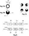
- a block diagram showing the different decoding steps is shown on the figure 8 . This diagram shows that step 70 comprises an operation 320 for decoding the data read on the marker, then an operation 310 of decoding the values of correction of the data then an operation 300 of verification of the integrity of the data.
- Step 70 may comprise, before the decoding of the information, a so-called inverse homographic transformation to retro-project the image onto the Real plane.
- Standard interpolation techniques can be used in case of image dilation.
- the image obtained can also be standardized to promote the reading of the coded data.
- coding may be used to encode the marker data of the invention. Whatever the type of coding used, a piece of data is encoded according to the operations of the block diagram represented on the figure 8 an operation 200 for applying integrity to the data is first performed, then an operation 210 for coding the correction data, and then an operation 220 for coding the data itself. Once coded, the data can be applied to the marker.
- the coding may be a coding specific to the marker of the invention or, on the contrary, a non-specific coding and used for other markers.
- the data contained in the marker can also be encoded by the components of an image.
- each data item is encoded as dots or points clusters whose binary value is represented by a color or a gray level.
- An example of a marker in which the data is coded in luminance is the Barrel code, represented on the Figure 6A .
- the information is carried by a value of the luminance at the center of the circles: some data are coded by white dots 121 in the center of a gray circle 123; other data are coded by gray dots 122 inside a white circle 124.
- Another example of a marker comprising data coded according to the Barrel code is represented on the Figure 6B .
- the step 70 of the method of the invention may comprise an additional operation of thresholding the image, this thresholding providing an optimal reading of the dominant luminance at the center of the circles.
- 24-bit binary information can then be extracted and decoded and / or corrected by an error-correcting code calculation function of the Golay, BCH or Reed Solomon type.
- the information obtained at the output of the decoding algorithm is then corrected information.
- some geometric signature encodings such as the bar code, shown in FIG. Figure 6C .
- encodings by geometric signatures can be, for example, an encoding by off-center circles, also called Necklace encoding, or a centered circles coding, called Flower encoding.
- the coded data is formed of a set of conics.
- the encoded data may be circles, centered or off-center with respect to each other, as shown on the figures 6 .
- each digital data is coded by means of two off-center circles, or off-center disks, forming a coding element 130.
- This coding element 130 comprises a gray disc 131 of radius R and a white disk 132 of radius R / 2.
- the white disk 132 is placed inside a gray circle 131, off-center with respect to said gray disk 131.
- the location of the white disk in the gray disk determines the binary value of the coding element. Examples of binary values of the coding elements are represented on the Figure 7C , described in more detail later.
- the coding element 130 may also have different dimensions, the size of this coding element determining the redundancy bits for data protection.
- the coding pattern is composed of at most 6 coding elements 130 placed around, or inside, the positioning contour 100 of the marker.
- An example of such a positioning contour is shown on the Figure 7A .
- this positioning contour 100 has an outer circle 100a and an inner circle 100b, concentric.
- the outer circle 100a may have a diameter of 60 relative units and the inner circle 100b a diameter of 45 relative units.
- the pattern M i is inserted counterclockwise after M i -1 around or within the positioning contour of the marker.
- Such off-center coding has the advantage of coding 24-bit data with 12 useful bits, which allows 4096-word coding.
- the Figures 6D and 6E show two examples of coding by eccentric circles according to the invention.
- the coding elements 130 previously described are distributed around the positioning contour 100.
- the coding elements 130 are distributed inside the positioning contour 100.
- the Figure 6H represents an example of centered circles coding.
- the data is encoded by sets of one or more different gray scale circles, for example gray circles and white circles, centered one inside the other and forming coding elements 140.
- These coding elements 140 are distributed in a positioning contour 100.
- the coding elements are placed around the positioning contour.
- the polarizing element is formed by two openings 150 in the positioning contour, facing one another.
- the coded data are decoded by applying a decoding algorithm depending on the type of coding used.
- a decoding algorithm depending on the type of coding used. For example, data encoded by geometric signatures will be decoded by applying a geometric signature decoding algorithm.
- the digital data contained in the marker are decoded and therefore readable.
- This digital data can then be used directly. They can also be used to search for information associated with this data. As previously explained, this information, referenced 80 on the figure 3 , can be searched in a database, using as a link, the decoded digital data.
- the decoded digital data may be associated with a person's identity information, item price, GPS location, etc.
- a marker according to the invention is generated by choosing, in a family of coplanar conics, a form of positioning contour of the marker and then determining a polarizing element and inserting this polarizing element in the marker.
- a type of coding must then be chosen to code the digital data in a deterministic and unambiguous manner.
- the digital data as well as the redundancy bits are then coded and placed around the positioning contour, or within said contour, according to the chosen coding. This placement of the coding elements can be done in a random or custom arrangement (as in the case of off-center coding).
- the method of generating the marker according to the invention makes it possible to obtain markers having a visually pleasing graphical presentation. Accordingly, the marker of the invention can be installed in visible locations such as billboards, logos, badges, etc. The aesthetics of the marker of the invention thus offers an important choice of applications.
- this marker being easy to detect whatever the environmental conditions, it can be positioned at a distance from the reader terminal. For example, a marker 5 cm in diameter can be detected and read at a distance of the order of 4 m; a marker 30 cm in diameter can be detected and read at a distance of the order of 10 to 12 m.
- a marker according to the invention can be used, for example, to sign or tag objects or points of interest, for example in a museum, and provide services or information associated with these objects or points of interest . It can also be used to provide absolute positioning reference points, for example, for a function of geolocated navigation. It can also serve as a relative positioning reference point, for example, for superimposing virtual 3D information on actual elements filmed and displayed on a screen.
Landscapes
- Engineering & Computer Science (AREA)
- Physics & Mathematics (AREA)
- Theoretical Computer Science (AREA)
- General Physics & Mathematics (AREA)
- General Health & Medical Sciences (AREA)
- Toxicology (AREA)
- Artificial Intelligence (AREA)
- Computer Vision & Pattern Recognition (AREA)
- Electromagnetism (AREA)
- Health & Medical Sciences (AREA)
- Image Analysis (AREA)
- Image Processing (AREA)
- Length Measuring Devices By Optical Means (AREA)
Claims (12)
- Verfahren für das Erfassen eines auf einer Oberfläche eines Objektes aufgebrachten Markers, dadurch gekennzeichnet, dass es die folgenden Vorgänge aufweist:a) Erwerben (40) eines photographischen Bildes (10) einer Szene, die mindestens einen Marker (11) enthält;b) Lesen des photographischen Bildes und Erfassen (50) des Markers in der Szene, wobei dieses Erfassen des Markers Folgendes aufweist:c) ein Extrahieren von Konturen aus dem photographischen Bild undd) ein Erfassen unter diesen Konturen von einer Kontur der Positionierung des Markers, die einer Anordnung von koplanaren Kegelschnitten von vorbestimmter Form entspricht,e) Lokalisieren (60) der Kontur der Positionierung des Markers, umfassend:f) ein Modellieren eines Bildes der koplanaren Kegelschnitte in einer Matrixform, wobei jeder Kegelschnitt durch eine symmetrische Matrix der Ordnung 3 dargestellt wird,g) ein Analysieren dieser Matrizen, um eine Korrektur der Perspektive des photographischen Bildes zu bestimmen,h) ein Erfassen in dem perspektivisch korrigierten photographischen Bild eines Unverwechselbarkeitselementes, das der Kontur der Positionierung des Markers graphisch zugeordnet ist, und Rotationskorrektur des photographischen Bildes,i) Erfassen in dem perspektivisch korrigierten und rotationskorrigierten photographischen Bild von codierten Daten, die der Kontur der Positionierung des Markers graphisch zugeordnet sind, und Decodieren (70) dieser codierten Daten.
- Verfahren für das Erfassen nach Anspruch 1, dadurch gekennzeichnet, dass sich die codierten Daten im Inneren der Kontur der Positionierung des Markers befinden.
- Verfahren für das Erfassen nach Anspruch 1, dadurch gekennzeichnet, dass sich die codierten Daten um die Kontur der Positionierung des Markers herum befinden.
- Verfahren für das Erfassen nach einem der Ansprüche 1 bis 3, dadurch gekennzeichnet, dass die Kontur der Positionierung des Markers aus einer Anordnung von konfokalen Kegelschnitten gebildet wird.
- Verfahren für das Erfassen nach einem der Ansprüche 1 bis 3, dadurch gekennzeichnet, dass die Kontur der Positionierung des Markers aus einer Anordnung von koplanaren Kreisen gebildet wird.
- Verfahren für das Erfassen nach einem der Ansprüche 1 bis 4, dadurch gekennzeichnet, dass die Kontur der Positionierung des Markers aus einer Anordnung (100) von zwei konzentrischen Kreisen (100a, 100b) gebildet wird.
- Verfahren für das Erfassen nach einem der Ansprüche 1 bis 6, dadurch gekennzeichnet, dass das Decodieren der codierten Daten das Anwenden eines Algorithmus der Luminanz- oder Chrominanzdecodierung aufweist.
- Verfahren für das Erfassen nach einem der Ansprüche 1 bis 6, dadurch gekennzeichnet, dass das Decodieren der codierten Daten das Anwenden eines Algorithmus der Decodierung durch geometrische Signaturen aufweist.
- Verfahren für das Erfassen nach einem der Ansprüche 1 bis 8, dadurch gekennzeichnet, dass das Decodieren der codierten Daten ein Suchen in einer Datenbank (30) von Informationen, die den decodierten Daten zugeordnet sind, aufweist.
- Verfahren für das Erfassen nach einem der Ansprüche 1 bis 9, dadurch gekennzeichnet, dass die codierten Daten aus einer Anordnung von Kegelschnitten gebildet werden.
- System für das Erfassen eines auf einer Oberfläche eines Objektes aufgebrachten Markers, dadurch gekennzeichnet, dass es ein Leseendgerät (20) aufweist, umfassend:- eine Bildaufnahmevorrichtung (21), die geeignet ist, ein photographisches Bild einer Szene zu erstellen, die mindestens einen Marker enthält, und- eine Verarbeitungseinheit (22) des photographischen Bildes, die geeignet ist, das Verfahren von Anspruch 1 umzusetzen, indem eine Kontur der Positionierung des Markers in dem photographischen Bild erfasst wird, indem diese Kontur der Positionierung lokalisiert wird, um eine Perspektiv- und eine Rotationskorrektur des photographischen Bildes vorzunehmen, und indem die codierten Daten, die dem Marker zugeordnet sind, decodiert werden.
- System nach Anspruch 11, dadurch gekennzeichnet, dass es eine Datenbank (30) aufweist, die in Verbindung mit dem Leseendgerät ist und Informationen enthält, die den codierten Daten zugeordnet sind, die in dem Marker enthalten sind.
Applications Claiming Priority (2)
| Application Number | Priority Date | Filing Date | Title |
|---|---|---|---|
| FR1060340A FR2968796B1 (fr) | 2010-12-10 | 2010-12-10 | Procede de detection d'un marqueur appose sur la surface d'un objet et systeme de mise en oeuvre |
| PCT/FR2011/052932 WO2012076828A2 (fr) | 2010-12-10 | 2011-12-09 | Procédé de détection d'un marqueur apposé sur la surface d'un objet et système de mise en oeuvre |
Publications (2)
| Publication Number | Publication Date |
|---|---|
| EP2649560A2 EP2649560A2 (de) | 2013-10-16 |
| EP2649560B1 true EP2649560B1 (de) | 2017-09-06 |
Family
ID=44247019
Family Applications (1)
| Application Number | Title | Priority Date | Filing Date |
|---|---|---|---|
| EP11811076.6A Active EP2649560B1 (de) | 2010-12-10 | 2011-12-09 | Verfahren für den nachweis eines an der oberfläche eines objektes fixierten markers und system zur umsetzung des verfahrens |
Country Status (7)
| Country | Link |
|---|---|
| US (1) | US8919649B2 (de) |
| EP (1) | EP2649560B1 (de) |
| DK (1) | DK2649560T3 (de) |
| ES (1) | ES2649573T3 (de) |
| FR (1) | FR2968796B1 (de) |
| NO (1) | NO2649560T3 (de) |
| WO (1) | WO2012076828A2 (de) |
Families Citing this family (6)
| Publication number | Priority date | Publication date | Assignee | Title |
|---|---|---|---|---|
| US9070019B2 (en) * | 2012-01-17 | 2015-06-30 | Leap Motion, Inc. | Systems and methods for capturing motion in three-dimensional space |
| GB201314642D0 (en) * | 2013-08-15 | 2013-10-02 | Summerfield Gideon | Image Identification System and Method |
| WO2015047400A1 (en) * | 2013-09-30 | 2015-04-02 | Hewlett-Packard Development Company, L.P. | Encoding information in a graphical element of an image |
| FR3055997A1 (fr) * | 2016-09-13 | 2018-03-16 | Alexandre Delattre | Systeme pour la determination d'au moins une caracteristique relative au contour d'un sujet contenu dans au moins une image numerique |
| JP2018134687A (ja) * | 2017-02-20 | 2018-08-30 | 大日本印刷株式会社 | ロボット、プログラム及びマーカ |
| US20190299878A1 (en) * | 2018-03-30 | 2019-10-03 | AISIN Technical Center of America, Inc. | Rear view camera system |
Family Cites Families (3)
| Publication number | Priority date | Publication date | Assignee | Title |
|---|---|---|---|---|
| DE60118051T2 (de) | 2000-04-06 | 2006-08-31 | Seiko Epson Corp. | Verfahren und Vorrichtung zum Lesen von einem zwei-dimensionalen Strichkode und Datenspeichermedium |
| DE10308383A1 (de) * | 2003-02-27 | 2004-09-16 | Storz Endoskop Produktions Gmbh | Verfahren und optisches System zur Vermessung der Topographie eines Meßobjekts |
| US8544736B2 (en) * | 2007-07-24 | 2013-10-01 | International Business Machines Corporation | Item scanning system |
-
2010
- 2010-12-10 FR FR1060340A patent/FR2968796B1/fr active Active
-
2011
- 2011-12-09 ES ES11811076.6T patent/ES2649573T3/es active Active
- 2011-12-09 EP EP11811076.6A patent/EP2649560B1/de active Active
- 2011-12-09 NO NO11811076A patent/NO2649560T3/no unknown
- 2011-12-09 WO PCT/FR2011/052932 patent/WO2012076828A2/fr not_active Ceased
- 2011-12-09 DK DK11811076.6T patent/DK2649560T3/en active
- 2011-12-09 US US13/992,820 patent/US8919649B2/en active Active
Non-Patent Citations (1)
| Title |
|---|
| None * |
Also Published As
| Publication number | Publication date |
|---|---|
| DK2649560T3 (en) | 2017-12-11 |
| FR2968796A1 (fr) | 2012-06-15 |
| WO2012076828A2 (fr) | 2012-06-14 |
| NO2649560T3 (de) | 2018-02-03 |
| ES2649573T3 (es) | 2018-01-12 |
| FR2968796B1 (fr) | 2014-04-25 |
| US8919649B2 (en) | 2014-12-30 |
| EP2649560A2 (de) | 2013-10-16 |
| WO2012076828A3 (fr) | 2012-08-02 |
| US20140008436A1 (en) | 2014-01-09 |
Similar Documents
| Publication | Publication Date | Title |
|---|---|---|
| EP2649560B1 (de) | Verfahren für den nachweis eines an der oberfläche eines objektes fixierten markers und system zur umsetzung des verfahrens | |
| CN109791623B (zh) | 具有包括物理表面的基底的制品及其构造方法 | |
| KR102427514B1 (ko) | 머신 판독 물품들을 위한 폐색 탄성 광학 코드들 | |
| Bergamasco et al. | Rune-tag: A high accuracy fiducial marker with strong occlusion resilience | |
| JP6162225B2 (ja) | 能動奥行き検知のためのアフィン不変空間マスクの送信 | |
| EP1554541A2 (de) | Kodiertes zielelement und ein photogrammetrie-verfahren das von solchen elementen gebrauch macht | |
| US20160321529A1 (en) | Producing, capturing and using visual identification tags for moving objects | |
| EP3304047B1 (de) | Verfahren zur verarbeitung von bildern mit glanz und entsprechendes computerprogrammprodukt | |
| FR2894685A1 (fr) | Procede et dispositif d'identification et de calibration d'optiques panoramiques | |
| EP2141656A1 (de) | Verfahren und Vorrichtung zur Echtzeiterkennung von Interaktionen zwischen einem Benutzer und einer Szene mit erweiterter Realität | |
| FR2968797A1 (fr) | Procede de generation d'un marqueur a apposer sur la surface d'un objet | |
| EP3291141B1 (de) | Verfahren zur erkennung von reliefartig hervorstehenden zeichen, entsprechendes computerprogrammprodukt und entsprechende vorrichtung | |
| FR2952218A1 (fr) | Procede et dispositif pour obtenir une image d'un document defroisse a partir d'une image de ce document lorsqu'il est froisse. | |
| CA2908210A1 (fr) | Procede d'identification d'un signe sur un document deforme | |
| Tang et al. | Three-dimensional surface reconstruction via a robust binary shape-coded structured light method | |
| EP3234914A1 (de) | Verfahren zur unterscheidung und identifizierung von objekten einer szene durch 3d-bildgebung | |
| CN107613239A (zh) | 视频通信背景显示方法和装置 | |
| US20150370348A1 (en) | Active triangulation calibration | |
| FR3095286A1 (fr) | Procédé de traitement d’image d’un document d’identité. | |
| Bergamasco et al. | Image-space marker detection and recognition using projective invariants | |
| FR3088160A1 (fr) | Capteur d'image pour la reconnaissance optique de code(s) | |
| EP3655889B1 (de) | Verfahren zur optischen authentifizierung | |
| EP2877979B1 (de) | Monokameraverfahren zur richtungsbestimmung eines festkörpers | |
| FR3129759A1 (fr) | Procédé d’aide au positionnement d’un objet par rapport à une zone cible d’une matrice de pixels d’une caméra, dispositif et programme d’ordinateur correspondants | |
| FR2797335A1 (fr) | Procede, support d'enregistrement et systeme informatique pour la reconnaissance de formes numerisees |
Legal Events
| Date | Code | Title | Description |
|---|---|---|---|
| PUAI | Public reference made under article 153(3) epc to a published international application that has entered the european phase |
Free format text: ORIGINAL CODE: 0009012 |
|
| 17P | Request for examination filed |
Effective date: 20130607 |
|
| AK | Designated contracting states |
Kind code of ref document: A2 Designated state(s): AL AT BE BG CH CY CZ DE DK EE ES FI FR GB GR HR HU IE IS IT LI LT LU LV MC MK MT NL NO PL PT RO RS SE SI SK SM TR |
|
| DAX | Request for extension of the european patent (deleted) | ||
| GRAP | Despatch of communication of intention to grant a patent |
Free format text: ORIGINAL CODE: EPIDOSNIGR1 |
|
| INTG | Intention to grant announced |
Effective date: 20170410 |
|
| RIN1 | Information on inventor provided before grant (corrected) |
Inventor name: CHARVILLAT, VINCENT Inventor name: GURDJOS, PIERRE Inventor name: BOURY, SAMUEL Inventor name: MEZZAROBBA, OLIVIER |
|
| GRAS | Grant fee paid |
Free format text: ORIGINAL CODE: EPIDOSNIGR3 |
|
| GRAA | (expected) grant |
Free format text: ORIGINAL CODE: 0009210 |
|
| AK | Designated contracting states |
Kind code of ref document: B1 Designated state(s): AL AT BE BG CH CY CZ DE DK EE ES FI FR GB GR HR HU IE IS IT LI LT LU LV MC MK MT NL NO PL PT RO RS SE SI SK SM TR |
|
| REG | Reference to a national code |
Ref country code: GB Ref legal event code: FG4D Free format text: NOT ENGLISH |
|
| REG | Reference to a national code |
Ref country code: CH Ref legal event code: EP Ref country code: AT Ref legal event code: REF Ref document number: 926602 Country of ref document: AT Kind code of ref document: T Effective date: 20170915 |
|
| REG | Reference to a national code |
Ref country code: IE Ref legal event code: FG4D Free format text: LANGUAGE OF EP DOCUMENT: FRENCH |
|
| REG | Reference to a national code |
Ref country code: DE Ref legal event code: R096 Ref document number: 602011041408 Country of ref document: DE |
|
| REG | Reference to a national code |
Ref country code: DK Ref legal event code: T3 Effective date: 20171206 |
|
| REG | Reference to a national code |
Ref country code: SE Ref legal event code: TRGR |
|
| REG | Reference to a national code |
Ref country code: NL Ref legal event code: FP |
|
| REG | Reference to a national code |
Ref country code: FR Ref legal event code: PLFP Year of fee payment: 7 |
|
| REG | Reference to a national code |
Ref country code: ES Ref legal event code: FG2A Ref document number: 2649573 Country of ref document: ES Kind code of ref document: T3 Effective date: 20180112 |
|
| REG | Reference to a national code |
Ref country code: LT Ref legal event code: MG4D |
|
| PG25 | Lapsed in a contracting state [announced via postgrant information from national office to epo] |
Ref country code: HR Free format text: LAPSE BECAUSE OF FAILURE TO SUBMIT A TRANSLATION OF THE DESCRIPTION OR TO PAY THE FEE WITHIN THE PRESCRIBED TIME-LIMIT Effective date: 20170906 Ref country code: LT Free format text: LAPSE BECAUSE OF FAILURE TO SUBMIT A TRANSLATION OF THE DESCRIPTION OR TO PAY THE FEE WITHIN THE PRESCRIBED TIME-LIMIT Effective date: 20170906 Ref country code: FI Free format text: LAPSE BECAUSE OF FAILURE TO SUBMIT A TRANSLATION OF THE DESCRIPTION OR TO PAY THE FEE WITHIN THE PRESCRIBED TIME-LIMIT Effective date: 20170906 |
|
| REG | Reference to a national code |
Ref country code: NO Ref legal event code: T2 Effective date: 20170906 |
|
| REG | Reference to a national code |
Ref country code: AT Ref legal event code: MK05 Ref document number: 926602 Country of ref document: AT Kind code of ref document: T Effective date: 20170906 |
|
| PG25 | Lapsed in a contracting state [announced via postgrant information from national office to epo] |
Ref country code: LV Free format text: LAPSE BECAUSE OF FAILURE TO SUBMIT A TRANSLATION OF THE DESCRIPTION OR TO PAY THE FEE WITHIN THE PRESCRIBED TIME-LIMIT Effective date: 20170906 Ref country code: BG Free format text: LAPSE BECAUSE OF FAILURE TO SUBMIT A TRANSLATION OF THE DESCRIPTION OR TO PAY THE FEE WITHIN THE PRESCRIBED TIME-LIMIT Effective date: 20171206 Ref country code: RS Free format text: LAPSE BECAUSE OF FAILURE TO SUBMIT A TRANSLATION OF THE DESCRIPTION OR TO PAY THE FEE WITHIN THE PRESCRIBED TIME-LIMIT Effective date: 20170906 |
|
| PG25 | Lapsed in a contracting state [announced via postgrant information from national office to epo] |
Ref country code: PL Free format text: LAPSE BECAUSE OF FAILURE TO SUBMIT A TRANSLATION OF THE DESCRIPTION OR TO PAY THE FEE WITHIN THE PRESCRIBED TIME-LIMIT Effective date: 20170906 Ref country code: RO Free format text: LAPSE BECAUSE OF FAILURE TO SUBMIT A TRANSLATION OF THE DESCRIPTION OR TO PAY THE FEE WITHIN THE PRESCRIBED TIME-LIMIT Effective date: 20170906 Ref country code: CZ Free format text: LAPSE BECAUSE OF FAILURE TO SUBMIT A TRANSLATION OF THE DESCRIPTION OR TO PAY THE FEE WITHIN THE PRESCRIBED TIME-LIMIT Effective date: 20170906 |
|
| PG25 | Lapsed in a contracting state [announced via postgrant information from national office to epo] |
Ref country code: SK Free format text: LAPSE BECAUSE OF FAILURE TO SUBMIT A TRANSLATION OF THE DESCRIPTION OR TO PAY THE FEE WITHIN THE PRESCRIBED TIME-LIMIT Effective date: 20170906 Ref country code: EE Free format text: LAPSE BECAUSE OF FAILURE TO SUBMIT A TRANSLATION OF THE DESCRIPTION OR TO PAY THE FEE WITHIN THE PRESCRIBED TIME-LIMIT Effective date: 20170906 Ref country code: SM Free format text: LAPSE BECAUSE OF FAILURE TO SUBMIT A TRANSLATION OF THE DESCRIPTION OR TO PAY THE FEE WITHIN THE PRESCRIBED TIME-LIMIT Effective date: 20170906 Ref country code: IS Free format text: LAPSE BECAUSE OF FAILURE TO SUBMIT A TRANSLATION OF THE DESCRIPTION OR TO PAY THE FEE WITHIN THE PRESCRIBED TIME-LIMIT Effective date: 20180106 Ref country code: AT Free format text: LAPSE BECAUSE OF FAILURE TO SUBMIT A TRANSLATION OF THE DESCRIPTION OR TO PAY THE FEE WITHIN THE PRESCRIBED TIME-LIMIT Effective date: 20170906 |
|
| REG | Reference to a national code |
Ref country code: DE Ref legal event code: R097 Ref document number: 602011041408 Country of ref document: DE |
|
| PLBE | No opposition filed within time limit |
Free format text: ORIGINAL CODE: 0009261 |
|
| STAA | Information on the status of an ep patent application or granted ep patent |
Free format text: STATUS: NO OPPOSITION FILED WITHIN TIME LIMIT |
|
| 26N | No opposition filed |
Effective date: 20180607 |
|
| PG25 | Lapsed in a contracting state [announced via postgrant information from national office to epo] |
Ref country code: SI Free format text: LAPSE BECAUSE OF FAILURE TO SUBMIT A TRANSLATION OF THE DESCRIPTION OR TO PAY THE FEE WITHIN THE PRESCRIBED TIME-LIMIT Effective date: 20170906 |
|
| REG | Reference to a national code |
Ref country code: IE Ref legal event code: MM4A |
|
| PG25 | Lapsed in a contracting state [announced via postgrant information from national office to epo] |
Ref country code: MT Free format text: LAPSE BECAUSE OF FAILURE TO SUBMIT A TRANSLATION OF THE DESCRIPTION OR TO PAY THE FEE WITHIN THE PRESCRIBED TIME-LIMIT Effective date: 20170906 Ref country code: LU Free format text: LAPSE BECAUSE OF NON-PAYMENT OF DUE FEES Effective date: 20171209 |
|
| PG25 | Lapsed in a contracting state [announced via postgrant information from national office to epo] |
Ref country code: IE Free format text: LAPSE BECAUSE OF NON-PAYMENT OF DUE FEES Effective date: 20171209 |
|
| PG25 | Lapsed in a contracting state [announced via postgrant information from national office to epo] |
Ref country code: MC Free format text: LAPSE BECAUSE OF FAILURE TO SUBMIT A TRANSLATION OF THE DESCRIPTION OR TO PAY THE FEE WITHIN THE PRESCRIBED TIME-LIMIT Effective date: 20170906 Ref country code: HU Free format text: LAPSE BECAUSE OF FAILURE TO SUBMIT A TRANSLATION OF THE DESCRIPTION OR TO PAY THE FEE WITHIN THE PRESCRIBED TIME-LIMIT; INVALID AB INITIO Effective date: 20111209 |
|
| PG25 | Lapsed in a contracting state [announced via postgrant information from national office to epo] |
Ref country code: CY Free format text: LAPSE BECAUSE OF NON-PAYMENT OF DUE FEES Effective date: 20170906 |
|
| PG25 | Lapsed in a contracting state [announced via postgrant information from national office to epo] |
Ref country code: MK Free format text: LAPSE BECAUSE OF FAILURE TO SUBMIT A TRANSLATION OF THE DESCRIPTION OR TO PAY THE FEE WITHIN THE PRESCRIBED TIME-LIMIT Effective date: 20170906 |
|
| PG25 | Lapsed in a contracting state [announced via postgrant information from national office to epo] |
Ref country code: TR Free format text: LAPSE BECAUSE OF FAILURE TO SUBMIT A TRANSLATION OF THE DESCRIPTION OR TO PAY THE FEE WITHIN THE PRESCRIBED TIME-LIMIT Effective date: 20170906 |
|
| PG25 | Lapsed in a contracting state [announced via postgrant information from national office to epo] |
Ref country code: PT Free format text: LAPSE BECAUSE OF FAILURE TO SUBMIT A TRANSLATION OF THE DESCRIPTION OR TO PAY THE FEE WITHIN THE PRESCRIBED TIME-LIMIT Effective date: 20170906 |
|
| PG25 | Lapsed in a contracting state [announced via postgrant information from national office to epo] |
Ref country code: GR Free format text: LAPSE BECAUSE OF FAILURE TO SUBMIT A TRANSLATION OF THE DESCRIPTION OR TO PAY THE FEE WITHIN THE PRESCRIBED TIME-LIMIT Effective date: 20170906 |
|
| PG25 | Lapsed in a contracting state [announced via postgrant information from national office to epo] |
Ref country code: AL Free format text: LAPSE BECAUSE OF FAILURE TO SUBMIT A TRANSLATION OF THE DESCRIPTION OR TO PAY THE FEE WITHIN THE PRESCRIBED TIME-LIMIT Effective date: 20170906 |
|
| PGFP | Annual fee paid to national office [announced via postgrant information from national office to epo] |
Ref country code: NL Payment date: 20241227 Year of fee payment: 14 |
|
| PGFP | Annual fee paid to national office [announced via postgrant information from national office to epo] |
Ref country code: GB Payment date: 20241230 Year of fee payment: 14 |
|
| PGFP | Annual fee paid to national office [announced via postgrant information from national office to epo] |
Ref country code: FR Payment date: 20241230 Year of fee payment: 14 |
|
| PGFP | Annual fee paid to national office [announced via postgrant information from national office to epo] |
Ref country code: DE Payment date: 20241227 Year of fee payment: 14 |
|
| PGFP | Annual fee paid to national office [announced via postgrant information from national office to epo] |
Ref country code: ES Payment date: 20250109 Year of fee payment: 14 |
|
| PGFP | Annual fee paid to national office [announced via postgrant information from national office to epo] |
Ref country code: SE Payment date: 20241230 Year of fee payment: 14 |
|
| PGFP | Annual fee paid to national office [announced via postgrant information from national office to epo] |
Ref country code: BE Payment date: 20241224 Year of fee payment: 14 |
|
| PGFP | Annual fee paid to national office [announced via postgrant information from national office to epo] |
Ref country code: IT Payment date: 20241227 Year of fee payment: 14 |
|
| REG | Reference to a national code |
Ref country code: CH Ref legal event code: U11 Free format text: ST27 STATUS EVENT CODE: U-0-0-U10-U11 (AS PROVIDED BY THE NATIONAL OFFICE) Effective date: 20260108 |
|
| PGFP | Annual fee paid to national office [announced via postgrant information from national office to epo] |
Ref country code: NO Payment date: 20251229 Year of fee payment: 15 |
|
| PGFP | Annual fee paid to national office [announced via postgrant information from national office to epo] |
Ref country code: DK Payment date: 20251229 Year of fee payment: 15 |
|
| PGFP | Annual fee paid to national office [announced via postgrant information from national office to epo] |
Ref country code: CH Payment date: 20260108 Year of fee payment: 15 |