EP2651143B1 - Bildprojektor - Google Patents
Bildprojektor Download PDFInfo
- Publication number
- EP2651143B1 EP2651143B1 EP13001851.8A EP13001851A EP2651143B1 EP 2651143 B1 EP2651143 B1 EP 2651143B1 EP 13001851 A EP13001851 A EP 13001851A EP 2651143 B1 EP2651143 B1 EP 2651143B1
- Authority
- EP
- European Patent Office
- Prior art keywords
- projection apparatus
- light bundle
- light
- image projection
- path
- Prior art date
- Legal status (The legal status is an assumption and is not a legal conclusion. Google has not performed a legal analysis and makes no representation as to the accuracy of the status listed.)
- Active
Links
Images


Classifications
-
- G—PHYSICS
- G02—OPTICS
- G02B—OPTICAL ELEMENTS, SYSTEMS OR APPARATUS
- G02B30/00—Optical systems or apparatus for producing three-dimensional [3D] effects, e.g. stereoscopic images
- G02B30/20—Optical systems or apparatus for producing three-dimensional [3D] effects, e.g. stereoscopic images by providing first and second parallax images to an observer's left and right eyes
- G02B30/22—Optical systems or apparatus for producing three-dimensional [3D] effects, e.g. stereoscopic images by providing first and second parallax images to an observer's left and right eyes of the stereoscopic type
- G02B30/25—Optical systems or apparatus for producing three-dimensional [3D] effects, e.g. stereoscopic images by providing first and second parallax images to an observer's left and right eyes of the stereoscopic type using polarisation techniques
-
- G—PHYSICS
- G03—PHOTOGRAPHY; CINEMATOGRAPHY; ANALOGOUS TECHNIQUES USING WAVES OTHER THAN OPTICAL WAVES; ELECTROGRAPHY; HOLOGRAPHY
- G03B—APPARATUS OR ARRANGEMENTS FOR TAKING PHOTOGRAPHS OR FOR PROJECTING OR VIEWING THEM; APPARATUS OR ARRANGEMENTS EMPLOYING ANALOGOUS TECHNIQUES USING WAVES OTHER THAN OPTICAL WAVES; ACCESSORIES THEREFOR
- G03B21/00—Projectors or projection-type viewers; Accessories therefor
- G03B21/14—Details
- G03B21/20—Lamp housings
- G03B21/2073—Polarisers in the lamp house
-
- G—PHYSICS
- G03—PHOTOGRAPHY; CINEMATOGRAPHY; ANALOGOUS TECHNIQUES USING WAVES OTHER THAN OPTICAL WAVES; ELECTROGRAPHY; HOLOGRAPHY
- G03B—APPARATUS OR ARRANGEMENTS FOR TAKING PHOTOGRAPHS OR FOR PROJECTING OR VIEWING THEM; APPARATUS OR ARRANGEMENTS EMPLOYING ANALOGOUS TECHNIQUES USING WAVES OTHER THAN OPTICAL WAVES; ACCESSORIES THEREFOR
- G03B35/00—Stereoscopic photography
-
- H—ELECTRICITY
- H04—ELECTRIC COMMUNICATION TECHNIQUE
- H04N—PICTORIAL COMMUNICATION, e.g. TELEVISION
- H04N13/00—Stereoscopic video systems; Multi-view video systems; Details thereof
- H04N13/30—Image reproducers
- H04N13/332—Displays for viewing with the aid of special glasses or head-mounted displays [HMD]
- H04N13/337—Displays for viewing with the aid of special glasses or head-mounted displays [HMD] using polarisation multiplexing
-
- H—ELECTRICITY
- H04—ELECTRIC COMMUNICATION TECHNIQUE
- H04N—PICTORIAL COMMUNICATION, e.g. TELEVISION
- H04N13/00—Stereoscopic video systems; Multi-view video systems; Details thereof
- H04N13/30—Image reproducers
- H04N13/332—Displays for viewing with the aid of special glasses or head-mounted displays [HMD]
- H04N13/341—Displays for viewing with the aid of special glasses or head-mounted displays [HMD] using temporal multiplexing
-
- H—ELECTRICITY
- H04—ELECTRIC COMMUNICATION TECHNIQUE
- H04N—PICTORIAL COMMUNICATION, e.g. TELEVISION
- H04N13/00—Stereoscopic video systems; Multi-view video systems; Details thereof
- H04N13/30—Image reproducers
- H04N13/363—Image reproducers using image projection screens
Definitions
- the present disclosure relates to an image projection apparatus for magnifying and projecting a generated image to the outside.
- the image projection apparatus refers to an apparatus for implementing an image using light emitted from the light source, and projecting the implemented image, and the representative examples include a projector, a projection television, and the like.
- the method of implementing stereoscopic images in an image projection apparatus may be divided into two types.
- One is a shutter glass (SG) scheme which is a method of sequentially reproducing left and right eye images to implement a solid image through synchronized 3D glasses
- the other one is a film patterned retarder (FPR) scheme which is a method of generating a difference between left and right eye phases using a circular polarized shutter to recognize a stereoscopic image in human brain through polarized 3D glasses.
- SG shutter glass
- FPR film patterned retarder
- US 2010/253920 A1 relates to a projector optical system e.g. three plate type projector, that has polarized light emitting unit that is arranged at image forming position, to selectively convert the polarization direction of portion of entering light.
- a projector optical system e.g. three plate type projector, that has polarized light emitting unit that is arranged at image forming position, to selectively convert the polarization direction of portion of entering light.
- Light emitted from a light source enters a display panel of the projector optical system via illumination systems that include a second lens array.
- a polarization converting element disposed within the illumination systems polarizes light emitted from the second lens array.
- Figure 1 is a perspective view illustrating a display system 10 according to an embodiment of the present disclosure.
- the display system 10 may include an image projection apparatus 100 disposed to implement stereoscopic images, a screen unit 101, and a polarized glasses unit 102.
- the image projection apparatus 100 may be a projector or the like for magnifying and projecting an image as illustrated in the drawing.
- the image projection apparatus 100 associated with the present disclosure will be described on the basis of a projector.
- the image projection apparatus 100 may not only be limited to this, but also applicable to a projection apparatus integrated into a projection television, and the like, for example.
- the image projection apparatus 100 may be formed to project both a first and a second image 104a, 104b having different polarized directions 103a, 103b.
- the polarized lights having the different polarized directions may be referred to as a first and a second polarized light 103a, 103b, respectively.
- the first and the second polarized light 103a, 103b may be circular polarized lights rotated in different directions from each other, respectively.
- the first and the second image 104a, 104b may be formed to have binocular parallex forming stereoscopic images.
- the first and the second image 104a, 104b may be left and right eye images, respectively.
- the present disclosure may not only be limited to this, and the first and the second image 104a, 104b may be also right and left eye images, respectively.
- the screen unit 101 displays an image magnified and projected from the image projection apparatus 100 as a screen.
- the screen unit 101 is disposed at a location crossed with a projection direction of the image projection apparatus 100 on which the left and the right eye image 104a, 104b are projected.
- the screen unit 101 may be a wall surface, an achromatic or silver-colored film, or the like.
- the screen unit 101 may be a polarization maintaining screen formed to maintain a polarized state.
- the polarized glasses unit 102 is formed with polarizing plates corresponding to different circular polarized lights 103a, 103b, respectively.
- the left and the right eye image 104a, 104b having binocular parallex, respectively reach the user's left and right eyes. Accordingly, the user can view stereoscopic images.
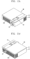
- Figures 2A and 2B are front and rear perspective views, respectively, illustrating an image projection apparatus in Figure 1 .
- a case (casing, housing, cover, etc.) constituting an external appearance of the body of the image projection apparatus 100 may be formed by an upper and a lower case 111, 112.
- Various optical elements and electronic elements are integrated into a space formed by the upper and the lower case 111, 112.
- a manipulation unit 113 or the like may be disposed at the upper case 111.
- the manipulation unit 113 may be formed to allow the user to enter a control command such as start, end, zoom-in, zoom-out, focusing, and the like, and any method can be employed if it is a tactile manner allowing the user to perform manipulation with a tactile feeling.
- a projection unit 114, a first and a second air flow unit 115a, 115b, an interface 116, and the like may be disposed at the lower case 112.
- the projection unit 114 may be formed to magnify an image projected from the image projection apparatus 100.
- the first and the second air flow unit 115a, 115b are made of a plurality of through holes such that air can flow into the image projection apparatus. Through this, it may be possible to implement the cooling of the image projection apparatus using forced convection.
- the interface 116 may be a path for allowing the image projection apparatus 100 to exchange data with external devices. Image data corresponding to an image to be projected from the image projection apparatus 100 may be received from the outside through the interface 116.
- the interface 116 may include a connection terminal that can be electrically connected to an electronic device, such as a computer, a DVD player, or the like, capable of supplying image or audio data.
- Figure 3 is an exploded view illustrating an image projection apparatus 100 in Figure 1
- Figure 4 is a conceptual view schematically illustrating an optical system in Figure 3 .
- a control circuit board 121 and a power board 122 may be mounted in the lower case 112.
- the control circuit board 12 may be configured as an example of the controller for operating various functions of the image projection apparatus 100.
- the power board 122 receives an alternating current power source or the like and converts it into a direct current power source required to drive the image projection apparatus 100.
- an optical system 130 arranged with optical elements such as lenses to form an image and project the image to the outside may be mounted in the lower case 112.
- a structure (not shown) into which the optical system 130 can be assembled may be additionally disposed between the optical system 130 and the lower case 112.
- the optical system 130 may include an optical source 131, a illumination system 140, a display element 132, and a projection system 133.
- the optical source 131 may be formed to generate light.
- the optical source 131 may be a ultra high voltage (UHV) lamp, a light emitting diode (LED), a laser diode (LD), and the like, for example.
- a stabilizer for stabilizing electricity supplied to the optical source 131, a cooling fan for generating forced convection, and the like may be mounted in the lower case 112 to assist the operation of the optical source 131.
- the illumination system 140 may be disposed adjacent to the optical source 131 to illuminate a light bundle generated from the optical source 131 in a predetermined direction.
- the illumination system 140 refers to a system in which optical elements such as lenses are disposed to form a group with a predetermined arrangement. Furthermore, the illumination system 140 is formed to sequentially convert the light bundle into circular polarized lights 103a, 103b (refer to Figure 1 ) having different rotational directions from each other. To this end, a polarization forming unit 142 is inserted and disposed between a plurality of lenses 141 of the illumination system. In this manner, the polarization forming unit 142 may be inserted into a space between lenses, and thus it may be possible to maintain the size of the optical system in a compact manner.
- the illumination system 140 may be a lens assembly.
- the display element 132 forms left and right eye images using circular polarized lights 103a, 103b. More specifically, the display element 132 may be controlled to reflect incident polarized light to form an image. Specifically, the display element 132 reflects a light bundle entered to correspond to left and right eye images to be implemented in an independent manner on a plurality of micro mirrors.
- the electronic element may be a digital micromirror device (DMD) in which micro mirrors whose tilt angles are changed to an ON or OFF state according to a control signal are arranged in a lattice structure on a plane, for example.
- the electronic element may be a liquid crystal on silicon (LCOS) panel that can reflect light to implement an image, among liquid crystal display devices.
- the display element 132 may be referred to as a display panel, display chip, display array, display device, or the like. Moreover, the display element 132 may include a plurality of display devices.
- the projection system 133 may be configured to magnify and project an image formed in the display element 132.
- the projection system 133 may form a projection unit 114 (refer to Figure 2A ) in which lenses and a structure for supporting the lenses are combined with each other.
- the projection unit 114 may include a projection lens.
- the illumination system 140 may be disposed between the optical source 131 and the display element 132 to perform the illumination and polarization of a light bundle.
- the illumination system will be described in more detail with reference to Figures 5 and 6 .
- Figure 5 is an enlarged view illustrating light advancement in the illumination system 140 in Figure 4
- Figure 6 is a conceptual view illustrating a configuration in which the polarization forming unit is moved in the illumination system in Figure 4
- Figures 7A and 7B are simulation results illustrating an optical performance and subsequent to the insertion of the polarization forming unit.
- the polarization forming unit 142 may also be referred to herein as a polarizing optical device or a polarizing lens.
- a plurality of lenses 141 are disposed to illuminate a light bundle generated from the light source to the display element 132. Furthermore, a light integrator 134 may be disposed between the plurality of lenses 141 and the optical source 131. The light integrator 134 is disposed at a location on which light reflected from the reflector of the optical source 131 is converged, and performs the role of allowing light to be uniformly distributed and advancing the uniformly distributed light into the plurality of lenses 141.
- the light integrator 134 may be a light tunnel, an integrator, or the like, and through this, the distribution of the light bundle luminance becomes uniform.
- a light bundle that has passed through the light integrator 134 is refracted again by the plurality of lenses 141 to match to the size of the display element 132.
- the plurality of lenses 141 are composed of concave and convex lenses to form a stop.
- the polarization forming unit 142 may be disposed between the plurality of lenses to convert the light bundle into polarized light in the illumination system 140 to implement stereoscopic images. More specifically, the polarization forming unit 142 may be formed to sequentially convert the light bundle into circular polarized lights in different directions from one another, and for such an example, the polarization forming unit 142 may include a circular polarized shutter with a film patterned retarder (FPR) scheme. However, the present disclosure may not only be limited to this, and the polarization forming unit 142 may be a linear polarized shutter.
- FPR film patterned retarder
- the polarization forming unit 142 is disposed at a location of the stop. If an incident angle of the stop is greater than 10 degrees, then the optical efficiency of a illumination system will be reduced by the polarization forming unit 142 located at the stop. According to the present disclosure, the incident angle of the stop may be formed within a range of 1 to 5.3 degrees to maintain the optical efficiency of the illumination system 140.
- the illumination system 140 may include a concave lens 143 disposed at a front side of the polarization forming unit 142 on the path of the light bundle to reduce an incident angle of the light bundle to the polarization forming unit 142.
- the concave lens 143 is disposed at a front side of the stop on the path of the light bundle such that any one of the plurality of lenses 141 is disposed adjacent to a front side of the polarization forming unit 142.
- Any one convex lens 144 of the plurality of lenses 141 may be disposed between the concave lens 143 and the polarization forming unit 142.
- an incident angle of the stop may be formed at 1 to 5.3 degrees.
- an optical system may be formed to implement two-dimensional images as well as stereoscopic images. More specifically, the polarization forming unit 142 may be formed in a movable manner, and thus inserted into or released from the location of the stop by the movement. In this manner, the polarization forming unit 142 can be moved, thereby obtaining an advantage that there is no optical efficiency reduction due to the use of the polarization forming unit 142 while viewing two-dimensional images.
- Figures 7A and 7B are simulation results for illumination shape prior to and subsequent to the insertion of a circular polarized shutter, respectively. Referring to the drawings, it is seen that a difference between their illumination shape and luminance prior to and subsequent to the insertion of the polarization forming unit 142 is a level of simulation error, and thus there is almost no difference. Accordingly, it may be possible to implement stereoscopic images without a dummy glass requiring additional cost and configuration space.
- the illumination system 140 may include a plurality of mirrors 145, 146 disposed adjacent to one another, and the plurality of mirrors 145, 146 are disposed between the polarization forming unit 142 and the display element 132.
- a prism 147 may be disposed adjacent to the display element. The prism 147 is formed to reflect or transmit a light bundle entered from an inner oblique side thereof, and through this, the light bundle reflected on the mirror 146 is refracted toward the display element 132, and an image formed at the display element 132 is transmitted to the projection system 133.
- the polarization forming unit 142 is disposed at an opposite side to the projection system 133 for magnifying and projecting the image by interposing a light bundle proceeding toward the plurality of mirrors 145, 146 during the implementation of two-dimensional images. Due to such a structure, polarized light formed at the polarization forming unit 142 is refracted by 180 degrees to enter the prism 147, and through this, it may be possible to configure a very compact optical system.
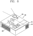
- Figure 8 is a perspective view illustrating an image projection apparatus according to another embodiment of the present disclosure.
- an optical system in Figure 5 may be applicable to the implementation of a ultra short throw (UST) ratio optical system for projecting a large-sized screen in a configuration located adjacent to the screen.
- the projection unit 214 may be formed to project an image from an upper surface of the upper case 211 to the outside.
- a light bundle exited from the projection system (not shown) is reflected on the mirror 234 toward the outside to implement a large-sized screen from a short distance at an end of the projection system (not shown).
- the mirror 234 is formed of a concave mirror.
- an image projection apparatus may include a light source configured to generate a light bundle, a lens assembly, and a display element configured to form an image using the light bundle, the lens assembly being provided in a path of the light bundle between the light source and the display element, wherein the lens assembly includes a plurality of lenses provided to advance the light bundle toward the display element, and a polarizing optical device provided between the plurality of lenses to convert the light bundle into polarized light for producing stereoscopic images.
- the plurality of lenses may include a concave lens provided on a path of the light bundle prior to the polarizing optical device to reduce an incident angle of the light bundle at the polarizing optical device.
- the plurality of lenses may include at least one convex lens disposed between the concave lens and the polarizing optical device.
- the plurality of lenses may be disposed to form a stop, and the concave lens may be provided on the path of the light bundle prior to the stop.
- the concave lens may be configured to form an incident angle at the stop to be about 1° to 5.3°.
- the polarizing optical device may be configured to be moved into a position corresponding to the stop.
- the polarizing optical device may be configured to be moved into a path of the light bundle.
- the polarizing optical device may be configured to slidably move into a path of the light bundle.
- the polarizing optical device may be configured to move in a direction perpendicular to the path of the light bundle.
- the polarizing optical device may include a circular polarized shutter with a film patterned retarder (FPR) scheme.
- the polarizing optical device may be formed to sequentially convert the light bundle into a circular polarized light in a first direction and a circular polarized light in a second direction that is different than the first direction.
- FPR film patterned retarder
- the image projection apparatus may further include a plurality of mirrors provided adjacent to one another, and provided along the path of the light bundle between the polarizing optical device and the display element.
- the plurality of mirrors may be configured to change the path of the light bundle by about 180°.
- a prism may be provided adjacent to the display element and configured to change the path of the light bundle by about 90°.
- a direction of the path of the light bundle after the prism can be about 90° relative to a direction of the path of the light bundle at the lens assembly.
- the image projection apparatus may further include a projection system that magnifies and projects the image, wherein the projection system and the polarizing optical device may be disposed at opposite sides of the plurality of mirrors.
- the projection system is configured to project the light bundle in a direction at a prescribed angle relative to a plane corresponding to the path of the light bundle through the lens assembly and the plurality of the mirrors.
- an image projection apparatus may include a light source that generates a light bundle in a first direction, a first lens provided in a path of the light bundle in the first direction, a polarizing lens provided after the first lens in the path of the light bundle in the first direction to convert the light bundle into polarized light for producing stereoscopic images, a second lens provided after the polarizing lens in the path of the light bundle in the first direction, a display device to generate an image for projection using the light bundle, and a third lens provided to project the light bundle from the display device, wherein the path of the light bundle at the display device is in a second direction different than the first direction.
- At least one mirror may be provided after the second lens to change a direction of the light bundle from the first direction to the second direction.
- a prism may be provided adjacent to the display device to change the direction of the light bundle from the second direction to a third direction which is different than the first and second directions.
- the polarizing lens may be configured to be movable into the path of the light bundle.
- an image projection apparatus may include a light source that generates a light bundle in a first direction, a plurality of lens provided in a path of the light bundle in the first direction, a display device provided in the path of the light bundle after the plurality of lens to generate an image for projection using the light bundle, a prism provided at the display device, and a projection lens provided in the path of the light bundle after the prism to project the light bundle from the display device, wherein the path of the light bundle at the display device is in a second direction different than the first direction.
- the polarization forming unit may be disposed between lens groups in a illumination system, thereby implementing stereoscopic images in a compact optical system. Furthermore, a concave lens may be disposed at a front side of the polarization forming unit, thereby limiting an incident angle of the light bundle entered into the polarization forming unit. Through this, it may be possible to prevent or alleviate optical efficiency reduction due to the polarization forming unit.
- a illumination system may use a plurality of mirrors disposed adjacent to one another, thereby securing a space for the movement of the polarization forming unit and restricting the size of an optical system.
Landscapes
- Engineering & Computer Science (AREA)
- Multimedia (AREA)
- Signal Processing (AREA)
- Physics & Mathematics (AREA)
- General Physics & Mathematics (AREA)
- Optics & Photonics (AREA)
- Testing, Inspecting, Measuring Of Stereoscopic Televisions And Televisions (AREA)
- Projection Apparatus (AREA)
- Stereoscopic And Panoramic Photography (AREA)
Claims (12)
- Bildprojektor umfassend:eine Lichtquelle (131), die zum Erzeugen eines Lichtbündels eingerichtet ist;ein Anzeigeelement (132), das eingerichtet ist, um unter Verwendung des Lichtbündels ein Bild zu bilden;eine Mehrzahl von Linsen (141), die vorgesehen sind, um das Lichtbündel in Richtung des Anzeigeelements zu befördern, wobei die Mehrzahl von Linsen (141) in einem Pfad des Lichtbündels zwischen der Lichtquelle und dem Anzeigeelement vorgesehen sind und eine konkave Linse und mindestens konvexe Linse umfasst, wobei die Mehrzahl von Linsen angeordnet sind, um eine Blende zu bilden, und die konkave Linse auf dem Pfad des Lichtbündels vor der Blende vorgesehen ist; undeine polarisierende optische Vorrichtung (142), die zwischen der Mehrzahl von Linsen vorgesehen ist, um das Lichtbündel sequenziell in zirkular polarisiertes Licht in voneinander verschiedenen Richtungen umzuwandeln, um stereoskopische Bilder zu erzeugen,dadurch gekennzeichnet, dass die polarisierende optische Vorrichtung an einer Position der Blende angeordnet ist, und wobei die mindestens eine konvexe Linse zwischen der konkaven Linse und der polarisierenden optischen Vorrichtung angeordnet ist.
- Bildprojektor nach Anspruch 1, wobei die konkave Linse (143) eingerichtet ist, um einen Einfallswinkel an der Blende zu bilden, der ungefähr 1° bis 5,3° beträgt.
- Bildprojektor nach Anspruch 1, wobei die polarisierende optische Vorrichtung (142) eingerichtet ist, um in eine Position bewegt zu werden, die der Blende entspricht.
- Bildprojektor nach einem der Ansprüche 1 bis 2, wobei die polarisierende optische Vorrichtung (142) eingerichtet ist, um in einen Pfad des Lichtbündels bewegt zu werden.
- Bildprojektor nach Anspruch 4, wobei die polarisierende optische Vorrichtung (142) eingerichtet ist, um sich gleitend in einen Pfad des Lichtbündels zu bewegen.
- Bildprojektor nach Anspruch 4, wobei die polarisierende optische Vorrichtung (142) eingerichtet ist, um sich in einer Richtung senkrecht zum Pfad des Lichtbündels zu bewegen.
- Bildprojektor nach Anspruch 1, wobei die polarisierende optische Vorrichtung (142) einen zirkular polarisierten Verschluss mit einem strukturierten Verzögerer-, FPR, Schema umfasst.
- Bildprojektor nach Anspruch 1, wobei die polarisierende optische Vorrichtung (142) ausgebildet ist, um das Lichtbündel sequenziell in ein zirkular polarisiertes Licht in einer ersten Richtung und ein zirkular polarisiertes Licht in einer zweiten Richtung, die von der ersten Richtung verschieden ist, umzuwandeln.
- Bildprojektor nach einem der Ansprüche 1 bis 8, ferner umfassend eine Mehrzahl von Spiegeln (145, 146), die nebeneinander vorgesehen sind und entlang des Pfads des Lichtbündels zwischen der polarisierenden optischen Vorrichtung (142) und dem Anzeigeelement (132) vorgesehen sind.
- Bildprojektor nach Anspruch 9, wobei die Mehrzahl von Spiegeln (145, 146) eingerichtet ist, um den Pfad des Lichtbündels um ungefähr 180° zu ändern.
- Bildprojektor nach Anspruch 10, ferner umfassend ein Prisma (147), das benachbart zu dem Anzeigeelement vorgesehen ist und eingerichtet ist, um den Pfad des Lichtbündels um ungefähr 90° zu ändern.
- Bildprojektor nach Anspruch 11, wobei eine Richtung des Pfads des Lichtbündels nach dem Prisma (147) ungefähr 90° relativ zu einer Richtung des Pfads des Lichtbündels bei der Mehrzahl von Linsen ist.
Applications Claiming Priority (1)
| Application Number | Priority Date | Filing Date | Title |
|---|---|---|---|
| KR1020120037526A KR101916719B1 (ko) | 2012-04-10 | 2012-04-10 | 영상투사장치 |
Publications (3)
| Publication Number | Publication Date |
|---|---|
| EP2651143A2 EP2651143A2 (de) | 2013-10-16 |
| EP2651143A3 EP2651143A3 (de) | 2017-07-26 |
| EP2651143B1 true EP2651143B1 (de) | 2020-03-11 |
Family
ID=48095519
Family Applications (1)
| Application Number | Title | Priority Date | Filing Date |
|---|---|---|---|
| EP13001851.8A Active EP2651143B1 (de) | 2012-04-10 | 2013-04-10 | Bildprojektor |
Country Status (4)
| Country | Link |
|---|---|
| US (1) | US9429765B2 (de) |
| EP (1) | EP2651143B1 (de) |
| KR (1) | KR101916719B1 (de) |
| CN (1) | CN103365047B (de) |
Families Citing this family (1)
| Publication number | Priority date | Publication date | Assignee | Title |
|---|---|---|---|---|
| JP6470411B2 (ja) * | 2015-06-15 | 2019-02-13 | 富士フイルム株式会社 | 3d表示用透明スクリーンおよび3d表示システム |
Family Cites Families (22)
| Publication number | Priority date | Publication date | Assignee | Title |
|---|---|---|---|---|
| US6707516B1 (en) * | 1995-05-23 | 2004-03-16 | Colorlink, Inc. | Single-panel field-sequential color display systems |
| US6257726B1 (en) * | 1997-02-13 | 2001-07-10 | Canon Kabushiki Kaisha | Illuminating apparatus and projecting apparatus |
| CA2277656C (en) * | 1999-07-19 | 2010-04-27 | Imax Corporation | Image projection system |
| GB0119176D0 (en) | 2001-08-06 | 2001-09-26 | Ocuity Ltd | Optical switching apparatus |
| EP1331827A1 (de) | 2002-01-28 | 2003-07-30 | Thomson Licensing S.A. | Hellerer Lichtmaschinenaufbau |
| US7083282B1 (en) * | 2002-02-19 | 2006-08-01 | Colorlink, Inc. | Light recycling colored light source and method of using |
| JP4655467B2 (ja) * | 2003-10-10 | 2011-03-23 | セイコーエプソン株式会社 | 投射型表示装置及び投射型表示方法 |
| US6962415B2 (en) * | 2004-02-27 | 2005-11-08 | Honeywell International Inc. | Electro-optical dimming system |
| US20050237487A1 (en) * | 2004-04-23 | 2005-10-27 | Chang Nelson L A | Color wheel assembly for stereoscopic imaging |
| TWI255962B (en) * | 2004-08-20 | 2006-06-01 | Coretronic Corp | Dimensional image projector |
| US7429111B2 (en) * | 2004-12-06 | 2008-09-30 | Jds Uniphase Corporation | Two-panel color management system |
| JP5213360B2 (ja) * | 2006-06-08 | 2013-06-19 | キヤノン株式会社 | 照明光学系及び画像投射装置 |
| PT2067066E (pt) * | 2006-09-29 | 2015-02-03 | Reald Inc | Sistemas de conversão de polarização para projeção estereoscópica |
| TW201019031A (en) * | 2008-11-04 | 2010-05-16 | Wistron Corp | Projecting system capable of forming 3D images and related method |
| JP5360683B2 (ja) * | 2009-04-01 | 2013-12-04 | セイコーエプソン株式会社 | プロジェクター |
| US8408708B2 (en) * | 2009-05-22 | 2013-04-02 | Reald Inc. | Polarization modulation wheel |
| JP5263031B2 (ja) * | 2009-06-26 | 2013-08-14 | パナソニック株式会社 | 投写型表示装置 |
| WO2011030435A1 (ja) * | 2009-09-11 | 2011-03-17 | コニカミノルタオプト株式会社 | 投影光学系および画像投影装置 |
| JP5402791B2 (ja) * | 2010-04-02 | 2014-01-29 | セイコーエプソン株式会社 | プロジェクター |
| US8287129B2 (en) * | 2010-05-21 | 2012-10-16 | Eastman Kodak Company | Low thermal stress birefringence imaging system |
| US8567957B2 (en) * | 2011-07-11 | 2013-10-29 | Microvision, Inc. | Active polarization switch for speckle reduction in laser projection sources |
| CN103631075B (zh) * | 2012-08-24 | 2016-08-03 | 扬明光学股份有限公司 | 照明系统、投影装置及照明方法 |
-
2012
- 2012-04-10 KR KR1020120037526A patent/KR101916719B1/ko active Active
-
2013
- 2013-03-14 US US13/803,790 patent/US9429765B2/en active Active
- 2013-04-10 CN CN201310123268.XA patent/CN103365047B/zh active Active
- 2013-04-10 EP EP13001851.8A patent/EP2651143B1/de active Active
Non-Patent Citations (1)
| Title |
|---|
| None * |
Also Published As
| Publication number | Publication date |
|---|---|
| EP2651143A2 (de) | 2013-10-16 |
| US9429765B2 (en) | 2016-08-30 |
| CN103365047A (zh) | 2013-10-23 |
| US20130265550A1 (en) | 2013-10-10 |
| CN103365047B (zh) | 2016-03-16 |
| KR101916719B1 (ko) | 2019-01-30 |
| KR20130115007A (ko) | 2013-10-21 |
| EP2651143A3 (de) | 2017-07-26 |
Similar Documents
| Publication | Publication Date | Title |
|---|---|---|
| EP3327503A1 (de) | Kombination von p- und s-strahlen für helle stereoskopische projektion | |
| TWI498598B (zh) | 立體裸視投影裝置及顯示裝置 | |
| KR101587426B1 (ko) | 영상투사장치 | |
| EP2653921A1 (de) | Bildprojektor | |
| CN104067170B (zh) | 三维激光图像投影仪 | |
| EP2651143B1 (de) | Bildprojektor | |
| US9104048B2 (en) | Three dimensional image projector with single modulator | |
| US8992024B2 (en) | Three dimensional image projector with circular light polarization | |
| KR101667700B1 (ko) | 입체 영상투사장치 | |
| US8960912B2 (en) | Three dimensional image projector | |
| JP2013083848A (ja) | プロジェクター | |
| KR101730428B1 (ko) | 입체 영상투사장치 | |
| CN117452648A (zh) | 一种ar眼镜 | |
| CN104635346A (zh) | 立体裸视投影装置及显示装置 | |
| KR20140010288A (ko) | 영상투사장치 | |
| KR20100035058A (ko) | 영상 투사 장치, 그를 구비하는 입체 영상 디스플레이 시스템 및 입체 영상 구현 방법 |
Legal Events
| Date | Code | Title | Description |
|---|---|---|---|
| PUAI | Public reference made under article 153(3) epc to a published international application that has entered the european phase |
Free format text: ORIGINAL CODE: 0009012 |
|
| 17P | Request for examination filed |
Effective date: 20130410 |
|
| AK | Designated contracting states |
Kind code of ref document: A2 Designated state(s): AL AT BE BG CH CY CZ DE DK EE ES FI FR GB GR HR HU IE IS IT LI LT LU LV MC MK MT NL NO PL PT RO RS SE SI SK SM TR |
|
| AX | Request for extension of the european patent |
Extension state: BA ME |
|
| PUAL | Search report despatched |
Free format text: ORIGINAL CODE: 0009013 |
|
| AK | Designated contracting states |
Kind code of ref document: A3 Designated state(s): AL AT BE BG CH CY CZ DE DK EE ES FI FR GB GR HR HU IE IS IT LI LT LU LV MC MK MT NL NO PL PT RO RS SE SI SK SM TR |
|
| AX | Request for extension of the european patent |
Extension state: BA ME |
|
| RIC1 | Information provided on ipc code assigned before grant |
Ipc: H04N 13/04 20060101AFI20170620BHEP Ipc: G03B 21/20 20060101ALI20170620BHEP Ipc: G02B 27/26 20060101ALI20170620BHEP |
|
| RBV | Designated contracting states (corrected) |
Designated state(s): AL AT BE BG CH CY CZ DE DK EE ES FI FR GB GR HR HU IE IS IT LI LT LU LV MC MK MT NL NO PL PT RO RS SE SI SK SM TR |
|
| REG | Reference to a national code |
Ref country code: DE Ref legal event code: R079 Ref document number: 602013066597 Country of ref document: DE Free format text: PREVIOUS MAIN CLASS: H04N0013040000 Ipc: H04N0013300000 |
|
| RIC1 | Information provided on ipc code assigned before grant |
Ipc: G02B 27/26 20060101ALI20190724BHEP Ipc: H04N 13/363 20180101ALI20190724BHEP Ipc: H04N 13/341 20180101ALI20190724BHEP Ipc: G03B 21/20 20060101ALI20190724BHEP Ipc: H04N 13/30 20180101AFI20190724BHEP Ipc: H04N 13/337 20180101ALI20190724BHEP |
|
| GRAP | Despatch of communication of intention to grant a patent |
Free format text: ORIGINAL CODE: EPIDOSNIGR1 |
|
| STAA | Information on the status of an ep patent application or granted ep patent |
Free format text: STATUS: GRANT OF PATENT IS INTENDED |
|
| INTG | Intention to grant announced |
Effective date: 20191011 |
|
| GRAS | Grant fee paid |
Free format text: ORIGINAL CODE: EPIDOSNIGR3 |
|
| GRAA | (expected) grant |
Free format text: ORIGINAL CODE: 0009210 |
|
| STAA | Information on the status of an ep patent application or granted ep patent |
Free format text: STATUS: THE PATENT HAS BEEN GRANTED |
|
| AK | Designated contracting states |
Kind code of ref document: B1 Designated state(s): AL AT BE BG CH CY CZ DE DK EE ES FI FR GB GR HR HU IE IS IT LI LT LU LV MC MK MT NL NO PL PT RO RS SE SI SK SM TR |
|
| REG | Reference to a national code |
Ref country code: GB Ref legal event code: FG4D |
|
| REG | Reference to a national code |
Ref country code: CH Ref legal event code: EP |
|
| REG | Reference to a national code |
Ref country code: AT Ref legal event code: REF Ref document number: 1244627 Country of ref document: AT Kind code of ref document: T Effective date: 20200315 |
|
| REG | Reference to a national code |
Ref country code: IE Ref legal event code: FG4D |
|
| REG | Reference to a national code |
Ref country code: DE Ref legal event code: R096 Ref document number: 602013066597 Country of ref document: DE |
|
| PG25 | Lapsed in a contracting state [announced via postgrant information from national office to epo] |
Ref country code: RS Free format text: LAPSE BECAUSE OF FAILURE TO SUBMIT A TRANSLATION OF THE DESCRIPTION OR TO PAY THE FEE WITHIN THE PRESCRIBED TIME-LIMIT Effective date: 20200311 Ref country code: FI Free format text: LAPSE BECAUSE OF FAILURE TO SUBMIT A TRANSLATION OF THE DESCRIPTION OR TO PAY THE FEE WITHIN THE PRESCRIBED TIME-LIMIT Effective date: 20200311 Ref country code: NO Free format text: LAPSE BECAUSE OF FAILURE TO SUBMIT A TRANSLATION OF THE DESCRIPTION OR TO PAY THE FEE WITHIN THE PRESCRIBED TIME-LIMIT Effective date: 20200611 |
|
| REG | Reference to a national code |
Ref country code: NL Ref legal event code: MP Effective date: 20200311 |
|
| PG25 | Lapsed in a contracting state [announced via postgrant information from national office to epo] |
Ref country code: LV Free format text: LAPSE BECAUSE OF FAILURE TO SUBMIT A TRANSLATION OF THE DESCRIPTION OR TO PAY THE FEE WITHIN THE PRESCRIBED TIME-LIMIT Effective date: 20200311 Ref country code: SE Free format text: LAPSE BECAUSE OF FAILURE TO SUBMIT A TRANSLATION OF THE DESCRIPTION OR TO PAY THE FEE WITHIN THE PRESCRIBED TIME-LIMIT Effective date: 20200311 Ref country code: BG Free format text: LAPSE BECAUSE OF FAILURE TO SUBMIT A TRANSLATION OF THE DESCRIPTION OR TO PAY THE FEE WITHIN THE PRESCRIBED TIME-LIMIT Effective date: 20200611 Ref country code: GR Free format text: LAPSE BECAUSE OF FAILURE TO SUBMIT A TRANSLATION OF THE DESCRIPTION OR TO PAY THE FEE WITHIN THE PRESCRIBED TIME-LIMIT Effective date: 20200612 Ref country code: HR Free format text: LAPSE BECAUSE OF FAILURE TO SUBMIT A TRANSLATION OF THE DESCRIPTION OR TO PAY THE FEE WITHIN THE PRESCRIBED TIME-LIMIT Effective date: 20200311 |
|
| REG | Reference to a national code |
Ref country code: LT Ref legal event code: MG4D |
|
| PG25 | Lapsed in a contracting state [announced via postgrant information from national office to epo] |
Ref country code: NL Free format text: LAPSE BECAUSE OF FAILURE TO SUBMIT A TRANSLATION OF THE DESCRIPTION OR TO PAY THE FEE WITHIN THE PRESCRIBED TIME-LIMIT Effective date: 20200311 |
|
| PG25 | Lapsed in a contracting state [announced via postgrant information from national office to epo] |
Ref country code: SK Free format text: LAPSE BECAUSE OF FAILURE TO SUBMIT A TRANSLATION OF THE DESCRIPTION OR TO PAY THE FEE WITHIN THE PRESCRIBED TIME-LIMIT Effective date: 20200311 Ref country code: SM Free format text: LAPSE BECAUSE OF FAILURE TO SUBMIT A TRANSLATION OF THE DESCRIPTION OR TO PAY THE FEE WITHIN THE PRESCRIBED TIME-LIMIT Effective date: 20200311 Ref country code: EE Free format text: LAPSE BECAUSE OF FAILURE TO SUBMIT A TRANSLATION OF THE DESCRIPTION OR TO PAY THE FEE WITHIN THE PRESCRIBED TIME-LIMIT Effective date: 20200311 Ref country code: IS Free format text: LAPSE BECAUSE OF FAILURE TO SUBMIT A TRANSLATION OF THE DESCRIPTION OR TO PAY THE FEE WITHIN THE PRESCRIBED TIME-LIMIT Effective date: 20200711 Ref country code: PT Free format text: LAPSE BECAUSE OF FAILURE TO SUBMIT A TRANSLATION OF THE DESCRIPTION OR TO PAY THE FEE WITHIN THE PRESCRIBED TIME-LIMIT Effective date: 20200805 Ref country code: CZ Free format text: LAPSE BECAUSE OF FAILURE TO SUBMIT A TRANSLATION OF THE DESCRIPTION OR TO PAY THE FEE WITHIN THE PRESCRIBED TIME-LIMIT Effective date: 20200311 Ref country code: RO Free format text: LAPSE BECAUSE OF FAILURE TO SUBMIT A TRANSLATION OF THE DESCRIPTION OR TO PAY THE FEE WITHIN THE PRESCRIBED TIME-LIMIT Effective date: 20200311 Ref country code: LT Free format text: LAPSE BECAUSE OF FAILURE TO SUBMIT A TRANSLATION OF THE DESCRIPTION OR TO PAY THE FEE WITHIN THE PRESCRIBED TIME-LIMIT Effective date: 20200311 |
|
| REG | Reference to a national code |
Ref country code: AT Ref legal event code: MK05 Ref document number: 1244627 Country of ref document: AT Kind code of ref document: T Effective date: 20200311 |
|
| REG | Reference to a national code |
Ref country code: CH Ref legal event code: PL |
|
| REG | Reference to a national code |
Ref country code: DE Ref legal event code: R097 Ref document number: 602013066597 Country of ref document: DE |
|
| PG25 | Lapsed in a contracting state [announced via postgrant information from national office to epo] |
Ref country code: MC Free format text: LAPSE BECAUSE OF FAILURE TO SUBMIT A TRANSLATION OF THE DESCRIPTION OR TO PAY THE FEE WITHIN THE PRESCRIBED TIME-LIMIT Effective date: 20200311 |
|
| PLBE | No opposition filed within time limit |
Free format text: ORIGINAL CODE: 0009261 |
|
| STAA | Information on the status of an ep patent application or granted ep patent |
Free format text: STATUS: NO OPPOSITION FILED WITHIN TIME LIMIT |
|
| PG25 | Lapsed in a contracting state [announced via postgrant information from national office to epo] |
Ref country code: ES Free format text: LAPSE BECAUSE OF FAILURE TO SUBMIT A TRANSLATION OF THE DESCRIPTION OR TO PAY THE FEE WITHIN THE PRESCRIBED TIME-LIMIT Effective date: 20200311 Ref country code: LU Free format text: LAPSE BECAUSE OF NON-PAYMENT OF DUE FEES Effective date: 20200410 Ref country code: LI Free format text: LAPSE BECAUSE OF NON-PAYMENT OF DUE FEES Effective date: 20200430 Ref country code: AT Free format text: LAPSE BECAUSE OF FAILURE TO SUBMIT A TRANSLATION OF THE DESCRIPTION OR TO PAY THE FEE WITHIN THE PRESCRIBED TIME-LIMIT Effective date: 20200311 Ref country code: IT Free format text: LAPSE BECAUSE OF FAILURE TO SUBMIT A TRANSLATION OF THE DESCRIPTION OR TO PAY THE FEE WITHIN THE PRESCRIBED TIME-LIMIT Effective date: 20200311 Ref country code: CH Free format text: LAPSE BECAUSE OF NON-PAYMENT OF DUE FEES Effective date: 20200430 Ref country code: DK Free format text: LAPSE BECAUSE OF FAILURE TO SUBMIT A TRANSLATION OF THE DESCRIPTION OR TO PAY THE FEE WITHIN THE PRESCRIBED TIME-LIMIT Effective date: 20200311 |
|
| REG | Reference to a national code |
Ref country code: BE Ref legal event code: MM Effective date: 20200430 |
|
| 26N | No opposition filed |
Effective date: 20201214 |
|
| PG25 | Lapsed in a contracting state [announced via postgrant information from national office to epo] |
Ref country code: BE Free format text: LAPSE BECAUSE OF NON-PAYMENT OF DUE FEES Effective date: 20200430 Ref country code: SI Free format text: LAPSE BECAUSE OF FAILURE TO SUBMIT A TRANSLATION OF THE DESCRIPTION OR TO PAY THE FEE WITHIN THE PRESCRIBED TIME-LIMIT Effective date: 20200311 Ref country code: PL Free format text: LAPSE BECAUSE OF FAILURE TO SUBMIT A TRANSLATION OF THE DESCRIPTION OR TO PAY THE FEE WITHIN THE PRESCRIBED TIME-LIMIT Effective date: 20200311 |
|
| PG25 | Lapsed in a contracting state [announced via postgrant information from national office to epo] |
Ref country code: IE Free format text: LAPSE BECAUSE OF NON-PAYMENT OF DUE FEES Effective date: 20200410 |
|
| PG25 | Lapsed in a contracting state [announced via postgrant information from national office to epo] |
Ref country code: TR Free format text: LAPSE BECAUSE OF FAILURE TO SUBMIT A TRANSLATION OF THE DESCRIPTION OR TO PAY THE FEE WITHIN THE PRESCRIBED TIME-LIMIT Effective date: 20200311 Ref country code: MT Free format text: LAPSE BECAUSE OF FAILURE TO SUBMIT A TRANSLATION OF THE DESCRIPTION OR TO PAY THE FEE WITHIN THE PRESCRIBED TIME-LIMIT Effective date: 20200311 Ref country code: CY Free format text: LAPSE BECAUSE OF FAILURE TO SUBMIT A TRANSLATION OF THE DESCRIPTION OR TO PAY THE FEE WITHIN THE PRESCRIBED TIME-LIMIT Effective date: 20200311 |
|
| PG25 | Lapsed in a contracting state [announced via postgrant information from national office to epo] |
Ref country code: MK Free format text: LAPSE BECAUSE OF FAILURE TO SUBMIT A TRANSLATION OF THE DESCRIPTION OR TO PAY THE FEE WITHIN THE PRESCRIBED TIME-LIMIT Effective date: 20200311 Ref country code: AL Free format text: LAPSE BECAUSE OF FAILURE TO SUBMIT A TRANSLATION OF THE DESCRIPTION OR TO PAY THE FEE WITHIN THE PRESCRIBED TIME-LIMIT Effective date: 20200311 |
|
| PGFP | Annual fee paid to national office [announced via postgrant information from national office to epo] |
Ref country code: FR Payment date: 20250307 Year of fee payment: 13 |
|
| PGFP | Annual fee paid to national office [announced via postgrant information from national office to epo] |
Ref country code: GB Payment date: 20250306 Year of fee payment: 13 |
|
| PGFP | Annual fee paid to national office [announced via postgrant information from national office to epo] |
Ref country code: DE Payment date: 20250305 Year of fee payment: 13 |