EP2652306B1 - Moteur a combustion interne avec nettoyage de reservoir de carburant améliorée - Google Patents
Moteur a combustion interne avec nettoyage de reservoir de carburant améliorée Download PDFInfo
- Publication number
- EP2652306B1 EP2652306B1 EP11796991.5A EP11796991A EP2652306B1 EP 2652306 B1 EP2652306 B1 EP 2652306B1 EP 11796991 A EP11796991 A EP 11796991A EP 2652306 B1 EP2652306 B1 EP 2652306B1
- Authority
- EP
- European Patent Office
- Prior art keywords
- fuel vapor
- internal combustion
- combustion engine
- valve unit
- pump
- Prior art date
- Legal status (The legal status is an assumption and is not a legal conclusion. Google has not performed a legal analysis and makes no representation as to the accuracy of the status listed.)
- Active
Links
Images


Classifications
-
- F—MECHANICAL ENGINEERING; LIGHTING; HEATING; WEAPONS; BLASTING
- F02—COMBUSTION ENGINES; HOT-GAS OR COMBUSTION-PRODUCT ENGINE PLANTS
- F02M—SUPPLYING COMBUSTION ENGINES IN GENERAL WITH COMBUSTIBLE MIXTURES OR CONSTITUENTS THEREOF
- F02M25/00—Engine-pertinent apparatus for adding non-fuel substances or small quantities of secondary fuel to combustion-air, main fuel or fuel-air mixture
- F02M25/08—Engine-pertinent apparatus for adding non-fuel substances or small quantities of secondary fuel to combustion-air, main fuel or fuel-air mixture adding fuel vapours drawn from engine fuel reservoir
- F02M25/0836—Arrangement of valves controlling the admission of fuel vapour to an engine, e.g. valve being disposed between fuel tank or absorption canister and intake manifold
-
- F—MECHANICAL ENGINEERING; LIGHTING; HEATING; WEAPONS; BLASTING
- F02—COMBUSTION ENGINES; HOT-GAS OR COMBUSTION-PRODUCT ENGINE PLANTS
- F02M—SUPPLYING COMBUSTION ENGINES IN GENERAL WITH COMBUSTIBLE MIXTURES OR CONSTITUENTS THEREOF
- F02M25/00—Engine-pertinent apparatus for adding non-fuel substances or small quantities of secondary fuel to combustion-air, main fuel or fuel-air mixture
- F02M25/08—Engine-pertinent apparatus for adding non-fuel substances or small quantities of secondary fuel to combustion-air, main fuel or fuel-air mixture adding fuel vapours drawn from engine fuel reservoir
- F02M25/0809—Judging failure of purge control system
- F02M25/0818—Judging failure of purge control system having means for pressurising the evaporative emission space
-
- F—MECHANICAL ENGINEERING; LIGHTING; HEATING; WEAPONS; BLASTING
- F02—COMBUSTION ENGINES; HOT-GAS OR COMBUSTION-PRODUCT ENGINE PLANTS
- F02M—SUPPLYING COMBUSTION ENGINES IN GENERAL WITH COMBUSTIBLE MIXTURES OR CONSTITUENTS THEREOF
- F02M25/00—Engine-pertinent apparatus for adding non-fuel substances or small quantities of secondary fuel to combustion-air, main fuel or fuel-air mixture
- F02M25/08—Engine-pertinent apparatus for adding non-fuel substances or small quantities of secondary fuel to combustion-air, main fuel or fuel-air mixture adding fuel vapours drawn from engine fuel reservoir
- F02M25/0872—Details of the fuel vapour pipes or conduits
-
- F—MECHANICAL ENGINEERING; LIGHTING; HEATING; WEAPONS; BLASTING
- F02—COMBUSTION ENGINES; HOT-GAS OR COMBUSTION-PRODUCT ENGINE PLANTS
- F02M—SUPPLYING COMBUSTION ENGINES IN GENERAL WITH COMBUSTIBLE MIXTURES OR CONSTITUENTS THEREOF
- F02M25/00—Engine-pertinent apparatus for adding non-fuel substances or small quantities of secondary fuel to combustion-air, main fuel or fuel-air mixture
- F02M25/08—Engine-pertinent apparatus for adding non-fuel substances or small quantities of secondary fuel to combustion-air, main fuel or fuel-air mixture adding fuel vapours drawn from engine fuel reservoir
- F02M25/089—Layout of the fuel vapour installation
-
- F—MECHANICAL ENGINEERING; LIGHTING; HEATING; WEAPONS; BLASTING
- F02—COMBUSTION ENGINES; HOT-GAS OR COMBUSTION-PRODUCT ENGINE PLANTS
- F02M—SUPPLYING COMBUSTION ENGINES IN GENERAL WITH COMBUSTIBLE MIXTURES OR CONSTITUENTS THEREOF
- F02M25/00—Engine-pertinent apparatus for adding non-fuel substances or small quantities of secondary fuel to combustion-air, main fuel or fuel-air mixture
- F02M25/08—Engine-pertinent apparatus for adding non-fuel substances or small quantities of secondary fuel to combustion-air, main fuel or fuel-air mixture adding fuel vapours drawn from engine fuel reservoir
- F02M2025/0845—Electromagnetic valves
Definitions
- the present invention relates to an internal combustion engine having the features of the preamble of claim 1.
- the fuel vapors produced in the fuel tank of the motor vehicle are adsorbed in a fuel vapor accumulator, which is usually an activated charcoal canister.
- the fuel vapor accumulator is connected via a connecting line (vent line) to the air intake tract of the internal combustion engine.
- vent line In the vent line is a tank vent valve through which the fuel vapor accumulator can either be connected to the intake tract or separated from it. From time to time the fuel vapor storage loaded with fuel vapors must be regenerated. This is done by the tank venting valve is opened, the absorbed fuel vapors flow from the fuel vapor accumulator in the intake tract and participate in the combustion process of the internal combustion engine.
- Internal combustion engines with such a configuration are for example from the DE 10 2007 008 119 B4 and the DE 10 2007 013 993 A1 known.
- a scavenging air pump is arranged in the ventilation line for the fuel vapor accumulator, which acts on the fuel vapor storage for cleaning the same with purge air.
- the purge pump and the valve unit for controlling the ventilation of the fuel vapor accumulator are arranged separately from each other.
- a leak detection system in which a pump pressurizes the tested vapor emission space during a test.
- This pump can be formed together with a valve as a unit here.
- the US 6,283,097 B1 describes an internal combustion engine with purge pump and valve unit, which are arranged in a common housing, but in this case also the impeller axis of the purge air pump is not arranged in extension of the valve body of the valve unit.
- the present invention has for its object to provide an internal combustion engine of the type specified, in which a particularly good cleaning of the fuel vapor storage can be ensured at low cost.
- a purge air pump which generates a sufficiently large pressure difference, so that in addition to the negative pressure of Luftansaug Consumers or instead of such a negative pressure, a largely unproblematic cleaning or flushing of the fuel vapor storage can be performed, which is carried out with the aid of supplied ambient air. Since the scavenge pump is integrated into the valve unit used anyway for controlling the ventilation of the fuel vapor accumulator, the arrangement of the pump incurs less additional costs, since the costs for the pump itself, the cabling expenditure and the expenditure for installation and the gas connections can be reduced.
- the pump does not require its own housing due to the integration in the valve unit, in particular only costs for the impeller of the pump and the drive of the same (electric motor) are incurred.
- the costs and installation costs for the electrical connections are minimized, since, for example, the connector, which is already present for the functions of the valve unit, only has to be extended by additional pins for pump control.
- An additional expense for the gas connections is completely eliminated, since there are already connections to the atmosphere and the fuel vapor storage.
- valve unit and purge pump have a common housing and form a structural unit, so that the additional expense for the arrangement of the purge air pump can be largely reduced, as explained above.
- Such a valve unit has a valve body which cooperates with a valve seat and, when lifted from the valve seat, establishes a connection between the ventilation line and the environment so that ambient air can flow into the ventilation line.
- the closing of the valve is preferably effected via a spring which presses the valve body against the valve seat again when a corresponding pressure equalization is achieved.
- the purge pump is arranged in extension of the purge air in the vent line controlling valve body.
- the axis of an impeller of the scavenge pump is arranged in extension of the axis of the valve body, and the drive (electric motor) of the pump is located on the opposite side of the valve body of the impeller.
- this invention additionally serves to control the venting of the fuel vapor accumulator (and thus of the fuel tank).
- this invention additionally serves to control the venting of the fuel vapor accumulator (and thus of the fuel tank).
- the purge air pump preferably has an electric motor, which further favors the realization of a cost-effective and simple solution.
- a simple radial pump is used whose impeller can be integrated in a particularly simple manner in the valve housing.
- valve unit serves to control the venting of the fuel vapor accumulator (and thus the fuel tank), it additionally has a control which mechanically lifts the valve body from the seat to vent the fuel vapor accumulator.
- This control is formed in a specific embodiment as a membrane. The membrane is acted upon by a control chamber into which a branch of the vent line opens. Therefore, if an overpressure prevails in the ventilation line, the overpressure present in the control chamber pushes the membrane against the valve body and lifts it off the seat, so that the ventilation line can be vented to the environment.
- Such a valve unit is particularly well suited for the integration of a purge air pump, in particular a simple radial pump. Since the required pressure difference for a sufficient volume flow in the order of 50 l / h only has to be about 50 mbar, a diameter can be used for the radial pump be selected similar to the control (the membrane) of this valve unit, so that the integration of the pump function leads to a very favorable design.
- the scavenge air pump is integrated into the central valve unit of a valve system used for ventilation to the detector, which is under the name NVLD (Natural Vacuum Leak Detection) on the market.
- NVLD Natural Vacuum Leak Detection
- the central component of this system is ideally suited to take over the pump function as well.
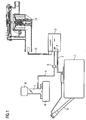
- FIG. 1 schematically shows an internal combustion engine 6 with air intake tract 7 and air filter 8.
- the internal combustion engine 6 is provided with a fuel tank 1 with filler neck 9.
- a line 3 leads to a fuel vapor storage 2, which may be, for example, a storage filled with activated charcoal.
- a vent valve 5 is arranged to the air intake tract 7 of the internal combustion engine 6 from.
- a vent line 10 is connected to the fuel vapor accumulator 2, which leads to a valve unit 11 which controls the ventilation of the fuel vapor accumulator 2 and thus of the fuel tank 1.
- the invention takes advantage of the presence of this valve unit 11 and integrates a purge pump into the valve unit to provide improved purging or regeneration of the fuel vapor accumulator, in particular when sufficient negative pressure is not provided by the air intake tract 7 of the internal combustion engine.
- FIG. 3 schematically shows a fuel system, which is essentially the FIG. 1 corresponds and in which in the valve unit in the ventilation line 10, a scavenge pump is integrated.
- This valve unit with integrated scavenge pump is provided with the reference numeral 20.
Landscapes
- Engineering & Computer Science (AREA)
- Chemical & Material Sciences (AREA)
- Combustion & Propulsion (AREA)
- Mechanical Engineering (AREA)
- General Engineering & Computer Science (AREA)
- Supplying Secondary Fuel Or The Like To Fuel, Air Or Fuel-Air Mixtures (AREA)
- Fuel Cell (AREA)
- Output Control And Ontrol Of Special Type Engine (AREA)
Claims (5)
- Moteur à combustion interne ayant un réservoir (1) à carburant, un accumulateur (2) de vapeurs de carburant pour accumuler des vapeurs de carburant, qui se dégagent du réservoir (1) à carburant, un conduit (4) de communication entre l'accumulateur (2) de vapeurs de carburant et un dispositif (7) d'aspiration d'air du moteur (6) à combustion interne pour conduire, pendant une phase de régénération, des vapeurs de carburant de l'accumulateur (2) de vapeurs de carburant au dispositif (7) d'aspiration d'air, une vanne (5) montée dans le conduit (4) de communication, un conduit (10) d'alimentation en air de l'accumulateur (2) de vapeurs de carburant et une unité (20) de vanne montée dans le conduit (10) d'alimentation en air pour commander l'alimentation en air de l'accumulateur (2) de vapeurs de carburant, une pompe d'air de balayage étant montée dans le conduit (10) d'alimentation en air de l'accumulateur (2) de vapeurs de carburant et alimentant en air de balayage l'accumulateur (2) de vapeurs de carburant pour le nettoyer, la pompe d'air de balayage étant intégrée dans l'unité (20) de vanne pour la commande de l'alimentation en air de l'accumulateur (2) de vapeurs de carburant ayant, avec cette unité, une enveloppe commune et étant montée en ayant son axe de roue dans le prolongement de l'obturateur (13), commandant l'arrivée d'air de balayage dans le conduit (10) d'alimentation, de l'unité (20) de vanne, caractérisé en ce que la pompe d'air de balayage est intégrée dans une unité (20) de vanne, qui sert, en outre, à commander la purge d'air de l'accumulateur (2) de vapeurs de carburant et en ce que l'unité (20) de vanne a, en outre, un élément (17) de commande, qui soulève l'obturateur (13) mécaniquement du siège (7) pour purger d'air le réservoir (1) à carburant.
- Moteur à combustion interne suivant la revendication 1, caractérisé en ce que la pompe d'air de balayage a, comme entraînement, un moteur (22) électrique.
- Moteur à combustion interne suivant l'une des revendications précédentes, caractérisé en ce que la pompe d'air de balayage est constituée sous la forme d'une pompe centrifuge à roue radiale.
- Moteur à combustion interne suivant la revendication 3, caractérisé en ce que la roue (21) de la pompe centrifuge à roue radiale a un diamètre, qui correspond à peu près au diamètre de l'élément (17) de commande de l'unité (20) de vanne.
- Moteur à combustion interne suivant l'une des revendications précédentes, caractérisé en ce que la pompe d'air de balayage est intégrée dans l'unité de vanne centrale d'un système NVLD de commande de l'alimentation en air et de la purge d'air d'un réservoir (1) à carburant.
Applications Claiming Priority (2)
| Application Number | Priority Date | Filing Date | Title |
|---|---|---|---|
| DE102010054668A DE102010054668A1 (de) | 2010-12-15 | 2010-12-15 | Brennkraftmaschine mit verbesserter Tankreinigung |
| PCT/EP2011/072464 WO2012080177A1 (fr) | 2010-12-15 | 2011-12-12 | Moteur à combustion interne comprenant un nettoyage de réservoir amélioré |
Publications (2)
| Publication Number | Publication Date |
|---|---|
| EP2652306A1 EP2652306A1 (fr) | 2013-10-23 |
| EP2652306B1 true EP2652306B1 (fr) | 2015-03-18 |
Family
ID=45349504
Family Applications (1)
| Application Number | Title | Priority Date | Filing Date |
|---|---|---|---|
| EP11796991.5A Active EP2652306B1 (fr) | 2010-12-15 | 2011-12-12 | Moteur a combustion interne avec nettoyage de reservoir de carburant améliorée |
Country Status (10)
| Country | Link |
|---|---|
| US (1) | US20130255645A1 (fr) |
| EP (1) | EP2652306B1 (fr) |
| JP (1) | JP2013545933A (fr) |
| KR (1) | KR20140040080A (fr) |
| CN (1) | CN103261650B (fr) |
| CA (1) | CA2820400C (fr) |
| DE (1) | DE102010054668A1 (fr) |
| ES (1) | ES2539358T3 (fr) |
| MX (1) | MX2013006800A (fr) |
| WO (1) | WO2012080177A1 (fr) |
Families Citing this family (22)
| Publication number | Priority date | Publication date | Assignee | Title |
|---|---|---|---|---|
| US9206772B2 (en) | 2011-07-11 | 2015-12-08 | Continental Automotive Systems, Inc. | Articulating poppet to seal a natural vacuum leak detection device |
| WO2014011161A1 (fr) * | 2012-07-11 | 2014-01-16 | Continental Automotive Systems, Inc. | Soupape champignon à articulation pour sceller un dispositif de détection de fuite de vide naturelle |
| DE102012018558B4 (de) | 2012-09-20 | 2022-11-10 | Audi Ag | Tankentlüftungssystem für ein Kraftfahrzeug |
| DE102012024297B4 (de) * | 2012-12-12 | 2016-02-11 | Audi Ag | Diagnosevorrichtung für ein Kraftstoffentlüftungssystem eines Kraftfahrzeuges |
| DE102013003957A1 (de) * | 2013-03-07 | 2014-09-11 | Volkswagen Aktiengesellschaft | Verfahren zum Betreiben eines Hybridfahrzeugs |
| DE102013209715A1 (de) * | 2013-05-24 | 2014-11-27 | Continental Automotive Gmbh | Verfahren zur Durchbruchsüberwachung eines Speicherelementes |
| DE102013209716A1 (de) * | 2013-05-24 | 2014-11-27 | Continental Automotive Gmbh | Kraftstofftanksystem |
| DE102013211073A1 (de) * | 2013-06-13 | 2014-12-18 | Bayerische Motoren Werke Aktiengesellschaft | Entlüftungssystem eines Kraftstofftanks |
| DE102013112586A1 (de) * | 2013-11-15 | 2015-05-21 | Dr. Ing. H.C. F. Porsche Aktiengesellschaft | Ventil für eine Tankbelüftung |
| US9587595B2 (en) * | 2013-12-11 | 2017-03-07 | Continental Automotive Systems, Inc. | Active purge pump system module for evaporative emission control system |
| DE102014224750B4 (de) | 2014-06-18 | 2017-03-02 | Magna Powertrain Bad Homburg GmbH | Vakuumsystem für eine Verbrennungskraftmaschine und Verfahren zum Betrieb desselben |
| DE102014216454A1 (de) * | 2014-08-19 | 2016-02-25 | Continental Automotive Gmbh | Ventileinheit mit Spülluftpumpe |
| DE102014216451A1 (de) * | 2014-08-19 | 2016-02-25 | Continental Automotive Gmbh | Kraftstofftanksystem |
| US9651002B2 (en) * | 2014-09-24 | 2017-05-16 | Ford Global Technologies, Llc | Systems and methods for reducing bleed emissions |
| DE102014222241B3 (de) * | 2014-10-30 | 2016-03-31 | Continental Automotive Gmbh | Elektrisch angetriebene Pumpe |
| JP6522373B2 (ja) * | 2015-03-06 | 2019-05-29 | 愛三工業株式会社 | 蒸発燃料処理装置 |
| US9752539B2 (en) * | 2015-06-18 | 2017-09-05 | GM Global Technology Operations LLC | Method for diagnosing leaks downstream of the purge flow control orifice |
| EP3238972B1 (fr) * | 2016-04-27 | 2019-12-18 | Magna Steyr Fuel Systems GesmbH | Raccord d'isolation |
| DE102017210768B4 (de) | 2017-06-27 | 2019-11-21 | Continental Automotive Gmbh | Verfahren und Steuerungsvorrichtung zum Betreiben eines Tankentlüftungssystems einer Brennkraftmaschine |
| FR3074232B1 (fr) * | 2017-11-27 | 2019-10-18 | Continental Automotive France | Procede de detection d'un defaut d'ecoulement de gaz dans une ligne de ventilation d'un dispositif de purge |
| DE102020210299B4 (de) | 2020-08-13 | 2022-12-08 | Vitesco Technologies GmbH | Verfahren und Steuerungsvorrichtung zum Betreiben eines Tankentlüftungssystems einer Brennkraftmaschine |
| CN116876122A (zh) * | 2023-07-31 | 2023-10-13 | 宜城市万众纱业有限责任公司 | 一种粗纱机轨道式清洁吸尘装置 |
Family Cites Families (19)
| Publication number | Priority date | Publication date | Assignee | Title |
|---|---|---|---|---|
| DE3935209C2 (de) * | 1989-10-23 | 2001-04-12 | Walter Holzer | Adsorbtionsfilter für Brennstoffdämpfe |
| US5495749A (en) * | 1993-05-14 | 1996-03-05 | Chrysler Corporation | Leak detection assembly |
| JP3614524B2 (ja) * | 1995-07-17 | 2005-01-26 | 株式会社日本自動車部品総合研究所 | 蒸発燃料処理装置 |
| US6283097B1 (en) * | 1997-08-25 | 2001-09-04 | John E. Cook | Automotive evaporative emission leak detection system |
| JP3516599B2 (ja) * | 1998-11-16 | 2004-04-05 | 株式会社日立ユニシアオートモティブ | 蒸発燃料処理装置のリーク診断装置 |
| JP3773406B2 (ja) * | 2000-10-04 | 2006-05-10 | 株式会社日本自動車部品総合研究所 | 蒸発燃料処理装置 |
| US6695895B2 (en) * | 2001-05-02 | 2004-02-24 | Toyota Jidosha Kabushiki Kaisha | Fuel vapor handling apparatus and diagnostic apparatus thereof |
| DE60312851T2 (de) * | 2003-08-28 | 2007-12-06 | Ford Global Technologies, LLC, Dearborn | Verfahren und Vorrichtung zur Leckdiagnose in einem Behälter |
| JP2006283702A (ja) * | 2005-04-01 | 2006-10-19 | Denso Corp | 電動エアポンプ装置、および蒸発燃料処理装置 |
| JP2006348754A (ja) * | 2005-06-13 | 2006-12-28 | Denso Corp | 蒸発燃料処理装置 |
| JP2007218161A (ja) * | 2006-02-16 | 2007-08-30 | Denso Corp | ベーン式ポンプ装置およびそれを用いたリークチェックシステム |
| US7481414B2 (en) * | 2006-05-05 | 2009-01-27 | Siemens Canada Limited | Natural vacuum leak detection device with magnetic damping |
| DE102007008119B4 (de) | 2007-02-19 | 2008-11-13 | Continental Automotive Gmbh | Verfahren zum Steuern einer Brennkraftmaschine und Brennkraftmaschine |
| DE102007013993B4 (de) | 2007-03-23 | 2011-12-22 | Continental Automotive Gmbh | Steuerverfahren für eine Brennkraftmaschine |
| DE102007033411A1 (de) * | 2007-07-18 | 2009-01-22 | Audi Ag | Fahrzeug, insbesondere Kraftfahrzeug mit Tankentlüftungssystem |
| JP4800271B2 (ja) * | 2007-07-27 | 2011-10-26 | 愛三工業株式会社 | 蒸発燃料排出抑制装置 |
| US20090084363A1 (en) * | 2007-09-27 | 2009-04-02 | Gm Global Technology Operations, Inc. | Regeneration of Evaporative Emision Control System for Plug-in Hybrid Vehicle |
| EP2055924B1 (fr) * | 2007-10-29 | 2011-08-10 | Magneti Marelli S.p.A. | Collecteur d'admission doté d'un circuit de récipient intégré pour moteur à combustion interne suralimenté |
| DE102008007030B4 (de) * | 2008-01-31 | 2019-07-11 | Continental Automotive Gmbh | Verfahren und Vorrichtung zur Überprüfung der Funktionsfähigkeit einer Tankentlüftungsvorrichtung für eine Brennkraftmaschine |
-
2010
- 2010-12-15 DE DE102010054668A patent/DE102010054668A1/de not_active Ceased
-
2011
- 2011-12-12 US US13/994,572 patent/US20130255645A1/en not_active Abandoned
- 2011-12-12 WO PCT/EP2011/072464 patent/WO2012080177A1/fr not_active Ceased
- 2011-12-12 ES ES11796991.5T patent/ES2539358T3/es active Active
- 2011-12-12 MX MX2013006800A patent/MX2013006800A/es active IP Right Grant
- 2011-12-12 KR KR1020137018195A patent/KR20140040080A/ko not_active Ceased
- 2011-12-12 CN CN201180060428.XA patent/CN103261650B/zh active Active
- 2011-12-12 JP JP2013543688A patent/JP2013545933A/ja active Pending
- 2011-12-12 CA CA2820400A patent/CA2820400C/fr not_active Expired - Fee Related
- 2011-12-12 EP EP11796991.5A patent/EP2652306B1/fr active Active
Also Published As
| Publication number | Publication date |
|---|---|
| DE102010054668A1 (de) | 2012-06-21 |
| EP2652306A1 (fr) | 2013-10-23 |
| CA2820400C (fr) | 2017-10-17 |
| CA2820400A1 (fr) | 2012-06-21 |
| CN103261650A (zh) | 2013-08-21 |
| US20130255645A1 (en) | 2013-10-03 |
| KR20140040080A (ko) | 2014-04-02 |
| WO2012080177A1 (fr) | 2012-06-21 |
| CN103261650B (zh) | 2015-09-16 |
| ES2539358T3 (es) | 2015-06-30 |
| MX2013006800A (es) | 2013-07-29 |
| JP2013545933A (ja) | 2013-12-26 |
Similar Documents
| Publication | Publication Date | Title |
|---|---|---|
| EP2652306B1 (fr) | Moteur a combustion interne avec nettoyage de reservoir de carburant améliorée | |
| EP2659121B1 (fr) | Dispositif de régénération sélective ou de réalisation d'un diagnostic de fuite d'un réservoir d'un système de ventilation de réservoir | |
| DE102012220147B4 (de) | Verfahren und system zur kraftstoffdampfsteuerung | |
| DE19645382A1 (de) | Tankanlage für ein Fahrzeug mit Verbrennungsmotor | |
| DE10358638A1 (de) | Gasdichtigkeits-Diagnose-Vorrichtung für einen Kraftstofftank mit einem Kraftstoffverdunstungs-Auslass-System | |
| DE102016210570A1 (de) | Tankentlüftungsmodul sowie Brennkraftmaschine mit derartigem Modul | |
| DE102010055319A1 (de) | Einrichtung zum Be- und Entlüften eines Kraftstofftanks | |
| DE102017207747A1 (de) | Ventilmodul | |
| DE19802078B4 (de) | Kraftfahrzeugtank | |
| DE102009036263A1 (de) | Verfahren zur Dichtheitsprüfung eines Tanksystems | |
| DE102013109459B4 (de) | Tankentlüftungsvorrichtung | |
| EP1377741B1 (fr) | Unite de detection de fuite de reservoir chauffante, notamment pour automobiles | |
| DE102008045010A1 (de) | Entlüftungseinrichtung für einen Kraftstoffbehälter eines Kraftfahrzeugs | |
| DE112017004375T5 (de) | Nockensystemisolationsmodul für verdunstungsemissionen | |
| DE102014222632B4 (de) | Aktives Spülpumpensystemmodul für ein Verdampfungs-Emissionssteuersystem | |
| DE19913440A1 (de) | Tankentlüftungssystem bei einem Kraftstofftank für Brennkraftmaschinen in Kraftfahrzeugen | |
| EP2411653A1 (fr) | Dispositif de dégazage de réservoir pour moteur à combustion interne suralimenté, et procédé de commande correspondant | |
| DE102007058232A1 (de) | Verfahren zur Regenerierung eines Adsorptionsfilters | |
| DE102010061429A1 (de) | Kraftfahrzeug | |
| WO2012155939A1 (fr) | Dispositif pour fixer des vapeurs provenant d'un réservoir de carburant | |
| DE102021200886A1 (de) | Kraftstoffgeruchskontrollsystem für fahrzeuge | |
| WO2013159890A1 (fr) | Procédé pour détecter une fuite dans un dispositif de dégazage de réservoir d'un véhicule à moteur et véhicule à moteur associé | |
| DE102004030911B4 (de) | Tankentlüftungssystem und zugehöriges Betriebsverfahren | |
| DE102014224750A1 (de) | Vakuumsystem und Verfahren zum Betrieb desselben | |
| WO2014044245A2 (fr) | Système de dégazage de réservoir pour un véhicule automobile |
Legal Events
| Date | Code | Title | Description |
|---|---|---|---|
| PUAI | Public reference made under article 153(3) epc to a published international application that has entered the european phase |
Free format text: ORIGINAL CODE: 0009012 |
|
| 17P | Request for examination filed |
Effective date: 20130715 |
|
| AK | Designated contracting states |
Kind code of ref document: A1 Designated state(s): AL AT BE BG CH CY CZ DE DK EE ES FI FR GB GR HR HU IE IS IT LI LT LU LV MC MK MT NL NO PL PT RO RS SE SI SK SM TR |
|
| DAX | Request for extension of the european patent (deleted) | ||
| GRAP | Despatch of communication of intention to grant a patent |
Free format text: ORIGINAL CODE: EPIDOSNIGR1 |
|
| INTG | Intention to grant announced |
Effective date: 20141009 |
|
| GRAS | Grant fee paid |
Free format text: ORIGINAL CODE: EPIDOSNIGR3 |
|
| GRAA | (expected) grant |
Free format text: ORIGINAL CODE: 0009210 |
|
| AK | Designated contracting states |
Kind code of ref document: B1 Designated state(s): AL AT BE BG CH CY CZ DE DK EE ES FI FR GB GR HR HU IE IS IT LI LT LU LV MC MK MT NL NO PL PT RO RS SE SI SK SM TR |
|
| REG | Reference to a national code |
Ref country code: GB Ref legal event code: FG4D Free format text: NOT ENGLISH |
|
| REG | Reference to a national code |
Ref country code: CH Ref legal event code: EP |
|
| REG | Reference to a national code |
Ref country code: IE Ref legal event code: FG4D Free format text: LANGUAGE OF EP DOCUMENT: GERMAN |
|
| REG | Reference to a national code |
Ref country code: AT Ref legal event code: REF Ref document number: 716753 Country of ref document: AT Kind code of ref document: T Effective date: 20150415 |
|
| REG | Reference to a national code |
Ref country code: DE Ref legal event code: R096 Ref document number: 502011006340 Country of ref document: DE Effective date: 20150430 |
|
| REG | Reference to a national code |
Ref country code: NL Ref legal event code: T3 |
|
| REG | Reference to a national code |
Ref country code: ES Ref legal event code: FG2A Ref document number: 2539358 Country of ref document: ES Kind code of ref document: T3 Effective date: 20150630 |
|
| PG25 | Lapsed in a contracting state [announced via postgrant information from national office to epo] |
Ref country code: NO Free format text: LAPSE BECAUSE OF FAILURE TO SUBMIT A TRANSLATION OF THE DESCRIPTION OR TO PAY THE FEE WITHIN THE PRESCRIBED TIME-LIMIT Effective date: 20150618 Ref country code: FI Free format text: LAPSE BECAUSE OF FAILURE TO SUBMIT A TRANSLATION OF THE DESCRIPTION OR TO PAY THE FEE WITHIN THE PRESCRIBED TIME-LIMIT Effective date: 20150318 Ref country code: HR Free format text: LAPSE BECAUSE OF FAILURE TO SUBMIT A TRANSLATION OF THE DESCRIPTION OR TO PAY THE FEE WITHIN THE PRESCRIBED TIME-LIMIT Effective date: 20150318 Ref country code: LT Free format text: LAPSE BECAUSE OF FAILURE TO SUBMIT A TRANSLATION OF THE DESCRIPTION OR TO PAY THE FEE WITHIN THE PRESCRIBED TIME-LIMIT Effective date: 20150318 Ref country code: SE Free format text: LAPSE BECAUSE OF FAILURE TO SUBMIT A TRANSLATION OF THE DESCRIPTION OR TO PAY THE FEE WITHIN THE PRESCRIBED TIME-LIMIT Effective date: 20150318 |
|
| REG | Reference to a national code |
Ref country code: LT Ref legal event code: MG4D |
|
| PG25 | Lapsed in a contracting state [announced via postgrant information from national office to epo] |
Ref country code: RS Free format text: LAPSE BECAUSE OF FAILURE TO SUBMIT A TRANSLATION OF THE DESCRIPTION OR TO PAY THE FEE WITHIN THE PRESCRIBED TIME-LIMIT Effective date: 20150318 Ref country code: GR Free format text: LAPSE BECAUSE OF FAILURE TO SUBMIT A TRANSLATION OF THE DESCRIPTION OR TO PAY THE FEE WITHIN THE PRESCRIBED TIME-LIMIT Effective date: 20150619 Ref country code: LV Free format text: LAPSE BECAUSE OF FAILURE TO SUBMIT A TRANSLATION OF THE DESCRIPTION OR TO PAY THE FEE WITHIN THE PRESCRIBED TIME-LIMIT Effective date: 20150318 |
|
| PG25 | Lapsed in a contracting state [announced via postgrant information from national office to epo] |
Ref country code: SK Free format text: LAPSE BECAUSE OF FAILURE TO SUBMIT A TRANSLATION OF THE DESCRIPTION OR TO PAY THE FEE WITHIN THE PRESCRIBED TIME-LIMIT Effective date: 20150318 Ref country code: EE Free format text: LAPSE BECAUSE OF FAILURE TO SUBMIT A TRANSLATION OF THE DESCRIPTION OR TO PAY THE FEE WITHIN THE PRESCRIBED TIME-LIMIT Effective date: 20150318 Ref country code: RO Free format text: LAPSE BECAUSE OF FAILURE TO SUBMIT A TRANSLATION OF THE DESCRIPTION OR TO PAY THE FEE WITHIN THE PRESCRIBED TIME-LIMIT Effective date: 20150318 Ref country code: PT Free format text: LAPSE BECAUSE OF FAILURE TO SUBMIT A TRANSLATION OF THE DESCRIPTION OR TO PAY THE FEE WITHIN THE PRESCRIBED TIME-LIMIT Effective date: 20150720 |
|
| PG25 | Lapsed in a contracting state [announced via postgrant information from national office to epo] |
Ref country code: IS Free format text: LAPSE BECAUSE OF FAILURE TO SUBMIT A TRANSLATION OF THE DESCRIPTION OR TO PAY THE FEE WITHIN THE PRESCRIBED TIME-LIMIT Effective date: 20150718 Ref country code: PL Free format text: LAPSE BECAUSE OF FAILURE TO SUBMIT A TRANSLATION OF THE DESCRIPTION OR TO PAY THE FEE WITHIN THE PRESCRIBED TIME-LIMIT Effective date: 20150318 |
|
| REG | Reference to a national code |
Ref country code: FR Ref legal event code: PLFP Year of fee payment: 5 Ref country code: DE Ref legal event code: R097 Ref document number: 502011006340 Country of ref document: DE |
|
| REG | Reference to a national code |
Ref country code: HU Ref legal event code: AG4A Ref document number: E024920 Country of ref document: HU |
|
| PLBE | No opposition filed within time limit |
Free format text: ORIGINAL CODE: 0009261 |
|
| STAA | Information on the status of an ep patent application or granted ep patent |
Free format text: STATUS: NO OPPOSITION FILED WITHIN TIME LIMIT |
|
| PG25 | Lapsed in a contracting state [announced via postgrant information from national office to epo] |
Ref country code: DK Free format text: LAPSE BECAUSE OF FAILURE TO SUBMIT A TRANSLATION OF THE DESCRIPTION OR TO PAY THE FEE WITHIN THE PRESCRIBED TIME-LIMIT Effective date: 20150318 |
|
| 26N | No opposition filed |
Effective date: 20151221 |
|
| PG25 | Lapsed in a contracting state [announced via postgrant information from national office to epo] |
Ref country code: SI Free format text: LAPSE BECAUSE OF FAILURE TO SUBMIT A TRANSLATION OF THE DESCRIPTION OR TO PAY THE FEE WITHIN THE PRESCRIBED TIME-LIMIT Effective date: 20150318 |
|
| PG25 | Lapsed in a contracting state [announced via postgrant information from national office to epo] |
Ref country code: MC Free format text: LAPSE BECAUSE OF FAILURE TO SUBMIT A TRANSLATION OF THE DESCRIPTION OR TO PAY THE FEE WITHIN THE PRESCRIBED TIME-LIMIT Effective date: 20150318 Ref country code: LU Free format text: LAPSE BECAUSE OF FAILURE TO SUBMIT A TRANSLATION OF THE DESCRIPTION OR TO PAY THE FEE WITHIN THE PRESCRIBED TIME-LIMIT Effective date: 20151212 |
|
| REG | Reference to a national code |
Ref country code: CH Ref legal event code: PL |
|
| REG | Reference to a national code |
Ref country code: IE Ref legal event code: MM4A |
|
| PG25 | Lapsed in a contracting state [announced via postgrant information from national office to epo] |
Ref country code: LI Free format text: LAPSE BECAUSE OF NON-PAYMENT OF DUE FEES Effective date: 20151231 Ref country code: IE Free format text: LAPSE BECAUSE OF NON-PAYMENT OF DUE FEES Effective date: 20151212 Ref country code: CH Free format text: LAPSE BECAUSE OF NON-PAYMENT OF DUE FEES Effective date: 20151231 |
|
| REG | Reference to a national code |
Ref country code: FR Ref legal event code: PLFP Year of fee payment: 6 |
|
| PG25 | Lapsed in a contracting state [announced via postgrant information from national office to epo] |
Ref country code: SM Free format text: LAPSE BECAUSE OF FAILURE TO SUBMIT A TRANSLATION OF THE DESCRIPTION OR TO PAY THE FEE WITHIN THE PRESCRIBED TIME-LIMIT Effective date: 20150318 Ref country code: BG Free format text: LAPSE BECAUSE OF FAILURE TO SUBMIT A TRANSLATION OF THE DESCRIPTION OR TO PAY THE FEE WITHIN THE PRESCRIBED TIME-LIMIT Effective date: 20150318 |
|
| PG25 | Lapsed in a contracting state [announced via postgrant information from national office to epo] |
Ref country code: CY Free format text: LAPSE BECAUSE OF FAILURE TO SUBMIT A TRANSLATION OF THE DESCRIPTION OR TO PAY THE FEE WITHIN THE PRESCRIBED TIME-LIMIT Effective date: 20150318 |
|
| PG25 | Lapsed in a contracting state [announced via postgrant information from national office to epo] |
Ref country code: MT Free format text: LAPSE BECAUSE OF FAILURE TO SUBMIT A TRANSLATION OF THE DESCRIPTION OR TO PAY THE FEE WITHIN THE PRESCRIBED TIME-LIMIT Effective date: 20150318 |
|
| REG | Reference to a national code |
Ref country code: FR Ref legal event code: PLFP Year of fee payment: 7 |
|
| PG25 | Lapsed in a contracting state [announced via postgrant information from national office to epo] |
Ref country code: TR Free format text: LAPSE BECAUSE OF FAILURE TO SUBMIT A TRANSLATION OF THE DESCRIPTION OR TO PAY THE FEE WITHIN THE PRESCRIBED TIME-LIMIT Effective date: 20150318 Ref country code: MK Free format text: LAPSE BECAUSE OF FAILURE TO SUBMIT A TRANSLATION OF THE DESCRIPTION OR TO PAY THE FEE WITHIN THE PRESCRIBED TIME-LIMIT Effective date: 20150318 |
|
| PG25 | Lapsed in a contracting state [announced via postgrant information from national office to epo] |
Ref country code: AL Free format text: LAPSE BECAUSE OF FAILURE TO SUBMIT A TRANSLATION OF THE DESCRIPTION OR TO PAY THE FEE WITHIN THE PRESCRIBED TIME-LIMIT Effective date: 20150318 |
|
| PGFP | Annual fee paid to national office [announced via postgrant information from national office to epo] |
Ref country code: CZ Payment date: 20181211 Year of fee payment: 8 Ref country code: AT Payment date: 20181220 Year of fee payment: 8 Ref country code: HU Payment date: 20181215 Year of fee payment: 8 Ref country code: NL Payment date: 20181219 Year of fee payment: 8 |
|
| PGFP | Annual fee paid to national office [announced via postgrant information from national office to epo] |
Ref country code: GB Payment date: 20181205 Year of fee payment: 9 |
|
| PGFP | Annual fee paid to national office [announced via postgrant information from national office to epo] |
Ref country code: ES Payment date: 20190124 Year of fee payment: 8 |
|
| PGFP | Annual fee paid to national office [announced via postgrant information from national office to epo] |
Ref country code: IT Payment date: 20191230 Year of fee payment: 9 |
|
| REG | Reference to a national code |
Ref country code: DE Ref legal event code: R081 Ref document number: 502011006340 Country of ref document: DE Owner name: VITESCO TECHNOLOGIES GMBH, DE Free format text: FORMER OWNER: CONTINENTAL AUTOMOTIVE GMBH, 30165 HANNOVER, DE |
|
| PG25 | Lapsed in a contracting state [announced via postgrant information from national office to epo] |
Ref country code: CZ Free format text: LAPSE BECAUSE OF NON-PAYMENT OF DUE FEES Effective date: 20191212 |
|
| REG | Reference to a national code |
Ref country code: NL Ref legal event code: MM Effective date: 20200101 |
|
| REG | Reference to a national code |
Ref country code: AT Ref legal event code: MM01 Ref document number: 716753 Country of ref document: AT Kind code of ref document: T Effective date: 20191212 |
|
| REG | Reference to a national code |
Ref country code: BE Ref legal event code: MM Effective date: 20191231 |
|
| GBPC | Gb: european patent ceased through non-payment of renewal fee |
Effective date: 20191212 |
|
| PG25 | Lapsed in a contracting state [announced via postgrant information from national office to epo] |
Ref country code: NL Free format text: LAPSE BECAUSE OF NON-PAYMENT OF DUE FEES Effective date: 20200101 |
|
| PG25 | Lapsed in a contracting state [announced via postgrant information from national office to epo] |
Ref country code: GB Free format text: LAPSE BECAUSE OF NON-PAYMENT OF DUE FEES Effective date: 20191212 |
|
| PG25 | Lapsed in a contracting state [announced via postgrant information from national office to epo] |
Ref country code: HU Free format text: LAPSE BECAUSE OF NON-PAYMENT OF DUE FEES Effective date: 20191213 Ref country code: BE Free format text: LAPSE BECAUSE OF NON-PAYMENT OF DUE FEES Effective date: 20191231 Ref country code: AT Free format text: LAPSE BECAUSE OF NON-PAYMENT OF DUE FEES Effective date: 20191212 |
|
| REG | Reference to a national code |
Ref country code: ES Ref legal event code: FD2A Effective date: 20210601 |
|
| REG | Reference to a national code |
Ref country code: DE Ref legal event code: R084 Ref document number: 502011006340 Country of ref document: DE |
|
| PG25 | Lapsed in a contracting state [announced via postgrant information from national office to epo] |
Ref country code: ES Free format text: LAPSE BECAUSE OF NON-PAYMENT OF DUE FEES Effective date: 20191213 |
|
| PG25 | Lapsed in a contracting state [announced via postgrant information from national office to epo] |
Ref country code: IT Free format text: LAPSE BECAUSE OF NON-PAYMENT OF DUE FEES Effective date: 20201212 |
|
| REG | Reference to a national code |
Ref country code: DE Ref legal event code: R081 Ref document number: 502011006340 Country of ref document: DE Owner name: SCHAEFFLER TECHNOLOGIES AG & CO. KG, DE Free format text: FORMER OWNER: VITESCO TECHNOLOGIES GMBH, 30165 HANNOVER, DE Ref country code: DE Ref legal event code: R081 Ref document number: 502011006340 Country of ref document: DE Owner name: VITESCO TECHNOLOGIES GMBH, DE Free format text: FORMER OWNER: VITESCO TECHNOLOGIES GMBH, 30165 HANNOVER, DE |
|
| P01 | Opt-out of the competence of the unified patent court (upc) registered |
Effective date: 20230530 |
|
| REG | Reference to a national code |
Ref country code: DE Ref legal event code: R081 Ref document number: 502011006340 Country of ref document: DE Owner name: SCHAEFFLER TECHNOLOGIES AG & CO. KG, DE Free format text: FORMER OWNER: VITESCO TECHNOLOGIES GMBH, 93055 REGENSBURG, DE |
|
| PGFP | Annual fee paid to national office [announced via postgrant information from national office to epo] |
Ref country code: FR Payment date: 20251223 Year of fee payment: 15 |
|
| PGFP | Annual fee paid to national office [announced via postgrant information from national office to epo] |
Ref country code: DE Payment date: 20251231 Year of fee payment: 15 |