EP2653230A2 - Crushing roll with edge protection - Google Patents
Crushing roll with edge protection Download PDFInfo
- Publication number
- EP2653230A2 EP2653230A2 EP13163534.4A EP13163534A EP2653230A2 EP 2653230 A2 EP2653230 A2 EP 2653230A2 EP 13163534 A EP13163534 A EP 13163534A EP 2653230 A2 EP2653230 A2 EP 2653230A2
- Authority
- EP
- European Patent Office
- Prior art keywords
- roll
- flange
- ring
- grinding
- edge ring
- Prior art date
- Legal status (The legal status is an assumption and is not a legal conclusion. Google has not performed a legal analysis and makes no representation as to the accuracy of the status listed.)
- Granted
Links
Images





Classifications
-
- B—PERFORMING OPERATIONS; TRANSPORTING
- B02—CRUSHING, PULVERISING, OR DISINTEGRATING; PREPARATORY TREATMENT OF GRAIN FOR MILLING
- B02C—CRUSHING, PULVERISING, OR DISINTEGRATING IN GENERAL; MILLING GRAIN
- B02C4/00—Crushing or disintegrating by roller mills
- B02C4/28—Details
- B02C4/30—Shape or construction of rollers
- B02C4/305—Wear resistant rollers
Definitions
- the edge ring 52 includes a wear coating 112.
- the wear coating 112 can be either applied to the edge ring 52 after formation of the edge ring 42 or during the initial forming process.
- the wear coating 112 provides enhanced durability for the outer face surface 74. Since the outer face surface 74 is subject to additional wear, the use of the wear coating 112 will enhance the life and durability of the edge ring 52. It is contemplated that the wear coating 112 could be a separate component that is positioned on the edge ring 52 during the assembly process. However, it is contemplated that the wear coating 112 will be preferably permanently attached to the edge ring 52. If the edge ring 52 is constructed from a hard, durable material, the wear coating 112 could be eliminated.
Landscapes
- Engineering & Computer Science (AREA)
- Food Science & Technology (AREA)
- Crushing And Grinding (AREA)
- Rolls And Other Rotary Bodies (AREA)
Abstract
Description
- The present disclosure generally relates to a grinding assembly including a pair of grinding rolls for the pressure comminution of materials. More specifically, the present disclosure relates to a grinding assembly including a grinding roll and a flange roll that each include a wear assembly that enhances the durability of the roll at the side edge of each of the grinding rolls.
- Presently, rolling mills grind material by drawing the material into a roller nip formed by two counter-rotating grinding rolls that are separated from each other and subject to a pressurized force. The material being ground passes between the nip formed between the pair of grinding rolls. The surfaces of each of the grinding rolls are thus subject to a high level of wear.
- It is known to make the outer surface of each of the grinding rolls more wear resistant by including a series of prefabricated hard metal bodies, such as studs, that extend from the cylindrical outer surface of the grinding roll. The stud bolts typically protrude from the outer surface of the roll body such that during the crushing action, a bed of material forms along the outer surface of the roll body between the studs to provide additional wear resistance for the roll body.
- In addition to the outer surface of the grinding roll, the end faces and the transitional edge between the outer surface and the end faces of the roll bodies are also subjected to a high level of wear during the continued pressure comminution of material. It is known to provide different types of reinforced edges on the roller body to reduce the amount of wear seen by the grinding roll. As an example,
U.S. Patent Nos. 7,497,396 and7,510,135 disclose different types of edge protectors that increase the durability of the edge of a grinding roll. Although these two references disclose different types of edge protection, limitations exist in each of the systems disclosed therein. - The present disclosure relates to a grinding assembly for the comminution of material. The grinding assembly includes a grinding roll and a flange roll that are positioned adjacent to each other to define an infeed nip that receives material for comminution. The grinding roll and the flange roll are biased into engagement with each other.
- The grinding roll and the flange roll both include a roll body that has a cylindrical outer surface that extends axially between a pair of opposite ends. The cylindrical outer surface of the roll body is configured to receive a series of studs that enhance the wear and durability of the cylindrical outer surface.
- The roll body includes a side groove that is formed at each end of the roll body. The side groove includes a support shoulder that extends axially inward from a side face of the roll body. The support shoulder is recessed from the outer surface of the roll body.
- An edge ring is received within each side groove and forms part of a wear assembly. The edge ring includes a series of receiving cavities that are spaced along the outer circumference of the edge ring. In one embodiment of the disclosure, the edge ring is formed from a plurality of individual edge ring sections that are joined in an end-to-end or interlocking configuration. Alternatively, the edge ring could be formed from a single, unitary component. The edge ring includes a series of connector openings that each receive a connector to attach the edge ring to the roll body. Preferably, the connectors are removable and replaceable to attach the edge ring to the roll body.
- The plurality of wear members received by the edge ring are each configured to create a wear resistant edge defined as the transition between the side face and cylindrical outer surface of the roll body. Each wear member includes an attachment portion that is received within one of the plurality of spaced receiving cavities formed on the edge ring. Preferably, the wear members are securely received within the receiving cavities and are positioned in an end-to-end or interlocking configuration to define each edge of the roll body.
- The grinding assembly further includes a flange roll that includes the same components as the grinding roll. However, the flange roll further includes a flange ring that is positioned axially adjacent to the end ring. The flange ring extends axially outward from the end ring and includes an outer surface that is spaced radially from the outer surface of the roll body. In a contemplated embodiment, the flange ring is formed from a plurality of flange ring sections that are positioned adjacent to each other in an end to end or interlocking configuration. The flange ring sections are each secured to the roll body by a common series of connectors that also extend through the edge ring such that the common connectors secure both the edge ring and the flange ring to the roll body.
- When the grinding roll and the flange roll are positioned adjacent to each other, the flange ring formed on the flange roll is positioned axially outward from the edge ring of the grinding roll. The interaction between the grinding roll and the flange roll creates the infeed nip while the flange aids in maintaining a high pressure crushing chamber on the side of the roll including the flange. In one contemplated embodiment, one or more shims are positioned between the edge ring and the flange ring during the construction of the flange roll. The shims provide the required spacing between the flange ring and the edge ring such that common components can be utilized to form both the grinding roll and the flange roll. Alternatively, each of the flange sections could include a ledge to create the required spacing.
- Various other features, objects and advantages of the invention will be made apparent from the following description taken together with the drawings.
- The drawings illustrate the best mode presently contemplated of carrying out the disclosure. In the drawings:
-
Fig. 1 is an isometric view of a grinding assembly including a grinding roll and a flange roll constructed in accordance with the present disclosure; -
Fig. 2 is an isometric view of the flange roll; -
Fig. 3 is an exploded isometric view of the flange roll; -
Fig. 4 is a section view taken along line 4-4 ofFig. 2 ; -
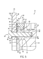
Fig. 5 is a magnified view taken alone line 5-5 ofFig. 4 ; -
Fig. 6 is an isometric view of the grinding roll shown inFig. 1 ; -
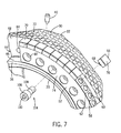
Fig. 7 is a magnified, partial exploded view of the grinding roll; -
Fig. 8 is a section view taken along line 8-8 ofFig. 6 ; and -
Fig. 9 is a magnified, section view taken along line 9-9 ofFig. 8 . -
Fig. 1 illustrates agrinding assembly 10 for the pressure comminution of material. Thegrinding assembly 10 shown inFig. 1 includes a pair of grinding rolls, referred to asgrinding roll 12 andflange roll 14 that are positioned adjacent to each other to define aninfeed nip 16. During operation, thegrinding roll 12 andflange roll 14 rotate toward each other (see arrows) such that material is drawn into theinfeed nip 16. Thegrinding roll 12 and theflange roll 14 are each respectively rotatable about asupport shaft 18. A mechanical source of pressure (not shown) bias thegrinding roll 12 and the flange roll 14 toward each other such that the source of pressure crushes the material passing through theinfeed nip 16. - Both the
grinding roll 12 and theflange roll 14 include a generallycylindrical roll body 20 that is defined by a cylindricalouter surface 22. The cylindrical roll body extends along and is rotatable about a longitudinal axis that passes through the center of thesupport shaft 18. In accordance with the present disclosure, both thegrinding roll 12 and theflange roll 14 include many common components and are similar in many respects. In the following description, common components are referred to by common reference numerals to facilitate ease of understanding. Theflange roll 14 is generally illustrated inFigs. 2-5 while thegrinding roll 12 is illustrated inFigs. 6-9 . In the description that follows for each of the rolls, reference may be made to the drawing Figures of the other type of roll. Since the grindingroll 12 andflange roll 14 share many components, the use of drawings showing one roll to describe the other roll is possible. - As illustrated in
Fig. 1 , theflange roll 14 includes a pair of flange rings 24 that are positioned axially outward of thecylindrical roll body 22 of the grindingroll 12 when the grindingroll 12 and theflange roll 14 are positioned to create the infeed nip 16. Although aflange roll 14 is shown in the embodiment of the grindingassembly 10 ofFig. 1 , it should be understood that theflange roll 14 could be replaced by another grindingroll 12 in configurations in which the flange rings 24 are not required. As described, theflange roll 14 and the grindingroll 12 include many common components and the details of the construction for both the grindingroll 12 and theflange roll 14 will be described in much greater detail below. -
Figs. 2-5 illustrate the construction of theflange roll 14. As indicated above, theflange roll 14 includes a pair of flange rings 24 positioned on opposite axial ends of theflange roll 14. As illustrated inFig. 2 , theflange ring 24 defines a circularouter edge surface 26 that is spaced radially from theouter surface 22 of theroll body 20. In the embodiment shown inFig. 2 , theflange ring 24 is formed from six separateflange ring sections 28 that are positioned adjacent to each other in an end-to-end configuration to define theflange ring 24. Alternatively, theflange ring sections 28 could interlock with each other. Although six separateflange ring sections 28 are shown in the embodiment ofFig. 2 , it should be understood that theflange ring 24 could be composed of fewer or greater numbers offlange ring sections 28 while operating within the scope of the present disclosure. Additionally, theflange ring 24 could be created as a single, unitary structure. The use of multipleflange ring sections 28 aids in both the construction of theflange roll 14 and the manufacturability of theflange ring sections 28. - Referring now to
Figs. 3 and4 , theflange roll 14 includes thecylindrical roll body 20 defined by aninner surface 30 and theouter surface 22. Preferably, theroll body 20 is formed from a durable, metallic material. Theinner surface 30 receives and engages the support shaft that imparts rotation to theflange roll 14. - The
roll body 20 extends axially from afirst end 32 to asecond end 34. The first and second ends 32, 34 of theflange roll 14 are defined by opposite side faces 36. Since theroll body 20 is annular, both of the side faces 36 are also annular. - As best illustrated in
Figs. 4 and5 , theroll body 20 includes a series of receiving bores 38 that extend radially into theroll body 20 from theouter surface 22. Each of the receiving bores 38 receives astud 40, as can best be seen inFig. 7 . Each of thestuds 40 is formed from material that is more durable than the roll body. Thestuds 40 can be replaced when worn to extend the life of the grinding roll and flange roll. As illustrated inFig. 4 , thetop end 42 of thestud 40 extends past theouter surface 22 such that material contacting theflange roll 14 is first engaged by thetop end 42 of thestud 40. The crushed material forms a bed of material between thestuds 40 to also enhance the durability of theouter surface 22. - Referring now to
Fig. 5 , each end of theflange roll 14 includes aside groove 44 formed at the junction between the cylindricalouter surface 22 and theside face 36. Theside groove 44 defines asupport shoulder 46 that extends generally along the longitudinal axis of theflange roll 14. Theside groove 44 is further defined by aninner wall 48 that is spaced axially inward from theside face 36. Theinner wall 48 extends generally radially relative to the longitudinal axis of theflange roll 14. - As illustrated in
Fig. 5 , theside groove 44 is formed to receive and support awear assembly 50. Thewear assembly 50 is received and positioned within theside groove 44 to increase the durability of the side edges of theflange roll 14. Thewear assembly 50 includes anannular edge ring 52 that extends around the entire edge of theroll body 20 between theouter surface 22 and theside face 36. Theedge ring 52 is shown in the embodiment ofFig. 3 as formed from a series ofedge ring sections 54 that are positioned adjacent to each other to extend around the entire side edge of theflange roll 14. Although the embodiment illustrated in the drawing Figures includes three separateedge ring sections 54, it should be understood that the number ofedge ring sections 54 could be increased or decreased while operating within the scope of the present disclosure. The use of multipleedge ring sections 54 facilitates both the manufacture of theedge ring sections 54 as well as the installation of theend ring sections 54 onto the roll body of theflange roll 14. - Referring now to
Figs. 3 and5 , each of theedge ring sections 54 includes aninner surface 56 and anouter surface 58. Theinner surface 56 rests upon and is supported by thesupport shoulder 46 of theside groove 44. - As can be understood in
Figs. 5 and7 , theedge ring 52 includes a series of spaced receivingcavities 60 that extend into the body of theedge ring 52 from theouter surface 58. As illustrated inFig. 7 , theouter surface 58 of theedge ring 52 includes a series offlat seats 62 onto which the receivingcavities 60 open. Theflat seats 62 provide a flat mounting surface for one of a plurality ofwear members 64. Althoughflat seats 62 are illustrated, theseats 62 could be curved and configured to match a corresponding curved surface on the underside of thebody portion 66 of eachwear member 64. - As illustrated in
Fig. 5 , each of thewear members 64 includes abody portion 66 and a dependingattachment portion 68. The dependingattachment portion 68 extends into the receivingcavity 60 and is retained therein. The length of theattachment portion 68 should be less than the depth of the receivingcavity 60 such that thewear members 64 rest on theouter surface 58 and resist the crushing force between the rolls. In one embodiment of the disclosure, an adhesive is positioned between theattachment portion 68 and the receivingcavity 60 to secure thewear member 64 to theedge ring 52. In the embodiment shown inFig. 5 , thewear member 64 includes a generally planarouter surface 70 that is generally flush with theouter surface 22 of theroll body 20. As can be seen in the view ofFig. 9 , thewear member 64 also includes anaxial end face 72. In the embodiment shown inFig. 9 , theaxial end face 72 is spaced axially inward from theside face 36 of theroll body 20. In the embodiment illustrated, the spacing between theend face 72 and theside face 36 is approximately 2 mm, although other dimensions are contemplated as being within the scope of the present disclosure. - Referring back to
Fig. 5 , when theedge ring 52 is received within theside groove 44, theouter face surface 74 of theedge ring 52 and theend face 72 of thewear member 64 are both spaced axially inward from theside face 36 of theroll body 20. Thus, before theflange ring 24 is mounted to theedge ring 52, afirst shim 76 is positioned adjacent and in contact with theouter face surface 74 of theedge ring 52. As illustrated inFig. 3 , thefirst shim 76 includes a series of cut outsections 78 along the radiallyinward edge 80. When thefirst shim 76 is positioned adjacent theouter face surface 74 of eachedge ring section 54, the cut outsections 78 are generally aligned with one of a series ofconnector openings 82. Theconnector openings 82 are generally in alignment with a corresponding number ofbores 84 formed in theinner wall 48 of the roll body which defines a portion of theside groove 44. - Referring back to
Fig. 5 , asecond shim 86 is positioned between theflange ring 24 and both theend face 72 of thewear member 64 and thefirst shim 76. Thesecond shim 86 creates a generally uniform mounting surface that receives aninner surface 88 of theflange ring 24. The use of the pair ofremovable shims roll body 20 to be configured as either the grinding roll 12 (Fig. 1 ) or the flange roll 14 (Fig. 1 ). - Although the embodiment shown in the figures includes a pair of shims positioned between the
flange ring 24 and theroll body 20, it is contemplated that theflange ring 24 could be constructed with a ledge on theinner surface 88 to provide the required support. In either case, the shims or an integral ledge will provide the required structural support for theflange ring 24 on theroll body 20. - As can be seen in
Fig. 3 , theflange ring sections 28 that define theflange ring 24 each include a series ofconnector openings 90 formed near theinner edge 92. As described previously, each of theflange ring sections 28 extends from theinner edge 92 to anouter edge 26. Theconnector openings 90 are spaced in conformance with the spacing of theconnector openings 82 formed in theedge ring sections 54 and thebores 84 formed in the roll body. In this manner, a common series ofconnectors 94 can be used to secure both theflange ring 24 and theedge ring 52 in theside groove 44 formed in the roll body. - Referring back to
Fig. 5 , in the embodiment illustrated, theconnectors 94 each include ahead portion 96 and a threadedshaft 98. The threadedshaft 98 is received and retained by a corresponding series of internal threads in one of thebores 84 that extends into theroll body 20 from theinner wall 48 of theside groove 44. Although threaded bolts are shown in the embodiment of the invention, it should be understood that other types of connectors could be utilized while operating within the scope of the present disclosure. In the embodiment shown inFig. 5 , awasher 100 is positioned between thehead portion 96 and theouter surface 102 of theflange ring 24. - Referring back to
Fig. 2 , thehead portion 96 of each of the series of connectors protrudes past theouter surface 102 of theflange ring 24 as illustrated. Each of theconnectors 94 can be removed individually to either remove theflange ring 24 or install a flange ring on the roll body. In another contemplated embodiment, theconnector openings 90 formed in eachflange ring section 28 could be replaced by a slot that is open to theinner edge 92. The use of an open slot rather than a circular connector opening would only require theconnectors 94 to be loosened and not entirely removed prior to removal of theflange ring section 28. This configuration would be particularly desirable in limited space applications since theconnectors 94 would not need to be completely removed to replace theflange ring section 28. - In a similar manner, the
connector openings 82 formed in theedge ring sections 54 could be replaced with open slots, which would allow the edge ring sections to be removed without completely removing theconnectors 94. Further, theedge ring sections 54 and theflange ring sections 28 could be configured such that every other connector would support both sections while the alternate connectors would only support the edge ring section. In such a configuration, theflange ring sections 28 could be removed and theedge ring sections 54 would remain securely supported on theroll body 20. - The
flange roll 14 shown in the drawing figures includes aflange ring 24 on each end of theroll body 20. However, it is contemplated that aflange roll 14 could be configured to include only oneflange ring 24 on one end of theroll body 20. Additionally, it is contemplated that two flange rolls 14 could be used where eachflange roll 14 would include a flange ring on opposite ends. In such an embodiment, each of the rolls inFig. 1 would include aflange ring 24. - The
flange roll 14 described inFigs. 2-5 includes many of the same components as utilized to form the grindingroll 12 shown inFigs. 6-9 . Specifically, the grindingroll 12 shown inFig. 6 can be reconfigured to theflange roll 14 by adding thefirst shim 76 and thesecond shim 86 between theflange ring 24, as is illustrated inFig. 3 . If theflange ring 24 and the first andsecond shims roll 12 shown inFig. 6 . - As illustrated in
Fig. 6 , theconnectors 104 used to secure theedge ring sections 54 to the roll body each include ahead portion 106 that is either flush with or slightly recessed from theouter face surface 74 of theedge ring sections 54. Each of theconnectors 104 is received within theconnector openings 82 of theedge ring section 54 in a similar manner to the receipt of the connectors shown in the flange roll design discussed previously. - As illustrated in
Figs. 6 and7 , the series ofwear members 64 are positioned in an end-to-end configuration to define both of the pair of spaced side edges of the grindingroll 12. Alternatively, the wear members could interlock with each other to form the side edges of the grindingroll 12. Theouter surfaces 70 of each of thewear members 64 provides enhanced wear durability for the outer surface of the grinding roll near each edge. Likewise, the end faces 72 of each of thewear members 64 are positioned adjacent to each other to enhance the durability of the grinding roll at the transition between theouter surface 22 and theside face 36. As previously described, each of thewear members 64 include anattachment section 68 that is received and retained within one of the receivingcavities 60 formed in theedge ring 52. Although thewear members 64 are each shown being received and retained in one of the receivingcavities 60, thewear members 64 could be configured to include multiple dependingsections 64 that would be received in adjacent receivingcavities 60 spaced along theedge ring 52. - The
edge ring 52, in turn, is received and retained within theside groove 44 formed at the transition between theouter surface 22 and theside face 36 of theroll body 20. Theside groove 44 is defined by thesupport shoulder 46 and theinner wall 48. Theinner wall 48 includes the series ofbores 84 that each receive the threadedshaft 108 of theconnector 104. Since theconnector 104 is generally recessed from theouter face surface 74, thehead portion 106 includes a recessedengagement area 110 that receives the correct type of tool to rotate theconnector 104. -
Figs. 8 and9 further illustrate the position of theedge ring 52 within theside groove 44 of the grindingroll 12. The series ofconnectors 104 are used to secure theedge ring 52 to theroll body 20 in a similar manner as described with respect to the flange roll. Like the flange roll, the grindingroll 12 includes a series ofstuds 40 each received in one of a series of receiving bores 38 extending radially inward from theouter surface 22. Each of the edge rings positioned on opposite ends of the grindingroll 12 include and receive thewear members 64. - Referring now to
Fig. 9 , in the embodiment illustrated, theedge ring 52 includes awear coating 112. Thewear coating 112 can be either applied to theedge ring 52 after formation of theedge ring 42 or during the initial forming process. Thewear coating 112 provides enhanced durability for theouter face surface 74. Since theouter face surface 74 is subject to additional wear, the use of thewear coating 112 will enhance the life and durability of theedge ring 52. It is contemplated that thewear coating 112 could be a separate component that is positioned on theedge ring 52 during the assembly process. However, it is contemplated that thewear coating 112 will be preferably permanently attached to theedge ring 52. If theedge ring 52 is constructed from a hard, durable material, thewear coating 112 could be eliminated.
Claims (15)
- A grinding roll comprising:a roll body having a cylindrical outer surface extending axially between a pair of opposite ends;a side groove formed at each end of the roll body, the side groove including a support shoulder recessed from the outer surface of the roll body;an edge ring received within each side groove, the edge ring including a plurality of spaced receiving cavities; anda plurality of wear members each received and retained in at least one of the receiving cavities of the edge ring, wherein the wear members are positioned along the edge ring to define an edge of the grinding roll.
- The grinding roll of claim 1 wherein the edge ring is attached to the roll body by a series of removable connectors that extend axially into the roll body.
- The grinding roll of claim 1 or 2 wherein the edge ring is formed from a plurality of f edge ring sections positioned adjacent to each other along the side groove.
- The grinding roll of any one of the preceding claims wherein the plurality of receiving cavities are open radially relative to the roll body.
- The grinding roll of claim 4 wherein the wear members each include a body portion and a depending attachment portion, wherein the attachment portion is secured within one of the receiving cavities.
- The grinding roll of any one of the preceding claims further comprising a flange ring attached to the end ring, the flange ring having an outer edge that extends radially past the outer surface of the roll body.
- The grinding roll of claim 6 wherein the flange ring is formed from a plurality of flange ring sections positioned adjacent to each other.
- The grinding roll of claim 6 or 7 wherein the flange ring and the edge ring are attached to the roll body by a common series of connectors.
- The grinding roll of claim 8 wherein each of the connectors pass through both the flange ring and the edge ring.
- The grinding roll of claim 9 further comprising an annular shim positioned between the edge ring and the flange ring to provide spacing between the flange ring and the edge ring.
- The grinding roll of any one of the preceding claims wherein the edge ring includes a hardened outer surface.
- A grinding assembly for the comminution of material comprising:a grinding roll as claimed in any one of the preceding claims, and a flange roll, the grinding roll and the flange roll being positioned adjacent to each other to define an infeed nip therebetween, wherein the flange roll comprises:a roll body having a cylindrical outer surface extending axially between a pair of opposite ends;a side groove formed at each end of the roll body, the side groove including a support shoulder recessed from the outer surface of the roll body;an edge ring received within each side groove, the edge ring including a plurality of spaced receiving cavities; anda plurality of wear members each received and retained in at least one of the receiving cavities of the edge ring, wherein the wear members are positioned along the edge ring to define an edge of the grinding roll;wherein the flange roll further comprises a flange ring attached to the end ring, the flange ring having an outer edge that extends radially past the outer surface of the roll body,wherein the flange ring is located axially outward from the edge ring of the grinding roll.
- The grinding roll of claim 12 wherein the edge ring is formed from a plurality of edge ring sections positioned adjacent to each other along the side groove.
- The grinding assembly of claim 12 or 13 wherein the flange ring is formed from a plurality of flange ring sections positioned adjacent to each other.
- The grinding assembly of any one of claims 12-14 wherein the flange ring and the edge ring are attached to the roll body by a series of common connectors.
Applications Claiming Priority (1)
| Application Number | Priority Date | Filing Date | Title |
|---|---|---|---|
| US13/451,875 US8833687B2 (en) | 2012-04-20 | 2012-04-20 | Crushing roll with edge protection |
Publications (3)
| Publication Number | Publication Date |
|---|---|
| EP2653230A2 true EP2653230A2 (en) | 2013-10-23 |
| EP2653230A3 EP2653230A3 (en) | 2016-07-27 |
| EP2653230B1 EP2653230B1 (en) | 2017-09-27 |
Family
ID=48142639
Family Applications (1)
| Application Number | Title | Priority Date | Filing Date |
|---|---|---|---|
| EP13163534.4A Active EP2653230B1 (en) | 2012-04-20 | 2013-04-12 | Crushing roll with edge protection |
Country Status (15)
| Country | Link |
|---|---|
| US (1) | US8833687B2 (en) |
| EP (1) | EP2653230B1 (en) |
| CN (2) | CN104254400B (en) |
| AR (1) | AR090729A1 (en) |
| AU (1) | AU2013202272B2 (en) |
| BR (1) | BR112014026179B8 (en) |
| CA (1) | CA2870824C (en) |
| CL (1) | CL2014002799A1 (en) |
| DK (1) | DK2653230T3 (en) |
| MX (1) | MX339507B (en) |
| PE (1) | PE20142369A1 (en) |
| RU (1) | RU2624290C2 (en) |
| UA (1) | UA114318C2 (en) |
| WO (1) | WO2013158346A1 (en) |
| ZA (1) | ZA201407212B (en) |
Cited By (8)
| Publication number | Priority date | Publication date | Assignee | Title |
|---|---|---|---|---|
| EP3088085A1 (en) * | 2015-04-29 | 2016-11-02 | Takraf GmbH | Side sealing protection for the roller in a roller press |
| WO2018007309A1 (en) * | 2016-07-05 | 2018-01-11 | Thyssenkrupp Industrial Solutions Ag | Grinding roller having an edge protection device |
| DE102018108690A1 (en) | 2018-04-12 | 2019-10-17 | Thyssenkrupp Ag | Grinding roller and roller press |
| WO2020260308A1 (en) * | 2019-06-28 | 2020-12-30 | Thyssenkrupp Industrial Solutions Ag | Roller mill having rim elements and method for setting an end-face gap of the roller mill |
| WO2024089672A1 (en) * | 2022-10-28 | 2024-05-02 | Flsmidth A/S | Corner block segment for a roll of a comminution device |
| BE1031004B1 (en) * | 2022-10-28 | 2024-06-04 | Smidth As F L | Corner block segment for a roller of a shredding device |
| US12012371B2 (en) | 2019-09-05 | 2024-06-18 | Thyssenkrupp Uhde Gmbh | Process of preparing alcohols |
| GB2642324A (en) * | 2024-07-02 | 2026-01-07 | Weir Minerals Netherlands Bv | Roller for grinding machine |
Families Citing this family (18)
| Publication number | Priority date | Publication date | Assignee | Title |
|---|---|---|---|---|
| WO2015123770A1 (en) * | 2014-02-19 | 2015-08-27 | Cast Steel Products Lp, By Its General Partner Cast Steel Products Gp Ltd. | Segmented roller and method of reconditioning same |
| WO2015123772A1 (en) * | 2014-02-19 | 2015-08-27 | Cast Steel Products Lp, By Its General Partner Cast Steel Products Gp Ltd. | Roller with replaceable edge reinforcements |
| CN104307592B (en) * | 2014-10-29 | 2017-08-04 | 成都利君实业股份有限公司 | A kind of roll squeezer and high-pressure roller mill roller side antiwear device |
| CN105728106A (en) * | 2016-05-09 | 2016-07-06 | 张进才 | Roller and roller device |
| US20180318841A1 (en) * | 2017-05-02 | 2018-11-08 | Flsmidth A/S | Roller press with boltless edge wear components and a method for securing the same |
| DE102017208014A1 (en) | 2017-05-11 | 2018-11-15 | Thyssenkrupp Ag | Roll mill and method for operating a roll mill |
| NL2020403B1 (en) * | 2018-02-08 | 2019-08-19 | Weir Minerals Netherlands Bv | A roll for a roller press suitable for comminution of granular material by interparticle crushing, as well as a roller press provided with such a roll. |
| DE102018113440A1 (en) * | 2018-06-06 | 2019-12-12 | Maschinenfabrik Köppern Gmbh & Co. Kg | roll press |
| CN111250206A (en) * | 2020-01-16 | 2020-06-09 | 西华大学 | A bionic crushing mechanism |
| CN111250204A (en) * | 2020-01-16 | 2020-06-09 | 西华大学 | A device with a bionic crushing mechanism |
| CN112295659B (en) * | 2020-10-26 | 2022-04-29 | 辽宁五寰特种材料与智能装备产业技术研究院有限公司 | Roller system structure of high-pressure roller mill |
| US11612895B2 (en) * | 2021-06-23 | 2023-03-28 | Metso Outotec USA Inc. | Grinding roll and a grinding assembly comprising the grinding roll |
| US11931745B2 (en) * | 2021-06-23 | 2024-03-19 | Metso Outotec USA Inc. | Grinding roll |
| US12076729B2 (en) | 2021-10-22 | 2024-09-03 | Metso Outotec USA Inc. | Roller crusher and method for arrangement thereof |
| US12097506B2 (en) | 2021-10-22 | 2024-09-24 | Metso Outotec USA Inc. | Roller crusher and method for operating thereof |
| US11925942B2 (en) | 2021-10-22 | 2024-03-12 | Metso Outotec USA Inc. | Roller crusher and method for operating thereof |
| CN114918001A (en) * | 2022-06-13 | 2022-08-19 | 成都利君实业股份有限公司 | Wear-resisting element, wear-resisting roller shaft and roller press with wear-resisting roller shaft |
| KR102612920B1 (en) * | 2023-08-07 | 2023-12-13 | 주식회사 강원에너지 | Pin Type Roll Crusher |
Citations (2)
| Publication number | Priority date | Publication date | Assignee | Title |
|---|---|---|---|---|
| US7497396B2 (en) | 2003-11-22 | 2009-03-03 | Khd Humboldt Wedag Gmbh | Grinding roller for the pressure comminution of granular material |
| US7510135B2 (en) | 2003-07-31 | 2009-03-31 | Polysius Ag | Grinding roll |
Family Cites Families (11)
| Publication number | Priority date | Publication date | Assignee | Title |
|---|---|---|---|---|
| GB996768A (en) | 1962-09-25 | 1965-06-30 | Int Combustion Holdings Ltd | Improvements in or relating to roller grinding mills |
| DE3915320A1 (en) * | 1989-05-10 | 1990-11-15 | Krupp Polysius Ag | GRINDING ROLLER |
| US5054701A (en) * | 1989-06-20 | 1991-10-08 | Fives-Cail Babcock | Milling process and apparatus |
| US5253816A (en) * | 1989-07-20 | 1993-10-19 | Krupp Polysius Ag | Material crushing roller construction |
| DE4132474A1 (en) * | 1991-05-28 | 1992-12-03 | Kloeckner Humboldt Deutz Ag | WEAR-RESISTANT GRINDING ROLLER FOR USE IN ROLLING MACHINES, ESPECIALLY IN HIGH PRESSURE ROLLING PRESSES |
| DE4235499A1 (en) * | 1992-10-21 | 1994-04-28 | Krupp Polysius Ag | Applicn of hard wear-resistant layer onto a grinding roll - with pockets in the roll edge regions for retention of the material being ground. |
| CN1240374A (en) * | 1997-01-15 | 2000-01-05 | 马格托国际公司 | Insert for composite wear part, method for producing a wear part with the insert and wear part thus realized |
| FI118518B (en) * | 2006-01-25 | 2007-12-14 | Metso Powdermet Oy | Process for the preparation of a multimaterial component or structure and use of a multimaterial component or structure |
| DE102007012102A1 (en) * | 2007-03-13 | 2008-09-18 | Polysius Ag | Process for reprocessing a used grinding roller |
| US8308096B2 (en) * | 2009-07-14 | 2012-11-13 | TDY Industries, LLC | Reinforced roll and method of making same |
| AU2011301142A1 (en) | 2010-09-07 | 2013-03-14 | Hofmann Engineering Pty Ltd | Edge protection assembly for pressure roller |
-
2012
- 2012-04-20 US US13/451,875 patent/US8833687B2/en active Active
-
2013
- 2013-03-27 MX MX2014012130A patent/MX339507B/en active IP Right Grant
- 2013-03-27 BR BR112014026179A patent/BR112014026179B8/en active IP Right Grant
- 2013-03-27 RU RU2014146630A patent/RU2624290C2/en active
- 2013-03-27 PE PE2014001669A patent/PE20142369A1/en active IP Right Grant
- 2013-03-27 WO PCT/US2013/034070 patent/WO2013158346A1/en not_active Ceased
- 2013-03-27 UA UAA201412448A patent/UA114318C2/en unknown
- 2013-03-27 CN CN201380020495.8A patent/CN104254400B/en active Active
- 2013-03-27 CA CA2870824A patent/CA2870824C/en active Active
- 2013-04-02 AU AU2013202272A patent/AU2013202272B2/en active Active
- 2013-04-12 EP EP13163534.4A patent/EP2653230B1/en active Active
- 2013-04-12 DK DK13163534.4T patent/DK2653230T3/en active
- 2013-04-17 AR ARP130101270A patent/AR090729A1/en active IP Right Grant
- 2013-04-19 CN CN201320199297XU patent/CN203227522U/en not_active Expired - Lifetime
-
2014
- 2014-10-06 ZA ZA2014/07212A patent/ZA201407212B/en unknown
- 2014-10-17 CL CL2014002799A patent/CL2014002799A1/en unknown
Patent Citations (2)
| Publication number | Priority date | Publication date | Assignee | Title |
|---|---|---|---|---|
| US7510135B2 (en) | 2003-07-31 | 2009-03-31 | Polysius Ag | Grinding roll |
| US7497396B2 (en) | 2003-11-22 | 2009-03-03 | Khd Humboldt Wedag Gmbh | Grinding roller for the pressure comminution of granular material |
Cited By (12)
| Publication number | Priority date | Publication date | Assignee | Title |
|---|---|---|---|---|
| EP3088085A1 (en) * | 2015-04-29 | 2016-11-02 | Takraf GmbH | Side sealing protection for the roller in a roller press |
| AU2016202752B2 (en) * | 2015-04-29 | 2017-07-20 | Takraf Gmbh | Side wear protection for the roller of a roller press |
| WO2018007309A1 (en) * | 2016-07-05 | 2018-01-11 | Thyssenkrupp Industrial Solutions Ag | Grinding roller having an edge protection device |
| DE102018108690A1 (en) | 2018-04-12 | 2019-10-17 | Thyssenkrupp Ag | Grinding roller and roller press |
| WO2019197240A1 (en) | 2018-04-12 | 2019-10-17 | Thyssenkrupp Industrial Solutions Ag | Grinding roller and roller press |
| WO2020260308A1 (en) * | 2019-06-28 | 2020-12-30 | Thyssenkrupp Industrial Solutions Ag | Roller mill having rim elements and method for setting an end-face gap of the roller mill |
| AU2020301519B2 (en) * | 2019-06-28 | 2023-02-16 | Flsmidth A/S | Roller mill having rim elements and method for setting an end-face gap of the roller mill |
| US12251708B2 (en) | 2019-06-28 | 2025-03-18 | Flsmidth A/S | Roller mill having rim elements and method for setting an end-face gap of the roller mill |
| US12012371B2 (en) | 2019-09-05 | 2024-06-18 | Thyssenkrupp Uhde Gmbh | Process of preparing alcohols |
| WO2024089672A1 (en) * | 2022-10-28 | 2024-05-02 | Flsmidth A/S | Corner block segment for a roll of a comminution device |
| BE1031004B1 (en) * | 2022-10-28 | 2024-06-04 | Smidth As F L | Corner block segment for a roller of a shredding device |
| GB2642324A (en) * | 2024-07-02 | 2026-01-07 | Weir Minerals Netherlands Bv | Roller for grinding machine |
Also Published As
| Publication number | Publication date |
|---|---|
| AU2013202272B2 (en) | 2014-07-10 |
| EP2653230A3 (en) | 2016-07-27 |
| US8833687B2 (en) | 2014-09-16 |
| AU2013202272A1 (en) | 2013-11-07 |
| AR090729A1 (en) | 2014-12-03 |
| MX339507B (en) | 2016-05-30 |
| PE20142369A1 (en) | 2015-01-24 |
| CA2870824C (en) | 2016-11-08 |
| WO2013158346A8 (en) | 2014-05-15 |
| BR112014026179A2 (en) | 2017-06-27 |
| DK2653230T3 (en) | 2018-01-08 |
| MX2014012130A (en) | 2015-05-11 |
| US20130277481A1 (en) | 2013-10-24 |
| CN104254400B (en) | 2017-02-22 |
| CN104254400A (en) | 2014-12-31 |
| UA114318C2 (en) | 2017-05-25 |
| CN203227522U (en) | 2013-10-09 |
| WO2013158346A1 (en) | 2013-10-24 |
| BR112014026179B1 (en) | 2021-07-27 |
| RU2014146630A (en) | 2016-06-10 |
| ZA201407212B (en) | 2015-10-28 |
| CA2870824A1 (en) | 2013-10-24 |
| EP2653230B1 (en) | 2017-09-27 |
| BR112014026179B8 (en) | 2023-03-07 |
| RU2624290C2 (en) | 2017-07-03 |
| CL2014002799A1 (en) | 2015-02-06 |
Similar Documents
| Publication | Publication Date | Title |
|---|---|---|
| EP2653230B1 (en) | Crushing roll with edge protection | |
| US6045072A (en) | Slotted hammermill hammer | |
| CN100457276C (en) | Grinding rollers for crushing granular materials | |
| US9718063B2 (en) | Press roll for a roll press | |
| US8646615B2 (en) | Screening disk, roller, and roller screen for screening an ore feed | |
| US20170021357A1 (en) | Roller and Replaceable Surface Segments for Roller | |
| US20140353413A1 (en) | Multipiece hammer for hammer mills | |
| RU2592853C2 (en) | Pressure roller to roll press and roll press | |
| US20160367995A1 (en) | Roller with Replaceable Edge Reinforcements | |
| US20160367994A1 (en) | Segmented Roller and Method of Reconditioning Same | |
| CN106470762A (en) | Crusher teeth and drum assemblies for mineral crushers | |
| CN106238172B (en) | The rotating knife and pulverizer of pulverizer | |
| US20220410167A1 (en) | Grinding roll | |
| US20220410166A1 (en) | Grinding roll and a grinding assembly comprising the grinding roll | |
| US1198603A (en) | Crushing-rolls. | |
| US20170348696A1 (en) | Secondary shredder | |
| KR100988521B1 (en) | A composite roll having a lock ring of key locking type. | |
| EP3356047A1 (en) | Sizer tooth | |
| US20240100536A1 (en) | Head nut assembly and a gyratory crusher applying the same | |
| JPH10314615A (en) | Material cutting rotary assembly | |
| JP2014004545A (en) | Crusher and production method for crushed product | |
| AU2020230232A1 (en) | A Grinding Assembly and a Roller Assembly | |
| AU2012275031A1 (en) | Improvements to linking members |
Legal Events
| Date | Code | Title | Description |
|---|---|---|---|
| PUAI | Public reference made under article 153(3) epc to a published international application that has entered the european phase |
Free format text: ORIGINAL CODE: 0009012 |
|
| AK | Designated contracting states |
Kind code of ref document: A2 Designated state(s): AL AT BE BG CH CY CZ DE DK EE ES FI FR GB GR HR HU IE IS IT LI LT LU LV MC MK MT NL NO PL PT RO RS SE SI SK SM TR |
|
| AX | Request for extension of the european patent |
Extension state: BA ME |
|
| PUAL | Search report despatched |
Free format text: ORIGINAL CODE: 0009013 |
|
| AK | Designated contracting states |
Kind code of ref document: A3 Designated state(s): AL AT BE BG CH CY CZ DE DK EE ES FI FR GB GR HR HU IE IS IT LI LT LU LV MC MK MT NL NO PL PT RO RS SE SI SK SM TR |
|
| AX | Request for extension of the european patent |
Extension state: BA ME |
|
| RIC1 | Information provided on ipc code assigned before grant |
Ipc: B02C 4/30 20060101AFI20160620BHEP |
|
| 17P | Request for examination filed |
Effective date: 20160907 |
|
| RBV | Designated contracting states (corrected) |
Designated state(s): AL AT BE BG CH CY CZ DE DK EE ES FI FR GB GR HR HU IE IS IT LI LT LU LV MC MK MT NL NO PL PT RO RS SE SI SK SM TR |
|
| GRAP | Despatch of communication of intention to grant a patent |
Free format text: ORIGINAL CODE: EPIDOSNIGR1 |
|
| STAA | Information on the status of an ep patent application or granted ep patent |
Free format text: STATUS: GRANT OF PATENT IS INTENDED |
|
| INTG | Intention to grant announced |
Effective date: 20170420 |
|
| RIN1 | Information on inventor provided before grant (corrected) |
Inventor name: HARBOLD, KEITH Inventor name: REZNITCHENKO, VADIM |
|
| GRAS | Grant fee paid |
Free format text: ORIGINAL CODE: EPIDOSNIGR3 |
|
| GRAA | (expected) grant |
Free format text: ORIGINAL CODE: 0009210 |
|
| STAA | Information on the status of an ep patent application or granted ep patent |
Free format text: STATUS: THE PATENT HAS BEEN GRANTED |
|
| AK | Designated contracting states |
Kind code of ref document: B1 Designated state(s): AL AT BE BG CH CY CZ DE DK EE ES FI FR GB GR HR HU IE IS IT LI LT LU LV MC MK MT NL NO PL PT RO RS SE SI SK SM TR |
|
| REG | Reference to a national code |
Ref country code: GB Ref legal event code: FG4D |
|
| REG | Reference to a national code |
Ref country code: CH Ref legal event code: EP |
|
| REG | Reference to a national code |
Ref country code: AT Ref legal event code: REF Ref document number: 931500 Country of ref document: AT Kind code of ref document: T Effective date: 20171015 |
|
| REG | Reference to a national code |
Ref country code: IE Ref legal event code: FG4D |
|
| REG | Reference to a national code |
Ref country code: DE Ref legal event code: R096 Ref document number: 602013027047 Country of ref document: DE |
|
| REG | Reference to a national code |
Ref country code: DK Ref legal event code: T3 Effective date: 20180104 |
|
| REG | Reference to a national code |
Ref country code: SE Ref legal event code: TRGR |
|
| PG25 | Lapsed in a contracting state [announced via postgrant information from national office to epo] |
Ref country code: HR Free format text: LAPSE BECAUSE OF FAILURE TO SUBMIT A TRANSLATION OF THE DESCRIPTION OR TO PAY THE FEE WITHIN THE PRESCRIBED TIME-LIMIT Effective date: 20170927 Ref country code: LT Free format text: LAPSE BECAUSE OF FAILURE TO SUBMIT A TRANSLATION OF THE DESCRIPTION OR TO PAY THE FEE WITHIN THE PRESCRIBED TIME-LIMIT Effective date: 20170927 Ref country code: NO Free format text: LAPSE BECAUSE OF FAILURE TO SUBMIT A TRANSLATION OF THE DESCRIPTION OR TO PAY THE FEE WITHIN THE PRESCRIBED TIME-LIMIT Effective date: 20171227 |
|
| REG | Reference to a national code |
Ref country code: NL Ref legal event code: MP Effective date: 20170927 |
|
| REG | Reference to a national code |
Ref country code: LT Ref legal event code: MG4D |
|
| REG | Reference to a national code |
Ref country code: AT Ref legal event code: MK05 Ref document number: 931500 Country of ref document: AT Kind code of ref document: T Effective date: 20170927 |
|
| PG25 | Lapsed in a contracting state [announced via postgrant information from national office to epo] |
Ref country code: BG Free format text: LAPSE BECAUSE OF FAILURE TO SUBMIT A TRANSLATION OF THE DESCRIPTION OR TO PAY THE FEE WITHIN THE PRESCRIBED TIME-LIMIT Effective date: 20171227 Ref country code: RS Free format text: LAPSE BECAUSE OF FAILURE TO SUBMIT A TRANSLATION OF THE DESCRIPTION OR TO PAY THE FEE WITHIN THE PRESCRIBED TIME-LIMIT Effective date: 20170927 Ref country code: LV Free format text: LAPSE BECAUSE OF FAILURE TO SUBMIT A TRANSLATION OF THE DESCRIPTION OR TO PAY THE FEE WITHIN THE PRESCRIBED TIME-LIMIT Effective date: 20170927 Ref country code: GR Free format text: LAPSE BECAUSE OF FAILURE TO SUBMIT A TRANSLATION OF THE DESCRIPTION OR TO PAY THE FEE WITHIN THE PRESCRIBED TIME-LIMIT Effective date: 20171228 |
|
| PG25 | Lapsed in a contracting state [announced via postgrant information from national office to epo] |
Ref country code: NL Free format text: LAPSE BECAUSE OF FAILURE TO SUBMIT A TRANSLATION OF THE DESCRIPTION OR TO PAY THE FEE WITHIN THE PRESCRIBED TIME-LIMIT Effective date: 20170927 |
|
| PG25 | Lapsed in a contracting state [announced via postgrant information from national office to epo] |
Ref country code: ES Free format text: LAPSE BECAUSE OF FAILURE TO SUBMIT A TRANSLATION OF THE DESCRIPTION OR TO PAY THE FEE WITHIN THE PRESCRIBED TIME-LIMIT Effective date: 20170927 Ref country code: CZ Free format text: LAPSE BECAUSE OF FAILURE TO SUBMIT A TRANSLATION OF THE DESCRIPTION OR TO PAY THE FEE WITHIN THE PRESCRIBED TIME-LIMIT Effective date: 20170927 Ref country code: RO Free format text: LAPSE BECAUSE OF FAILURE TO SUBMIT A TRANSLATION OF THE DESCRIPTION OR TO PAY THE FEE WITHIN THE PRESCRIBED TIME-LIMIT Effective date: 20170927 |
|
| PG25 | Lapsed in a contracting state [announced via postgrant information from national office to epo] |
Ref country code: SM Free format text: LAPSE BECAUSE OF FAILURE TO SUBMIT A TRANSLATION OF THE DESCRIPTION OR TO PAY THE FEE WITHIN THE PRESCRIBED TIME-LIMIT Effective date: 20170927 Ref country code: EE Free format text: LAPSE BECAUSE OF FAILURE TO SUBMIT A TRANSLATION OF THE DESCRIPTION OR TO PAY THE FEE WITHIN THE PRESCRIBED TIME-LIMIT Effective date: 20170927 Ref country code: IS Free format text: LAPSE BECAUSE OF FAILURE TO SUBMIT A TRANSLATION OF THE DESCRIPTION OR TO PAY THE FEE WITHIN THE PRESCRIBED TIME-LIMIT Effective date: 20180127 Ref country code: IT Free format text: LAPSE BECAUSE OF FAILURE TO SUBMIT A TRANSLATION OF THE DESCRIPTION OR TO PAY THE FEE WITHIN THE PRESCRIBED TIME-LIMIT Effective date: 20170927 Ref country code: AT Free format text: LAPSE BECAUSE OF FAILURE TO SUBMIT A TRANSLATION OF THE DESCRIPTION OR TO PAY THE FEE WITHIN THE PRESCRIBED TIME-LIMIT Effective date: 20170927 Ref country code: SK Free format text: LAPSE BECAUSE OF FAILURE TO SUBMIT A TRANSLATION OF THE DESCRIPTION OR TO PAY THE FEE WITHIN THE PRESCRIBED TIME-LIMIT Effective date: 20170927 |
|
| REG | Reference to a national code |
Ref country code: DE Ref legal event code: R097 Ref document number: 602013027047 Country of ref document: DE |
|
| PLBE | No opposition filed within time limit |
Free format text: ORIGINAL CODE: 0009261 |
|
| STAA | Information on the status of an ep patent application or granted ep patent |
Free format text: STATUS: NO OPPOSITION FILED WITHIN TIME LIMIT |
|
| PG25 | Lapsed in a contracting state [announced via postgrant information from national office to epo] |
Ref country code: PL Free format text: LAPSE BECAUSE OF FAILURE TO SUBMIT A TRANSLATION OF THE DESCRIPTION OR TO PAY THE FEE WITHIN THE PRESCRIBED TIME-LIMIT Effective date: 20170927 |
|
| 26N | No opposition filed |
Effective date: 20180628 |
|
| PG25 | Lapsed in a contracting state [announced via postgrant information from national office to epo] |
Ref country code: SI Free format text: LAPSE BECAUSE OF FAILURE TO SUBMIT A TRANSLATION OF THE DESCRIPTION OR TO PAY THE FEE WITHIN THE PRESCRIBED TIME-LIMIT Effective date: 20170927 Ref country code: MC Free format text: LAPSE BECAUSE OF FAILURE TO SUBMIT A TRANSLATION OF THE DESCRIPTION OR TO PAY THE FEE WITHIN THE PRESCRIBED TIME-LIMIT Effective date: 20170927 |
|
| REG | Reference to a national code |
Ref country code: CH Ref legal event code: PL |
|
| REG | Reference to a national code |
Ref country code: BE Ref legal event code: MM Effective date: 20180430 |
|
| GBPC | Gb: european patent ceased through non-payment of renewal fee |
Effective date: 20180412 |
|
| REG | Reference to a national code |
Ref country code: IE Ref legal event code: MM4A |
|
| PG25 | Lapsed in a contracting state [announced via postgrant information from national office to epo] |
Ref country code: LU Free format text: LAPSE BECAUSE OF NON-PAYMENT OF DUE FEES Effective date: 20180412 |
|
| PG25 | Lapsed in a contracting state [announced via postgrant information from national office to epo] |
Ref country code: GB Free format text: LAPSE BECAUSE OF NON-PAYMENT OF DUE FEES Effective date: 20180412 Ref country code: LI Free format text: LAPSE BECAUSE OF NON-PAYMENT OF DUE FEES Effective date: 20180430 Ref country code: CH Free format text: LAPSE BECAUSE OF NON-PAYMENT OF DUE FEES Effective date: 20180430 Ref country code: BE Free format text: LAPSE BECAUSE OF NON-PAYMENT OF DUE FEES Effective date: 20180430 |
|
| PG25 | Lapsed in a contracting state [announced via postgrant information from national office to epo] |
Ref country code: IE Free format text: LAPSE BECAUSE OF NON-PAYMENT OF DUE FEES Effective date: 20180412 Ref country code: FR Free format text: LAPSE BECAUSE OF NON-PAYMENT OF DUE FEES Effective date: 20180430 |
|
| PG25 | Lapsed in a contracting state [announced via postgrant information from national office to epo] |
Ref country code: MT Free format text: LAPSE BECAUSE OF NON-PAYMENT OF DUE FEES Effective date: 20180412 |
|
| PG25 | Lapsed in a contracting state [announced via postgrant information from national office to epo] |
Ref country code: TR Free format text: LAPSE BECAUSE OF FAILURE TO SUBMIT A TRANSLATION OF THE DESCRIPTION OR TO PAY THE FEE WITHIN THE PRESCRIBED TIME-LIMIT Effective date: 20170927 |
|
| PG25 | Lapsed in a contracting state [announced via postgrant information from national office to epo] |
Ref country code: HU Free format text: LAPSE BECAUSE OF FAILURE TO SUBMIT A TRANSLATION OF THE DESCRIPTION OR TO PAY THE FEE WITHIN THE PRESCRIBED TIME-LIMIT; INVALID AB INITIO Effective date: 20130412 Ref country code: PT Free format text: LAPSE BECAUSE OF FAILURE TO SUBMIT A TRANSLATION OF THE DESCRIPTION OR TO PAY THE FEE WITHIN THE PRESCRIBED TIME-LIMIT Effective date: 20170927 |
|
| PG25 | Lapsed in a contracting state [announced via postgrant information from national office to epo] |
Ref country code: CY Free format text: LAPSE BECAUSE OF FAILURE TO SUBMIT A TRANSLATION OF THE DESCRIPTION OR TO PAY THE FEE WITHIN THE PRESCRIBED TIME-LIMIT Effective date: 20170927 Ref country code: MK Free format text: LAPSE BECAUSE OF NON-PAYMENT OF DUE FEES Effective date: 20170927 |
|
| PG25 | Lapsed in a contracting state [announced via postgrant information from national office to epo] |
Ref country code: AL Free format text: LAPSE BECAUSE OF FAILURE TO SUBMIT A TRANSLATION OF THE DESCRIPTION OR TO PAY THE FEE WITHIN THE PRESCRIBED TIME-LIMIT Effective date: 20170927 |
|
| REG | Reference to a national code |
Ref country code: DE Ref legal event code: R081 Ref document number: 602013027047 Country of ref document: DE Owner name: METSO OUTOTEC USA INC., BROOKFIELD, US Free format text: FORMER OWNER: METSO MINERALS INDUSTRIES, INC., WAUKESHA, WIS., US Ref country code: DE Ref legal event code: R081 Ref document number: 602013027047 Country of ref document: DE Owner name: METSO USA INC. (N.D.GES.D.STAATES DELAWARE), B, US Free format text: FORMER OWNER: METSO MINERALS INDUSTRIES, INC., WAUKESHA, WIS., US |
|
| P01 | Opt-out of the competence of the unified patent court (upc) registered |
Effective date: 20230527 |
|
| REG | Reference to a national code |
Ref country code: FI Ref legal event code: PCE Owner name: METSO OUTOTEC USA INC., US |
|
| REG | Reference to a national code |
Ref country code: DE Ref legal event code: R081 Ref document number: 602013027047 Country of ref document: DE Owner name: METSO USA INC. (N.D.GES.D.STAATES DELAWARE), B, US Free format text: FORMER OWNER: METSO OUTOTEC USA INC., BROOKFIELD, WI, US |
|
| PGFP | Annual fee paid to national office [announced via postgrant information from national office to epo] |
Ref country code: FI Payment date: 20250421 Year of fee payment: 13 |
|
| PGFP | Annual fee paid to national office [announced via postgrant information from national office to epo] |
Ref country code: DE Payment date: 20250305 Year of fee payment: 13 |
|
| PGFP | Annual fee paid to national office [announced via postgrant information from national office to epo] |
Ref country code: DK Payment date: 20250411 Year of fee payment: 13 |
|
| PGFP | Annual fee paid to national office [announced via postgrant information from national office to epo] |
Ref country code: SE Payment date: 20260312 Year of fee payment: 14 |