EP2657165A2 - Multi-feed detection device - Google Patents
Multi-feed detection device Download PDFInfo
- Publication number
- EP2657165A2 EP2657165A2 EP13165400.6A EP13165400A EP2657165A2 EP 2657165 A2 EP2657165 A2 EP 2657165A2 EP 13165400 A EP13165400 A EP 13165400A EP 2657165 A2 EP2657165 A2 EP 2657165A2
- Authority
- EP
- European Patent Office
- Prior art keywords
- contact
- arm member
- sheet
- detection device
- feed detection
- Prior art date
- Legal status (The legal status is an assumption and is not a legal conclusion. Google has not performed a legal analysis and makes no representation as to the accuracy of the status listed.)
- Granted
Links
Images


Classifications
-
- B—PERFORMING OPERATIONS; TRANSPORTING
- B65—CONVEYING; PACKING; STORING; HANDLING THIN OR FILAMENTARY MATERIAL
- B65H—HANDLING THIN OR FILAMENTARY MATERIAL, e.g. SHEETS, WEBS, CABLES
- B65H5/00—Feeding articles separated from piles; Feeding articles to machines
-
- B—PERFORMING OPERATIONS; TRANSPORTING
- B65—CONVEYING; PACKING; STORING; HANDLING THIN OR FILAMENTARY MATERIAL
- B65H—HANDLING THIN OR FILAMENTARY MATERIAL, e.g. SHEETS, WEBS, CABLES
- B65H7/00—Controlling article feeding, separating, pile-advancing, or associated apparatus, to take account of incorrect feeding, absence of articles, or presence of faulty articles
- B65H7/02—Controlling article feeding, separating, pile-advancing, or associated apparatus, to take account of incorrect feeding, absence of articles, or presence of faulty articles by feelers or detectors
- B65H7/06—Controlling article feeding, separating, pile-advancing, or associated apparatus, to take account of incorrect feeding, absence of articles, or presence of faulty articles by feelers or detectors responsive to presence of faulty articles or incorrect separation or feed
- B65H7/12—Controlling article feeding, separating, pile-advancing, or associated apparatus, to take account of incorrect feeding, absence of articles, or presence of faulty articles by feelers or detectors responsive to presence of faulty articles or incorrect separation or feed responsive to double feed or separation
-
- B—PERFORMING OPERATIONS; TRANSPORTING
- B65—CONVEYING; PACKING; STORING; HANDLING THIN OR FILAMENTARY MATERIAL
- B65H—HANDLING THIN OR FILAMENTARY MATERIAL, e.g. SHEETS, WEBS, CABLES
- B65H2404/00—Parts for transporting or guiding the handled material
- B65H2404/10—Rollers
- B65H2404/15—Roller assembly, particular roller arrangement
- B65H2404/152—Arrangement of roller on a movable frame
- B65H2404/1521—Arrangement of roller on a movable frame rotating, pivoting or oscillating around an axis, e.g. parallel to the roller axis
-
- B—PERFORMING OPERATIONS; TRANSPORTING
- B65—CONVEYING; PACKING; STORING; HANDLING THIN OR FILAMENTARY MATERIAL
- B65H—HANDLING THIN OR FILAMENTARY MATERIAL, e.g. SHEETS, WEBS, CABLES
- B65H2553/00—Sensing or detecting means
- B65H2553/20—Sensing or detecting means using electric elements
- B65H2553/25—Contact switches
-
- B—PERFORMING OPERATIONS; TRANSPORTING
- B65—CONVEYING; PACKING; STORING; HANDLING THIN OR FILAMENTARY MATERIAL
- B65H—HANDLING THIN OR FILAMENTARY MATERIAL, e.g. SHEETS, WEBS, CABLES
- B65H2553/00—Sensing or detecting means
- B65H2553/40—Sensing or detecting means using optical, e.g. photographic, elements
- B65H2553/41—Photoelectric detectors
- B65H2553/414—Photoelectric detectors involving receptor receiving light reflected by a reflecting surface and emitted by a separate emitter
-
- B—PERFORMING OPERATIONS; TRANSPORTING
- B65—CONVEYING; PACKING; STORING; HANDLING THIN OR FILAMENTARY MATERIAL
- B65H—HANDLING THIN OR FILAMENTARY MATERIAL, e.g. SHEETS, WEBS, CABLES
- B65H2553/00—Sensing or detecting means
- B65H2553/60—Details of intermediate means between the sensing means and the element to be sensed
- B65H2553/61—Mechanical means, e.g. contact arms
Definitions
- the present invention relates to a multi-feed detection device configured to detect a plurality of traveling sheets accidentally overlapped.
- sheets are fed one by one from a sheet feed apparatus to a printing unit, subjected to printing, and then discharged to a sheet discharge apparatus.
- a sheet feed apparatus for example, sheets are fed one by one from a sheet feed apparatus to a printing unit, subjected to printing, and then discharged to a sheet discharge apparatus.
- a sheet feed apparatus for example, sheets are fed one by one from a sheet feed apparatus to a printing unit, subjected to printing, and then discharged to a sheet discharge apparatus.
- the feed of sheets is made temporarily stoppable by employing, for example, a sheet feed safety device (see Patent Literature 1 listed below or the like, for example), a detection device (see Patent Literature 2 listed below or the like, for example), or the like.
- a sheet feed safety device a pair of wheels are arranged to sandwich the path line of a traveling sheet, and one of the wheels is supported vertically movably.
- the resultant vertical movement of the one wheel swings an arm coupled to the shaft of the wheel.
- the swing of the arm moves the working end of a potentiometer, thereby detecting that the plurality of sheets are accidentally overlapped and fed.
- an operating pin and a contact lever are swung to make electric contacts touch each other, so as to detect whether a plurality of sheets are accidentally overlapped and fed.
- a gauge plate of a thickness corresponding to a given sheet thickness is inserted between the arm and the operating pin to adjust the clearance between the electric contacts.
- the gauge plate experiences deformation, attachment of dirt, and the like, which in turn increases the likelihood of detection errors. For this reason, time and effort are required for periodic maintenance, inspection, and the like.
- an object of the present invention is to provide a multi-feed detection device which is less likely to experience detection errors even after long-term use and which is easily capable of periodic maintenance, inspection, and the like.
- a multi-feed detection device for solving the aforementioned problems provides a multi-feed detection device including: an arm member supported swingably and configured to come into contact with a traveling sheet; and detecting means for detecting whether a plurality of the traveling sheets are overlapped and fed, on the basis of swing of the arm member, in which the detecting means includes a target, and non-contact measuring means for measuring, in a non-contact manner, a positional relation between the non-contact measuring means and the target, the positional relation being changed by swing of the arm member.
- a multi-feed detection device provides the above-described multi-feed detection device further including: a bracket member swingably supporting the arm member; a turnable support shaft supporting the bracket member and configured to turn the bracket member; and a holder member rotatably attached to the support shaft and fixedly supported so as not to be turned by turn of the support shaft, in which the target of the detecting means is provided to the arm member, the non-contact measuring means of the detecting means is provided to the holder member, and the support shaft is configured to be turned in such a way as to move the arm member between an operation position at which the arm member comes into contact with the sheet and a retreat position at which the arm member is separated from the sheet.
- a multi-feed detection device provides the above-described multi-feed detection device further including: biasing means for biasing the arm member in a direction to contact the sheet, the biasing means being arranged between the arm member and the bracket member; and adjusting means for adjusting contact pressure of the arm member against the sheet.
- the non-contact measuring means is used to measure the positional relation between it and the target, which is changed by swing of the arm member, thereby allowing non-contact detection of whether or not a plurality of sheets are accidentally overlapped and fed. Hence, errors are less likely to occur in the detection of the positional relation between the non-contact measuring means and the target by the non-contact measuring means even after long-term use. Accordingly, it is possible to reduce the time and effort required for periodic maintenance, inspection, and the like.
- a main embodiment of the multi-feed detection device according to the present invention will be described with reference to Figs. 1 to 6 .
- a support shaft 11 supported in such a way as to be capable of being turnably driven.
- the support shaft 11 has its axial direction set in a horizontal direction (the top-bottom direction in Fig. 1 ; the direction perpendicular to the surface of Figs. 2 to 4 ) which is perpendicular to the feed (travel) direction (the right-left direction in Figs. 1 to 4 ) of the sheet 1.
- a keyway 11a is formed in the outer peripheral surface of the support shaft 11 in the axial direction of the support shaft 11.
- a bracket 12 is fitted to the outer peripheral surface of the support shaft 11.
- a keyway 12a is formed in the inner peripheral surface of the bracket 12 fitted to the outer peripheral surface of the support shaft 11, in the axial direction of the support shaft 11.
- a key 13 is fitted in the keyways 11a and 12a of the support shaft 11 and the bracket 12.
- An arm 15 with its longitudinal direction set in the feed (travel) direction of the sheet 1 (the right-left direction in Figs. 1 and 2 ) is swingably supported, at its middle portion, on the bracket 12 through a pin 14.
- a wheel 17 with its axial direction set in the axial direction of the support shaft 11 is rotatably supported on an upstream side of the arm 15 in the feed (travel) direction of the sheet 1 (the right side in Figs. 1 and 2 ) through a pin 16.
- the outer peripheral surface of this wheel 17 is made of rubber.
- a roller 18 with its axial direction set in the axial direction of the support shaft 11 is supported in such a way as to be capable of being rotationally driven, at a position below the path line of the sheet 1 under the wheel 17.
- a compression coil spring 19 being biasing means for biasing the wheel 17 toward the roller 18, i.e. in a direction to bring the wheel 17 into contact with the sheet 1 in the thickness direction thereof, is inserted between the bracket 12 and the arm 15 between the pin 14 and the wheel 17.
- An adjustment screw 20 being adjusting means to be screwed in the bracket 12 has a tip side thereof in contact with the upper surface of the arm 15 on a downstream side in the feed direction of the sheet 1 (the left side in Figs. 1 and 2 ).
- a sleeve 21 is fitted to the outer peripheral surface of the support shaft 11.
- a keyway 22a configured to be fitted to the aforementioned key 13 is formed in the inner peripheral surface of the sleeve 21 fitted to the outer peripheral surface of the support shaft 11.
- the inner peripheral surfaces of bearings 22 are coaxially fitted to the outer peripheral surface of the sleeve 21.
- This holder 23 rotatably supports the support shaft 11 through the bearings 22 and the sleeve 21.
- the holder 23 is fixedly supported on the stay 101 through the coupling member 24 and also rotatably attached to the support shaft 11 through the bearings 22 and the sleeve 21, so as not to be turned by turn of the support shaft 11.
- a non-contact sensor 26 being non-contact measuring means including laser-light emitting part and laser-light receiving part is attached to the lower surface of the holder 23 on a downstream side in the feed (travel) direction of the sheet 1 (the left side in Figs. 1 , 3 , and 4 ) through an attachment member 25 with the light emitting part and the light receiving part facing downward.
- a detection plate 27 being a target to reflect laser light is attached to the upper surface of the arm 15 on the downstream side in the feed (travel) direction of the sheet 1 (the left side in Fig. 2 ) while extending to be situated under the non-contact sensor 26 (see Figs. 1 and 3 ).
- the non-contact sensor 26 is electrically connected to an input part and an output part of an unillustrated control device being controlling means.
- This control device can find the positional relation (distance) between the non-contact sensor 26 and the detection plate 27 on the basis of information from the non-contact sensor 26 obtained by causing the light emitting part of the non-contact sensor 26 to emit laser light, and causing the light receiving part to receive the laser light reflected on the detection plate 27.
- reference signs 28 in Fig. 1 denote hollow set screws that fix the key 13 to the support shaft 11.
- the bracket 12, the key 13, the hollow set screws 28, etc. form a bracket member; the pin 14, the arm 15, the pin 16, the wheel 17, etc. form an arm member; the key 13, the sleeve 21, the bearings 22, the holder 23, the coupling member 24, and the hollow set screws 28, etc. form a holder member; and the attachment member 25, the non-contact sensor 26, the detection plate 27, etc. form detecting means.
- the screwed position of the adjustment screw 20 in the bracket 12 is firstly adjusted based on conditions such as the thickness of the sheet 1, so as to adjust the compressive force of the wheel 17 against the roller 18, i.e. the contact pressure of the wheel 17 in the thickness direction of the sheet 1 in advance.
- stacked sheets 1 are sequentially fed and travel between the wheel 17 and the roller 18.
- the wheel 17 rises, against the biasing force of the compression coil spring 19, by a distance corresponding to the thickness of the sheet 1 traveling between the wheel 17 and the roller 18.
- the arm 15 swings, and the detection plate 27 thus lowers, hence changing the positional relation (distance) between the non-contact sensor 26 and the detection plate 27.
- the control device finds the positional relation (distance) between the non-contact sensor 26 and the detection plate 27 on the basis of the information from the non-contact sensor 26, which is obtained by causing the light emitting part of the non-contact sensor 26 to emit laser light, and causing the light receiving part of the non-contact sensor 26 to receive the laser light reflected on the detection plate 27.
- the control device determines whether or not a plurality of the sheets 1 are accidentally overlapped and fed. If determining that a plurality of the sheets 1 are accidentally overlapped and fed, the control device temporarily stops the feed of the stacked sheets 1.
- the support shaft 11 is turned (counterclockwise in Fig. 5 ).
- the wheel 17 can be separated from the roller 18 and moved to a retreat position without causing any contact between the detection plate 27 and the non-contact sensor 26 (see Fig. 6 ).
- the sheets 1 in the gap between the wheel 17 and the roller 18 can now be removed from the gap easily.
- the support shaft 11 is turned (clockwise in Fig. 5 ) to bring the wheel 17 into contact with the roller 18 and move the wheel 17 to an operation position at which the wheel 17 contacts a sheet 1.
- One of the sheets 1 removed from the gap is returned to the original position to reuse the sheets 1.
- the multi-feed detection device 10 is configured such that the non-contact sensor 26 is used to find the positional relation (distance) between it and the detection plate 27, thereby allowing non-contact detection of whether or not a plurality of the sheets 1 are accidentally overlapped and fed.
- the detection plate 27 it is possible to attach the detection plate 27 to the holder 23 and attach the non-contact sensor 26 to the arm 15, for example, as another embodiment.
- the positional relation (distance) between the non-contact sensor 26 and the detection plate 27 is detected in a non-contact manner by causing the non-contact sensor 26 to emit laser light and causing the non-contact sensor 26 to receive the laser light reflected on the detection plate 27.
- the present invention is not limited to this case.
- a similar effect to that of the foregoing embodiment can be achieved as long as using non-contact measuring means for measuring, in a non-contact manner, the positional relation between it and a target, the positional relation being changed by swing of the arm member.
- the multi-feed detection device according to the present invention can be applied, of course, to a case as described in the Background Art where sheets are fed one by one from a sheet feed apparatus of a sheet-fed printing press to a printing unit thereof and subjected to printing.
- the multi-feed detection device according to the present invention can be applied to any case as long as it involves detection of a plurality of traveling sheets accidentally overlapped.
- the multi-feed detection device according to the present invention can reduce the time and effort required for periodic maintenance, inspection, and the like. Accordingly, the multi-feed detection device according to the present invention can be utilized significantly effectively in various industries including printing industries.
Landscapes
- Engineering & Computer Science (AREA)
- Mechanical Engineering (AREA)
- Controlling Sheets Or Webs (AREA)
Abstract
Description
- The present invention relates to a multi-feed detection device configured to detect a plurality of traveling sheets accidentally overlapped.
- In sheet-fed printing presses and the like, for example, sheets are fed one by one from a sheet feed apparatus to a printing unit, subjected to printing, and then discharged to a sheet discharge apparatus. Here, if a plurality of sheets are overlapped and fed from the sheet feed apparatus to the printing unit, printing defects occurs, and wasted sheets are produced accordingly.
- In this respect, the feed of sheets is made temporarily stoppable by employing, for example, a sheet feed safety device (see
Patent Literature 1 listed below or the like, for example), a detection device (see Patent Literature 2 listed below or the like, for example), or the like. In the sheet feed safety device, a pair of wheels are arranged to sandwich the path line of a traveling sheet, and one of the wheels is supported vertically movably. When a plurality of sheets accidentally overlapped pass between the wheels, the resultant vertical movement of the one wheel swings an arm coupled to the shaft of the wheel. The swing of the arm moves the working end of a potentiometer, thereby detecting that the plurality of sheets are accidentally overlapped and fed. In the detection device, an operating pin and a contact lever are swung to make electric contacts touch each other, so as to detect whether a plurality of sheets are accidentally overlapped and fed. -
- {Patent Literature 1}
Japanese Patent Application Publication No.Hei 3-051248 - {Patent Literature 2}
Japanese Utility Model Registration No.2517227 - However, in the sheet feed safety device described in
Patent Literature 1 listed above or the like, a striker provided to the arm is brought into contact with the working end of the potentiometer to operate the working end; thus, after long-term use, the working end and the striker experience wear deformation and the like, which in turn increases the likelihood of detection errors. For this reason, time and effort are required for periodic maintenance, inspection, and the like. - Moreover, in the detection device described in Patent Literature 2 listed above or the like, a gauge plate of a thickness corresponding to a given sheet thickness is inserted between the arm and the operating pin to adjust the clearance between the electric contacts. Thus, after long-term use, the gauge plate experiences deformation, attachment of dirt, and the like, which in turn increases the likelihood of detection errors. For this reason, time and effort are required for periodic maintenance, inspection, and the like.
- In view of the above, an object of the present invention is to provide a multi-feed detection device which is less likely to experience detection errors even after long-term use and which is easily capable of periodic maintenance, inspection, and the like.
- A multi-feed detection device according to the present invention for solving the aforementioned problems provides a multi-feed detection device including: an arm member supported swingably and configured to come into contact with a traveling sheet; and detecting means for detecting whether a plurality of the traveling sheets are overlapped and fed, on the basis of swing of the arm member, in which the detecting means includes a target, and non-contact measuring means for measuring, in a non-contact manner, a positional relation between the non-contact measuring means and the target, the positional relation being changed by swing of the arm member.
- Moreover, a multi-feed detection device according to the present invention provides the above-described multi-feed detection device further including: a bracket member swingably supporting the arm member; a turnable support shaft supporting the bracket member and configured to turn the bracket member; and a holder member rotatably attached to the support shaft and fixedly supported so as not to be turned by turn of the support shaft, in which the target of the detecting means is provided to the arm member, the non-contact measuring means of the detecting means is provided to the holder member, and the support shaft is configured to be turned in such a way as to move the arm member between an operation position at which the arm member comes into contact with the sheet and a retreat position at which the arm member is separated from the sheet.
- Furthermore, a multi-feed detection device according to the present invention provides the above-described multi-feed detection device further including: biasing means for biasing the arm member in a direction to contact the sheet, the biasing means being arranged between the arm member and the bracket member; and adjusting means for adjusting contact pressure of the arm member against the sheet.
- In the multi-feed detection device according to the present invention, the non-contact measuring means is used to measure the positional relation between it and the target, which is changed by swing of the arm member, thereby allowing non-contact detection of whether or not a plurality of sheets are accidentally overlapped and fed. Hence, errors are less likely to occur in the detection of the positional relation between the non-contact measuring means and the target by the non-contact measuring means even after long-term use. Accordingly, it is possible to reduce the time and effort required for periodic maintenance, inspection, and the like.
-
- {
Fig. 1} Fig. 1 shows a plan view of a schematic configuration of a chief part of a main embodiment of a multi-feed detection device according to the present invention; - {
Fig. 2} Fig. 2 shows a cross-sectional view taken along a line II-II inFig. 1 and seen in the direction of arrows II inFig. 1 ; - {
Fig. 3} Fig. 3 shows a cross-sectional view taken along a line III-III inFig. 1 and seen in the direction of arrows III inFig. 1 ; - {
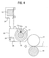
Fig. 4} Fig. 4 shows a cross-sectional view taken along a line IV-IV inFig. 1 and seen in the direction of arrows IV inFig. 1 ; - {
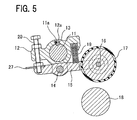
FIG. 5} Fig. 5 shows a view of a retreat state corresponding toFig. 2 ; and - {
FIG. 6} Fig. 6 shows a view of the retreat state corresponding toFig. 3 . - An embodiment of a multi-feed detection device according to the present invention will be described with reference to the drawings. Note that the multi-feed detection device according to the present invention is not limited to the following embodiment to be described with reference to the drawings.
- A main embodiment of the multi-feed detection device according to the present invention will be described with reference to
Figs. 1 to 6 . - As shown in
Figs. 1 to 4 , above the path line of atraveling sheet 1, there is asupport shaft 11 supported in such a way as to be capable of being turnably driven. Thesupport shaft 11 has its axial direction set in a horizontal direction (the top-bottom direction inFig. 1 ; the direction perpendicular to the surface ofFigs. 2 to 4 ) which is perpendicular to the feed (travel) direction (the right-left direction inFigs. 1 to 4 ) of thesheet 1. Akeyway 11a is formed in the outer peripheral surface of thesupport shaft 11 in the axial direction of thesupport shaft 11. - As shown in
Figs. 1 and2 , abracket 12 is fitted to the outer peripheral surface of thesupport shaft 11. Akeyway 12a is formed in the inner peripheral surface of thebracket 12 fitted to the outer peripheral surface of thesupport shaft 11, in the axial direction of thesupport shaft 11. Akey 13 is fitted in thekeyways support shaft 11 and thebracket 12. Thus, thesupport shaft 11 can be turned along with thebracket 12 by use of thekey 13. - An
arm 15 with its longitudinal direction set in the feed (travel) direction of the sheet 1 (the right-left direction inFigs. 1 and2 ) is swingably supported, at its middle portion, on thebracket 12 through apin 14. Awheel 17 with its axial direction set in the axial direction of thesupport shaft 11 is rotatably supported on an upstream side of thearm 15 in the feed (travel) direction of the sheet 1 (the right side inFigs. 1 and2 ) through apin 16. The outer peripheral surface of thiswheel 17 is made of rubber. - A
roller 18 with its axial direction set in the axial direction of thesupport shaft 11 is supported in such a way as to be capable of being rotationally driven, at a position below the path line of thesheet 1 under thewheel 17. Acompression coil spring 19 being biasing means for biasing thewheel 17 toward theroller 18, i.e. in a direction to bring thewheel 17 into contact with thesheet 1 in the thickness direction thereof, is inserted between thebracket 12 and thearm 15 between thepin 14 and thewheel 17. - An
adjustment screw 20 being adjusting means to be screwed in thebracket 12 has a tip side thereof in contact with the upper surface of thearm 15 on a downstream side in the feed direction of the sheet 1 (the left side inFigs. 1 and2 ). By adjusting the screwed position of theadjustment screw 20 in thebracket 12, it is possible to adjust the compressive force of thewheel 17 against theroller 18, i.e. the contact pressure of thewheel 17 in the thickness direction of thesheet 1. - As shown in
Figs. 1 ,3 , and4 , asleeve 21 is fitted to the outer peripheral surface of thesupport shaft 11. A keyway 22a configured to be fitted to theaforementioned key 13 is formed in the inner peripheral surface of thesleeve 21 fitted to the outer peripheral surface of thesupport shaft 11. The inner peripheral surfaces ofbearings 22 are coaxially fitted to the outer peripheral surface of thesleeve 21. - A
holder 23 fixedly supported on astay 101, which is fixed to a main frame, through acoupling member 24 is fitted to the outer peripheral surface of each bearing 22. This holder 23 rotatably supports thesupport shaft 11 through thebearings 22 and thesleeve 21. In other words, theholder 23 is fixedly supported on thestay 101 through thecoupling member 24 and also rotatably attached to thesupport shaft 11 through thebearings 22 and thesleeve 21, so as not to be turned by turn of thesupport shaft 11. - A
non-contact sensor 26 being non-contact measuring means including laser-light emitting part and laser-light receiving part is attached to the lower surface of theholder 23 on a downstream side in the feed (travel) direction of the sheet 1 (the left side inFigs. 1 ,3 , and4 ) through anattachment member 25 with the light emitting part and the light receiving part facing downward. - As shown in
Fig. 2 , adetection plate 27 being a target to reflect laser light is attached to the upper surface of thearm 15 on the downstream side in the feed (travel) direction of the sheet 1 (the left side inFig. 2 ) while extending to be situated under the non-contact sensor 26 (seeFigs. 1 and3 ). - Moreover, the
non-contact sensor 26 is electrically connected to an input part and an output part of an unillustrated control device being controlling means. This control device can find the positional relation (distance) between thenon-contact sensor 26 and thedetection plate 27 on the basis of information from thenon-contact sensor 26 obtained by causing the light emitting part of thenon-contact sensor 26 to emit laser light, and causing the light receiving part to receive the laser light reflected on thedetection plate 27. - Note that reference signs 28 in
Fig. 1 denote hollow set screws that fix the key 13 to thesupport shaft 11. - In this embodiment as above, the
bracket 12, the key 13, thehollow set screws 28, etc. form a bracket member; thepin 14, thearm 15, thepin 16, thewheel 17, etc. form an arm member; the key 13, thesleeve 21, thebearings 22, theholder 23, thecoupling member 24, and thehollow set screws 28, etc. form a holder member; and theattachment member 25, thenon-contact sensor 26, thedetection plate 27, etc. form detecting means. - In a
multi-feed detection device 10 according to this embodiment configured as above, the screwed position of theadjustment screw 20 in thebracket 12 is firstly adjusted based on conditions such as the thickness of thesheet 1, so as to adjust the compressive force of thewheel 17 against theroller 18, i.e. the contact pressure of thewheel 17 in the thickness direction of thesheet 1 in advance. - Then,
stacked sheets 1 are sequentially fed and travel between thewheel 17 and theroller 18. Thewheel 17 rises, against the biasing force of thecompression coil spring 19, by a distance corresponding to the thickness of thesheet 1 traveling between thewheel 17 and theroller 18. In response to this, thearm 15 swings, and thedetection plate 27 thus lowers, hence changing the positional relation (distance) between thenon-contact sensor 26 and thedetection plate 27. - In this event, the control device finds the positional relation (distance) between the
non-contact sensor 26 and thedetection plate 27 on the basis of the information from thenon-contact sensor 26, which is obtained by causing the light emitting part of thenon-contact sensor 26 to emit laser light, and causing the light receiving part of thenon-contact sensor 26 to receive the laser light reflected on thedetection plate 27. - Based on the positional relation, the control device determines whether or not a plurality of the
sheets 1 are accidentally overlapped and fed. If determining that a plurality of thesheets 1 are accidentally overlapped and fed, the control device temporarily stops the feed of thestacked sheets 1. - Then, as shown in
Fig. 5 , thesupport shaft 11 is turned (counterclockwise inFig. 5 ). In this way, thewheel 17 can be separated from theroller 18 and moved to a retreat position without causing any contact between thedetection plate 27 and the non-contact sensor 26 (seeFig. 6 ). Thesheets 1 in the gap between thewheel 17 and theroller 18 can now be removed from the gap easily. - Once the
sheets 1 are removed from the gap, thesupport shaft 11 is turned (clockwise inFig. 5 ) to bring thewheel 17 into contact with theroller 18 and move thewheel 17 to an operation position at which thewheel 17 contacts asheet 1. One of thesheets 1 removed from the gap is returned to the original position to reuse thesheets 1. - As described above, in the case of a sheet-fed printing press, a plurality of sheets are prevented from being overlapped and fed from a sheet feed apparatus to a printing unit. Thus, it is possible to suppress the occurrence of printing defects and thus significantly reduce wasted sheets.
- Specifically, the
multi-feed detection device 10 according to this embodiment is configured such that thenon-contact sensor 26 is used to find the positional relation (distance) between it and thedetection plate 27, thereby allowing non-contact detection of whether or not a plurality of thesheets 1 are accidentally overlapped and fed. - Hence, in the
multi-feed detection device 10 according to this embodiment, errors are less likely to occur in the detection of the positional relation between thenon-contact sensor 26 and thedetection plate 27 by thenon-contact sensor 26 even after long-term use. Accordingly, it is possible to reduce the time and effort required for periodic maintenance, inspection, and the like. - In the foregoing embodiment, the description has been given on the case where the
wheel 17 provided rotatably on the upstream side of thearm 15 in the feed (travel) direction of thesheet 1 comes into contact with thesheet 1. Note, however, that it is possible to employ an arm member that allows sliding contact with the travelingsheet 1, for example, as another embodiment. - Moreover, in the foregoing embodiment, the description has been given on the case where the
non-contact sensor 26 is attached to theholder 23, and thedetection plate 27 is attached to thearm 15. However, it is possible to attach thedetection plate 27 to theholder 23 and attach thenon-contact sensor 26 to thearm 15, for example, as another embodiment. - Moreover, in the foregoing embodiment, the positional relation (distance) between the
non-contact sensor 26 and thedetection plate 27 is detected in a non-contact manner by causing thenon-contact sensor 26 to emit laser light and causing thenon-contact sensor 26 to receive the laser light reflected on thedetection plate 27. However, the present invention is not limited to this case. A similar effect to that of the foregoing embodiment can be achieved as long as using non-contact measuring means for measuring, in a non-contact manner, the positional relation between it and a target, the positional relation being changed by swing of the arm member. - Moreover, the multi-feed detection device according to the present invention can be applied, of course, to a case as described in the Background Art where sheets are fed one by one from a sheet feed apparatus of a sheet-fed printing press to a printing unit thereof and subjected to printing. The multi-feed detection device according to the present invention can be applied to any case as long as it involves detection of a plurality of traveling sheets accidentally overlapped.
- The multi-feed detection device according to the present invention can reduce the time and effort required for periodic maintenance, inspection, and the like. Accordingly, the multi-feed detection device according to the present invention can be utilized significantly effectively in various industries including printing industries.
-
{Reference Signs List} 1 SHEET 10 MULTI-FEED DETECTION DEVICE 11 SUPPORT SHAFT 11a KEYWAY 12 BRACKET 12a KEYWAY 13 KEY 14 PIN 15 ARM 16 PIN 17 WHEEL 18 ROLLER 19 COMPRESSION COIL SPRING 20 ADJUSTMENT SCREW 21 SLEEVE 21a KEYWAY 22 BEARING 23 HOLDER 24 COUPLING MEMBER 25 ATTACHMENT MEMBER 26 NON-CONTACT SENSOR 27 DETECTION PLATE 28 HOLLOW SET SCREW 101 STAY
Claims (3)
- A multi-feed detection device including:an arm member (14 to 17) supported swingably and configured to come into contact with a traveling sheet (1) ; anddetecting means (25 to 27) for detecting whether a plurality of the traveling sheets (1) are overlapped and fed, on the basis of swing of the arm member (14 to 17), the multi-feed detection device characterized in thatthe detecting means (25 to 27) includes a target (27), andnon-contact measuring means (26) for measuring, in a non-contact manner, a positional relation between the non-contact measuring means (26) and the target (27), the positional relation being changed by swing of the arm member (14 to 17).
- The multi-feed detection device according to claim 1, characterized in that the multi-feed detection device further comprises:a bracket member (12, 13, 28) swingably supporting the arm member (14 to 17);a turnable support shaft (11) supporting the bracket member (12, 13, 28) and configured to turn the bracket member (12, 13, 28) ; anda holder member (13, 21 to 24, 28) rotatably attached to the support shaft (11) and fixedly supported so as not to be turned by turn of the support shaft (11), andthe target (27) of the detecting means (25 to 27) is provided to the arm member (14 to 17),the non-contact measuring means (26) of the detecting means (25 to 27) is provided to the holder member (13, 21 to 24, 28), andthe support shaft (11) is configured to be turned in such a way as to move the arm member (14 to 17) between an operation position at which the arm member (14 to 17) comes into contact with the sheet (1) and a retreat position at which the arm member (14 to 17) is separated from the sheet (1).
- The multi-feed detection device according to claim 2, characterized in that the multi-feed detection device further comprises:biasing means (19) for biasing the arm member (14 to 17) in a direction to contact the sheet (1), the biasing means (19) being arranged between the arm member (14 to 17) and the bracket member (12, 13, 28) ; andadjusting means (20) for adjusting contact pressure of the arm member (14 to 17) against the sheet (1).
Applications Claiming Priority (1)
| Application Number | Priority Date | Filing Date | Title |
|---|---|---|---|
| JP2012102425A JP5988289B2 (en) | 2012-04-27 | 2012-04-27 | Sheet overlap feed detection device |
Publications (3)
| Publication Number | Publication Date |
|---|---|
| EP2657165A2 true EP2657165A2 (en) | 2013-10-30 |
| EP2657165A3 EP2657165A3 (en) | 2015-12-09 |
| EP2657165B1 EP2657165B1 (en) | 2017-04-12 |
Family
ID=48430450
Family Applications (1)
| Application Number | Title | Priority Date | Filing Date |
|---|---|---|---|
| EP13165400.6A Active EP2657165B1 (en) | 2012-04-27 | 2013-04-25 | Multi-feed detection device |
Country Status (4)
| Country | Link |
|---|---|
| US (1) | US8833762B2 (en) |
| EP (1) | EP2657165B1 (en) |
| JP (1) | JP5988289B2 (en) |
| CN (1) | CN103373622B (en) |
Cited By (2)
| Publication number | Priority date | Publication date | Assignee | Title |
|---|---|---|---|---|
| WO2016062411A1 (en) * | 2014-10-24 | 2016-04-28 | Bobst Mex Sa | Device for laterally positioning a plate element |
| WO2017207111A1 (en) * | 2016-05-30 | 2017-12-07 | Bobst Mex Sa | Detection system for detecting double sheets in a sheet element processing machine, and sheet element processing machine |
Families Citing this family (3)
| Publication number | Priority date | Publication date | Assignee | Title |
|---|---|---|---|---|
| KR101940296B1 (en) * | 2012-10-09 | 2019-01-21 | 에이치피프린팅코리아 유한회사 | Paper-feeding apparatus and image forming apparatus adopting the same |
| CN105691756A (en) * | 2016-04-05 | 2016-06-22 | 亚龙纸制品(昆山)有限公司 | Automatic fold detecting device |
| CN112850075B (en) * | 2020-12-28 | 2022-12-20 | 湖北航鹏化学动力科技有限责任公司 | Automatic production line conveying mechanism |
Citations (2)
| Publication number | Priority date | Publication date | Assignee | Title |
|---|---|---|---|---|
| JPH0351248A (en) | 1989-04-06 | 1991-03-05 | Komori Corp | Paper feed safety device for sheet paper printing machine and clearance adjusting method for this device |
| JP2517227Y2 (en) | 1991-11-22 | 1996-11-20 | 株式会社小森コーポレーション | Double-sheet feeding detection device for sheet-fed rotary printing |
Family Cites Families (14)
| Publication number | Priority date | Publication date | Assignee | Title |
|---|---|---|---|---|
| US2637552A (en) * | 1952-04-01 | 1953-05-05 | Christensen Machine Co | Magnetic caliper for sheet material handling apparatus |
| US2890884A (en) * | 1953-10-12 | 1959-06-16 | Lewfor Dev Corp | Multiple sheet electing mechanism |
| JPS5727847A (en) * | 1980-07-23 | 1982-02-15 | Omron Tateisi Electronics Co | Multi-feed detector of sheet |
| DE3823201A1 (en) * | 1988-07-08 | 1988-12-08 | Mabeg Maschinenbau Gmbh Nachf | Multiple sheet monitoring device |
| JPH06115762A (en) * | 1992-10-05 | 1994-04-26 | Shinohara Tekkosho:Kk | Multifeed detecting device for sheet |
| US6000693A (en) * | 1995-12-05 | 1999-12-14 | Unisys Corporation | Article detection via pinch-roll motion |
| US6734417B2 (en) * | 2002-05-08 | 2004-05-11 | Hewlett-Packard Development Company, L.P. | Displacement measurement system and sheet feed system incorporating the same |
| KR20040031935A (en) * | 2002-10-07 | 2004-04-14 | 엘지엔시스(주) | Cash thickness detecting apparatus for cash auto dispenser |
| KR20060073674A (en) * | 2004-12-24 | 2006-06-28 | 노틸러스효성 주식회사 | Feeder overlap feed detection device and method |
| US7817957B2 (en) * | 2005-07-08 | 2010-10-19 | Ricoh Company, Ltd. | Double feed sensing device, double feed determining method and image forming apparatus |
| ATE543763T1 (en) * | 2007-08-31 | 2012-02-15 | Glory Kogyo Kk | PAPER THICKNESS DETECTION DEVICE |
| JP5546288B2 (en) * | 2010-02-26 | 2014-07-09 | キヤノン株式会社 | Sheet thickness detection apparatus, image forming apparatus, and sheet feeding apparatus |
| JP5553647B2 (en) * | 2010-02-26 | 2014-07-16 | キヤノン株式会社 | Sheet thickness detection apparatus and image forming apparatus |
| JP5561082B2 (en) * | 2010-10-07 | 2014-07-30 | 沖電気工業株式会社 | Opening and closing mechanism of paper sheet thickness detector |
-
2012
- 2012-04-27 JP JP2012102425A patent/JP5988289B2/en active Active
-
2013
- 2013-04-24 CN CN201310146006.5A patent/CN103373622B/en active Active
- 2013-04-25 EP EP13165400.6A patent/EP2657165B1/en active Active
- 2013-04-26 US US13/871,474 patent/US8833762B2/en active Active
Patent Citations (2)
| Publication number | Priority date | Publication date | Assignee | Title |
|---|---|---|---|---|
| JPH0351248A (en) | 1989-04-06 | 1991-03-05 | Komori Corp | Paper feed safety device for sheet paper printing machine and clearance adjusting method for this device |
| JP2517227Y2 (en) | 1991-11-22 | 1996-11-20 | 株式会社小森コーポレーション | Double-sheet feeding detection device for sheet-fed rotary printing |
Cited By (6)
| Publication number | Priority date | Publication date | Assignee | Title |
|---|---|---|---|---|
| WO2016062411A1 (en) * | 2014-10-24 | 2016-04-28 | Bobst Mex Sa | Device for laterally positioning a plate element |
| US10005631B2 (en) | 2014-10-24 | 2018-06-26 | Bobst Mex Sa | Lateral positioning device for a sheet element |
| WO2017207111A1 (en) * | 2016-05-30 | 2017-12-07 | Bobst Mex Sa | Detection system for detecting double sheets in a sheet element processing machine, and sheet element processing machine |
| CN109311614A (en) * | 2016-05-30 | 2019-02-05 | 鲍勃斯脱梅克斯股份有限公司 | Inspection system and sheet element processor for inspecting double sheets in a sheet element processor |
| US10640314B2 (en) | 2016-05-30 | 2020-05-05 | Bobst Mex Sa | Detection system for detecting double sheets in a sheet element processing machine, and sheet element processing machine |
| CN109311614B (en) * | 2016-05-30 | 2020-08-14 | 鲍勃斯脱梅克斯股份有限公司 | Detection system for detecting double sheets in a sheet element processing machine and sheet element processing machine |
Also Published As
| Publication number | Publication date |
|---|---|
| EP2657165A3 (en) | 2015-12-09 |
| JP5988289B2 (en) | 2016-09-07 |
| US20130285319A1 (en) | 2013-10-31 |
| JP2013230878A (en) | 2013-11-14 |
| CN103373622A (en) | 2013-10-30 |
| CN103373622B (en) | 2016-10-19 |
| EP2657165B1 (en) | 2017-04-12 |
| US8833762B2 (en) | 2014-09-16 |
Similar Documents
| Publication | Publication Date | Title |
|---|---|---|
| US8833762B2 (en) | Multi-feed detection device | |
| JP6198313B2 (en) | Rotary punching machine | |
| KR20100044386A (en) | Thickness measuring device of steel sheet | |
| US10654085B2 (en) | Apparatus and method to guide metal products | |
| EP2058251A3 (en) | Skew Adjustment of Print Sheets | |
| WO2009133832A1 (en) | Brittle material breaking apparatus and brittle material breaking method | |
| JP2003182931A (en) | Method for adjusting the folding gap width of a plurality of folding roller pairs and folding machine for adjusting the folding gap width | |
| KR20080005094U (en) | Detection structure of the transport device | |
| CN204588227U (en) | Guillotine | |
| CN110645944A (en) | Online thickness measuring system for ultra-wide PC sheet | |
| KR101410205B1 (en) | The Abnormality detection system of Material feed device for gantry to Feed roller and rail status | |
| US10005631B2 (en) | Lateral positioning device for a sheet element | |
| JP6094341B2 (en) | Material feeder | |
| JP2014518773A (en) | Measuring device, roll stand and method for detecting the height of a roll gap | |
| JP2017090265A (en) | Sheet thickness measurement device | |
| KR102117778B1 (en) | Sheet element processing machine and detection system for detecting double sheets in the sheet element processing machine | |
| US20050239624A1 (en) | Folding unit having a folding roller adjustment means | |
| US1040168A (en) | Sheet-registering mechanism for paper-feeding machines. | |
| CN202448479U (en) | Ultrasonic double-sheet detecting device of printing machine | |
| KR101320289B1 (en) | Pinch roll device | |
| CN110980389B (en) | A sheet cutting device | |
| KR100984441B1 (en) | Stopper device for cutting steel sheet | |
| US2517379A (en) | Multiple sheet detector mechanism for use with sheet-feeding apparatus | |
| CN205081767U (en) | Proximity switch with soft contact of metal detecting body adoption | |
| JP2009161313A (en) | Double feed state detector of paper sheet printer |
Legal Events
| Date | Code | Title | Description |
|---|---|---|---|
| PUAI | Public reference made under article 153(3) epc to a published international application that has entered the european phase |
Free format text: ORIGINAL CODE: 0009012 |
|
| AK | Designated contracting states |
Kind code of ref document: A2 Designated state(s): AL AT BE BG CH CY CZ DE DK EE ES FI FR GB GR HR HU IE IS IT LI LT LU LV MC MK MT NL NO PL PT RO RS SE SI SK SM TR |
|
| AX | Request for extension of the european patent |
Extension state: BA ME |
|
| PUAL | Search report despatched |
Free format text: ORIGINAL CODE: 0009013 |
|
| AK | Designated contracting states |
Kind code of ref document: A3 Designated state(s): AL AT BE BG CH CY CZ DE DK EE ES FI FR GB GR HR HU IE IS IT LI LT LU LV MC MK MT NL NO PL PT RO RS SE SI SK SM TR |
|
| AX | Request for extension of the european patent |
Extension state: BA ME |
|
| RIC1 | Information provided on ipc code assigned before grant |
Ipc: B65H 7/12 20060101AFI20151102BHEP |
|
| 17P | Request for examination filed |
Effective date: 20160608 |
|
| RBV | Designated contracting states (corrected) |
Designated state(s): AL AT BE BG CH CY CZ DE DK EE ES FI FR GB GR HR HU IE IS IT LI LT LU LV MC MK MT NL NO PL PT RO RS SE SI SK SM TR |
|
| GRAP | Despatch of communication of intention to grant a patent |
Free format text: ORIGINAL CODE: EPIDOSNIGR1 |
|
| INTG | Intention to grant announced |
Effective date: 20161019 |
|
| GRAS | Grant fee paid |
Free format text: ORIGINAL CODE: EPIDOSNIGR3 |
|
| GRAA | (expected) grant |
Free format text: ORIGINAL CODE: 0009210 |
|
| AK | Designated contracting states |
Kind code of ref document: B1 Designated state(s): AL AT BE BG CH CY CZ DE DK EE ES FI FR GB GR HR HU IE IS IT LI LT LU LV MC MK MT NL NO PL PT RO RS SE SI SK SM TR |
|
| REG | Reference to a national code |
Ref country code: GB Ref legal event code: FG4D |
|
| REG | Reference to a national code |
Ref country code: CH Ref legal event code: EP Ref country code: CH Ref legal event code: NV Representative=s name: R.A. EGLI AND CO, PATENTANWAELTE, CH |
|
| REG | Reference to a national code |
Ref country code: NL Ref legal event code: FP |
|
| REG | Reference to a national code |
Ref country code: FR Ref legal event code: PLFP Year of fee payment: 5 |
|
| REG | Reference to a national code |
Ref country code: IE Ref legal event code: FG4D |
|
| REG | Reference to a national code |
Ref country code: AT Ref legal event code: REF Ref document number: 883634 Country of ref document: AT Kind code of ref document: T Effective date: 20170515 |
|
| REG | Reference to a national code |
Ref country code: DE Ref legal event code: R096 Ref document number: 602013019652 Country of ref document: DE |
|
| REG | Reference to a national code |
Ref country code: LT Ref legal event code: MG4D |
|
| REG | Reference to a national code |
Ref country code: AT Ref legal event code: MK05 Ref document number: 883634 Country of ref document: AT Kind code of ref document: T Effective date: 20170412 |
|
| PG25 | Lapsed in a contracting state [announced via postgrant information from national office to epo] |
Ref country code: HR Free format text: LAPSE BECAUSE OF FAILURE TO SUBMIT A TRANSLATION OF THE DESCRIPTION OR TO PAY THE FEE WITHIN THE PRESCRIBED TIME-LIMIT Effective date: 20170412 Ref country code: GR Free format text: LAPSE BECAUSE OF FAILURE TO SUBMIT A TRANSLATION OF THE DESCRIPTION OR TO PAY THE FEE WITHIN THE PRESCRIBED TIME-LIMIT Effective date: 20170713 Ref country code: AT Free format text: LAPSE BECAUSE OF FAILURE TO SUBMIT A TRANSLATION OF THE DESCRIPTION OR TO PAY THE FEE WITHIN THE PRESCRIBED TIME-LIMIT Effective date: 20170412 Ref country code: LT Free format text: LAPSE BECAUSE OF FAILURE TO SUBMIT A TRANSLATION OF THE DESCRIPTION OR TO PAY THE FEE WITHIN THE PRESCRIBED TIME-LIMIT Effective date: 20170412 Ref country code: ES Free format text: LAPSE BECAUSE OF FAILURE TO SUBMIT A TRANSLATION OF THE DESCRIPTION OR TO PAY THE FEE WITHIN THE PRESCRIBED TIME-LIMIT Effective date: 20170412 Ref country code: FI Free format text: LAPSE BECAUSE OF FAILURE TO SUBMIT A TRANSLATION OF THE DESCRIPTION OR TO PAY THE FEE WITHIN THE PRESCRIBED TIME-LIMIT Effective date: 20170412 Ref country code: NO Free format text: LAPSE BECAUSE OF FAILURE TO SUBMIT A TRANSLATION OF THE DESCRIPTION OR TO PAY THE FEE WITHIN THE PRESCRIBED TIME-LIMIT Effective date: 20170712 |
|
| PG25 | Lapsed in a contracting state [announced via postgrant information from national office to epo] |
Ref country code: LV Free format text: LAPSE BECAUSE OF FAILURE TO SUBMIT A TRANSLATION OF THE DESCRIPTION OR TO PAY THE FEE WITHIN THE PRESCRIBED TIME-LIMIT Effective date: 20170412 Ref country code: RS Free format text: LAPSE BECAUSE OF FAILURE TO SUBMIT A TRANSLATION OF THE DESCRIPTION OR TO PAY THE FEE WITHIN THE PRESCRIBED TIME-LIMIT Effective date: 20170412 Ref country code: PL Free format text: LAPSE BECAUSE OF FAILURE TO SUBMIT A TRANSLATION OF THE DESCRIPTION OR TO PAY THE FEE WITHIN THE PRESCRIBED TIME-LIMIT Effective date: 20170412 Ref country code: SE Free format text: LAPSE BECAUSE OF FAILURE TO SUBMIT A TRANSLATION OF THE DESCRIPTION OR TO PAY THE FEE WITHIN THE PRESCRIBED TIME-LIMIT Effective date: 20170412 Ref country code: BG Free format text: LAPSE BECAUSE OF FAILURE TO SUBMIT A TRANSLATION OF THE DESCRIPTION OR TO PAY THE FEE WITHIN THE PRESCRIBED TIME-LIMIT Effective date: 20170712 Ref country code: IS Free format text: LAPSE BECAUSE OF FAILURE TO SUBMIT A TRANSLATION OF THE DESCRIPTION OR TO PAY THE FEE WITHIN THE PRESCRIBED TIME-LIMIT Effective date: 20170812 |
|
| REG | Reference to a national code |
Ref country code: DE Ref legal event code: R097 Ref document number: 602013019652 Country of ref document: DE |
|
| REG | Reference to a national code |
Ref country code: IE Ref legal event code: MM4A |
|
| PG25 | Lapsed in a contracting state [announced via postgrant information from national office to epo] |
Ref country code: SK Free format text: LAPSE BECAUSE OF FAILURE TO SUBMIT A TRANSLATION OF THE DESCRIPTION OR TO PAY THE FEE WITHIN THE PRESCRIBED TIME-LIMIT Effective date: 20170412 Ref country code: RO Free format text: LAPSE BECAUSE OF FAILURE TO SUBMIT A TRANSLATION OF THE DESCRIPTION OR TO PAY THE FEE WITHIN THE PRESCRIBED TIME-LIMIT Effective date: 20170412 Ref country code: CZ Free format text: LAPSE BECAUSE OF FAILURE TO SUBMIT A TRANSLATION OF THE DESCRIPTION OR TO PAY THE FEE WITHIN THE PRESCRIBED TIME-LIMIT Effective date: 20170412 Ref country code: DK Free format text: LAPSE BECAUSE OF FAILURE TO SUBMIT A TRANSLATION OF THE DESCRIPTION OR TO PAY THE FEE WITHIN THE PRESCRIBED TIME-LIMIT Effective date: 20170412 Ref country code: MC Free format text: LAPSE BECAUSE OF FAILURE TO SUBMIT A TRANSLATION OF THE DESCRIPTION OR TO PAY THE FEE WITHIN THE PRESCRIBED TIME-LIMIT Effective date: 20170412 Ref country code: EE Free format text: LAPSE BECAUSE OF FAILURE TO SUBMIT A TRANSLATION OF THE DESCRIPTION OR TO PAY THE FEE WITHIN THE PRESCRIBED TIME-LIMIT Effective date: 20170412 |
|
| PLBE | No opposition filed within time limit |
Free format text: ORIGINAL CODE: 0009261 |
|
| STAA | Information on the status of an ep patent application or granted ep patent |
Free format text: STATUS: NO OPPOSITION FILED WITHIN TIME LIMIT |
|
| PG25 | Lapsed in a contracting state [announced via postgrant information from national office to epo] |
Ref country code: IT Free format text: LAPSE BECAUSE OF FAILURE TO SUBMIT A TRANSLATION OF THE DESCRIPTION OR TO PAY THE FEE WITHIN THE PRESCRIBED TIME-LIMIT Effective date: 20170412 Ref country code: LU Free format text: LAPSE BECAUSE OF NON-PAYMENT OF DUE FEES Effective date: 20170425 Ref country code: SM Free format text: LAPSE BECAUSE OF FAILURE TO SUBMIT A TRANSLATION OF THE DESCRIPTION OR TO PAY THE FEE WITHIN THE PRESCRIBED TIME-LIMIT Effective date: 20170412 |
|
| REG | Reference to a national code |
Ref country code: FR Ref legal event code: PLFP Year of fee payment: 6 |
|
| 26N | No opposition filed |
Effective date: 20180115 |
|
| REG | Reference to a national code |
Ref country code: BE Ref legal event code: MM Effective date: 20170430 |
|
| PG25 | Lapsed in a contracting state [announced via postgrant information from national office to epo] |
Ref country code: IE Free format text: LAPSE BECAUSE OF NON-PAYMENT OF DUE FEES Effective date: 20170425 |
|
| PGFP | Annual fee paid to national office [announced via postgrant information from national office to epo] |
Ref country code: GB Payment date: 20180329 Year of fee payment: 6 Ref country code: NL Payment date: 20180314 Year of fee payment: 6 |
|
| PG25 | Lapsed in a contracting state [announced via postgrant information from national office to epo] |
Ref country code: SI Free format text: LAPSE BECAUSE OF FAILURE TO SUBMIT A TRANSLATION OF THE DESCRIPTION OR TO PAY THE FEE WITHIN THE PRESCRIBED TIME-LIMIT Effective date: 20170412 Ref country code: BE Free format text: LAPSE BECAUSE OF NON-PAYMENT OF DUE FEES Effective date: 20170430 |
|
| PGFP | Annual fee paid to national office [announced via postgrant information from national office to epo] |
Ref country code: FR Payment date: 20180315 Year of fee payment: 6 |
|
| PGFP | Annual fee paid to national office [announced via postgrant information from national office to epo] |
Ref country code: CH Payment date: 20180416 Year of fee payment: 6 |
|
| PG25 | Lapsed in a contracting state [announced via postgrant information from national office to epo] |
Ref country code: MT Free format text: LAPSE BECAUSE OF NON-PAYMENT OF DUE FEES Effective date: 20170425 |
|
| PG25 | Lapsed in a contracting state [announced via postgrant information from national office to epo] |
Ref country code: HU Free format text: LAPSE BECAUSE OF FAILURE TO SUBMIT A TRANSLATION OF THE DESCRIPTION OR TO PAY THE FEE WITHIN THE PRESCRIBED TIME-LIMIT; INVALID AB INITIO Effective date: 20130425 |
|
| PG25 | Lapsed in a contracting state [announced via postgrant information from national office to epo] |
Ref country code: CY Free format text: LAPSE BECAUSE OF NON-PAYMENT OF DUE FEES Effective date: 20170412 |
|
| PG25 | Lapsed in a contracting state [announced via postgrant information from national office to epo] |
Ref country code: MK Free format text: LAPSE BECAUSE OF FAILURE TO SUBMIT A TRANSLATION OF THE DESCRIPTION OR TO PAY THE FEE WITHIN THE PRESCRIBED TIME-LIMIT Effective date: 20170412 |
|
| REG | Reference to a national code |
Ref country code: CH Ref legal event code: PL |
|
| REG | Reference to a national code |
Ref country code: NL Ref legal event code: MM Effective date: 20190501 |
|
| GBPC | Gb: european patent ceased through non-payment of renewal fee |
Effective date: 20190425 |
|
| PG25 | Lapsed in a contracting state [announced via postgrant information from national office to epo] |
Ref country code: CH Free format text: LAPSE BECAUSE OF NON-PAYMENT OF DUE FEES Effective date: 20190430 Ref country code: GB Free format text: LAPSE BECAUSE OF NON-PAYMENT OF DUE FEES Effective date: 20190425 Ref country code: NL Free format text: LAPSE BECAUSE OF NON-PAYMENT OF DUE FEES Effective date: 20190501 Ref country code: LI Free format text: LAPSE BECAUSE OF NON-PAYMENT OF DUE FEES Effective date: 20190430 |
|
| PG25 | Lapsed in a contracting state [announced via postgrant information from national office to epo] |
Ref country code: FR Free format text: LAPSE BECAUSE OF NON-PAYMENT OF DUE FEES Effective date: 20190430 |
|
| PG25 | Lapsed in a contracting state [announced via postgrant information from national office to epo] |
Ref country code: TR Free format text: LAPSE BECAUSE OF FAILURE TO SUBMIT A TRANSLATION OF THE DESCRIPTION OR TO PAY THE FEE WITHIN THE PRESCRIBED TIME-LIMIT Effective date: 20170412 |
|
| PG25 | Lapsed in a contracting state [announced via postgrant information from national office to epo] |
Ref country code: PT Free format text: LAPSE BECAUSE OF FAILURE TO SUBMIT A TRANSLATION OF THE DESCRIPTION OR TO PAY THE FEE WITHIN THE PRESCRIBED TIME-LIMIT Effective date: 20170412 |
|
| PG25 | Lapsed in a contracting state [announced via postgrant information from national office to epo] |
Ref country code: AL Free format text: LAPSE BECAUSE OF FAILURE TO SUBMIT A TRANSLATION OF THE DESCRIPTION OR TO PAY THE FEE WITHIN THE PRESCRIBED TIME-LIMIT Effective date: 20170412 |
|
| PGFP | Annual fee paid to national office [announced via postgrant information from national office to epo] |
Ref country code: DE Payment date: 20250305 Year of fee payment: 13 |