EP2659940A1 - Toe piece for a mountaineering ski binding - Google Patents
Toe piece for a mountaineering ski binding Download PDFInfo
- Publication number
- EP2659940A1 EP2659940A1 EP13166182.9A EP13166182A EP2659940A1 EP 2659940 A1 EP2659940 A1 EP 2659940A1 EP 13166182 A EP13166182 A EP 13166182A EP 2659940 A1 EP2659940 A1 EP 2659940A1
- Authority
- EP
- European Patent Office
- Prior art keywords
- jaws
- component
- toe piece
- plate
- wedge
- Prior art date
- Legal status (The legal status is an assumption and is not a legal conclusion. Google has not performed a legal analysis and makes no representation as to the accuracy of the status listed.)
- Granted
Links
Images



Classifications
-
- A—HUMAN NECESSITIES
- A63—SPORTS; GAMES; AMUSEMENTS
- A63C—SKATES; SKIS; ROLLER SKATES; DESIGN OR LAYOUT OF COURTS, RINKS OR THE LIKE
- A63C9/00—Ski bindings
- A63C9/08—Ski bindings yieldable or self-releasing in the event of an accident, i.e. safety bindings
- A63C9/0807—Ski bindings yieldable or self-releasing in the event of an accident, i.e. safety bindings for both towing and downhill skiing
-
- A—HUMAN NECESSITIES
- A63—SPORTS; GAMES; AMUSEMENTS
- A63C—SKATES; SKIS; ROLLER SKATES; DESIGN OR LAYOUT OF COURTS, RINKS OR THE LIKE
- A63C9/00—Ski bindings
- A63C9/08—Ski bindings yieldable or self-releasing in the event of an accident, i.e. safety bindings
- A63C9/085—Ski bindings yieldable or self-releasing in the event of an accident, i.e. safety bindings with sole hold-downs, e.g. swingable
- A63C9/08507—Ski bindings yieldable or self-releasing in the event of an accident, i.e. safety bindings with sole hold-downs, e.g. swingable with a plurality of mobile jaws
- A63C9/08528—Ski bindings yieldable or self-releasing in the event of an accident, i.e. safety bindings with sole hold-downs, e.g. swingable with a plurality of mobile jaws pivoting about a longitudinal axis
-
- A—HUMAN NECESSITIES
- A63—SPORTS; GAMES; AMUSEMENTS
- A63C—SKATES; SKIS; ROLLER SKATES; DESIGN OR LAYOUT OF COURTS, RINKS OR THE LIKE
- A63C9/00—Ski bindings
- A63C9/08—Ski bindings yieldable or self-releasing in the event of an accident, i.e. safety bindings
- A63C9/086—Ski bindings yieldable or self-releasing in the event of an accident, i.e. safety bindings using parts which are fixed on the shoe of the user and are releasable from the ski binding
Definitions
- the present invention relates to the special technical sector of attachments for Alpine skiing, in particular the toe piece of the attachments.
- the toe piece of the invention comprises a plate, destined to be blocked to a ski, to which the central parts of two right-angled jaws are hinged, facing and symmetrical with respect to the longitudinal plane of symmetry of the plate.
- Pins one for each jaw, project from the internal surfaces of the upper sides of the jaws, which pins face one another and are arranged on a transversal plane.
- the heads of the lower sides of the jaws are connected, with an interposing of springs, to a hinge that is symmetrical with respect to the transversal plane.
- the hinge-spring assembly defines, for the two jaws, two open and closed end configurations, to which corresponding relatively high and low positions for the hinge.
- An intermediate point of a main lever is hinged to the plate, according to a transversal axis, a fork-shaped end of which main lever engages the hinge.
- a safety lever is scissor-hinged by means of a transversal pin to the portion of the main lever situated, with respect to the hinge point, on an opposite side with respect to the fork.
- the hinge is constituted by two elements, respectively male and female; each of the elements exhibits two transversally-orientated flanked holes.
- Holes are made in the heads of the lower sides of the jaws, the axes of which are arranged on the transversal planes on which lie the corresponding axes of the holes realized in the relative element of the hinge; the plugs functioning as a guide for the previously-interposed springs between the head and the element are freely inserted in the holes of the head of a jaw and in the corresponding holes of the relative element.
- edges of the holes made in the heads and the male and female element of the hinge are advantageously countersunk so as to prevent out-of-axis movements of the springs during the use of the toe-piece.
- the means enabling defining the open and closed configurations of the jaws comprise:
- Holes must also be provided in the heads of the jaws and the elements of the hinge.
- the pins, springs and elements must be assembled such as to connect the jaws to the hinge-spring assembly.
- the above means are constituted by a not-insignificant number of elements, include a series of operating steps (the realising of the holes) and an assembly which is quite complex; all of which impacts on the cost and overall weight of the toe-piece.
- Patent WO 2009/121187 describes a toe-piece for Alpine skiing comprising, according to the prior art, two jaws provided with corresponding pins for coupling with a ski boot, and a plurality of springs, associated to the jaws, such as to define an open and a closed configuration for the jaws.
- Document EP 2.392.388 describes an attachment for Alpine skiing comprising a plate, a pair of jaws to which a plurality of springs is associated, and a pair of levers for enabling passage of the jaws from a closed position to an open position, and vice versa.
- the aim of the invention is to provide a toe-piece which obviates the drawbacks in the prior art, and in which the means mutually connecting the lower heads of the jaws, such as to define for the jaws the end open and closed configurations, are constituted by a limited number of components, obtainable with technological operations which do not require perforating steps, which components are simply and rapidlyassemblable, and are such as to have a lower weight with respect to the means of the prior art while carrying out the same functions.
- a further aim of the invention is to provide a toe-piece which beyond satisfying the preceding aim is also functional and reliable.
- 1 denotes a plate destined to be blocked (using the holes 2 realised therein) to a ski, not illustrated.
- the plate laterally forms opposite pairs of prominences 4 which support longitudinal pins 4A with which the central parts of two right-angled jaws 3A, 3B are hinged, and are symmetrically orientated with respect to a longitudinal plane.
- Relative pins 7A, 7B, facing inwards, are blocked to the inner surfaces of the upper sides 6A, 6B of the jaws.
- the heads of the lower sides of the jaws are concavelyprofiled such as to define relative seatings S1, S2 that are symmetrical with respect to the longitudinal plane; the mutual distance between the surfaces delimiting the seatings decreases, proceeding from upstream towards downstream, i.e. in the sense of the arrow F ( figures 2A, 2B ).
- the seatings are destined to receive, in a complementary coupling, lateral walls P1, P2 of a wedge-shaped component 10.
- the plate 1 Upstream (with respect to the arrow F) of the supports of the prominences 4,the plate 1 exhibits a further pair of supports 8 which sustain a transversal pin 9 to which an intermediate point of a longitudinally-arranged main safety lever 11 is hinged; the internal end of the lever has a fork 12 shape, which engages the wedge-shaped component 10.
- the fork 12 contains elastic means 13; the internal abutment 12A of the fork constitutes an abutment for an end of the elastic means, the remaining end thereof interacts with the larger base 10A of the wedge-shaped component 10.
- a spring 16 is associated to the pin 14, which spring tends to mutually open the levers 11, 15.
- the safety lever 15 comprises an internal lower part 150 (i.e. facing towards the jaws) and an upper external part 151 (i.e. facing towards the end of the toe-piece).
- the lower internal part 150 of the safety lever 15 bears a transversal pin 17 which idly supports a wheel 18 provided such as to interact with the upper surface of the plate and, if required, with a tooth 19 conformed thereby (see figure 4 ).
- the heads of the jaws 3A, 3B and the wedge-shaped element 10 identify a hinge, constituted by a female part and a male part.
- the female part comprises the truncoconical path defined by the seatings S1, S2 fashioned in the heads of the jaws;
- the male part is constituted by the walls P1, P2 of the wedge-shaped component, the heads of the walls P1, P2 being orientated in a trunconical fashion.
- the spring 13 stabilises the coupling of the male part with the female part; the wedge-shaped component can make axial sliding motions, opposed or facilitated by the spring.
- the wedge-shaped component 10 is in the high position A (open configuration of the jaws).
- the distance between the heads of the jaws first reduces and then newly increases as soon as the aligning of the lower sides 5A, 5B of the jaws is passed through.
- the component 10 slides towards the spring in opposition to the elastic reaction (increased by the sliding) of the spring; once the alignment of the sides 5A, 5B has been passed, the component, 10, by action of the spring 13, slides in an opposite direction to the preceding direction.
- the spring 13 stabilises in each operating situation, i.e. the open and closed configurations of the jaws and the passage between the configurations, the coupling between the female part and the male part of the hinge.
- a variant is included which comprises the male part in the heads of the jaws (with the seatings S1, S2 curved externally) and, obviously, the female part of the component 10, i.e. with the walls P1, P2 having seatings for the whole extension thereof and recessed in an inwards direction.
- a possible alternative is obtained by realising the male part and the female part constituted by two sections, for example a section in which a wall P1 and the complementary seating S1 are obtained as in the accompanying figures, while the remaining part P2 and the seating S2 exhibit profiles according to the above-mentioned variant.
- the walls P1, P2 are realised with a prismatic profile, and the seatings S1, S2 are complementary to the profiles; for example the profile of the walls P1, P2 are spire-shaped, with the vertex facing externally, or in a split polygonal shape.
- a spherical component is used, subject to a spring, the housing of which is defined by two seatings fashioned in the heads of the jaws; obviously this spherical component is inserted in the fork 12 of the main lever 11.
- the operating means mutually connecting the heads of the jaws and which are functionally associated to the fork 12 of the main lever 11 are constituted by a wedge-shaped component 10 and by a spring 13; the only operations required consist in operations on the heads of the lower sides of the jaws such that they can be coupled with the component 10.
- the solution provided enables considerably reducing the number of the elements, which translates into a simplification of the assembly thereof, in a reduction of costs and in a reduction of the overall weight of the toe-piece.
- the component 10 comprises two longitudinal projections 101 arranged at the relative upper surface (i.e. the surface of the component 10 opposite the plate 1 when the toe-piece is in use).
- the longitudinal projections 101 are conformed such as to embrace the lateral edge of the wedge-shaped component 10 which is opposite the safety lever 15 (see in particular figure 7 ).
- the internal part 150 of the safety lever 15 comprises two portions, parallel to one another, which extend from the external part 151 of the safety lever 15, and between which the main lever 11 is positioned and hinged (see figure 7 ).
- each portion of the internal wall 150 comprises a first appendage 152, which faces the wedge-shaped component 10, and a second appendage 153.
- the internal part 150 of the safety lever 15 forms an upturned C-shaped profile, and the first appendage 152 and the second appendage 153 are arranged at the ends of the C.
- first appendage 152 of each portion is conformed such as to couple with a corresponding longitudinal projection 101 arranged on the wedge-shaped component 10 when the safety lever 15 is in the relative operating configuration (i.e. when the jaws are in the relative closed position, and the toe-piece is therefore in use).
- each longitudinal projection 101 exhibits a part having a curved profile (the part embracing the lateral edge of the wedge-shaped component 10), and each first appendage 152 exhibits a part with a recess complementarily-shaped to the curved profile of the longitudinal projection 101, such as to enable a reciprocal coupling (see in particular figures 8A and 9A ).
- the plate 1 bears two wheels 100 arranged such that they are each abutted by a second appendage 153 of the safety lever 15.
- the wheels 100 are borne idle by corresponding pins 111 (transversal, in the case illustrated in the figures) fixed to the plate 1, provided with appropriate holes.
- each second appendage 153 abuts the corresponding wheel 100 in each situation, i.e. both when the jaws are in the open configuration thereof and when they are in the relative closed position.
- This variant advantageously significantly increases the stability of the toe-piece (and in particular the safety lever 15) when in use, i.e. when the jaws are in the relative closed position.
Landscapes
- Carriages For Children, Sleds, And Other Hand-Operated Vehicles (AREA)
- Fittings On The Vehicle Exterior For Carrying Loads, And Devices For Holding Or Mounting Articles (AREA)
- Footwear And Its Accessory, Manufacturing Method And Apparatuses (AREA)
Abstract
Description
- The present invention relates to the special technical sector of attachments for Alpine skiing, in particular the toe piece of the attachments.
- The toe piece of the invention comprises a plate, destined to be blocked to a ski, to which the central parts of two right-angled jaws are hinged, facing and symmetrical with respect to the longitudinal plane of symmetry of the plate.
- Pins, one for each jaw, project from the internal surfaces of the upper sides of the jaws, which pins face one another and are arranged on a transversal plane.
- The heads of the lower sides of the jaws are connected, with an interposing of springs, to a hinge that is symmetrical with respect to the transversal plane.
- The hinge-spring assembly defines, for the two jaws, two open and closed end configurations, to which corresponding relatively high and low positions for the hinge.
- An intermediate point of a main lever is hinged to the plate, according to a transversal axis, a fork-shaped end of which main lever engages the hinge.
- A safety lever is scissor-hinged by means of a transversal pin to the portion of the main lever situated, with respect to the hinge point, on an opposite side with respect to the fork.
- Elastic means associated to the levers (see
IT 1.378.791 - The hinge is constituted by two elements, respectively male and female; each of the elements exhibits two transversally-orientated flanked holes.
- Holes are made in the heads of the lower sides of the jaws, the axes of which are arranged on the transversal planes on which lie the corresponding axes of the holes realized in the relative element of the hinge; the plugs functioning as a guide for the previously-interposed springs between the head and the element are freely inserted in the holes of the head of a jaw and in the corresponding holes of the relative element.
- The edges of the holes made in the heads and the male and female element of the hinge are advantageously countersunk so as to prevent out-of-axis movements of the springs during the use of the toe-piece.
- The means enabling defining the open and closed configurations of the jaws comprise:
- a hinge, constituted by two elements;
- at least four springs;
- at least four guide pins for the springs.
- Holes must also be provided in the heads of the jaws and the elements of the hinge.
- The pins, springs and elements must be assembled such as to connect the jaws to the hinge-spring assembly.
- The above means are constituted by a not-insignificant number of elements, include a series of operating steps (the realising of the holes) and an assembly which is quite complex; all of which impacts on the cost and overall weight of the toe-piece.
- Document
WO 2009/121187 describes a toe-piece for Alpine skiing comprising, according to the prior art, two jaws provided with corresponding pins for coupling with a ski boot, and a plurality of springs, associated to the jaws, such as to define an open and a closed configuration for the jaws. - Document
EP 2.392.388 describes an attachment for Alpine skiing comprising a plate, a pair of jaws to which a plurality of springs is associated, and a pair of levers for enabling passage of the jaws from a closed position to an open position, and vice versa. - The aim of the invention is to provide a toe-piece which obviates the drawbacks in the prior art, and in which the means mutually connecting the lower heads of the jaws, such as to define for the jaws the end open and closed configurations, are constituted by a limited number of components, obtainable with technological operations which do not require perforating steps, which components are simply and rapidlyassemblable, and are such as to have a lower weight with respect to the means of the prior art while carrying out the same functions.
- A further aim of the invention is to provide a toe-piece which beyond satisfying the preceding aim is also functional and reliable.
- The above aims are attained according to the independent claims.
- Advantageous and further technical-functional aspects are defined in the dependent claims.
- The characteristics of the invention are evidenced in the following with reference to what is illustrated in the appended tables of drawings, in which:
-
figure 1 illustrates, in a perspective exploded view and in larger scale, the toe-piece of the invention; -
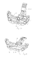
figures 2A, 2B illustrate, in a larger scale, two perspective views of the toe-piece offigure 1 , respective in the open and closed configuration; -
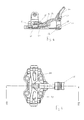
figure 3 is a view from above of the toe-piece offigure 2A ; -
figure 4 is a view of section IV-IV offigure 3 ; -
figure 5 is a plan view of the toe-piece offigure 2B ; -
figure 6 is the view of section VI-VI offigure 5 ; -
figure 7 is a perspective exploded view in larger scale of the toe-piece of the invention in a variant embodiment thereof; -
figures 8 and 9 illustrate two lateral views of the toe-piece offigure 7 , respectively in the closed and open configurations; -
figures 8A and 9A illustrate, in larger scale, respectively detail K offigure 8 and detail H offigure 9 . - With reference to the
figures, 1 denotes a plate destined to be blocked (using theholes 2 realised therein) to a ski, not illustrated. - The plate laterally forms opposite pairs of
prominences 4 which supportlongitudinal pins 4A with which the central parts of two right-angled jaws -
Relative pins upper sides 6A, 6B of the jaws. - The heads of the lower sides of the jaws are concavelyprofiled such as to define relative seatings S1, S2 that are symmetrical with respect to the longitudinal plane; the mutual distance between the surfaces delimiting the seatings decreases, proceeding from upstream towards downstream, i.e. in the sense of the arrow F (
figures 2A, 2B ). - The seatings are destined to receive, in a complementary coupling, lateral walls P1, P2 of a wedge-
shaped component 10. - Upstream (with respect to the arrow F) of the supports of the
prominences 4,theplate 1 exhibits a further pair of supports 8 which sustain a transversal pin 9 to which an intermediate point of a longitudinally-arrangedmain safety lever 11 is hinged; the internal end of the lever has afork 12 shape, which engages the wedge-shaped component 10. - The
fork 12 containselastic means 13; the internal abutment 12A of the fork constitutes an abutment for an end of the elastic means, the remaining end thereof interacts with thelarger base 10A of the wedge-shaped component 10. With the portion of the main safety lever situated on the opposite side, with reference to the pin 9, by means of a transversal pin14a safety lever 15 hinges in a scissor fashion to the interested portion of thefork 12. - In the illustrated example, a
spring 16 is associated to thepin 14, which spring tends to mutually open thelevers - The
safety lever 15 comprises an internal lower part 150 (i.e. facing towards the jaws) and an upper external part 151 (i.e. facing towards the end of the toe-piece). - The lower
internal part 150 of thesafety lever 15 bears atransversal pin 17 which idly supports awheel 18 provided such as to interact with the upper surface of the plate and, if required, with atooth 19 conformed thereby (seefigure 4 ). - The heads of the
jaws shaped element 10 identify a hinge, constituted by a female part and a male part. - The female part comprises the truncoconical path defined by the seatings S1, S2 fashioned in the heads of the jaws; the male part is constituted by the walls P1, P2 of the wedge-shaped component, the heads of the walls P1, P2 being orientated in a trunconical fashion.
- The
spring 13 stabilises the coupling of the male part with the female part; the wedge-shaped component can make axial sliding motions, opposed or facilitated by the spring. - In
figure 2B , the wedge-shaped component 10 is in the high position A (open configuration of the jaws). - With the passage of the
component 10 from the high position A to the low position B (figure 2A , closed configuration of the jaws), the distance between the heads of the jaws first reduces and then newly increases as soon as the aligning of the lower sides 5A, 5B of the jaws is passed through. - On reduction of the distance, and due to the stress exerted by female part on the male part, the
component 10 slides towards the spring in opposition to the elastic reaction (increased by the sliding) of the spring; once the alignment of the sides 5A, 5B has been passed, the component, 10, by action of thespring 13, slides in an opposite direction to the preceding direction. - These technical-functional aspects also occur with the passage of the wedge-
shaped component 10 from the low position B to the high position A. - Besides enabling the sliding movements (which are small), the
spring 13 stabilises in each operating situation, i.e. the open and closed configurations of the jaws and the passage between the configurations, the coupling between the female part and the male part of the hinge. - A variant is included which comprises the male part in the heads of the jaws (with the seatings S1, S2 curved externally) and, obviously, the female part of the
component 10, i.e. with the walls P1, P2 having seatings for the whole extension thereof and recessed in an inwards direction. - A possible alternative is obtained by realising the male part and the female part constituted by two sections, for example a section in which a wall P1 and the complementary seating S1 are obtained as in the accompanying figures, while the remaining part P2 and the seating S2 exhibit profiles according to the above-mentioned variant.
- In a further variant the walls P1, P2 are realised with a prismatic profile, and the seatings S1, S2 are complementary to the profiles; for example the profile of the walls P1, P2 are spire-shaped, with the vertex facing externally, or in a split polygonal shape.
- In a further variant (not illustrated) a spherical component is used, subject to a spring, the housing of which is defined by two seatings fashioned in the heads of the jaws; obviously this spherical component is inserted in the
fork 12 of themain lever 11. - The operating means mutually connecting the heads of the jaws and which are functionally associated to the
fork 12 of themain lever 11 are constituted by a wedge-shaped component 10 and by aspring 13; the only operations required consist in operations on the heads of the lower sides of the jaws such that they can be coupled with thecomponent 10. - With respect to the prior art, the solution provided enables considerably reducing the number of the elements, which translates into a simplification of the assembly thereof, in a reduction of costs and in a reduction of the overall weight of the toe-piece.
- In a further variant, illustrated in
figures 7 ,8, 9, 8A and 9A , thecomponent 10 comprises twolongitudinal projections 101 arranged at the relative upper surface (i.e. the surface of thecomponent 10 opposite theplate 1 when the toe-piece is in use). - The
longitudinal projections 101 are conformed such as to embrace the lateral edge of the wedge-shaped component 10 which is opposite the safety lever 15 (see in particularfigure 7 ). - The
internal part 150 of thesafety lever 15 comprises two portions, parallel to one another, which extend from theexternal part 151 of thesafety lever 15, and between which themain lever 11 is positioned and hinged (seefigure 7 ). - According to the variants, each portion of the
internal wall 150 comprises afirst appendage 152, which faces the wedge-shaped component 10, and asecond appendage 153. In detail, in the illustrated figures, theinternal part 150 of thesafety lever 15 forms an upturned C-shaped profile, and thefirst appendage 152 and thesecond appendage 153 are arranged at the ends of the C. - In particular, the
first appendage 152 of each portion is conformed such as to couple with a correspondinglongitudinal projection 101 arranged on the wedge-shaped component 10 when thesafety lever 15 is in the relative operating configuration (i.e. when the jaws are in the relative closed position, and the toe-piece is therefore in use). - Specifically, in the illustrated variant, each
longitudinal projection 101 exhibits a part having a curved profile (the part embracing the lateral edge of the wedge-shaped component 10), and eachfirst appendage 152 exhibits a part with a recess complementarily-shaped to the curved profile of thelongitudinal projection 101, such as to enable a reciprocal coupling (see in particularfigures 8A and 9A ). - Further in this variant the
plate 1 bears twowheels 100 arranged such that they are each abutted by asecond appendage 153 of thesafety lever 15. In particular, thewheels 100 are borne idle by corresponding pins 111 (transversal, in the case illustrated in the figures) fixed to theplate 1, provided with appropriate holes. In this way, with particular reference tofigures 8 and 9 , eachsecond appendage 153 abuts thecorresponding wheel 100 in each situation, i.e. both when the jaws are in the open configuration thereof and when they are in the relative closed position. - This variant advantageously significantly increases the stability of the toe-piece (and in particular the safety lever 15) when in use, i.e. when the jaws are in the relative closed position.
- The foregoing has been described by way of example; any constructional variants are understood to fall within the protective scope of the invention as claimed in the following claims.
Claims (15)
- A toe piece for an alpine ski bindings, comprising: a plate (1) destined to be blocked to a ski; two right-angled jaws (3A, 3B), central parts of which are hinged to the plate according to parallel longitudinal axes such as to be opposite the jaws, lower sides of which (5A, 5B) are facing towards an inside of the plate (1); two pins (7A, 7B), one per jaw, constrained to the internal surfaces of the upper sides (6A, 6B) of the jaws such as to be opposite and facing internally of the plate; operating means connecting the heads of the lower sides of the jaws such as to define therefor two extreme configurations, respectively open and closed; a main lever (11) of which an intermediate point is articulated to the plate according to a transversal axis (9), perpendicular to the articulation axes of the jaws with the plate, and end of the main lever, fork-shaped (13), functionally cooperating with the operating means; a safety lever (15) articulated, by means of a transversal pin (14), to the portion of the main lever situated, with respect to the transversal axis thereof, on an opposite side with respect to the fork, the safety lever being conformed such as to interact with the plate (1) at the closed configuration of the jaws; characterised in that the operating means comprise: a component (10) positioned internally of the fork and coupled with at least a housing defined by seatings fashioned in the heads of the lower sides of the jaws; elastic means interposed between the component and an abutment (12A) provided in the fork, destined to compress the component against the surfaces delimiting the seatings.
- The toe piece of claim 1, characterised in that the component is wedge-shaped, lateral walls (P1, P2) of which couple with the corresponding seatings (S1, S2) realised in the heads of the lower sides of the jaws.
- The toe piece of claim 2, characterised in that the component, at lateral walls thereof, has a truncoconical profile.
- The toe piece of claim 3, characterised in that the lateral walls (P1, P2) of the wedge-shaped component (10) are symmetrical with respect to the longitudinal plane of symmetry of the jaws.
- The toe piece of claim 3 or 4, characterised in that the lateral walls (P1, P2) of the wedge-shaped component (10) are curved in an external direction, and in that the corresponding seatings (S1, S2) fashioned in the heads are complementarily recessed with respect to the lateral walls.
- The toe piece of claim 3 or 4, characterised in that the lateral walls (P1, P2) of the wedge component (10) are recessed, and in that the corresponding seatings (S1, S2) fashioned in the heads are curved externally, complementarily to the lateral walls.
- The toe piece of any one of the preceding claims, characterised in that the transversal section of the wedge-shaped component (10) decreases proceeding from upstream towards downstream of the toe piece.
- The toe piece of claim 3 or 4, characterised in that the lateral walls (P1, P2) of the wedge component (10) exhibit prismatic profiles, and in that the seatings (S1, S2) are complementarily-shaped with respect to the profiles.
- The toe piece of claim 3 or 4, characterised in that the seatings (S1, S2) exhibit prismatic profiles, and in that the lateral walls (P1, P2) are conformed such as to couplingly receive the prismatic profiles.
- The toe piece of claim 1, characterised in that the component has a spherical profile.
- The toe piece of any one of the preceding claims, wherein the component (10) comprises a two longitudinal projections (101) arranged at the upper surface of the component (10); wherein the safety lever (15) comprises an internal part (150) and an external part (151); the internal part (150) comprising in turn two portions which extend from an external part (151) of the safety lever (15), and between which the main lever (11) is positioned; each portion of the internal part (150) comprising a first appendage (152), which faces the wedge-shaped component (10), conformed such as to couple with a corresponding longitudinal projection (101) when the jaws are in the relative closed position.
- The toe piece of the preceding claim, wherein each longitudinal projection (101) exhibits a part with a curved profile, and each first appendage (152) exhibits a part with a recess that is complementary to the curved profile of the longitudinal projection (101), in order to enable a reciprocal coupling thereof.
- The toe piece of claim 11 or 12, wherein each portion of the internal part (150) further comprises a second appendage (153); and wherein the plate (1) bears two wheels (100) arranged such as each to be abutted by a second appendage (153) of the safety lever (15) both when the jaws are in the open configuration thereof, and when the jaws are in the closed position thereof.
- The toe piece of the preceding claim, wherein the wheels (100) are borne idle by corresponding pins (111) fixed to the plate (1).
- The toe piece of claim 13 or 14, wherein the internal part (150) of the safety lever (15) forms an upturned C-shaped profile, and the first appendage (152) and the second appendage (153) are arranged at ends of the C-shaped profile.
Applications Claiming Priority (1)
| Application Number | Priority Date | Filing Date | Title |
|---|---|---|---|
| IT000243A ITBO20120243A1 (en) | 2012-05-04 | 2012-05-04 | TIP FOR SKI-MOUNTAINEER'S ATTACK |
Publications (2)
| Publication Number | Publication Date |
|---|---|
| EP2659940A1 true EP2659940A1 (en) | 2013-11-06 |
| EP2659940B1 EP2659940B1 (en) | 2014-12-10 |
Family
ID=46321223
Family Applications (1)
| Application Number | Title | Priority Date | Filing Date |
|---|---|---|---|
| EP13166182.9A Active EP2659940B1 (en) | 2012-05-04 | 2013-05-02 | Toe piece for a mountaineering ski binding |
Country Status (2)
| Country | Link |
|---|---|
| EP (1) | EP2659940B1 (en) |
| IT (1) | ITBO20120243A1 (en) |
Cited By (9)
| Publication number | Priority date | Publication date | Assignee | Title |
|---|---|---|---|---|
| EP2946817A1 (en) * | 2014-05-19 | 2015-11-25 | Ski Trab S.r.l. | Toe-piece for ski-touring bindings |
| EP3517188A3 (en) * | 2016-03-18 | 2019-10-30 | Fritz Barthel | Front unit for a slide board |
| IT201900000547A1 (en) | 2019-01-14 | 2020-07-14 | Atk Sports S R L | SKI ATTACHMENT TOE |
| IT201900013143A1 (en) | 2019-07-29 | 2021-01-29 | Atk Sports S R L | SKI ATTACHMENT TOE FOR SKI MOUNTAINEERING |
| IT201900025687A1 (en) | 2019-12-30 | 2021-06-30 | Atk Sports S R L | MOUNTAIN SKI ATTACHMENT TOE |
| EP3854465A1 (en) | 2020-01-24 | 2021-07-28 | The M Equipment | Front binding for a gliding device and gliding device provided with such a front binding |
| FR3106501A1 (en) * | 2020-01-24 | 2021-07-30 | The M Equipment | Front stop for sliding gear, and sliding gear equipped with such a front stop |
| IT202100018380A1 (en) | 2021-07-13 | 2023-01-13 | Atk Sports S R L | SKI BINDING TOE FOR SKI MOUNTAINEERING |
| EP4494722A1 (en) * | 2023-07-21 | 2025-01-22 | Salewa Sport AG | Front unit for a touring binding, comprising a wear-reducing element |
Citations (5)
| Publication number | Priority date | Publication date | Assignee | Title |
|---|---|---|---|---|
| EP0199098A2 (en) * | 1985-03-25 | 1986-10-29 | Fritz Dipl.-Ing. Barthel | Cross-country ski binding |
| ITMO20070365A1 (en) * | 2007-11-28 | 2009-05-29 | Atk Race Srl | AUTOMATIC LOCKING SYSTEM, PARTICULARLY SUITABLE FOR THE AUTOMATIC LOCKING OF THE TIP OF APLPINISM SKI ATTACKS |
| WO2009121187A1 (en) | 2008-04-03 | 2009-10-08 | G3 Genuine Guide Gear Inc. | Toe unit for alpine touring binding |
| EP2347807A1 (en) * | 2010-01-22 | 2011-07-27 | Atk Race S.R.L. | A toe piece for an alpine ski attachments |
| EP2392388A1 (en) | 2010-06-02 | 2011-12-07 | Salewa Sport AG | Touring binding |
-
2012
- 2012-05-04 IT IT000243A patent/ITBO20120243A1/en unknown
-
2013
- 2013-05-02 EP EP13166182.9A patent/EP2659940B1/en active Active
Patent Citations (5)
| Publication number | Priority date | Publication date | Assignee | Title |
|---|---|---|---|---|
| EP0199098A2 (en) * | 1985-03-25 | 1986-10-29 | Fritz Dipl.-Ing. Barthel | Cross-country ski binding |
| ITMO20070365A1 (en) * | 2007-11-28 | 2009-05-29 | Atk Race Srl | AUTOMATIC LOCKING SYSTEM, PARTICULARLY SUITABLE FOR THE AUTOMATIC LOCKING OF THE TIP OF APLPINISM SKI ATTACKS |
| WO2009121187A1 (en) | 2008-04-03 | 2009-10-08 | G3 Genuine Guide Gear Inc. | Toe unit for alpine touring binding |
| EP2347807A1 (en) * | 2010-01-22 | 2011-07-27 | Atk Race S.R.L. | A toe piece for an alpine ski attachments |
| EP2392388A1 (en) | 2010-06-02 | 2011-12-07 | Salewa Sport AG | Touring binding |
Cited By (16)
| Publication number | Priority date | Publication date | Assignee | Title |
|---|---|---|---|---|
| EP2946817A1 (en) * | 2014-05-19 | 2015-11-25 | Ski Trab S.r.l. | Toe-piece for ski-touring bindings |
| EP3517188A3 (en) * | 2016-03-18 | 2019-10-30 | Fritz Barthel | Front unit for a slide board |
| IT201900000547A1 (en) | 2019-01-14 | 2020-07-14 | Atk Sports S R L | SKI ATTACHMENT TOE |
| EP3689425A1 (en) | 2019-01-14 | 2020-08-05 | Atk Sports S.R.L. | A toe-piece of a ski binding |
| DE202020005614U1 (en) | 2019-07-29 | 2021-12-16 | Atk Sports S.R.L. | Toe piece of a ski binding for ski mountaineering |
| IT201900013143A1 (en) | 2019-07-29 | 2021-01-29 | Atk Sports S R L | SKI ATTACHMENT TOE FOR SKI MOUNTAINEERING |
| EP3782707A1 (en) | 2019-07-29 | 2021-02-24 | Atk Sports S.R.L. | A toe-piece of a ski binding for ski mountaineering |
| IT201900025687A1 (en) | 2019-12-30 | 2021-06-30 | Atk Sports S R L | MOUNTAIN SKI ATTACHMENT TOE |
| EP3845280A1 (en) | 2019-12-30 | 2021-07-07 | Atk Sports S.R.L. | A toe-piece of a ski mountaineering binding |
| EP3854465A1 (en) | 2020-01-24 | 2021-07-28 | The M Equipment | Front binding for a gliding device and gliding device provided with such a front binding |
| FR3106501A1 (en) * | 2020-01-24 | 2021-07-30 | The M Equipment | Front stop for sliding gear, and sliding gear equipped with such a front stop |
| IT202100018380A1 (en) | 2021-07-13 | 2023-01-13 | Atk Sports S R L | SKI BINDING TOE FOR SKI MOUNTAINEERING |
| EP4119205A1 (en) | 2021-07-13 | 2023-01-18 | Atk Sports S.R.L. | A toe-piece of a ski binding for ski mountaineering |
| US20230016853A1 (en) * | 2021-07-13 | 2023-01-19 | Atk Sports S.R.L. | Toe-piece of a ski binding for ski mountaineering |
| US11806605B2 (en) * | 2021-07-13 | 2023-11-07 | Atk Sports S.R.L. | Toe-piece of a ski binding for ski mountaineering |
| EP4494722A1 (en) * | 2023-07-21 | 2025-01-22 | Salewa Sport AG | Front unit for a touring binding, comprising a wear-reducing element |
Also Published As
| Publication number | Publication date |
|---|---|
| EP2659940B1 (en) | 2014-12-10 |
| ITBO20120243A1 (en) | 2013-11-05 |
Similar Documents
| Publication | Publication Date | Title |
|---|---|---|
| EP2659940B1 (en) | Toe piece for a mountaineering ski binding | |
| EP2748396B1 (en) | Quick coupling furniture hinge | |
| EP2737930B1 (en) | A device for removably blocking a central-front part of a ski boot to a platform of a ski for actuating the telemark technique | |
| AU2008207517B2 (en) | Eye gear having quick-release frame coupling blocks | |
| US8857823B2 (en) | Coupling means | |
| US8938864B2 (en) | Connector | |
| US20150157920A1 (en) | Four-part gliding apparatus | |
| WO2008099097A3 (en) | Aircraft wing including a plurality of dismountable members | |
| EP2553519A2 (en) | Flexible hinge for spectacles | |
| RU2526289C2 (en) | Flexor with clamp | |
| CN108552684A (en) | Watchband connection structure and wearing equipment thereof | |
| CN105377379B (en) | Foldable skis | |
| US20120195680A1 (en) | Connection device for assembling together two members | |
| CN201445021U (en) | Plug-in buckle head and plug-in buckle | |
| EP2815794B1 (en) | A toe-piece for an alpine ski binding | |
| US10514557B2 (en) | Frame for spectacles | |
| WO2012102579A3 (en) | Connection structure for thin-plate eyeglass frames and temples | |
| EP2900425A1 (en) | Replaceable jaw members for pliers | |
| CN203289796U (en) | Fixing structure of inner rail of server sliding rail and server case | |
| US9566499B2 (en) | Binding strap assist mechanism with a torsion spring | |
| US20190129201A1 (en) | Removable elastic hinge for eyeglass frames | |
| EP3689425B1 (en) | A toe-piece of a ski binding | |
| KR200445368Y1 (en) | Multi-Beauty Scissors | |
| CN206770337U (en) | A kind of quick detachment means and sucker | |
| KR200421656Y1 (en) | Scissors |
Legal Events
| Date | Code | Title | Description |
|---|---|---|---|
| PUAI | Public reference made under article 153(3) epc to a published international application that has entered the european phase |
Free format text: ORIGINAL CODE: 0009012 |
|
| AK | Designated contracting states |
Kind code of ref document: A1 Designated state(s): AL AT BE BG CH CY CZ DE DK EE ES FI FR GB GR HR HU IE IS IT LI LT LU LV MC MK MT NL NO PL PT RO RS SE SI SK SM TR |
|
| AX | Request for extension of the european patent |
Extension state: BA ME |
|
| 17P | Request for examination filed |
Effective date: 20140430 |
|
| RBV | Designated contracting states (corrected) |
Designated state(s): AL AT BE BG CH CY CZ DE DK EE ES FI FR GB GR HR HU IE IS IT LI LT LU LV MC MK MT NL NO PL PT RO RS SE SI SK SM TR |
|
| GRAP | Despatch of communication of intention to grant a patent |
Free format text: ORIGINAL CODE: EPIDOSNIGR1 |
|
| RIC1 | Information provided on ipc code assigned before grant |
Ipc: A63C 9/08 20120101AFI20140603BHEP Ipc: A63C 9/086 20120101ALI20140603BHEP |
|
| INTG | Intention to grant announced |
Effective date: 20140703 |
|
| GRAS | Grant fee paid |
Free format text: ORIGINAL CODE: EPIDOSNIGR3 |
|
| GRAA | (expected) grant |
Free format text: ORIGINAL CODE: 0009210 |
|
| AK | Designated contracting states |
Kind code of ref document: B1 Designated state(s): AL AT BE BG CH CY CZ DE DK EE ES FI FR GB GR HR HU IE IS IT LI LT LU LV MC MK MT NL NO PL PT RO RS SE SI SK SM TR |
|
| REG | Reference to a national code |
Ref country code: GB Ref legal event code: FG4D |
|
| REG | Reference to a national code |
Ref country code: CH Ref legal event code: EP |
|
| REG | Reference to a national code |
Ref country code: IE Ref legal event code: FG4D |
|
| REG | Reference to a national code |
Ref country code: AT Ref legal event code: REF Ref document number: 700350 Country of ref document: AT Kind code of ref document: T Effective date: 20150115 |
|
| REG | Reference to a national code |
Ref country code: DE Ref legal event code: R096 Ref document number: 602013000579 Country of ref document: DE Effective date: 20150129 |
|
| REG | Reference to a national code |
Ref country code: NL Ref legal event code: VDEP Effective date: 20141210 |
|
| REG | Reference to a national code |
Ref country code: NL Ref legal event code: VDEP Effective date: 20141210 |
|
| PG25 | Lapsed in a contracting state [announced via postgrant information from national office to epo] |
Ref country code: FI Free format text: LAPSE BECAUSE OF FAILURE TO SUBMIT A TRANSLATION OF THE DESCRIPTION OR TO PAY THE FEE WITHIN THE PRESCRIBED TIME-LIMIT Effective date: 20141210 Ref country code: LT Free format text: LAPSE BECAUSE OF FAILURE TO SUBMIT A TRANSLATION OF THE DESCRIPTION OR TO PAY THE FEE WITHIN THE PRESCRIBED TIME-LIMIT Effective date: 20141210 Ref country code: NO Free format text: LAPSE BECAUSE OF FAILURE TO SUBMIT A TRANSLATION OF THE DESCRIPTION OR TO PAY THE FEE WITHIN THE PRESCRIBED TIME-LIMIT Effective date: 20150310 Ref country code: ES Free format text: LAPSE BECAUSE OF FAILURE TO SUBMIT A TRANSLATION OF THE DESCRIPTION OR TO PAY THE FEE WITHIN THE PRESCRIBED TIME-LIMIT Effective date: 20141210 |
|
| REG | Reference to a national code |
Ref country code: LT Ref legal event code: MG4D |
|
| PG25 | Lapsed in a contracting state [announced via postgrant information from national office to epo] |
Ref country code: RS Free format text: LAPSE BECAUSE OF FAILURE TO SUBMIT A TRANSLATION OF THE DESCRIPTION OR TO PAY THE FEE WITHIN THE PRESCRIBED TIME-LIMIT Effective date: 20141210 Ref country code: HR Free format text: LAPSE BECAUSE OF FAILURE TO SUBMIT A TRANSLATION OF THE DESCRIPTION OR TO PAY THE FEE WITHIN THE PRESCRIBED TIME-LIMIT Effective date: 20141210 Ref country code: LV Free format text: LAPSE BECAUSE OF FAILURE TO SUBMIT A TRANSLATION OF THE DESCRIPTION OR TO PAY THE FEE WITHIN THE PRESCRIBED TIME-LIMIT Effective date: 20141210 Ref country code: GR Free format text: LAPSE BECAUSE OF FAILURE TO SUBMIT A TRANSLATION OF THE DESCRIPTION OR TO PAY THE FEE WITHIN THE PRESCRIBED TIME-LIMIT Effective date: 20150311 Ref country code: SE Free format text: LAPSE BECAUSE OF FAILURE TO SUBMIT A TRANSLATION OF THE DESCRIPTION OR TO PAY THE FEE WITHIN THE PRESCRIBED TIME-LIMIT Effective date: 20141210 |
|
| PG25 | Lapsed in a contracting state [announced via postgrant information from national office to epo] |
Ref country code: NL Free format text: LAPSE BECAUSE OF FAILURE TO SUBMIT A TRANSLATION OF THE DESCRIPTION OR TO PAY THE FEE WITHIN THE PRESCRIBED TIME-LIMIT Effective date: 20141210 |
|
| PG25 | Lapsed in a contracting state [announced via postgrant information from national office to epo] |
Ref country code: SK Free format text: LAPSE BECAUSE OF FAILURE TO SUBMIT A TRANSLATION OF THE DESCRIPTION OR TO PAY THE FEE WITHIN THE PRESCRIBED TIME-LIMIT Effective date: 20141210 Ref country code: CZ Free format text: LAPSE BECAUSE OF FAILURE TO SUBMIT A TRANSLATION OF THE DESCRIPTION OR TO PAY THE FEE WITHIN THE PRESCRIBED TIME-LIMIT Effective date: 20141210 Ref country code: EE Free format text: LAPSE BECAUSE OF FAILURE TO SUBMIT A TRANSLATION OF THE DESCRIPTION OR TO PAY THE FEE WITHIN THE PRESCRIBED TIME-LIMIT Effective date: 20141210 Ref country code: PT Free format text: LAPSE BECAUSE OF FAILURE TO SUBMIT A TRANSLATION OF THE DESCRIPTION OR TO PAY THE FEE WITHIN THE PRESCRIBED TIME-LIMIT Effective date: 20150410 Ref country code: RO Free format text: LAPSE BECAUSE OF FAILURE TO SUBMIT A TRANSLATION OF THE DESCRIPTION OR TO PAY THE FEE WITHIN THE PRESCRIBED TIME-LIMIT Effective date: 20141210 |
|
| PG25 | Lapsed in a contracting state [announced via postgrant information from national office to epo] |
Ref country code: PL Free format text: LAPSE BECAUSE OF FAILURE TO SUBMIT A TRANSLATION OF THE DESCRIPTION OR TO PAY THE FEE WITHIN THE PRESCRIBED TIME-LIMIT Effective date: 20141210 Ref country code: IS Free format text: LAPSE BECAUSE OF FAILURE TO SUBMIT A TRANSLATION OF THE DESCRIPTION OR TO PAY THE FEE WITHIN THE PRESCRIBED TIME-LIMIT Effective date: 20150410 |
|
| REG | Reference to a national code |
Ref country code: DE Ref legal event code: R097 Ref document number: 602013000579 Country of ref document: DE |
|
| PLBE | No opposition filed within time limit |
Free format text: ORIGINAL CODE: 0009261 |
|
| STAA | Information on the status of an ep patent application or granted ep patent |
Free format text: STATUS: NO OPPOSITION FILED WITHIN TIME LIMIT |
|
| PG25 | Lapsed in a contracting state [announced via postgrant information from national office to epo] |
Ref country code: DK Free format text: LAPSE BECAUSE OF FAILURE TO SUBMIT A TRANSLATION OF THE DESCRIPTION OR TO PAY THE FEE WITHIN THE PRESCRIBED TIME-LIMIT Effective date: 20141210 |
|
| 26N | No opposition filed |
Effective date: 20150911 |
|
| PG25 | Lapsed in a contracting state [announced via postgrant information from national office to epo] |
Ref country code: MC Free format text: LAPSE BECAUSE OF FAILURE TO SUBMIT A TRANSLATION OF THE DESCRIPTION OR TO PAY THE FEE WITHIN THE PRESCRIBED TIME-LIMIT Effective date: 20141210 Ref country code: LU Free format text: LAPSE BECAUSE OF FAILURE TO SUBMIT A TRANSLATION OF THE DESCRIPTION OR TO PAY THE FEE WITHIN THE PRESCRIBED TIME-LIMIT Effective date: 20150502 |
|
| REG | Reference to a national code |
Ref country code: AT Ref legal event code: UEP Ref document number: 700350 Country of ref document: AT Kind code of ref document: T Effective date: 20141210 |
|
| REG | Reference to a national code |
Ref country code: IE Ref legal event code: MM4A |
|
| PG25 | Lapsed in a contracting state [announced via postgrant information from national office to epo] |
Ref country code: SI Free format text: LAPSE BECAUSE OF FAILURE TO SUBMIT A TRANSLATION OF THE DESCRIPTION OR TO PAY THE FEE WITHIN THE PRESCRIBED TIME-LIMIT Effective date: 20141210 |
|
| PG25 | Lapsed in a contracting state [announced via postgrant information from national office to epo] |
Ref country code: IE Free format text: LAPSE BECAUSE OF NON-PAYMENT OF DUE FEES Effective date: 20150502 |
|
| REG | Reference to a national code |
Ref country code: FR Ref legal event code: PLFP Year of fee payment: 4 |
|
| PG25 | Lapsed in a contracting state [announced via postgrant information from national office to epo] |
Ref country code: BE Free format text: LAPSE BECAUSE OF FAILURE TO SUBMIT A TRANSLATION OF THE DESCRIPTION OR TO PAY THE FEE WITHIN THE PRESCRIBED TIME-LIMIT Effective date: 20141210 |
|
| PG25 | Lapsed in a contracting state [announced via postgrant information from national office to epo] |
Ref country code: MT Free format text: LAPSE BECAUSE OF FAILURE TO SUBMIT A TRANSLATION OF THE DESCRIPTION OR TO PAY THE FEE WITHIN THE PRESCRIBED TIME-LIMIT Effective date: 20141210 |
|
| REG | Reference to a national code |
Ref country code: FR Ref legal event code: PLFP Year of fee payment: 5 |
|
| PG25 | Lapsed in a contracting state [announced via postgrant information from national office to epo] |
Ref country code: HU Free format text: LAPSE BECAUSE OF FAILURE TO SUBMIT A TRANSLATION OF THE DESCRIPTION OR TO PAY THE FEE WITHIN THE PRESCRIBED TIME-LIMIT; INVALID AB INITIO Effective date: 20130502 Ref country code: BG Free format text: LAPSE BECAUSE OF FAILURE TO SUBMIT A TRANSLATION OF THE DESCRIPTION OR TO PAY THE FEE WITHIN THE PRESCRIBED TIME-LIMIT Effective date: 20141210 |
|
| PG25 | Lapsed in a contracting state [announced via postgrant information from national office to epo] |
Ref country code: CY Free format text: LAPSE BECAUSE OF FAILURE TO SUBMIT A TRANSLATION OF THE DESCRIPTION OR TO PAY THE FEE WITHIN THE PRESCRIBED TIME-LIMIT Effective date: 20141210 |
|
| PG25 | Lapsed in a contracting state [announced via postgrant information from national office to epo] |
Ref country code: TR Free format text: LAPSE BECAUSE OF FAILURE TO SUBMIT A TRANSLATION OF THE DESCRIPTION OR TO PAY THE FEE WITHIN THE PRESCRIBED TIME-LIMIT Effective date: 20141210 |
|
| GBPC | Gb: european patent ceased through non-payment of renewal fee |
Effective date: 20170502 |
|
| PG25 | Lapsed in a contracting state [announced via postgrant information from national office to epo] |
Ref country code: GB Free format text: LAPSE BECAUSE OF NON-PAYMENT OF DUE FEES Effective date: 20170502 |
|
| REG | Reference to a national code |
Ref country code: FR Ref legal event code: PLFP Year of fee payment: 6 |
|
| PG25 | Lapsed in a contracting state [announced via postgrant information from national office to epo] |
Ref country code: SM Free format text: LAPSE BECAUSE OF FAILURE TO SUBMIT A TRANSLATION OF THE DESCRIPTION OR TO PAY THE FEE WITHIN THE PRESCRIBED TIME-LIMIT Effective date: 20141210 |
|
| PG25 | Lapsed in a contracting state [announced via postgrant information from national office to epo] |
Ref country code: MK Free format text: LAPSE BECAUSE OF FAILURE TO SUBMIT A TRANSLATION OF THE DESCRIPTION OR TO PAY THE FEE WITHIN THE PRESCRIBED TIME-LIMIT Effective date: 20141210 |
|
| PG25 | Lapsed in a contracting state [announced via postgrant information from national office to epo] |
Ref country code: AL Free format text: LAPSE BECAUSE OF FAILURE TO SUBMIT A TRANSLATION OF THE DESCRIPTION OR TO PAY THE FEE WITHIN THE PRESCRIBED TIME-LIMIT Effective date: 20141210 |
|
| P01 | Opt-out of the competence of the unified patent court (upc) registered |
Effective date: 20230523 |
|
| PGFP | Annual fee paid to national office [announced via postgrant information from national office to epo] |
Ref country code: AT Payment date: 20230601 Year of fee payment: 11 |
|
| PGFP | Annual fee paid to national office [announced via postgrant information from national office to epo] |
Ref country code: DE Payment date: 20240610 Year of fee payment: 12 |
|
| REG | Reference to a national code |
Ref country code: AT Ref legal event code: MM01 Ref document number: 700350 Country of ref document: AT Kind code of ref document: T Effective date: 20240502 |
|
| PG25 | Lapsed in a contracting state [announced via postgrant information from national office to epo] |
Ref country code: AT Free format text: LAPSE BECAUSE OF NON-PAYMENT OF DUE FEES Effective date: 20240502 |
|
| PG25 | Lapsed in a contracting state [announced via postgrant information from national office to epo] |
Ref country code: AT Free format text: LAPSE BECAUSE OF NON-PAYMENT OF DUE FEES Effective date: 20240502 |
|
| PGFP | Annual fee paid to national office [announced via postgrant information from national office to epo] |
Ref country code: IT Payment date: 20250528 Year of fee payment: 13 |
|
| PGFP | Annual fee paid to national office [announced via postgrant information from national office to epo] |
Ref country code: FR Payment date: 20250520 Year of fee payment: 13 |
|
| PGFP | Annual fee paid to national office [announced via postgrant information from national office to epo] |
Ref country code: CH Payment date: 20250601 Year of fee payment: 13 |
|
| REG | Reference to a national code |
Ref country code: DE Ref legal event code: R119 Ref document number: 602013000579 Country of ref document: DE |
|
| PG25 | Lapsed in a contracting state [announced via postgrant information from national office to epo] |
Ref country code: DE Free format text: LAPSE BECAUSE OF NON-PAYMENT OF DUE FEES Effective date: 20251202 |