EP2664937A2 - Halbleitervorrichtung und Spannungsmessvorrichtung - Google Patents
Halbleitervorrichtung und Spannungsmessvorrichtung Download PDFInfo
- Publication number
- EP2664937A2 EP2664937A2 EP13165502.9A EP13165502A EP2664937A2 EP 2664937 A2 EP2664937 A2 EP 2664937A2 EP 13165502 A EP13165502 A EP 13165502A EP 2664937 A2 EP2664937 A2 EP 2664937A2
- Authority
- EP
- European Patent Office
- Prior art keywords
- control unit
- voltage
- signal
- common bus
- voltage measuring
- Prior art date
- Legal status (The legal status is an assumption and is not a legal conclusion. Google has not performed a legal analysis and makes no representation as to the accuracy of the status listed.)
- Withdrawn
Links
Images


Classifications
-
- G—PHYSICS
- G01—MEASURING; TESTING
- G01R—MEASURING ELECTRIC VARIABLES; MEASURING MAGNETIC VARIABLES
- G01R31/00—Arrangements for testing electric properties; Arrangements for locating electric faults; Arrangements for electrical testing characterised by what is being tested not provided for elsewhere
- G01R31/36—Arrangements for testing, measuring or monitoring the electrical condition of accumulators or electric batteries, e.g. capacity or state of charge [SoC]
- G01R31/382—Arrangements for monitoring battery or accumulator variables, e.g. SoC
- G01R31/3835—Arrangements for monitoring battery or accumulator variables, e.g. SoC involving only voltage measurements
-
- B—PERFORMING OPERATIONS; TRANSPORTING
- B60—VEHICLES IN GENERAL
- B60L—PROPULSION OF ELECTRICALLY-PROPELLED VEHICLES; SUPPLYING ELECTRIC POWER FOR AUXILIARY EQUIPMENT OF ELECTRICALLY-PROPELLED VEHICLES; ELECTRODYNAMIC BRAKE SYSTEMS FOR VEHICLES IN GENERAL; MAGNETIC SUSPENSION OR LEVITATION FOR VEHICLES; MONITORING OPERATING VARIABLES OF ELECTRICALLY-PROPELLED VEHICLES; ELECTRIC SAFETY DEVICES FOR ELECTRICALLY-PROPELLED VEHICLES
- B60L50/00—Electric propulsion with power supplied within the vehicle
- B60L50/50—Electric propulsion with power supplied within the vehicle using propulsion power supplied by batteries or fuel cells
-
- G—PHYSICS
- G01—MEASURING; TESTING
- G01R—MEASURING ELECTRIC VARIABLES; MEASURING MAGNETIC VARIABLES
- G01R19/00—Arrangements for measuring currents or voltages or for indicating presence or sign thereof
- G01R19/18—Arrangements for measuring currents or voltages or for indicating presence or sign thereof using conversion of DC into AC, e.g. with choppers
-
- G—PHYSICS
- G01—MEASURING; TESTING
- G01R—MEASURING ELECTRIC VARIABLES; MEASURING MAGNETIC VARIABLES
- G01R31/00—Arrangements for testing electric properties; Arrangements for locating electric faults; Arrangements for electrical testing characterised by what is being tested not provided for elsewhere
- G01R31/36—Arrangements for testing, measuring or monitoring the electrical condition of accumulators or electric batteries, e.g. capacity or state of charge [SoC]
- G01R31/364—Battery terminal connectors with integrated measuring arrangements
-
- G—PHYSICS
- G01—MEASURING; TESTING
- G01R—MEASURING ELECTRIC VARIABLES; MEASURING MAGNETIC VARIABLES
- G01R31/00—Arrangements for testing electric properties; Arrangements for locating electric faults; Arrangements for electrical testing characterised by what is being tested not provided for elsewhere
- G01R31/36—Arrangements for testing, measuring or monitoring the electrical condition of accumulators or electric batteries, e.g. capacity or state of charge [SoC]
- G01R31/371—Arrangements for testing, measuring or monitoring the electrical condition of accumulators or electric batteries, e.g. capacity or state of charge [SoC] with remote indication, e.g. on external chargers
-
- G—PHYSICS
- G01—MEASURING; TESTING
- G01R—MEASURING ELECTRIC VARIABLES; MEASURING MAGNETIC VARIABLES
- G01R31/00—Arrangements for testing electric properties; Arrangements for locating electric faults; Arrangements for electrical testing characterised by what is being tested not provided for elsewhere
- G01R31/36—Arrangements for testing, measuring or monitoring the electrical condition of accumulators or electric batteries, e.g. capacity or state of charge [SoC]
- G01R31/396—Acquisition or processing of data for testing or for monitoring individual cells or groups of cells within a battery
-
- H—ELECTRICITY
- H01—ELECTRIC ELEMENTS
- H01M—PROCESSES OR MEANS, e.g. BATTERIES, FOR THE DIRECT CONVERSION OF CHEMICAL ENERGY INTO ELECTRICAL ENERGY
- H01M10/00—Secondary cells; Manufacture thereof
- H01M10/42—Methods or arrangements for servicing or maintenance of secondary cells or secondary half-cells
- H01M10/48—Accumulators combined with arrangements for measuring, testing or indicating the condition of cells, e.g. the level or density of the electrolyte
-
- G—PHYSICS
- G01—MEASURING; TESTING
- G01R—MEASURING ELECTRIC VARIABLES; MEASURING MAGNETIC VARIABLES
- G01R15/00—Details of measuring arrangements of the types provided for in groups G01R17/00 - G01R29/00, G01R33/00 - G01R33/26 or G01R35/00
- G01R15/14—Adaptations providing voltage or current isolation, e.g. for high-voltage or high-current networks
- G01R15/18—Adaptations providing voltage or current isolation, e.g. for high-voltage or high-current networks using inductive devices, e.g. transformers
-
- Y—GENERAL TAGGING OF NEW TECHNOLOGICAL DEVELOPMENTS; GENERAL TAGGING OF CROSS-SECTIONAL TECHNOLOGIES SPANNING OVER SEVERAL SECTIONS OF THE IPC; TECHNICAL SUBJECTS COVERED BY FORMER USPC CROSS-REFERENCE ART COLLECTIONS [XRACs] AND DIGESTS
- Y02—TECHNOLOGIES OR APPLICATIONS FOR MITIGATION OR ADAPTATION AGAINST CLIMATE CHANGE
- Y02E—REDUCTION OF GREENHOUSE GAS [GHG] EMISSIONS, RELATED TO ENERGY GENERATION, TRANSMISSION OR DISTRIBUTION
- Y02E60/00—Enabling technologies; Technologies with a potential or indirect contribution to GHG emissions mitigation
- Y02E60/10—Energy storage using batteries
Definitions
- the present invention relates to a device for measuring the voltage generated by each of plural series-coupled voltage sources and collecting a measurement result and is suitably applicable, particularly, to a semiconductor device making up such a device.
- a person touches an assembled battery having a high voltage he or she may be seriously injured by electrification. It is, therefore, necessary to electrically insulate parts such as an assembled battery for electric vehicle, the motor coupled with the assembled battery via a conductive wire, and the inverter circuit to drive the motor from a vehicle's low-voltage electrical system which includes parts operating in a state of being coupled to the vehicle body used as a common reference potential.
- the plural voltage measuring units included in a voltage measuring device to measure the voltages of the plural cells respectively, those to measure the voltages of cells on the high potential side of the assembled battery are several hundred volts higher in potential than the low-potential electrical system.
- the control signals to be sent from the system control device to the voltage measuring device and the signals representing battery voltage data collected by the voltage measuring device and to be transmitted from the voltage measuring device to the system control device are required to be electrically insulated.
- a system control device and plural voltage measuring units are coupled, on a one-to-one basis, via communication paths each provided with an insulating element such as a photocoupler for electric insulation.
- an assembled battery system which includes plural cells series-coupled in multiple stages.
- plural battery modules each measure the voltages of plural cells individually and are each coupled through a bus and via an insulating element to a microcomputer for system control.
- Each of the battery modules is provided with a voltage detector for measuring the voltages of plural cells individually and a microcomputer coupled to the voltage detector.
- the voltages of cells individually measured by each battery module are transmitted to the microcomputer for system control through a bus and via an insulating element.
- the microcomputer for system control is provided with as many communication ports as the number of battery modules to be coupled thereto.
- the battery modules are coupled to the communication ports on a one-to-one basis through the buses (so referred to in the patent document).
- the battery modules measure the voltages of the plural cells series-coupled in multiple stages, so that they mutually differ in potential. Battery modules on the high potential side reach several hundred volts in potential.
- the microcomputer for system control on the other hand is disposed on the low voltage side with a potential close to that of the vehicle body.
- the buses are each electrically insulated using an insulating element such as a photocoupler.
- a battery system in which, instead of coupling all battery modules and a microcomputer for system control on a one-to-one basis through buses each insulated using an insulating element, only some battery modules are coupled to the microcomputer for system control on a one-to-one basis with the other battery modules respectively coupled to adjacent ones without being insulated.
- the battery modules coupled to adjacent ones mutually differ in potential, but the potential difference between any two adjacent battery modules is not large, so that information represented by electric current is transmitted between them involving no insulating element. In this way, the number of communication paths insulated using insulating elements can be reduced for cost reduction.
- an assembled battery system which includes plural cells series-coupled in multiple stages.
- plural intelligent detection modules each being for measuring the voltages of plural cells individually are each serially coupled, on a one-to-one basis, via an insulating element to a multiplexer coupled to a central microcomputer.
- the system is controlled in a decentralized manner by the intelligent detection modules and the central microcomputer.
- the intelligent detection modules are coupled to the cells series-coupled in multiple stages with the intelligent detection modules corresponding to the multiple stages, causing the intelligent detection modules to mutually differ in potential.
- the intelligent detection modules are coupled to the central microcomputer via the multiplexer, they communicate with the central microcomputer basically on a one-to-one basis.
- the assembled batteries disclosed in the above related-art patent documents are each comprised of cells series-coupled in multiple stages and, in each of the assembled batteries, plural battery voltage measuring units each being for measuring the voltages of individual cells are coupled to a microcomputer for system control on a one-to-one basis.
- a microcomputer for system control When the number of stages of series-coupled cells is increased to have a higher voltage generated by the assembled battery, it is necessary to proportionally increase the number communication paths for coupling between plural battery voltage measuring units and a microcomputer for system control.
- Increasing the number of communication paths requires the number of communication ports of the microcomputer for system control to be increased by the same number while the volume of wire harness to make up communication paths also increases. This inevitably increases the system cost.
- An embodiment of the present invention is as follows.
- each of the voltage measuring units is comprised of an analog front end unit for measuring the voltages of individual cells, an interface unit for interfacing between the voltage measuring unit and the common bus, a voltage measurement control unit for controlling the analog front end unit and the interface unit, and an insulating element for allowing communication between the voltage measurement control unit and the interface unit in an electrically insulated state.
- the interface unit of each of the plural voltage measuring units is electrically insulated, so that it can be coupled to a low-voltage power supply system of the electrical system that includes the battery system control unit. Since there is no potential difference between the interface unit and the battery system control unit, they can be coupled to each other via a common bus. With the plural voltage measuring units and the battery system control unit coupled via the common bus, the battery system control unit requires no communication port other than that for interfacing with the common bus and, also, no communication wire harness is required other than the common bus. This keeps the system cost low.
- a semiconductor device is for measuring a voltage of each of plural cells (B11 to Bmn) which are series-coupled in multiple stages making up an assembled battery and for transmitting a measurement result to a battery system control unit (1) via a common bus (9).
- the semiconductor device includes an analog front end unit (4) which measures the voltage of each of the cells and a voltage measurement control unit (5) which performs control to transmit a measurement result outputted from the analog front end unit to the common bus.
- the semiconductor device further includes an interface unit (6) which can make switching between driving the common bus and setting a coupling thereof with the common bus to high impedance and an insulating element (8) which allows communication between the voltage measurement control unit and the interface unit in a state of being electrically insulated from each other.
- the battery system control unit (1) requires no communication port other than that for interfacing with the common bus (9) and, also, no communication wire harness is required other than the common bus (9). This keeps the system cost low. Since the analog front end unit (4) and the voltage measurement control unit (5) are both disposed on the battery side with respect to the insulator circuit (8) (may hereinafter be referred to simply as the "battery side") and are included in a same power supply system, the power consumption can be reduced by various methods.
- the semiconductor device described in [1] above further includes a regulator (7) which stabilizes power supplied from the cells and supplies the power to the voltage measurement control unit.
- the regulator has a power supply control signal (10) for supplying and stopping the power to the voltage measurement control unit.
- voltage measurement can be performed without being affected by noise, for example, variations in the load on the battery.
- power supply to the analog front end unit (4), voltage measurement control unit (5) and insulator circuit (8) can be controlled either individually or collectively. This makes it possible to reduce the power consumption of the voltage measurement control unit (2).
- the power supply control signal is controlled based on a receive signal (30) outputted from the interface unit.
- the semiconductor device described in [3] above further includes a power restoration control circuit (41), an inductively coupled insulating element (46) and a peak detection circuit (47).
- the power restoration control circuit starts outputting a first AC signal based on the receive signal.
- the inductively coupled insulating element converts the first AC signal in a state of being insulated DC-wise into a second AC signal and transmits the second AC signal to the peak detection circuit.
- the peak detection circuit controls the power supply control signal using the second AC signal after rectifying and smoothing the second AC signal.
- the power supply to the battery side that has been shut off can be restored using a control command transmitted via the common bus (9).
- the semiconductor device described in [1] above further includes a power supply terminal (VCC) on a low voltage side for supplying power to the interface unit.
- the interface unit has a differential drive circuit (including 23 and 25 to 28) and a differential reception circuit (24).
- the differential drive circuit operates using power supplied from the power supply terminal on the low voltage side and either drives the common bus using a differential signal or outputs high impedance.
- the differential reception circuit operates using the power supplied from the power supply terminal on the low voltage side and receives the differential signal from the common bus.
- the differential drive circuit drives the common bus in a manner to meet a CAN standard, and the differential reception circuit receives a signal from the common bus meeting the CAN standard.
- the analog front end unit, the voltage measurement control unit, the interface unit, and the insulating element are integrated in a same package.
- the semiconductor device described in [7] above makes it possible to reduce the system cost by making components smaller and also to reduce the area required for mounting the substrate.
- the insulating element is a transformer formed over a semiconductor substrate with a primary side and a secondary side of the transformer insulated from each other across an insulating layer and with the voltage measurement control unit also formed over the semiconductor substrate.
- the semiconductor device described in [8] above makes it possible to reduce the system cost by making components smaller and also to reduce the area required for mounting the substrate.
- the insulating element is a transformer formed over a semiconductor substrate with a primary side and a secondary side of the transformer insulated from each other across an insulating layer. Also, the voltage measurement control unit, the insulating element, and the interface unit are formed over a same SOI substrate, the voltage measurement control unit and the interface unit being formed over wells insulated from each other.
- the semiconductor device described in [9] above makes it possible to reduce the system cost by making components smaller and also to reduce the area required for mounting the substrate.
- a voltage measuring device includes plural voltage measuring units (2_1 to 2_m) corresponding to plural cell groups (B11 to B1n, B21 to B2n, - - - Bm1 to Bmn) making up an assembled battery by being series-coupled in multiple stages, a common bus (9) intercoupling the voltage measuring units, and a battery system control unit (1) coupled to the common bus.
- the voltage measuring units each include an analog front end unit (4) which measures the voltage of each cell included in a corresponding one of the cell groups and a voltage measurement control unit (5) which performs control to transmit a measurement result outputted from the analog front end unit to the common bus.
- the voltage measuring units each further include an interface unit (6) which can make switching between driving the common bus and setting a coupling thereof with the common bus to high impedance and an insulating element (8) which allows communication between the voltage measurement control unit and the interface unit in a state of being electrically insulated from each other.
- the battery system control unit (1) transmits control commands to plural voltage measuring units (2_1 to 2_m) via the common bus (9).
- Each of the voltage measuring units (2_1 to 2_m) controls the corresponding analog front end unit (4) based on the control command received, measures the voltages of plural cells of the corresponding battery group, and transmits the measurements to the battery system control unit (1) via the common bus.
- the voltage measuring units each further include a regulator (7) which stabilizes power supplied from a corresponding one of the cell groups and supplies the power to the voltage measurement control unit.
- the regulator supplies and stops the power to the voltage measurement control unit according to a power supply control signal (10).
- voltage measurement can be performed without being affected by noise, for example, variations in the load on the battery.
- power supply to the analog front end unit (4), voltage measurement control unit (5) and insulator circuit (8) can be controlled either individually or collectively. This makes it possible to reduce the power consumption of the voltage measurement control unit (2).
- the voltage measuring units each control the power supply control signal according to a control command issued by the battery system control unit via the common bus.
- the voltage measurement control unit can output, based on the control command, a signal for stopping power supply to the voltage measurement control unit as the power supply control signal.
- the voltage measuring units each further include a power restoration control circuit (41), an inductively coupled insulating element (46), and a peak detection circuit (47).
- the power restoration control circuit starts outputting a first AC signal based on the control command.
- the inductively coupled insulating element converts the first AC signal in a state of being insulated DC-wise into a second AC signal and transmits the second AC signal to the peak detection circuit.
- the peak detection circuit is capable of outputting a signal generated by rectifying and smoothing the second AC signal as the power supply control signal for causing power supply to the voltage measurement control unit to be started.
- the power supply to the battery side that has been shut off can be restored using a control command transmitted via the common bus (9).
- the voltage measuring units each further include a regulator (7) which stabilizes power supplied from a corresponding one of the cell groups and supplies the power to the voltage measurement control unit.
- the interface unit is supplied with constant-voltage power with which the battery system control unit is also supplied.
- the interface unit has a differential drive circuit (including 23 and 25 to 28) and a differential reception circuit (24).
- the differential drive circuit operates using power supplied on the low voltage side and either drives the common bus using a differential signal or outputs high impedance.
- the differential reception circuit operates using power supplied on the low voltage side and receives a differential signal from the common bus.
- the network including the common bus meets a CAN standard.
- a voltage measuring device includes plural voltage measuring units (2_1 to 2_m) corresponding to plural cell groups (B11 to B1n, B21 to B2n, - - - Bm1 to Bmn) making up an assembled battery by being series-coupled in multiple stages and a battery system control unit (1) coupled to the voltage measuring units via a transmission path (9).
- the voltage measuring units each include an analog front end unit (4) which measures the voltage of each cell included in a corresponding one of the cell groups, an interface unit (6) which transmits a measurement result outputted from the analog front end unit to the transmission path, and a voltage measurement control unit (5) which controls the analog front end unit and the interface unit.
- the voltage measuring units each further include an insulating element (8) which allows communication between the voltage measurement control unit and the interface unit in a state of being electrically insulated from each other and a regulator (7) which stabilizes power supplied from a corresponding one of the cell groups and supplies the power to the voltage measurement control unit.
- the regulator has a control function for stopping and starting power supply to the voltage measurement control unit based on a control command issued from the battery system control unit via the transmission path.
- supplying and shutting off of power to the voltage measuring units (2_1 to 2_m) can also be controlled using control commands transmitted by the battery system control unit (1) via a transmission path other than the common bus. This makes it possible to reduce the power consumption of the battery system control unit (1).
- the voltage measurement control unit causes power supply thereto to be stopped based on the control command.
- the voltage measuring units each further include a power restoration control circuit (41), an inductively coupled insulating element (46), and a peak detection circuit (47).
- the power restoration control circuit starts outputting a first AC signal based on the control command.
- the inductively coupled insulating element converts the first AC signal in a state of being insulated DC-wise into a second AC signal and transmits the second AC signal to the peak detection circuit.
- the peak detection circuit causes power supply to the voltage measurement control unit to be started using a signal generated by rectifying and smoothing the second AC signal.
- FIG. 3 is a block diagram of an assembled-battery voltage measuring device according to an embodiment of means for solving problems.
- an assembled battery is comprised of plural series-coupled cells B11 to Bmn, and the voltage of each of the cells B11 to Bmn of the assembled battery is measured for monitoring and control by a battery system control unit 1.
- the assembled battery includes as many as m cell groups with each cell group having as many as n series-coupled cells.
- the m cell groups are provided with voltage measuring units 2_1 to 2_m.
- the voltage measuring units 2_1 to 2_m are respectively coupled to the battery system control unit 1 not on a one-to-one basis but collectively via a common bus 9.
- Each of the voltage measuring units 2_1 to 2_m includes a multiplexer 3, an analog front end 4, a voltage measurement control unit 5, an interface unit 6, a regulator 7, and an insulator circuit 8.
- the multiplexer 3 selects a cell to be measured out of the n cells and couples the selected cell to the analog front end unit 4.
- the analog front end unit 4 includes an analog/digital converter. Under control by the voltage measurement control unit 5, the analog front end unit 4 measures the voltage of the cell selected by the multiplexer 3 and outputs the voltage measurement after conversion into a digital value.
- the voltage measurement control unit 5 is, for example, a microcomputer (or a microcontroller) and, in communicating with the battery system control unit 1, controls communication based on the protocol of the common bus 9.
- the voltage measurement control unit 5 interprets the control command and, by controlling the multiplexer 3 and the analog front end unit 4, collects battery voltage measurement.
- the voltage measurement control unit 5 transmits the collected measurement to the battery system control unit 1.
- the insulator circuit 8 includes an insulating element, a drive circuit to drive the insulating element, and a detection circuit.
- the insulating element may be, for example, a photocoupler, an inductively coupled insulating element, or a capacitively coupled insulating element.
- the interface unit 6 is a bus transceiver which meets the physical and electrical standards for the common bus 9.
- the battery system control unit 1 and each of the voltage measuring units 2_1 to 2_m are coupled on a one-to-one basis via a communication path provided with an insulating element to enable communication in an electrically insulated state.
- a problem is posed as to where to insert the insulating element.
- the common bus requires a state in which high impedance is outputted without the common bus being driven.
- there are physical and electrical standards to be met by the common bus Therefore, simply inserting an insulating element in the coupling part between the interface unit 6 and the common bus 9 cannot meet the physical and electrical standards for the common bus 9.
- the insulator circuit 8 is inserted between the analog front end unit 4 and the voltage measurement control unit 5.
- the battery system control unit 1 With the plural voltage measuring units 2 and the battery system control unit 1 coupled via the common bus 9, the battery system control unit 1 requires no communication port other than that for interfacing with the common bus 9 and, also, no communication wire harness is required other than the common bus 9. This keeps the system cost low.
- an analog/digital converter provides a multiple bit parallel output, so that at least as many insulating elements as the number of bits of the analog/digital converter are required.
- a larger number of insulating elements are required.
- the voltage measurement control unit 5 also requires to be supplied with VCC, a low-voltage power supply for electrical system with which the battery system control unit 1 is also supplied.
- VCC a low-voltage power supply for electrical system with which the battery system control unit 1 is also supplied.
- an assembled battery made up of cells series-coupled in multiple stages outputs a high voltage of up to several hundred volts.
- the voltage measuring unit 2_1 is coupled to the highest-potential cell group B11 to B1n, so that the ground level of the analog front end unit 4 is of a high potential.
- the cell group B11 to B1n comprised of as many as n series-coupled cells outputs several tens of volts.
- the voltage measuring units 2_1 to 2_m are each provided with a regulator 7 which generates power supply VDD by stepping down several tens of volts and supplies VDD to the analog front end unit 4.
- VDD is supplied to the analog front end unit 4 and the voltage measurement control unit 5.
- a circuit for example, a microcomputer which corresponds to the above voltage measurement control unit 5 communicates with a cell voltage measuring circuit and controls cell voltage measurement.
- This circuit corresponding to the above voltage measurement control unit 5 has power used to perform operation supplied from the cells that are its target of voltage measurement.
- the power supply circuit 2 generates power supply VDD by stabilizing the power supplied from plural cells making up a part of the assembled battery.
- the power supplied from plural cells making up a part of the assembled battery is directly supplied as VCC without using any power supply circuit.
- no circuit is denoted as a power supply circuit, the power needed by the circuit on the battery side that is insulated using insulating elements is apparently provided by the battery.
- power supply VDD is supplied from the battery side to the voltage measurement control unit 5. It may appear that changing this configuration so as to supply power VCC for electrical system from the battery system control system 1 side to the voltage measurement control unit 5 does not cause any problem.
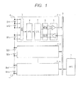
- FIG. 1 is a block diagram of an assembled-battery voltage measuring device according to a first embodiment of the present invention.
- an assembled battery is comprised of plural series-coupled cells B11 to Bmn, and the voltage of each of the cells B11 to Bmn of the assembled battery is measured for monitoring and control by a battery system control unit 1.
- the assembled battery includes as many as m cell groups with each cell group having as many as n series-coupled cells.
- the m cell groups are provided with voltage measuring units 2_1 to 2_m.
- the voltage measuring units 2_1 to 2_m are respectively coupled to the battery system control unit 1 not on a one-to-one basis but collectively via a common bus 9.
- Each of the voltage measuring units 2_1 to 2_m (hereinafter may also be referred to collectively as “voltage measuring units 2" or individually as a “voltage measuring unit 2”) includes a multiplexer 3, an analog front end 4, a voltage measurement control unit 5, an interface unit 6, and an insulator circuit 8.
- the multiplexer 3 selects a cell to be measured out of the n cells and couples the selected cell to the analog front end unit 4.
- the analog front end unit 4 includes an analog/digital converter. Under control by the voltage measurement control unit 5, the analog front end unit 4 measures the voltage of the cell selected by the multiplexer 3 and outputs the voltage measurement after conversion into a digital value.
- the voltage measurement control unit 5 is, for example, a microcomputer and, based on the protocol of the common bus 9, controls communication with the battery system control unit 1. In performing communication control, the voltage measurement control unit 5 interprets a control command received from the battery system control unit 1, collects cell voltage measurement by controlling the multiplexer 3 and the analog front end unit 4, and transmits the collected voltage measurement to the battery system control unit 1.
- the insulator circuit 8 includes an insulating element, a drive circuit to drive the insulating element, and a detection circuit.
- the insulating element may be, for example, a photocoupler, an inductively coupled insulating element, or a capacitively coupled insulating element.
- the interface unit 6 is a bus transceiver which meets the physical and electrical standards for the common bus 9.
- the battery system control unit 1 and each of the voltage measuring units 2_1 to 2_m are coupled on a one-to-one basis via a communication path provided with an insulating element to enable communication in an electrically insulated state.
- the insulator circuit 8 is inserted between the interface unit 6 and the voltage measurement control unit 5. This allows the interface unit 6 to be used as a bus transceiver meeting the physical and electrical standards for the common bus 9.
- the battery system control unit 1 With the plural voltage measuring units 2 and the battery system control unit 1 coupled via the common bus 9, the battery system control unit 1 requires no communication port other than that for interfacing with the common bus 9 and, also, no communication wire harness is required other than the common bus 9. This keeps the system cost low.
- FIG. 8 is a block diagram showing an application of a voltage measuring device.
- a motor 60 and a motor driving inverter 61 are coupled to an assembled battery which supplies power to them.
- the voltage of each of the cells B11 to Bmn of the assembled battery is measured for monitoring by a battery system control unit 1.
- Voltage measuring units 2_1 to 2_m which measure the voltages of the grouped cells B11 to B1n, B21 to B2n, - - - Bm1 to Bmn are disposed near the grouped cells.
- the grouped cells B11 to B1n, B21 to B2n, - - -, Bm1 to Bmn are widely disposed, for example, under seats.
- the cell groups are coupled to the battery system control unit 1 on a one-to-one basis, wiring totaling up to several meters in length may be required.
- Using a common bus in such a case makes it possible to traversely wire all the grouped cells B11 to B1n, B21 to B2n, - - -, Bm1 to Bmn so as to form a continuous wiring path. This can reduce the total length of wiring to one half or shorter.
- both the analog front end unit 4 and the voltage measurement control unit 5 are, as shown in FIG. 1 , disposed in a same power supply system to be on the cell side as seen from the insulator circuit 8. This makes it possible to reduce power consumption in various ways.
- the power consumption of the assembled battery can be reduced, for example, by adopting some or all of the following methods.
- FIG. 2 is a block diagram of an assembled-battery voltage measuring device according to a second embodiment of the present invention.
- an assembled battery is comprised of plural series-coupled cells B11 to Bmn, and the voltage of each of the cells B11 to Bmn is measured for monitoring and control by a battery system control unit 1.
- the assembled-battery voltage measuring device of the second embodiment differs from the assembled-battery voltage measuring device of the first embodiment in that the voltage measuring unit 2_1 is provided with a regulator 7.
- the regulator 7 steps down the voltage of tens of volts generated by the group of n series-coupled cells B1a to B1n and supplies the stepped-down voltage as power supply VDD to the analog front end unit 4 and the voltage measurement control unit 5.
- the other voltage measuring units 2_2 to 2_m are also configured identically to the voltage measuring unit 2_1.
- the number of cells (battery cells) series-coupled in an assembled battery is dependent on, for example, output voltage specification, so that the number of series-coupled cells is not necessarily divisible by the number of voltage measuring units 2. Namely, the voltage generated by the cells series-coupled in a cell group may differ between voltage measuring units. Also, the voltage largely varies with load and, when the load is inductive like a motor, the load may largely vary with a counter-electromotive force. Other noises may also cause the potential to vary between points along series-coupled cells.
- the regulator 7 stabilizes the voltage generated by the cells series-coupled in each cell group, generates the power supply VDD and supplies it to the analog front end unit 4 and the voltage measurement control unit 5. This makes it possible to measure cell voltages without being affected by noises such as battery load variations.
- a power supply control signal 10 to the regulator 10 and control power supply to the analog front end unit 4, voltage measurement control unit 5 and insulator circuit 8 either individually or collectively.
- careful power supply control allows power consumption to be effectively reduced, for example, by stopping power supply to the voltage measurement control unit 5 and the insulator circuit 8 while the analog front end unit 4 is engaged in cell voltage measurement or by stopping power supply to the analog front end unit 5 while communication is being performed.
- stopping the power supply stabilization operation of the regulator 7 further reduces power consumption.
- the power supply control signal 10 is controlled based on command signals transmitted by the battery system control unit 1.
- the battery system control unit 1 transmits control commands to the voltage measuring units 2_1 to 2_m via the common bus 9.
- the voltage measurement control unit 5 interprets a control command received from the battery system control unit 1 and generates a power supply control signal 10.
- the power supply control signal 10 is outputted from a circuit which can maintain an appropriate potential level even when the power supply to the voltage measurement control unit 5 is shut off.
- the circuit is, for example, a battery-powered register circuit or a set/reset flip-flop circuit. A value for shutting off the power supply to the voltage measurement control unit 5 can be set in such a circuit by the voltage measurement control unit 5 itself.
- a value for restoring the power supply to the voltage measurement control unit 5 cannot be set in the circuit by the voltage measurement control unit 5 supplied with no power.
- another circuit is provided which interprets a control command transmitted from the battery system control unit 1 and received by the interface unit 6 via the common bus 9 and which, based on the control command, sets a value for restoring the power supply to the voltage measurement control unit 5 in the above-described circuit.
- supplying the voltage measuring units 2_1 to 2_m with power and shutting off the power supply can be controlled in accordance with control commands received from the battery system control unit 1 via the common bus 9.
- a common bus as described above makes it possible to reduce the wire harnesses to be used so as to eventually reduce the system cost and power consumption.
- FIG. 4 is a block diagram showing an embodiment of the interface unit 6 and insulator circuit 8.
- the interface unit 6 drives the differential bus and receives signals coming via the differential bus.
- the signals received via the differential bus are assumed to be CANH 21 on the positive side and CANL 22 on the negative side.
- the interface unit 6 is a well-known CAN transceiver. It includes a reception circuit 24 to receive, as differential input, the positive CANH 21 and the negative CANL 22, an upper arm transistor 25 to drive the positive CANH 21, and a lower arm transistor 28 to drive the negative CANL 22. Diodes 26 and 27 are provided for back-current prevention. The transistors 25 and 28 are both driven by a transmission circuit 23. When the transistors 25 and 28 are both turned off, the impedance of the output from the interface unit 6 to the common bus 9 becomes high, so that the transceiver of another interface unit is allowed to drive the common bus 9.
- Serial transmit data outputted from the voltage measurement control unit 5 is inputted to a transmit data input 39 on the high potential side.
- the inputted serial transmit data is amplified at an amplifier 31 and is then inputted to an insulating element 32.
- the insulating element 32 denoted in FIG. 4 represents, as an example, a transformer which is an inductively coupled insulating element.
- the transformer with its primary side and secondary side DC-electrically isolated from each other passes AC signals.
- the serial transmit data outputted from the secondary side of the transformer passes through a filter 33 and a waveform shaping circuit 34 to be shaped into a pulse waveform and is then inputted as transmit data 29 on the low potential side to the transmission circuit 23 included in the interface unit 6.
- Receive data 30 on the low potential side which is outputted from the reception circuit 24 included in the interface unit 6 is inputted to the primary side of an insulating element 36 at an amplifier 35 to be then transferred to the secondary side. Subsequently, the receive data 30 is shaped into a pulse waveform by passing through a filter 37 and a waveform shaping circuit 38 and is then inputted as serial receive data to the voltage measurement control unit 5.
- the primary-side potential is high depending on the location of the cells to which the voltage measuring unit 2 is coupled, but the potential level of the secondary-side that is in the electrical system also including the battery system control unit 1 is low.
- the circuits closer to the common bus 9 than the inductively coupled insulating elements 32 and 36 are supplied with power supply VCC and GND supplied to the electrical system that includes the battery system control unit 1.
- CAN Controller Area Network
- the example circuit shown in FIG. 4 includes transformers made up of inductively coupled insulating elements used as the insulating elements 32 and 36, the insulating elements 32 and 36 may also be capacitively coupled insulating elements or photocouplers.
- the power supply to the analog front end unit 4 and the voltage measurement control unit 5 on the battery side may be shut off to reduce power consumption. In that case, however, it is necessary to consider how to restore the power supply. Even when a control command for restoring the power supply to the analog front end unit 4 and the voltage measuring control unit 5 is received by the interface unit 6 via the common bus 9, the circuit to perform control responding to such a control command cannot operate as it is, being on the battery side, supplied with no power. A circuit and a control sequence which can be used to solve this problem will be described below.
- FIG. 5 is a block diagram showing an embodiment of the interface unit 6 and the insulator circuit 8 that can restore, responding to a control command received via the common bus, the power supply to the battery side of the voltage measuring unit 2.
- FIG. 6 is a flowchart of a control sequence for restoring the power supply.
- the insulator circuit 8 shown in FIG. 5 additionally includes an insulating element 46, a circuit for detecting, on the bus side, a control command for power supply restoration, and a circuit for transferring a result of detection of such a control command to the battery side via the insulating element 46.
- the transmission system and reception system of the insulator circuit 8 are provided with enable logic circuits 42 and 43, respectively.
- a restoration control circuit 41 included in the insulator circuit 8 detects a control command, for restoring the power supply to the battery side, from the reception circuit 24 of the interface unit 6 and outputs the detection result to an oscillator 44.
- the oscillator 44 starts oscillation causing an oscillation signal to be transmitted to the battery side via an amplifier 45 and the insulating element 46.
- the oscillation signal received is converted into a DC current by undergoing detection and smoothing processing thereby causing control for restoring the power supply to the cell side to be started, for example, by activating the regulator.
- a signal indicating the restoration of the power supply to the battery side is fed back from the transmit data input 39 on the high potential side to the restoration control 41 via the insulating element 32.
- the restoration control circuit 41 puts both the enable logic circuit 42 in the transmission system and the enable logic circuit 43 in the reception system into an enable state.
- control for restoring the battery side power supply can be started using a filter 37 and a waveform shaping circuit 38 similar to those used in the reception system.
- a photocoupler may be used as the insulating element 46.
- the filter 37 and the waveform shaping circuit 38 configured as active circuit elements are not operable. The photocoupler cannot be used, either. This is because signal amplification is not performable with no power supplied.
- Such a control signal need not necessarily be used for control purposes.
- it may be used as a power supply for operating a circuit.
- the control signal may be used as an AC signal to serve as a clock for a switched capacitor.
- the operation of the oscillator 44 may be stopped by detecting restoration of the power supply and, for example, using the same signal as used to enable the enable logic circuits 42 and 43.
- the above configuration includes the oscillator 44 used to generate an AC signal (oscillation signal), in cases where an AC signal such as a clock signal is already supplied to the restoration control circuit, the AC signal may be transmitted to the inductively coupled insulating element (transformer) 46. In such cases, the oscillator 44 is not required.
- a power restoration sequence will be described below with reference to FIG. 6 .
- the battery system control unit 1 makes the CAN bus that is the common bus 9 dominant (step 71).
- the bus is made dominant, the bus is used for preferential output based on the CAN standard.
- the reception circuit 24 detects the dominant state of the common bus 9 (step 72), whether or not the restoration control circuit 41 is in a standby state is determined (step 73).
- the restoration control circuit 41 is not in a standby state, 0 is inputted to the voltage measurement control unit 5 via the reception system of the insulator circuit 8 to end processing (step 74).
- the restoration control circuit 41 is in a standby state, that is, when a state with the power supply to the battery side shut off is held in the restoration control circuit 41, processing advances to steps 75 to 78 for power restoration.
- the restoration control circuit 41 causes the oscillator 44 to operate (step 75).
- the oscillation signal is inputted to the peak detection circuit 47 via the amplifier 45 and the transformer used as the insulating element 46.
- the oscillation signal generated by the oscillator 44 causes the peak detection circuit 47 to accumulates charges (step 76).
- the regulator 7 is activated.
- the power supply to the voltage measurement control unit 5 is restored and the voltage measurement control unit 5 starts operating (step 78).
- the voltage measurement control unit 5 that has resumed operation transmits an Active signal to the restoration control circuit 41 via the transmission system of the insulator circuit 8 (step 79).
- the restoration control circuit 41 enters an active state and switches the enable logic circuit 43 included in the reception system of the insulator circuit 8 to an enable state and also switches the enable logic circuit 42 included in the transmission system of the insulator circuit 8 coupled to the CAN transceiver to an enable state (step 80).
- a voltage measuring device in which shutting off and restoration of power supply to each of voltage measuring units 2_1 to 2_m are controlled using a control command transmitted from the battery system control unit 1 via the common bus 9 has been described.
- the method used to control shutting off and restoration of the power supply is not limited by the format of communication between the battery system control unit 1 and the voltage measuring units 2_1 to 2_m.
- the control method is applicable also in cases where the battery system control unit 1 and the voltage measuring units 2_1 to 2_m are coupled on a one-to-one basis based on related-art technology.
- FIG. 7 is a bird's-eye view of a voltage measuring unit mounted on a substrate according to a fifth embodiment of the present invention.
- a voltage measuring unit 2 includes two semiconductor integrated circuit devices 52 and 53 mounted on a substrate 51 using an SiP (System in Package) technique.
- An inductively coupled insulating element 54 (micro-isolator) is formed in the semiconductor integrated circuit device 52.
- the inductively coupled insulating element 54 is coupled to the voltage measurement control unit 5.
- the semiconductor integrated circuit device 52 also includes the analog front end unit 4 and the regulator 7 integrated therein.
- the semiconductor integrated circuit device 53 includes the interface unit 6.
- the inductively coupled insulating element 54 can be realized by forming, using a multi-layer wiring technique for semiconductor processing, two spirally wound coils in two wiring layers such that the two coils face each other across an insulating layer disposed between them.
- the coils thus arranged form a transformer and are inductively coupled AC-wise. Even though only one transformer is shown in FIG. 7 , there may be more than one transformer.
- the amplifiers 31 and 35, filters 33 and 37, and waveform shaping circuits 34 and 38, not shown in FIG. 7 are included in the semiconductor integrated circuit 52 or 53.
- the above configuration makes it possible to make components smaller for cost reduction and to reduce the substrate area required to mount the device.
- the semiconductor integrated circuit devices 52 and 53 are formed on a same SOI (Silicon On Insulator) substrate, that is, integrating all components on a single chip makes it possible to make components further smaller and to further reduce the substrate area required to mount the device.
- SOI Silicon On Insulator
- An exemplary voltage measuring device applied to an assembled battery comprised of cells (battery cells) series-coupled in multiple stages has been described.
- Cells can be effectively applied to a secondary battery such as a lithium-ion battery or a nickel-hydride battery for the purpose of monitoring the charged/discharged state of the battery.
- cells can be effectively applied to a voltage measuring device for measuring the voltage of power supplies series-coupled in multiple stages, for example, the voltage of an assembled battery made up of series-coupled primary cells.
- each voltage measuring unit in an assembled battery including plural cells series-coupled in multiple stages, includes an analog front end unit which measures the voltages of cells, an interface unit for interfacing with a common bus, a voltage measurement control unit which controls the analog front end unit and the interface unit, and an insulating element which allows communication between the voltage measurement control unit and the interface unit in a state of being insulated from each other.
- the interface unit of each voltage measuring unit is electrically insulated, so that it can be coupled to a low-voltage power supply system of the electrical system that includes the battery system control unit. Since there is no potential difference between the interface unit and the battery system control unit, they can be coupled to each other via the common bus.
Landscapes
- General Physics & Mathematics (AREA)
- Physics & Mathematics (AREA)
- Engineering & Computer Science (AREA)
- Mechanical Engineering (AREA)
- Chemical & Material Sciences (AREA)
- Sustainable Energy (AREA)
- Power Engineering (AREA)
- Transportation (AREA)
- Life Sciences & Earth Sciences (AREA)
- Manufacturing & Machinery (AREA)
- Sustainable Development (AREA)
- Chemical Kinetics & Catalysis (AREA)
- Electrochemistry (AREA)
- General Chemical & Material Sciences (AREA)
- Secondary Cells (AREA)
- Charge And Discharge Circuits For Batteries Or The Like (AREA)
- Measurement Of Current Or Voltage (AREA)
Applications Claiming Priority (1)
| Application Number | Priority Date | Filing Date | Title |
|---|---|---|---|
| JP2012111212A JP2013238472A (ja) | 2012-05-15 | 2012-05-15 | 半導体装置および電圧測定装置 |
Publications (2)
| Publication Number | Publication Date |
|---|---|
| EP2664937A2 true EP2664937A2 (de) | 2013-11-20 |
| EP2664937A3 EP2664937A3 (de) | 2015-09-30 |
Family
ID=48236679
Family Applications (1)
| Application Number | Title | Priority Date | Filing Date |
|---|---|---|---|
| EP13165502.9A Withdrawn EP2664937A3 (de) | 2012-05-15 | 2013-04-26 | Halbleitervorrichtung und Spannungsmessvorrichtung |
Country Status (6)
| Country | Link |
|---|---|
| US (1) | US20130307551A1 (de) |
| EP (1) | EP2664937A3 (de) |
| JP (1) | JP2013238472A (de) |
| KR (1) | KR20130127945A (de) |
| CN (1) | CN103424709A (de) |
| TW (1) | TW201351840A (de) |
Cited By (1)
| Publication number | Priority date | Publication date | Assignee | Title |
|---|---|---|---|---|
| EP4679775A1 (de) * | 2024-07-11 | 2026-01-14 | Hella Gmbh & Co. Kgaa | Spannungspegelumsetzer und batteriesystem |
Families Citing this family (17)
| Publication number | Priority date | Publication date | Assignee | Title |
|---|---|---|---|---|
| US8831077B2 (en) * | 2010-07-01 | 2014-09-09 | Texas Instruments Incorporated | Communication on a pilot wire |
| US9698866B2 (en) | 2011-12-12 | 2017-07-04 | Texas Instruments Incorporated | Scheduling for charger and electric vehicle communication in power line communication system |
| TW201505396A (zh) * | 2013-07-29 | 2015-02-01 | Myson Century Inc | 控制器區域網路節點收發器 |
| JP2015156728A (ja) * | 2014-01-14 | 2015-08-27 | 日立マクセル株式会社 | 蓄電装置及び蓄電システム |
| JP6450223B2 (ja) * | 2015-03-06 | 2019-01-09 | エイブリック株式会社 | センサ装置及びその検査方法 |
| KR20160148355A (ko) * | 2015-06-16 | 2016-12-26 | 주식회사 엘지화학 | 변압 릴레이 및 이를 이용한 배터리 전압 측정 시스템 |
| CN104931894A (zh) * | 2015-07-14 | 2015-09-23 | 国家电网公司 | 一种锂离子电池状态参数采样系统 |
| US11056724B2 (en) * | 2016-08-26 | 2021-07-06 | Panasonic Intellectual Property Management Co., Ltd. | Power storage system |
| EP3315918B1 (de) | 2016-10-26 | 2018-08-22 | Samsung SDI Co., Ltd. | Unfalldetektionsschaltung zur detektion eines fahrzeugunfalls |
| JP6814085B2 (ja) * | 2017-03-31 | 2021-01-13 | エイブリック株式会社 | 監視回路及び半導体装置 |
| JP2019090703A (ja) * | 2017-11-15 | 2019-06-13 | 株式会社デンソー | 電圧検出装置 |
| CN111527641B (zh) * | 2017-12-26 | 2024-07-02 | 松下知识产权经营株式会社 | 电池管理装置、电池系统、及车辆用电源系统 |
| JP7458326B2 (ja) * | 2018-12-17 | 2024-03-29 | ヌヴォトンテクノロジージャパン株式会社 | 電池監視制御回路 |
| US11079428B2 (en) | 2019-12-13 | 2021-08-03 | Taiwan Semiconductor Manufacturing Company Ltd. | Test circuit and method |
| CN112073083B (zh) * | 2020-08-21 | 2022-03-25 | 南京矽力微电子技术有限公司 | 多芯片集成电路及其交互通信方法 |
| CN117214726B (zh) * | 2023-11-02 | 2024-01-26 | 江苏天合储能有限公司 | 状态检测方法及装置、电子设备、计算机可读存储介质 |
| US20250266831A1 (en) * | 2024-02-15 | 2025-08-21 | Littelfuse, Inc. | Isolation device having inductive and capacitive isolation circuit |
Citations (3)
| Publication number | Priority date | Publication date | Assignee | Title |
|---|---|---|---|---|
| JPH11196537A (ja) | 1997-12-26 | 1999-07-21 | Hitachi Ltd | 電池システム及びそれを用いた電気自動車 |
| JP2003070179A (ja) | 2001-08-29 | 2003-03-07 | Hitachi Ltd | 蓄電装置及びその制御方法 |
| JP2008131670A (ja) | 2006-11-16 | 2008-06-05 | Densei Lambda Kk | 電池電圧監視装置 |
Family Cites Families (20)
| Publication number | Priority date | Publication date | Assignee | Title |
|---|---|---|---|---|
| US5646534A (en) * | 1995-01-06 | 1997-07-08 | Chrysler Corporation | Battery monitor for electric vehicles |
| JPH11168884A (ja) * | 1997-12-01 | 1999-06-22 | Ebara Corp | 直流電源回路 |
| US6281684B1 (en) * | 1999-12-27 | 2001-08-28 | Plug Power Inc. | Technique and apparatus to measure cell voltages of a fuel cell stack using different ground references |
| JP2001224138A (ja) * | 2000-02-07 | 2001-08-17 | Hitachi Ltd | 蓄電装置及び蓄電器の電圧検出方法 |
| US6816797B2 (en) * | 2000-09-29 | 2004-11-09 | Hydrogenics Corporation | System and method for measuring fuel cell voltage and high frequency resistance |
| CN2914341Y (zh) * | 2006-02-16 | 2007-06-20 | 思柏科技股份有限公司 | 具通信接口的自我测试功能的多电源系统装置 |
| JP2007295163A (ja) * | 2006-04-24 | 2007-11-08 | Matsushita Electric Works Ltd | 通信システム、マスタ装置、及びスレーブ装置 |
| JP5303167B2 (ja) * | 2008-03-25 | 2013-10-02 | ローム株式会社 | スイッチ制御装置及びこれを用いたモータ駆動装置 |
| JP5355979B2 (ja) * | 2008-09-26 | 2013-11-27 | 株式会社東芝 | 電池情報取得装置 |
| US8022669B2 (en) * | 2009-01-06 | 2011-09-20 | O2Micro International Limited | Battery management system |
| JP5535531B2 (ja) * | 2009-06-25 | 2014-07-02 | 矢崎総業株式会社 | 断線検出装置 |
| US9127987B2 (en) * | 2009-06-30 | 2015-09-08 | Greenlight Innovation Corporation | Channel, system and method for monitoring voltages |
| JP5099085B2 (ja) * | 2009-07-28 | 2012-12-12 | 株式会社デンソー | 組電池の状態監視装置 |
| JP2011035449A (ja) * | 2009-07-29 | 2011-02-17 | Toshiba Corp | トランシーバ、半導体装置および通信システム |
| JPWO2011024477A1 (ja) * | 2009-08-31 | 2013-01-24 | 三洋電機株式会社 | バッテリモジュール、バッテリシステムおよび電動車両 |
| JP5537364B2 (ja) * | 2009-09-30 | 2014-07-02 | 株式会社東芝 | 通信回路、組電池装置及び車両 |
| EP2547000B1 (de) * | 2010-03-09 | 2017-12-27 | Toyota Jidosha Kabushiki Kaisha | Signalübertragungsvorrichtung |
| WO2011132434A1 (ja) * | 2010-04-22 | 2011-10-27 | 三洋電機株式会社 | バッテリモジュール、それを備えた電動車両、移動体、電力貯蔵装置、電源装置および電気機器 |
| KR101193174B1 (ko) * | 2011-05-04 | 2012-10-26 | 삼성에스디아이 주식회사 | 배터리 시스템 |
| CN102375126A (zh) * | 2011-09-22 | 2012-03-14 | 奇瑞汽车股份有限公司 | 一种电池组采样模块检测方法、装置及其系统 |
-
2012
- 2012-05-15 JP JP2012111212A patent/JP2013238472A/ja active Pending
-
2013
- 2013-04-26 EP EP13165502.9A patent/EP2664937A3/de not_active Withdrawn
- 2013-04-29 US US13/873,074 patent/US20130307551A1/en not_active Abandoned
- 2013-05-07 TW TW102116187A patent/TW201351840A/zh unknown
- 2013-05-14 KR KR1020130054355A patent/KR20130127945A/ko not_active Withdrawn
- 2013-05-15 CN CN2013101779969A patent/CN103424709A/zh active Pending
Patent Citations (3)
| Publication number | Priority date | Publication date | Assignee | Title |
|---|---|---|---|---|
| JPH11196537A (ja) | 1997-12-26 | 1999-07-21 | Hitachi Ltd | 電池システム及びそれを用いた電気自動車 |
| JP2003070179A (ja) | 2001-08-29 | 2003-03-07 | Hitachi Ltd | 蓄電装置及びその制御方法 |
| JP2008131670A (ja) | 2006-11-16 | 2008-06-05 | Densei Lambda Kk | 電池電圧監視装置 |
Cited By (1)
| Publication number | Priority date | Publication date | Assignee | Title |
|---|---|---|---|---|
| EP4679775A1 (de) * | 2024-07-11 | 2026-01-14 | Hella Gmbh & Co. Kgaa | Spannungspegelumsetzer und batteriesystem |
Also Published As
| Publication number | Publication date |
|---|---|
| JP2013238472A (ja) | 2013-11-28 |
| US20130307551A1 (en) | 2013-11-21 |
| TW201351840A (zh) | 2013-12-16 |
| KR20130127945A (ko) | 2013-11-25 |
| CN103424709A (zh) | 2013-12-04 |
| EP2664937A3 (de) | 2015-09-30 |
Similar Documents
| Publication | Publication Date | Title |
|---|---|---|
| EP2664937A2 (de) | Halbleitervorrichtung und Spannungsmessvorrichtung | |
| JP5683710B2 (ja) | 電池システム監視装置 | |
| US8174237B2 (en) | Battery module | |
| US10069311B2 (en) | Power storage device and method of controlling power storage device | |
| US9595847B2 (en) | Uninterrupted lithium battery power supply system | |
| US9620968B2 (en) | Power reserve apparatus, power system, and electric vehicle | |
| CN104509128B (zh) | 信息处理设备、通信方法、电力存储装置以及电动车辆 | |
| TWI474576B (zh) | 控制器、電池管理系統及其控制方法 | |
| US20130002203A1 (en) | Cell balancing device | |
| US9853463B2 (en) | Battery monitoring and control integrated circuit and battery system | |
| KR20190011567A (ko) | 마스터 배터리 관리 유닛 및 이를 포함하는 배터리팩 | |
| KR20190011568A (ko) | 배터리 관리 유닛 및 이를 포함하는 배터리팩 | |
| EP2632021A1 (de) | Batteriesystem | |
| CN103026245B (zh) | 电压测量电路和方法 | |
| JPWO2020022344A1 (ja) | 電源システム、及び管理装置 | |
| JP5727016B2 (ja) | 電池制御装置 | |
| CN102738853A (zh) | 辅助电池充电装置 | |
| JP6026577B2 (ja) | 電池監視・制御用集積回路および電池システム | |
| JP5572484B2 (ja) | 電圧監視回路および電池電源装置 | |
| EP2189322B1 (de) | Akkumulatorsystem, überwachungsvorrichtung und hybridschienenfahrzeug | |
| KR101584229B1 (ko) | 교류 방식으로 연결된 통신 장치 및 그 통신 방법 |
Legal Events
| Date | Code | Title | Description |
|---|---|---|---|
| PUAI | Public reference made under article 153(3) epc to a published international application that has entered the european phase |
Free format text: ORIGINAL CODE: 0009012 |
|
| AK | Designated contracting states |
Kind code of ref document: A2 Designated state(s): AL AT BE BG CH CY CZ DE DK EE ES FI FR GB GR HR HU IE IS IT LI LT LU LV MC MK MT NL NO PL PT RO RS SE SI SK SM TR |
|
| AX | Request for extension of the european patent |
Extension state: BA ME |
|
| PUAL | Search report despatched |
Free format text: ORIGINAL CODE: 0009013 |
|
| AK | Designated contracting states |
Kind code of ref document: A3 Designated state(s): AL AT BE BG CH CY CZ DE DK EE ES FI FR GB GR HR HU IE IS IT LI LT LU LV MC MK MT NL NO PL PT RO RS SE SI SK SM TR |
|
| AX | Request for extension of the european patent |
Extension state: BA ME |
|
| RIC1 | Information provided on ipc code assigned before grant |
Ipc: G01R 31/36 20060101AFI20150827BHEP |
|
| RAP1 | Party data changed (applicant data changed or rights of an application transferred) |
Owner name: RENESAS ELECTRONICS CORPORATION |
|
| 17P | Request for examination filed |
Effective date: 20160330 |
|
| RBV | Designated contracting states (corrected) |
Designated state(s): AL AT BE BG CH CY CZ DE DK EE ES FI FR GB GR HR HU IE IS IT LI LT LU LV MC MK MT NL NO PL PT RO RS SE SI SK SM TR |
|
| GRAP | Despatch of communication of intention to grant a patent |
Free format text: ORIGINAL CODE: EPIDOSNIGR1 |
|
| INTG | Intention to grant announced |
Effective date: 20160613 |
|
| STAA | Information on the status of an ep patent application or granted ep patent |
Free format text: STATUS: THE APPLICATION IS DEEMED TO BE WITHDRAWN |
|
| 18D | Application deemed to be withdrawn |
Effective date: 20161025 |