EP2665909B1 - Nacelle pour un turboréacteur d'aéronef double flux - Google Patents
Nacelle pour un turboréacteur d'aéronef double flux Download PDFInfo
- Publication number
- EP2665909B1 EP2665909B1 EP12702596.3A EP12702596A EP2665909B1 EP 2665909 B1 EP2665909 B1 EP 2665909B1 EP 12702596 A EP12702596 A EP 12702596A EP 2665909 B1 EP2665909 B1 EP 2665909B1
- Authority
- EP
- European Patent Office
- Prior art keywords
- flow
- nacelle
- gas
- auxiliary flow
- wall
- Prior art date
- Legal status (The legal status is an assumption and is not a legal conclusion. Google has not performed a legal analysis and makes no representation as to the accuracy of the status listed.)
- Not-in-force
Links
- 238000002347 injection Methods 0.000 claims description 42
- 239000007924 injection Substances 0.000 claims description 42
- 238000011144 upstream manufacturing Methods 0.000 claims description 11
- 238000005070 sampling Methods 0.000 claims description 4
- 210000002421 cell wall Anatomy 0.000 claims description 3
- 230000001105 regulatory effect Effects 0.000 claims description 3
- 230000004907 flux Effects 0.000 description 26
- 210000003462 vein Anatomy 0.000 description 9
- 235000021183 entrée Nutrition 0.000 description 7
- 238000010257 thawing Methods 0.000 description 7
- 230000008859 change Effects 0.000 description 4
- 230000000694 effects Effects 0.000 description 3
- 238000009434 installation Methods 0.000 description 3
- 230000004048 modification Effects 0.000 description 3
- 238000012986 modification Methods 0.000 description 3
- 230000004044 response Effects 0.000 description 3
- 238000002485 combustion reaction Methods 0.000 description 2
- 239000003607 modifier Substances 0.000 description 2
- 230000001141 propulsive effect Effects 0.000 description 2
- 230000009467 reduction Effects 0.000 description 2
- 230000002441 reversible effect Effects 0.000 description 2
- 238000005303 weighing Methods 0.000 description 2
- 230000009471 action Effects 0.000 description 1
- 230000006978 adaptation Effects 0.000 description 1
- 230000005465 channeling Effects 0.000 description 1
- 238000010276 construction Methods 0.000 description 1
- 230000003247 decreasing effect Effects 0.000 description 1
- 230000007547 defect Effects 0.000 description 1
- 238000010790 dilution Methods 0.000 description 1
- 239000012895 dilution Substances 0.000 description 1
- 230000007246 mechanism Effects 0.000 description 1
- 238000013021 overheating Methods 0.000 description 1
- 238000005192 partition Methods 0.000 description 1
- 230000000149 penetrating effect Effects 0.000 description 1
- 230000035515 penetration Effects 0.000 description 1
- 238000011176 pooling Methods 0.000 description 1
- 238000000926 separation method Methods 0.000 description 1
- XLYOFNOQVPJJNP-UHFFFAOYSA-N water Substances O XLYOFNOQVPJJNP-UHFFFAOYSA-N 0.000 description 1
- 230000004584 weight gain Effects 0.000 description 1
- 235000019786 weight gain Nutrition 0.000 description 1
Images


Classifications
-
- B—PERFORMING OPERATIONS; TRANSPORTING
- B64—AIRCRAFT; AVIATION; COSMONAUTICS
- B64D—EQUIPMENT FOR FITTING IN OR TO AIRCRAFT; FLIGHT SUITS; PARACHUTES; ARRANGEMENT OR MOUNTING OF POWER PLANTS OR PROPULSION TRANSMISSIONS IN AIRCRAFT
- B64D29/00—Power-plant nacelles, fairings or cowlings
- B64D29/06—Attaching of nacelles, fairings or cowlings
-
- B—PERFORMING OPERATIONS; TRANSPORTING
- B64—AIRCRAFT; AVIATION; COSMONAUTICS
- B64D—EQUIPMENT FOR FITTING IN OR TO AIRCRAFT; FLIGHT SUITS; PARACHUTES; ARRANGEMENT OR MOUNTING OF POWER PLANTS OR PROPULSION TRANSMISSIONS IN AIRCRAFT
- B64D33/00—Arrangement in aircraft of power plant parts or auxiliaries not otherwise provided for
- B64D33/02—Arrangement in aircraft of power plant parts or auxiliaries not otherwise provided for of combustion air intakes
-
- F—MECHANICAL ENGINEERING; LIGHTING; HEATING; WEAPONS; BLASTING
- F02—COMBUSTION ENGINES; HOT-GAS OR COMBUSTION-PRODUCT ENGINE PLANTS
- F02C—GAS-TURBINE PLANTS; AIR INTAKES FOR JET-PROPULSION PLANTS; CONTROLLING FUEL SUPPLY IN AIR-BREATHING JET-PROPULSION PLANTS
- F02C7/00—Features, components parts, details or accessories, not provided for in, or of interest apart form groups F02C1/00 - F02C6/00; Air intakes for jet-propulsion plants
- F02C7/04—Air intakes for gas-turbine plants or jet-propulsion plants
- F02C7/042—Air intakes for gas-turbine plants or jet-propulsion plants having variable geometry
-
- F—MECHANICAL ENGINEERING; LIGHTING; HEATING; WEAPONS; BLASTING
- F02—COMBUSTION ENGINES; HOT-GAS OR COMBUSTION-PRODUCT ENGINE PLANTS
- F02C—GAS-TURBINE PLANTS; AIR INTAKES FOR JET-PROPULSION PLANTS; CONTROLLING FUEL SUPPLY IN AIR-BREATHING JET-PROPULSION PLANTS
- F02C7/00—Features, components parts, details or accessories, not provided for in, or of interest apart form groups F02C1/00 - F02C6/00; Air intakes for jet-propulsion plants
- F02C7/04—Air intakes for gas-turbine plants or jet-propulsion plants
- F02C7/047—Heating to prevent icing
-
- F—MECHANICAL ENGINEERING; LIGHTING; HEATING; WEAPONS; BLASTING
- F02—COMBUSTION ENGINES; HOT-GAS OR COMBUSTION-PRODUCT ENGINE PLANTS
- F02K—JET-PROPULSION PLANTS
- F02K1/00—Plants characterised by the form or arrangement of the jet pipe or nozzle; Jet pipes or nozzles peculiar thereto
- F02K1/28—Plants characterised by the form or arrangement of the jet pipe or nozzle; Jet pipes or nozzles peculiar thereto using fluid jets to influence the jet flow
- F02K1/30—Plants characterised by the form or arrangement of the jet pipe or nozzle; Jet pipes or nozzles peculiar thereto using fluid jets to influence the jet flow for varying effective area of jet pipe or nozzle
-
- B—PERFORMING OPERATIONS; TRANSPORTING
- B64—AIRCRAFT; AVIATION; COSMONAUTICS
- B64D—EQUIPMENT FOR FITTING IN OR TO AIRCRAFT; FLIGHT SUITS; PARACHUTES; ARRANGEMENT OR MOUNTING OF POWER PLANTS OR PROPULSION TRANSMISSIONS IN AIRCRAFT
- B64D33/00—Arrangement in aircraft of power plant parts or auxiliaries not otherwise provided for
- B64D33/02—Arrangement in aircraft of power plant parts or auxiliaries not otherwise provided for of combustion air intakes
- B64D2033/0226—Arrangement in aircraft of power plant parts or auxiliaries not otherwise provided for of combustion air intakes comprising boundary layer control means
-
- B—PERFORMING OPERATIONS; TRANSPORTING
- B64—AIRCRAFT; AVIATION; COSMONAUTICS
- B64D—EQUIPMENT FOR FITTING IN OR TO AIRCRAFT; FLIGHT SUITS; PARACHUTES; ARRANGEMENT OR MOUNTING OF POWER PLANTS OR PROPULSION TRANSMISSIONS IN AIRCRAFT
- B64D33/00—Arrangement in aircraft of power plant parts or auxiliaries not otherwise provided for
- B64D33/02—Arrangement in aircraft of power plant parts or auxiliaries not otherwise provided for of combustion air intakes
- B64D2033/0266—Arrangement in aircraft of power plant parts or auxiliaries not otherwise provided for of combustion air intakes specially adapted for particular type of power plants
- B64D2033/0273—Arrangement in aircraft of power plant parts or auxiliaries not otherwise provided for of combustion air intakes specially adapted for particular type of power plants for jet engines
-
- B—PERFORMING OPERATIONS; TRANSPORTING
- B64—AIRCRAFT; AVIATION; COSMONAUTICS
- B64D—EQUIPMENT FOR FITTING IN OR TO AIRCRAFT; FLIGHT SUITS; PARACHUTES; ARRANGEMENT OR MOUNTING OF POWER PLANTS OR PROPULSION TRANSMISSIONS IN AIRCRAFT
- B64D33/00—Arrangement in aircraft of power plant parts or auxiliaries not otherwise provided for
- B64D33/02—Arrangement in aircraft of power plant parts or auxiliaries not otherwise provided for of combustion air intakes
- B64D2033/0266—Arrangement in aircraft of power plant parts or auxiliaries not otherwise provided for of combustion air intakes specially adapted for particular type of power plants
- B64D2033/0286—Arrangement in aircraft of power plant parts or auxiliaries not otherwise provided for of combustion air intakes specially adapted for particular type of power plants for turbofan engines
-
- Y—GENERAL TAGGING OF NEW TECHNOLOGICAL DEVELOPMENTS; GENERAL TAGGING OF CROSS-SECTIONAL TECHNOLOGIES SPANNING OVER SEVERAL SECTIONS OF THE IPC; TECHNICAL SUBJECTS COVERED BY FORMER USPC CROSS-REFERENCE ART COLLECTIONS [XRACs] AND DIGESTS
- Y02—TECHNOLOGIES OR APPLICATIONS FOR MITIGATION OR ADAPTATION AGAINST CLIMATE CHANGE
- Y02T—CLIMATE CHANGE MITIGATION TECHNOLOGIES RELATED TO TRANSPORTATION
- Y02T50/00—Aeronautics or air transport
- Y02T50/60—Efficient propulsion technologies, e.g. for aircraft
-
- Y—GENERAL TAGGING OF NEW TECHNOLOGICAL DEVELOPMENTS; GENERAL TAGGING OF CROSS-SECTIONAL TECHNOLOGIES SPANNING OVER SEVERAL SECTIONS OF THE IPC; TECHNICAL SUBJECTS COVERED BY FORMER USPC CROSS-REFERENCE ART COLLECTIONS [XRACs] AND DIGESTS
- Y10—TECHNICAL SUBJECTS COVERED BY FORMER USPC
- Y10T—TECHNICAL SUBJECTS COVERED BY FORMER US CLASSIFICATION
- Y10T137/00—Fluid handling
- Y10T137/0536—Highspeed fluid intake means [e.g., jet engine intake]
Definitions
- the present invention relates to a nacelle for a jet engine turbojet engine and to an aircraft comprising such a nacelle.
- An aircraft is driven by several turbojets each housed in a nacelle also housing a set of ancillary actuators related to its operation and providing various functions when the turbojet engine is in operation or stopped.
- These ancillary actuating devices comprise in particular a mechanical thrust reverser actuation system.
- a nacelle generally has a tubular structure along a longitudinal axis comprising an air inlet upstream of the turbojet engine, a median section intended to surround a fan of the turbojet engine, a downstream section housing thrust reverser means and intended to surround the chamber combustion of the turbojet engine.
- the tubular structure is generally terminated by an ejection nozzle whose outlet is located downstream of the turbojet engine.
- the modern nacelles are intended to house a turbofan engine capable of generating through the blades of the rotating fan a hot air flow (also called “primary flow”) from the combustion chamber of the turbojet, and a cold air flow (“secondary flow”) flowing outside the turbojet through an annular passage, also called “annular vein”.
- a turbofan engine capable of generating through the blades of the rotating fan a hot air flow (also called “primary flow”) from the combustion chamber of the turbojet, and a cold air flow (“secondary flow”) flowing outside the turbojet through an annular passage, also called “annular vein”.
- downstream is understood here to mean the direction corresponding to the direction of the flow of cold air entering the turbojet engine.
- upstream refers to the opposite direction.
- Said annular vein is formed by an external structure, called Outer Fixed Structure (OFS) and a concentric internal structure, called Inner Fixed Structure (IFS), surrounding the structure of the engine itself downstream of the fan.
- OFS Outer Fixed Structure
- IFS Inner Fixed Structure
- the internal and external structures belong to the downstream section.
- the outer structure may comprise one or more sliding covers along the longitudinal axis of the nacelle between a position allowing the escape of the inverted air flow and a position preventing such an exhaust.
- the sliding cowl belongs to the rear section and has a downstream side forming the ejection nozzle for channeling the ejection of the cold air flow, hereinafter referred to as " main air flow ".
- This nozzle provides the power necessary for propulsion by printing a speed to the ejection flows.
- This nozzle is associated with an independent actuation system or not that of the hood to vary and optimize its section depending on the flight phase in which the aircraft is.
- An object of the present invention is therefore to provide a nacelle not having the aforementioned drawbacks and meeting this need.
- main flow of air circulating means the penetration of the main air flow into the space, the circulation of the said air flow in this space and the ejection or exit of this air flow out of this space.
- cross section is meant a cross-sectional section with respect to the longitudinal axis of the nacelle.
- the modulating device of the nacelle of the invention generates in a point and reversible manner a distortion of the boundary layer formed by the contact between the gas of the auxiliary flow and the air of the main flow.
- the thickness of this distortion of the boundary layer causes a reduction in the input or output section felt by the main flow.
- This boundary layer is greater or less depending on the injection means and the suction means.
- the nacelle modulation device of the invention allows a simple, effective, reliable and very fast way to change the size of the section of the main air flow.
- the response time of the device is not limited by the inertia of large mechanical parts to move between them.
- An example of a large mechanical part is the sliding thrust reverser cowl panel or the inner air intake panel.
- a nacelle 1 has a substantially tubular shape along a longitudinal axis ⁇ .
- the nacelle of the invention 1 comprises an upstream section 2 with an air inlet lip 13 forming an air inlet 3, a median section 4 surrounding a blower 5 of a turbojet engine 6 and a downstream section 7.
- the downstream section 7 comprises a fixed internal structure 8 (IFS) surrounding the upstream portion of the turbojet engine 6, a fixed external structure (OFS) 9 and a movable hood (not shown) having thrust reversing means.
- IFS fixed internal structure 8
- OFS fixed external structure
- the IFS 8 and OFS 9 delimits an annular vein 10 allowing the passage of a main air flow 12 penetrating the nacelle 1 of the invention at the level of the air inlet 3.
- the nacelle of the invention 1 therefore comprises walls delimiting a space, such as the air inlet 3 or the annular vein 10, in which the main air flow 12 enters, circulates and is ejected.
- the nacelle 1 of the invention ends with an ejection nozzle 21 comprising an external module 22 and an internal module 24.
- the internal and external modules 24 24 define a flow channel of a hot air flow 25 exiting turbojet engine 6.
- the modulation device 100 generates in a point and reversible manner a circulation zone 120 of the boundary layer formed by the contact between the gas of the auxiliary flow 104 and the air of the main flow 12.
- a lost portion 119 of secondary air flow between the maximum flow line 121 of the auxiliary flow in space and the boundary layer is entrained with the main air flow 12.
- This lost portion 119 may be more or less weak depending on the thickness of the layer limit. The greater the height of the circulation zone 120, the greater the injection rate. Indeed, the loss of flow is important in this configuration.
- the lost portion 119 is driven by the main stream 12 without disturbing the operation of the nacelle 1 of the invention.
- injection means 102 and suction 106 associated with an internal return zone 108 reduces the flow injected into the main flow 12 because part of the flow is taken up by suction and circulates in the internal return zone 108.
- the disturbance in the operation of the nacelle 1 due to the injection of an auxiliary flow by the modulation device 100 of the invention is reduced compared to the perturbation generated by a continuous injection of a gas flow without suction of the latter.
- the device of the invention also makes it possible to circumscribe the part of the turbulent auxiliary flow, which does not affect the performance of the nacelle 1 of the invention.
- the thickness of the circulation zone 120 of the boundary layer causes a reduction of the inlet or outlet section felt by the main stream 12.
- the thickness of said circulation zone 120 is greater or less depending on the means. injection 102 and suction means 106.
- the modulation device 100 allows a simple, effective, reliable and very fast way to change the size of the section of the space 3, 10.
- the response time of the device 100 is not limited by the inertia mechanical parts to move between them.
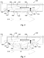
- the Figures 2 to 4 show the variation of the thickness of the circulation zone 120 of the boundary layer depending on the orientation of the auxiliary flow and / or the speed of the latter.
- the thickness is even greater than the speed of the injected gas 104 is high or the orientation of the gas flow has a certain angle.
- said angle is between 0 ° and 90 °, 0 ° corespondant substantially ejection aligned and opposed to the main flow 12, the injected auxiliary flow 104 opposes the main flow 12. This induces a frontal separation of the boundary layer and a large circulation zone 120 which depends on the speed of the gas injected.
- the auxiliary flow 104 is added with the main flow. This has the effect of reducing the size of the circulation zone 120.
- the boundary layer then behaves as a treadmill vis-à-vis the wall 110 in contact with the boundary layer.
- the gas of the auxiliary flow 104, 112, 109 is preferably air which makes it possible to avoid weighing the nacelle 1 of the invention by the transport of a particular gas.
- the injected air 104 can be recovered downstream of the nacelle 1 of the invention, for example in an area containing the turbojet engine 6 or in the vicinity of the latter.
- the air injected as an auxiliary flow can be captured on the hot primary flow of the turbojet engine so as to minimize the captured flow and have a significant energy. This air can be advantageously used to de-ice the wall 110 of the section.
- the injection means 102 are configured to vary the speed and / or the orientation of the secondary flow 104 by ejector effect induced by the auxiliary flow 104.
- the injection means 102 may comprise an ejection nozzle which makes it possible to inject simply and in little space the gas of the auxiliary flow 104.
- the ejection nozzle may be adjustable, which makes it possible to modify the thickness of the boundary layer 120. To do this, it is possible to adapt the angle of convergence between the flow of the injected gas and the main flow. To do this, the ejection nozzle can be connected to sensors connected to the turbojet engine 6 for changing the orientation of said nozzle as required.
- the injection means 102 may also comprise a gas sampling system 122 forming the auxiliary flow 104 comprising at least one valve 124 configured to vary the flow rate of the secondary air flow 104.
- the sampling system 122 typically comprises pipes as illustrated on the Figures 2 to 4 for conveying said gas to the injection means 102. As indicated above, in the case where the gas is air, the pipes can open on an area near the turbojet engine 6.
- valve or valves 124 may be controlled by sensors, in particular sensors connected to the turbojet engine 6, in particular to the FADEC. As a result, the injection of the gas into the space 3.10 is carried out so as to optimize the operation of the turbojet engine 6 according to the flight conditions.
- the use of valves 124 makes it possible to regulate the flow rate and the kinetic energy of the injected auxiliary flow 104 which makes it possible to modulate the distortion of the boundary layer produced in fine in the main stream 12 and thus to change the passage section by the single action on the valve (s) 124.
- the internal return zone delimits with the circulation zone a profile of the island boundary layer or in substantially hump.
- This profile is advantageously maintained by means of plates arranged substantially radially and aligned with the flow injected appropriately. These substantially longitudinal plates may be located in the injection zone but also in the suction zone where they reinforce the grids or the permeable walls.
- Suction by said suction means 106 mainly uses the vacuum generated by the injection means 102 located upstream of the suction means 106 which tends to draw the gas into the interior of the cavity from downstream to the upstream. This effect is known in particular as the ejection pump or ejector.
- the suction means 106 may be chosen from a monolithic perforated wall, a honeycomb cell wall, grids, in particular blade grids, trellises, one or more longitudinal or non-longitudinal slits, which allows efficient and space-saving suctioning. .
- the suction means may be in the form of suction orifices, in particular of oriented blade grate (s).
- suction orifices in particular of oriented blade grate (s).
- s oriented blade grate
- the injection means 102 and / or aspiration 106 can be regulated by a device for modifying the kinetic energy, the flow rate and the orientation of the auxiliary flow 104 and 112, which makes it possible to control the thickness of the circulation zone 120 of the boundary layer.
- a device for modifying the kinetic energy, the flow rate and the orientation of the auxiliary flow 104 and 112 which makes it possible to control the thickness of the circulation zone 120 of the boundary layer.
- a device for modifying the kinetic energy, the flow rate and the orientation of the auxiliary flow 104 and 112 which makes it possible to control the thickness of the circulation zone 120 of the boundary layer.
- a device for modifying the kinetic energy, the flow rate and the orientation of the auxiliary flow 104 and 112 which makes it possible to control the thickness of the circulation zone 120 of the boundary layer.
- substantially steerable suction grids, substantially steerable nozzles and a orifice of variable size by the use of a diaphragm, for example.
- the internal return zone 108 may be a cavity, in particular an annular cavity, comprising a downstream opening 130 configured to suck up at least a portion of the gas 112 from the auxiliary flow in contact with the air of the main stream 12 and an upstream outlet. 132 configured to allow the circulation of the injected gas 104 by the injection means 102 and the gas 109 flowing in the cavity.
- a cavity simplifies the installation of the modulation device 100 and does not increase the mass of the nacelle 1 of the invention.
- the wall 140 substantially facing the flow of injected gas 104 by the injection means 102 has a rounded or angular surface which allows to have the desired profile of the desired flow.
- the modulation device 100 may be disposed in the wall of the air intake lip 13 (see FIG. Figures 5a, 5b and 5c ), in the wall of the external structure 9 (see Figures 6a and 6b ) and / or in the wall of the internal structure 8 (see Figures 7a and 7b ).
- the internal return zone may advantageously encompass said air inlet lip 13, in particular at the edge of the air intake lip 13. attack of the nacelle, and thus ensures defrosting when the injected gas is at an appropriate temperature, especially when said gas is taken from the primary flow of the turbojet engine.
- the pooling of air inlet and defrost control functions thus makes it possible to gain significant mass.
- the outer front portion of the internal return zone may be constituted by the air intake lip. It is possible to modify the shape of the circulation zone of the boundary layer to create a necking at the beginning of the wall to be de-iced and to locate therein injection means (see FIG. figure 5c ).
- the hot gas used for defrosting can thus be injected at the beginning of the zone to be defrosted.
- the flow in contact with the wall is warmer and can be accelerated to the place for defrosting.
- the front wall of the air inlet can correspond to the upstream part of the internal return zone.
- the gas flow sucked by the suction means is less hot downstream of the injection.
- the downstream partition is less hot than that of the nacelle using a deicing device of the prior art. Defrosting is thus optimized.
- the circulation zone of the boundary layer where the thickness is maximum can be used as feed and flow distribution conduit. annex injected.
- one or more injection means can be added to those of the defrosting and an additional output can be added to the outer part of the nacelle 1, in particular at the level of the junction between the air inlet lip 13 and the outer panel of the middle section 4. This allows to discharge a portion of the flow used for defrosting if necessary. Deicing is typically performed during the take-off and descent phases where the section of the air intake lip 13 should be the smallest.
- the space is then the annular vein 10 formed by the walls of the fixed internal structure 8 and the external structure 9 or the air inlet 3 formed by the air intake lip 13.
- the modulation device 100 generates thrust forces that can contribute to optimizing the operation of the turbojet engine 6, in particular when said device 100 is installed in downstream section 7 in the walls of the fixed internal structure 8 and of the external structure 9.
- the modulation device 100 is installed in the walls of the air inlet lip 13 and depending on the thickness of an area called the "dead water” zone, it is possible to increase the speed of the main flow 12 so as to obtain a sonic neck capable of annihilating any noise nuisance due to the fan blades of the turbojet engine.
- the modulation device 100 is in a configuration that accelerates the speed of the main air flow 12 and thus blocks the noise passing through the neck sonic.
- the modulation device 100 of the embodiment of the figure 5b optimizes the thrust as a function of the speed of the aircraft.
- the adaptation of the size of the section of the main air flow 12 optimizes the operation of the turbojet engine 6 and the pressure experienced by the air inlet 3.
- the modulation device 100 makes it possible to increase the section of the space 3 in order to follow the regime of the turbojet engine 6 and to optimize it.
- the modulation device 100 can also be used to transfer energy to the boundary layer in case of crosswind with respect to the nacelle 1 of the invention, by positioning the boundary layer sufficiently upstream on the lip of the 13 and using the appropriate injection angle. This configuration makes it possible to resist a crosswind with a thinner aerodynamic profile and a lighter structure than in the prior art.
- Said device 100 can also serve as a particularly effective integrated deicing system by extending the internal return zone 108 to the entire air intake lip 13 to be defrosted.
- the modulation device 100 of the embodiments of the Figures 6a and 7a allows a strong injection by decreasing the ejection section of the main air flow 12. This configuration is generally the so-called cruise mode.
- the modulation device 100 of the embodiments of the Figures 6b and 7b allows on the other hand a low injection corresponding to an intense operating phase of the turbojet engine 6 coupled to an acoustic attenuation, especially during the takeoff phase.
- the flow of the auxiliary gas flow is optimized according to the turbojet engine speed and according to the configuration chosen.
- a decrease in the ejection section of the space 10 generates an acoustic attenuation and allows a very high rate of low-speed expansion of the turbojet engine 6 by optimizing the cycle of the latter at high dilution rate.
- the modulation device 100 advantageously makes it possible to replace the variable nozzles used in the downstream section of the nacelle 1 of the invention.
- the nacelle may comprise a modulation device of the invention or a plurality of modulation devices.
- the latter may be arranged at the same place or at different locations of the nacelle, for example at the level of the air intake lip and the external structure.
- the injected auxiliary flow can be injected differently in terms of both the ejection angle and the flow rate employed.
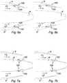
- the lower part 152 may have a circulation zone 120 thick relative to the upper part 150 , or also called 12h when viewed from the front of the air inlet 3, to prevent distortion of the flow on the lower part 152 of the fan 154 during take-off of the aircraft (see Figures 8a and 8b ).
- the upper part 150 may have a thick circulation zone with respect to the lower part 152 in order to avoid a divergence of the flow (see Figure 8c and 8d ), during the cruise regime of the aircraft.
- the one or both lateral parts of the nacelle when viewed from the front of the air inlet 3 may have a circulation zone 10 which is thicker than the circulation zone 120 of the upper part 150 and the lower part 152 to prevent distortion of the flow on the fan 154 (see figure 8e and 8f ), during takeoff in crosswinds.
- a device for modifying the section of the internal return zone 108 can be installed to optimize the structure of the flow of the auxiliary flow 109 and the size of the recirculation zone 120.
- said device may comprise a valve 160 disposed in the internal return zone 108 and / or a movable wall secured to one of the walls 110, 140 delimiting the internal return zone 108.
- the present invention can be used jointly in the air inlet and in the ejection outlet.
- the suction zone 106 can be located on the outer wall 170 of the nacelle, causing a bypass 171 of the trailing edge of the nacelle (see figure 10b ).
Landscapes
- Engineering & Computer Science (AREA)
- Chemical & Material Sciences (AREA)
- Combustion & Propulsion (AREA)
- Mechanical Engineering (AREA)
- General Engineering & Computer Science (AREA)
- Aviation & Aerospace Engineering (AREA)
- Physics & Mathematics (AREA)
- Geometry (AREA)
- Structures Of Non-Positive Displacement Pumps (AREA)
- Jet Pumps And Other Pumps (AREA)
Description
- La présente invention se rapporte à une nacelle pour un turboréacteur d'aéronef double flux ainsi qu'à un aéronef comportant une telle nacelle.
- Un aéronef est mu par plusieurs turboréacteurs logés chacun dans une nacelle abritant également un ensemble de dispositifs d'actionnement annexes liés à son fonctionnement et assurant diverses fonctions lorsque le turboréacteur est en fonctionnement ou à l'arrêt. Ces dispositifs d'actionnement annexes comprennent notamment un système mécanique d'actionnement d'inverseur de poussée.
- Une nacelle présente généralement une structure tubulaire suivant un axe longitudinal comprenant une entrée d'air en amont du turboréacteur, une section médiane destinée à entourer une soufflante du turboréacteur, une section aval abritant des moyens d'inversion de poussée et destinée à entourer la chambre de combustion du turboréacteur. La structure tubulaire est généralement terminée par une tuyère d'éjection dont la sortie est située en aval du turboréacteur.
- Les nacelles modernes sont destinées à abriter un turboréacteur double flux apte à générer par l'intermédiaire des pales de la soufflante en rotation un flux d'air chaud (également appelé « flux primaire ») issu de la chambre de combustion du turboréacteur, et un flux d'air froid (« flux secondaire ») qui circule à l'extérieur du turboréacteur à travers un passage annulaire, également appelé « veine annulaire».
- On entend ici par le terme « aval » la direction correspondant au sens du flux d'air froid pénétrant dans le turboréacteur. Le terme « amont » désigne la direction opposée.
- Ladite veine annulaire est formée par une structure externe, dite Outer Fixed Structure (OFS) et une structure interne concentrique, dite Inner Fixed Structure (IFS), entourant la structure du moteur proprement dite à l'aval de la soufflante. Les structures interne et externe appartiennent à la section aval. La structure externe peut comporter un ou plusieurs capots coulissants suivant l'axe longitudinal de la nacelle entre une position permettant l'échappement du flux d'air inversé et une position empêchant un tel échappement.
- Par ailleurs, outre sa fonction d'inversion de poussée, le capot coulissant appartient à la section arrière et présente un côté aval formant la tuyère d'éjection visant à canaliser l'éjection du flux d'air froid, désigné ci-après par « flux d'air principal ». Cette tuyère fournit la puissance nécessaire pour la propulsion en imprimant une vitesse aux flux d'éjection. Cette tuyère est associée à un système d'actionnement indépendant ou non de celui du capot permettant de faire varier et d'optimiser sa section en fonction de la phase de vol dans laquelle se trouve l'aéronef.
- Il peut s'avérer avantageux de diminuer la section d'entrée ou d'éjection du flux d'air principal dans l'espace formé par l'entrée d'air et la veine annulaire.
- Il est actuellement connu de diminuer la section d'éjection du flux d'air principal au niveau de la sortie de la veine annulaire par l'intermédiaire d'une tuyère variable formée par les capots coulissants de l'OFS. Une telle tuyère variable permet de moduler la poussée en faisant varier sa section de sortie en réponse à des variations du réglage de la puissance du turboréacteur et des conditions de vol.
- Cependant, la variation de la section d'éjection du flux d'air principal n'est pas toujours suffisamment rapide du fait de l'inertie des pièces mécaniques formant la tuyère variable, en cas de modification très rapide des conditions de vol.
- Il est connu des dispositifs permettant de moduler très rapidement la section d'éjection du flux d'air principal. Néanmoins, ce type de dispositifs augmente le poids de la nacelle et comprend des mécanismes complexes qui pénalisent souvent la fiabilité globale et les performances propulsives par des pertes aérodynamiques importantes. On vise à éviter ce type de défaut dans les avions civils où le gain de masse, l'augmentation de la fiabilité et des performances propulsives, ainsi que la diminution des pertes aérodynamiques sont favorisés. On connaît par ailleurs, du document
GB 1 298 069 - Il n'est pas connu de dispositif rapide et fiable permettant de modifier la section d'éjection du flux d'air principal dans la veine annulaire tout en conservant la masse de la nacelle et en offrant peu de perte aérodynamique.
- Un but de la présente invention est donc de fournir une nacelle ne présentant pas les inconvénients précités et répondant à ce besoin.
- A cet effet, selon un premier aspect, la présente invention a pour objet une nacelle pour un turboréacteur d'aéronef double flux présentant un axe longitudinal et une section arrière comportant une veine annulaire formant un espace de circulation d'un flux d'air principal délimitée par au moins une paroi d'une structure interne fixe et au moins une paroi d'une structure externe, ladite nacelle comprenant au moins un dispositif de modulation de la section transversale dudit espace disposé dans la paroi de la structure externe et/ou de la structure interne fixe et comportant :
- des moyens d'injection d'un flux annexe d'un gaz configurés pour faire varier l'orientation et/ou la vitesse dudit flux annexe;
- des moyens d'aspiration d'au moins une partie de ce flux annexe injecté ; et
- une zone de retour interne du flux annexe dans une ou plusieurs parois, ladite zone étant configurée pour permettre la circulation de la partie du flux annexe injecté et du flux annexe aspiré, et pour mettre en contact une partie du flux annexe injecté et du flux d'air principal.
- Par « flux d'air principal qui circule », on entend la pénétration du flux d'air principal dans l'espace, la circulation dudit flux d'air dans cet espace et l'ejection ou la sortie de ce flux d'air hors de cet espace.
- Par « section transversale », on entend une section réalisation transversalement par rapport à l'axe longitudinal de la nacelle.
- Le dispositif de modulation de la nacelle de l'invention engendre de manière ponctuelle et réversible une distortion de la couche limite formée par le contact entre le gaz du flux annexe et l'air du flux principal. L'épaisseur de cette distortion de la couche limite engendre une réduction de la section d'entrée ou de sortie ressentie par le flux principal.
- L'épaisseur de cette couche limite est plus ou moins grande en fonction des moyens d'injection et des moyens d'aspiration.
- Par conséquent, le dispositif de modulation de la nacelle de l'invention permet de manière simple, efficace, fiable et très rapide de modifier la taille de la section du flux d'air principal. Le temps de réponse du dispositif n'est pas limité par l'inertie de pièces mécaniques de grandes dimensions devant se mouvoir entre elles. On peut citer à titre d'exemple de pièce mécanique de grandes dimensions les panneau de capot coulissant d'inverseur de poussée ou le panneau interne d'entrée d'air.
- Selon d'autres caractéristiques de l'invention, la nacelle de l'invention comporte l'une ou plusieurs des caractéristiques optionnelles suivantes considérées seules ou selon toutes les combinaisons possibles :
- le gaz du flux annexe est de l'air ce qui permet d'éviter d'alourdir la nacelle par le transport d'un gaz particulier;
- les moyens d'injection comprennent une buse d'éjection ce qui permet d'éjecter simplement et en peu de place le gaz du flux annexe ;
- la buse d'éjection est orientable ce qui permet de modifier l'épaisseur de la couche limite formée par le contact entre le flux annexe et le flux principal, notamment en adaptant l'angle de confluence formé entre l'écoulement du gaz injecté et l'écoulement principal;
- les moyens d'injection comprennent un système de prélèvement de gaz comprenant au moins une vanne configurée pour faire varier le débit du flux annexe ;
- la ou les vannes sont contrôlées par des capteurs ce qui permet de modifier le flux annexe selon les modifications des conditions de vol ;
- les moyens d'aspiration sont choisis parmi une paroi perforée monolithique, une paroi à cellules alvéolaires, des grilles, notamment des grilles d'aube, des treillis, une ou plusieurs fentes longitudinales ou non ce qui permet une aspiration efficace et peu encombrante ;
- les moyens d'injection et/ou d'aspiration sont régulés par un dispositif de modification de l'energie cinétique, du débit et de l'orientation du flux annexe ce qui permet de contrôler l'épaisseur de la zone de circulation distordant sensiblement couche limite ;
- la zone de retour interne est une cavité comprenant une ouverture en aval configurée pour aspirer au moins une partie du gaz en contact avec l'air du flux principal et une sortie en amont configurée pour permettre la circulation du gaz injecté par les moyens d'injection et le gaz circulant dans la cavité, ce qui simplifie l'installation ;
- la paroi sensiblement en regard du flux annexe injecté par les moyens d'injection présente une surface arrondie ou anguleuse ce qui permet d'avoir un profil du flux annexe et la forme de la zone de circulation souhaités ;
- le dispositif de modulation est disposé dans la paroi d'une lèvre d'entrée d'air, d'une structure externe et/ou d'une structure interne ;
- L'invention sera davantage comprise à la lecture de la description non limitative qui va suivre, faite en référence aux figures ci-annexées.
- la
figure 1 est une coupe schématique partielle d'un mode de réalisation d'une nacelle de l'invention ; - les
figures 2 à 4 sont des coupes latérales schématiques partielles du mode de réalisation d'un dispositif de modulation de la nacelle de lafigure 1 dans lequel l'épaisseur de la couche limite est plus ou moins importante ; - les
figures 5a et 5b sont des coupes latérales schématiques partielles de la lèvre d'entrée d'air du mode de réalisation de la nacelle de lafigure 1 comportant le dispositif de modulation suivant respectivement lafigure 4 et lafigure 3 ; - la
figure 5c est une coupe latérale schématique partielle de la lèvre d'entrée d'air d'une variante desfigures 5a et 5b ; - les
figures 6a et 6b sont des coupes latérales schématiques partielles de la section aval du mode de réalisation de la nacelle de lafigure 1 comportant le dispositif de modulation suivant respectivement lafigure 4 et lafigure 3 monté sur la structure externe; - les
figures 7a et 7b sont des coupes latérales schématiques partielles de la section aval du mode de réalisation de la nacelle de lafigure 1 comportant le dispositif de modulation suivant respectivement lafigure 4 et lafigure 3 monté sur la structure interne fixe ; - les
figures 8a, 8c et 8e sont des coupes latérales schématiques partielles de la lèvre d'entrée d'air de différents modes de réalisation de la lèvre d'entrée d'air desfigures 5a à 5c ; - les
figures 8b, 8d et 8f sont des coupes transversale partielles de la lèvre d'entrée d'air des modes de réalisation respectifs desfigures 8a , 8c et 8e ; - la
figure 9 est une coupe latérale schématique partielle d'une variante du mode de réalsiation de lafigure 2 ; - les
figures 10a est une coupe latérale schématique partielle de la lèvre d'entrée d'air d'une variante de lafigure 5c ; - la
figure 10b est une coupe latérale schématique partielle de la section aval d'une variante de lafigure 6a . - Il est précisé que les exemples des
figures 5a à 5c ,8a à 8f et10a ne font pas partie de l'invention. - Comme représenté sur la
figure 1 , une nacelle 1 selon l'invention présente une forme sensiblement tubulaire selon un axe longitudinal Δ. La nacelle de l'invention 1 comprend une section amont 2 avec une lèvre d'entrée 13 d'air formant une entrée d'air 3, une section médiane 4 entourant une soufflante 5 d'un turboréacteur 6 et une section aval 7. La section aval 7 comprend une structure interne fixe 8 (IFS) entourant la partie amont du turboréacteur 6, une structure externe fixe (OFS) 9 et un capot mobile (non représenté) comportant des moyens d'inversion de poussée. - L'IFS 8 et l'OFS 9 délimite une veine annulaire 10 permettant le passage d'un flux d'air principal 12 pénétrant la nacelle 1 de l'invention au niveau de l'entrée d'air 3.
- La nacelle de l'invention 1 comporte donc des parois délimitant un espace, telle que l'entrée d'air 3 ou la veine annulaire 10, dans lequel le flux d'air principal 12 pénètre, circule et est éjecté.
- La nacelle 1 de l'invention se termine par une tuyère d'éjection 21 comprenant un module externe 22 et un module interne 24. Les modules interne 24 et externe 22 définissent un canal d'écoulement d'un flux d'air chaud 25 sortant du turboréacteur 6.
- Comme représenté sur la
figure 2 , la nacelle de l'invention 1 comprend au moins un dispositif de modulation 100 de la section dudit espace 3,10 comportant : - des moyens d'injection 102 d'un flux annexe d'un gaz 104 configurés pour faire varier l'orientation et/ou la vitesse dudit flux annexe 104;
- des moyens d'aspiration 106 d'au moins une partie de ce flux annexe injecté 104 ; et
- une zone de retour interne 108 du flux annexe 109 dans une ou plusieurs parois 110, ladite zone 108 étant configurée pour permettre la circulation de la partie du flux de gaz injecté 104 et du flux de gaz aspiré 112, et pour mettre en contact une partie du flux annexe injecté 104 et du flux d'air principal 12.
- Le dispositif de modulation 100 engendre de manière ponctuelle et réversible une zone de circulation 120 de la couche limite formée par le contact entre le gaz du flux annexe 104 et l'air du flux principal 12. Une partie perdue 119 de flux d'air secondaire comprise entre la ligne maximale d'écoulement 121 du flux annexe dans l'espace et la couche limite est entraînée avec le flux d'air principal 12. Cette partie perdue 119 peut être plus ou moins faible en fonction de l'épaisseur de la couche limite. Plus la zone de circulation 120 présente une hauteur importante, plus le débit d'injection est important. En effet, la perte de débit est importante dans cette configuration.
- La partie perdue 119 est entraînée par le flux principal 12 sans perturber le fonctionnement de la nacelle 1 de l'invention.
- L'utilisation de moyens d'injection 102 et d'aspiration 106 associés à une zone de retour interne 108 permet de réduire le débit injecté dans le flux principal 12 car une partie du flux est reprise par aspiration et circule dans la zone de retour interne 108. De ce fait, la perturbation dans le fonctionnement de la nacelle 1 due à l'injection d'un flux annexe par le dispositif de modulation 100 de l'invention est diminuée par rapport à la perturbation engendrée par une injection continue d'un flux de gaz sans aspiration de ce dernier.
- Le dispositif de l'invention permet en outre de circonscrire la partie du flux annexe turbulent ce qui n'affecte pas la performance de la nacelle 1 de l'invention.
- L'épaisseur de la zone de circulation 120 de la couche limite engendre une réduction de la section d'entrée ou de sortie ressentie par le flux principal 12. L'épaisseur de ladite zone de circulation 120 est plus ou moins grande en fonction des moyens d'injection 102 et des moyens d'aspiration 106.
- Par conséquent, le dispositif de modulation 100 permet de manière simple, efficace, fiable et très rapide de modifier la taille de la section de l'espace 3, 10. Le temps de réponse du dispositif 100 n'est pas limité par l'inertie de pièces mécaniques devant se mouvoir entre elles.
- De plus, la présence de moyens d'injection et d'aspiration d'un flux de gaz permet d'éviter un flux trop puissant avec un débit trop important. Un tel flux serait difficilement contrôlable. Ainsi, il apparaît un débit permanent du flux annexe 104 et 112 au niveau de la couche limite en contact avec le flux d'air principal 12. Un tel débit engendre des forces de poussée améliorant le fonctionnement du turboréacteur, notamment en cas de surchauffe de ce dernier.
- Les
figures 2 à 4 montrent la variation de l'épaisseur de la zone de circulation 120 de la couche limite en fonction de l'orientation du flux annexe et/ou de la vitesse de ce dernier. Ainsi, l'épaisseur est d'autant plus grande que la vitesse du gaz injecté 104 est élevée ou que l'orientation du flux du gaz présente un certain angle. Ainsi, à titre d'exemple, si ledit angle est compris entre 0° et 90°, 0° corespondant sensiblement à une éjection alignée et opposée au flux principal 12, le flux annexe injecté 104 s'oppose au flux principal 12. Ceci induit un décollement frontal de la couche limite et à une zone de circulation 120 de taille importante qui dépend de la vitesse du gaz injecté. Selon un autre exemple, si ledit angle est compris entre 90° et 180°, 180° correspondant à une éjection du flux annexe sensiblement tangentielle à la paroi dans le sens de l'écoulement du flux principal 12, le flux annexe 104 s'additionne avec le flux principal. Ceci a pour effet de diminuer la taille de la zone de circulation 120. La couche limite se comporte alors comme un tapis roulant vis-à-vis de la paroi 110 en contact avec la couche limite.. - Le gaz du flux annexe 104, 112, 109 est préférentiellement de l'air ce qui permet d'éviter d'alourdir la nacelle 1 de l'invention par le transport d'un gaz particulier. Ainsi, l'air injecté 104 peut être récupéré en aval de la nacelle 1 de l'invention, par exemple dans une zone contenant le turboréacteur 6 ou à proximité de ce dernier. Pour ce faire, l'air injecté en tant que flux annexe peut être capté sur le flux primaire chaud du turboréacteur de sorte à minimiser le débit capté et avoir une énergie importante. Cet air peut être avantageusement utilisé pour dégivrer la paroi 110 de la section.
- Les moyens d'injection 102 sont configurés pour faire varier la vitesse et/ou l'orientation du flux secondaire 104 par effet d'éjecteur induit par le flux annexe 104. Les moyens d'injection 102 peuvent comprendre une buse d'éjection ce qui permet d'injecter simplement et en peu de place le gaz du flux annexe 104.
- La buse d'éjection peut être orientable ce qui permet de modifier l'épaisseur de la couche limite 120. Pour ce faire, il est possible d'adapter l'angle de confluence entre l'écoulement du gaz injecté et l'écoulement principal. Pour ce faire, la buse d'éjection peut être reliée à des capteurs reliés au turboréacteur 6 permettant de modifier l'orientation de la dite buse au besoin.
- Les moyens d'injection 102 peuvent également comprendre un système de prélèvement 122 du gaz formant le flux annexe 104 comprenant au moins une vanne 124 configurée pour faire varier le débit du flux d'air secondaire 104. Le système de prélèvement 122 comprend typiquement des tuyaux comme illustrés sur les
figures 2 à 4 pour acheminer ledit gaz aux moyens d'injection 102. Comme indiqué plus haut, dans le cas où le gaz est de l'air, les tuyaux peuvent débouchés sur une zone à proximité du turboréacteur 6. - La ou les vannes 124 peuvent être contrôlées par des capteurs, notamment des capteurs reliés au turboréacteur 6, en particulier au FADEC. De ce fait, l'injection du gaz dans l'espace 3,10 est réalisée de manière à optimiser le fonctionnement du turboréacteur 6 en fonction des conditions de vol. L'utilisation de vannes 124 permet de régler le débit et l'énergie cinétique du flux annexe 104 injecté ce qui permet de moduler la distortion de la couche limite produite in fine dans le flux principal 12 et donc de changer la section de passage par la seule action sur la ou les vannes 124.
- Par ailleurs, la zone de retour interne délimite avec la zone de circulation un profil de la couche limite en îlot ou encore en forne sensiblement de bosse. Ce profil est avantageusement maintenu grâce à des plaques disposées de manière sensiblement radiale et alignés avec le flux injecté de manière appropriée. Ces plaques sensiblement longitudinales peuvent être situées dans la zone d'injection mais également dans la zone d'aspiration où elles renforcent les grilles ou les paroi perméables.
- L'aspiration par lesdits moyens d'aspiration 106 utilise principalement la dépression engendrée par les moyens d'injection 102 situés en amont des moyens d'aspiration 106 qui tend à aspirer le gaz à l'intéreur de la cavité de l'aval vers l'amont. Cette effet est notamment connu sous le nom de pompe à éjection ou éjecteur.
- Les moyens d'aspiration 106 peuvent être choisis parmi une paroi perforée monolithique, une paroi à cellules alvéolaires, des grilles, notamment des grilles d'aube, des treillis, une ou plusieurs fentes longitudinales ou non ce qui permet une aspiration efficace et peu encombrante.
- En particulier, les moyens d'aspiration peuvent être sous la forme d'orifices d'aspiration, notamment de grille(s) d'aube orientée(s). L'usage de telle(s) grilles d'aube orientée(s) permet de rendre l'aspiration encore plus efficace et moins encombrante
- Selon un mode de réalisation, les moyens d'injection 102 et/ou d'aspiration 106 peuvent être régulés par un dispositif de modification de l'energie cinétique, du débit et de l'orientation du flux annexe 104 et 112 ce qui permet de contrôler l'épaisseur de la zone de circulation 120 de la couche limite. A titre d'exemple, on peut citer des grilles d'aspiration sensiblement orientables, des buses sensiblement orientables et d'un orifice de taille variable par l'utilisation d'un diaphragme, par exemple.
- La zone de retour interne 108 peut être une cavité, notamment une cavité annulaire, comprenant une ouverture en aval 130 configurée pour aspirer au moins une partie du gaz 112 du flux annexe en contact avec l'air du flux principal 12 et une sortie en amont 132 configurée pour permettre la circulation du gaz injecté 104 par les moyens d'injection 102 et le gaz 109 circulant dans la cavité. Une telle cavité simplifie l'installation du dispositif de modulation 100 et n'alourdit pas non plus la masse de la nacelle 1 de l'invention.
- Selon un mode de réalisation, la paroi 140 sensiblement en regard du flux de gaz injecté 104 par les moyens d'injection 102 présente une surface arrondie ou anguleuse ce qui permet d'avoir le profil du flux annexe souhaité.
- Le dispositif de modulation 100 peut être disposé dans la paroi de la lèvre d'entrée d'air 13 (voir
figures 5a,5b et 5c ), dans la paroi de la structure externe 9 (voir lesfigures 6a et 6b ) et/ou dans la paroi de la structure interne 8 (voir lesfigures 7a et 7b ). - Dans le cas d'un dispositif de modulation 100 disposé dans la paroi de la lèvre d'entrée d'air 13, la zone de retour interne peut avantageusement englober ladite lèvre d'entrée d'air 13, notamment au niveau du bord d'attaque de la nacelle, et en assure ainsi le dégivrage lorsque le gaz injecté est à une température appropriée, notamment lorsque ledit gaz est prélevé au niveau du flux primaire du turboréacteur. La mutualisation des fonctions de contrôle de section d'entrée d'air et de dégivrage permet ainsi un gain de masse significatif.
- De manière plus précise, la partie avant externe de la zone de retour interne peut être constituée par la lèvre d'entrée d'air. Il est possible de modifier la forme de la zone de circulation de la couche limite pour créer une striction au début de la paroi à dégivrer et y localiser des moyens d'injection (voir
figure 5c ). - Le gaz chaud servant au dégivrage peut ainsi être injecté sensiblement au début de la zone à dégivrer. Au niveau de la paroi de la lèvre d'entrée d'air, l'écoulement en contact avec la paroi est plus chaud et peut être accéléré à l'endroit pour le dégivrage. Dans ce mode de réalisation, la cloison avant de l'entré d'air peut correspondre à la partie amont de la zone de retour interne.
- Le flux de gaz aspiré par les moyens d'aspiration est moins chaud en aval de l'injection. De ce fait, la cloison aval est moins chaude que celle de la nacelle utilisant un dispositif de dégivrage de l'art antérieur. Le dégivrage est ainsi optimisé.
- La zone de circulation de la couche limite où l'épaisseur est maximale peut être utilisée comme conduit d'amenée et de répartition du flux annexe injecté. Afin de découpler le système de dégivrage du contrôle de la section de sortie, un ou plusieurs moyens d'injection peuvent être adjoints à ceux du dégivrage et une sortie additionelle peut être rajoutée sur la partie externe de la nacelle 1, notamment au niveau de la jonction entre la lèvre d'entrée d'air 13 et le panneau externe de la section médiane 4. Ceci permet de décharger une partie du flux servant au dégivrage si besoin. Le dégivrage est typiquement effectué lors des phases de décollage et de descente où la section de la lèvre d'entrée d'air 13 devrait être la plus petite.
- De ce fait, l'espace est alors la veine annulaire 10 formée par les parois de la structure interne fixe 8 et la structure externe 9 ou l'entrée d'air 3 formée par la lèvre d'entrée d'air 13.
- Le dispositif de modulation 100 engendre des forces de poussée qui peuvent contribuer à optimiser le fonctionnement du turboréacteur 6, notamment lorsque ledit dispositif 100 est installer en section aval 7 dans les parois de la structure interne fixe 8 et de la structure externe 9.
- Dans le cas où le dispositif de modulation 100 est installé dans les parois de la lèvre d'entrée d'air 13 et en fonction de l'épaisseur d'une zone appelée zone « d'eau morte », il est possible d'augmenter la vitesse du flux principal 12 de sorte à obtenir un col sonique capable d'annihiler toute nuisance sonore due aux pales de la soufflante du turboréacteur.
- Comme cela est visible sur la
figure 5a , le dispositif de modulation 100 est dans une configuration qui accélère la vitesse du flux d'air principal 12 et donc bloque les nuisances sonores transitant par ce col sonique. - Le dispositif de modulation 100 du mode de réalisation de la
figure 5b permet d'optimiser la poussée en fonction de la vitesse de l'aéronef. - Dans ces deux modes de réalisation, l'adaptation de la taille de la section du flux d'air principal 12 permet d'optimiser le fonctionnement du turboréacteur 6 et de la pression subie par l'entrée d'air 3.
- En particulier, lors des phases de décollage et de descente de l'aéronef, le dispositif de modulation 100 permet d'augmenter la section de l'espace 3 afin de suivre le régime du turboréacteur 6 et d'optimiser ce dernier.
- Le dispositif de modulation 100 peut également servir à transférer de l'énergie à la couche limite en cas de vent de travers par rapport à la nacelle 1 de l'invention, en positionnant la couche limite suffisamment en amont sur la lèvre d'entre d'air 13 et en utilisant en angle d'injection approprié. Cette configuration permet de résister à un vent de travers avec un profil aérodynamique plus fin et une structure plus légère que dans l'art antérieur.
- Ledit dispositif 100 peut également servir de système de dégivrage intégré particulièrement efficace en étendant la zone de retour interne 108 à l'ensemble de la lèvre d'entrée d'air 13 à dégivrer.
- Le dispositif de modulation 100 des modes de réalisation des
figures 6a et 7a permet une forte injection en diminuant la section d'éjection du flux d'air principal 12. Cette configuration correspond en général au mode dit de croisière. - Le dispositif de modulation 100 des modes de réalisation des
figures 6b et 7b permet en revanche une faible injection correspondant à une phase de fonctionnement intense du turboréacteur 6 couplé à une atténuation acoustique, notamment lors de la phase de décollage. - Dans ces quatres modes de réalisation, le débit du flux annexe de gaz est optimisé en fonction du régime du turboréacteur et en fonction de la configuration choisie. Ainsi, une diminution de la section d'éjection de l'espace 10 engendre une atténuation acoustique et permet un très fort taux de détente à bas régime du turboréacteur 6 en optimisant le cycle de ce dernier à grand taux de dilution. Ainsi, le dispositif de modulation 100 permet de manière avantageuse de remplacer les tuyères variables utilisées en section aval de la nacelle 1 de l'invention.
- Selon un mode de réalisation non représenté, la nacelle peut comporter un dispositif de modulation de l'invention ou bien une pluralité de dispositifs de modulation. Dans le cas d'une pluralité de dispositifs, ces derniers peuvent être disposés à un même endroit ou à différents endroits de la nacelle, par exemple au niveau de la lèvre d'entrée d'air et de la structure externe. Dans ce cas, le flux annexe injecté peut être injecté de manière différente tant au niveau de l'angle d'éjection que du débit employé.
- Dans le cas d'une entrée d'air 3, la partie basse 152, ou encore appelée 6h lorsqu'on regarde de face l'entrée d'air 3, peut présenter une zone de circulation 120 épaisse par rapport à la partie haute 150, ou encore appelée 12h lorsqu'on regarde de face l'entrée d'air 3, afin d'éviter une distorsion de l'écoulement sur la partie basse 152 de la soufflante 154 lors du décollage de l'aéronef (voir
figures 8a et 8b ). - Dans le cas d'une entrée d'air 3, la partie haute 150 peut présenter une zone de circulation épaisse par rapport à la partie basse 152 afin d'éviter une divergence de l'écoulement (voir
figure 8c et 8d ), lors du régime de croisière de l'aéronef. - Dans le cas d'une entrée d'air 3, la ou les deux parties latérales de la nacelle lorsqu'on regarde de face l'entrée d'air 3 peuvent présenter une zone de circulation 10 plus épaisse que la zone de circulation 120 de la partie haute 150 et de la partie basse 152 afin d'éviter une distorsion de l'écoulement sur la soufflante 154 (voir
figure 8e et 8f ), lors du décollage en vent de travers. - Ainsi, il est possible de modifier la section de la lèvre d'entrée d'air sans complexifier la construction de la lèvre d'entrée d'air 3. En outre, il est possible d'avoir un gain de masse en réduisant l'épaisseur de bord d'attaque et la longueur de la lèvre d'entrée d'air 13.
- Comme représenté sur la
figure 9 , ans le cas d'un pilotage d'une entrée d'air 3 ou d'une tuyère d'éjection 21, un dispositif de modification de la section de la zone de retour interne 108 peut être installé pour optimiser la structure de l'écoulement du flux annexe 109 et la taille de la zone de recirculation 120. A titre d'exemple, ledit dispositif peut comporter une vanne 160 disposée dans la zone de retour interne 108 et/ou une paroi mobile assujettie à une des parois 110, 140 délimitant la zone de retour interne 108. - Dans le cas d'un pilotage de la circulation aérodynamique autour de la nacelle, la présente invention peut être utilisée conjointement dans l'entrée d'air et dans la sortie d'éjection. Dans ce cas, il peut être intéressant, sur l'entrée d'air, de localiser la zone d'injection 132 ou la zone d'aspiration 106 l'une à l'exterieur de l'entrée d'air 3 et l'autre à l'intérieur, selon le but recherché (voir
figure 10a ). De même, pour la tuyère d'éjection, la zone d'aspiration 106 peut être localisée sur la paroi externe 170 de la nacelle, engendrant un contournement 171 du bord de fuite de la nacelle (voirfigure 10b ).
Claims (10)
- Nacelle (1) pour un turboréacteur (6) d'aéronef double flux présentant un axe longitudinal (Δ) et une section arrière comportant une veine annulaire formant un espace (3) de circulation d'un flux d'air principal (12) délimitée par au moins une paroi d'une structure interne fixe (8), la structure interne fixe (8) étant destinée à entourer la structure du turboréacteur à l'aval d'une soufflante, et au moins une paroi d'une structure externe (9), ladite nacelle (1) comprenant au moins un dispositif de modulation (100) de la section transversale dudit espace (3) disposé dans la paroi de la structure externe et/ou de la structure interne fixe et comportant :- des moyens d'injection (102) d'un flux annexe (104) d'un gaz configurés pour faire varier l'orientation et/ou la vitesse dudit flux annexe (104);- des moyens d'aspiration (106) d'au moins une partie de ce flux annexe injecté (112) ; et- une zone de retour interne (108) du flux annexe (109) dans une ou plusieurs parois (110), ladite zone (108) étant configurée pour permettre la circulation de la partie du flux annexe injecté (104) et du flux annexe aspiré (112), et pour mettre en contact une partie du flux annexe de gaz injecté (104) et du flux d'air principal (12).
- Nacelle (1) selon la revendication précédente, dans laquelle le gaz du flux annexe (104, 112, 109) est de l'air.
- Nacelle (1) selon l'une quelconque des revendications précédentes, dans laquelle les moyens d'injection (102) comprennent une buse d'éjection.
- Nacelle (1) selon la revendication précédente, dans laquelle la buse d'éjection est orientable.
- Nacelle (1) selon l'une quelconque des revendications précédentes, dans laquelle les moyens d'injection (102) comprennent un système de prélèvement de gaz (122) comprenant au moins une vanne (124) configurée pour faire varier le débit du flux annexe (104, 109, 112).
- Nacelle (1) selon la revendication précédente, dans laquelle la ou les vannes (124) sont contrôlées par des capteurs.
- Nacelle (1) selon l'une quelconque des revendications précédentes, dans laquelle les moyens d'aspiration (106) sont choisis parmi une paroi perforée monolithique, une paroi à cellules alvéolaires, des grilles, notamment des grilles d'aube, des treillis, une ou plusieurs fentes longitudinales ou non.
- Nacelle (1) selon l'une quelconque des revendications précédentes, dans laquelle les moyens d'injection (102) et/ou d'aspiration (106) sont régulés par un dispositif de modification de l'energie cinétique, du débit et de l'orientation du flux annexe (104).
- Nacelle (1) selon l'une quelconque des revendications précédentes, dans laquelle la zone de retour interne (108) est une cavité comprenant une ouverture en aval (130) configurée pour aspirer au moins une partie du gaz en contact avec l'air du flux principal (12) et une sortie en amont (132) configurée pour permettre la circulation du gaz injecté (104) par les moyens d'injection (102) et le gaz (109) circulant dans la cavité.
- Nacelle (1) selon l'une quelconque des revendications précédentes, dans laquelle la paroi (140) sensiblement en regard du flux annexe de gaz injecté (104) par les moyens d'injection (102) présente une surface arrondie ou anguleuse.
Applications Claiming Priority (2)
| Application Number | Priority Date | Filing Date | Title |
|---|---|---|---|
| FR1150412A FR2970465B1 (fr) | 2011-01-19 | 2011-01-19 | Nacelle pour un turboreacteur d'aeronef double flux. |
| PCT/FR2012/050052 WO2012098322A2 (fr) | 2011-01-19 | 2012-01-09 | Nacelle pour un turboréacteur d'aéronef double flux |
Publications (2)
| Publication Number | Publication Date |
|---|---|
| EP2665909A2 EP2665909A2 (fr) | 2013-11-27 |
| EP2665909B1 true EP2665909B1 (fr) | 2017-09-13 |
Family
ID=44364739
Family Applications (2)
| Application Number | Title | Priority Date | Filing Date |
|---|---|---|---|
| EP12702596.3A Not-in-force EP2665909B1 (fr) | 2011-01-19 | 2012-01-09 | Nacelle pour un turboréacteur d'aéronef double flux |
| EP12702595.5A Withdrawn EP2665908A2 (fr) | 2011-01-19 | 2012-01-09 | Nacelle pour un turboréacteur d'aéronef double flux |
Family Applications After (1)
| Application Number | Title | Priority Date | Filing Date |
|---|---|---|---|
| EP12702595.5A Withdrawn EP2665908A2 (fr) | 2011-01-19 | 2012-01-09 | Nacelle pour un turboréacteur d'aéronef double flux |
Country Status (8)
| Country | Link |
|---|---|
| US (2) | US20150030445A1 (fr) |
| EP (2) | EP2665909B1 (fr) |
| CN (2) | CN103328800A (fr) |
| BR (2) | BR112013016652A2 (fr) |
| CA (2) | CA2824369A1 (fr) |
| FR (2) | FR2970465B1 (fr) |
| RU (2) | RU2013137710A (fr) |
| WO (2) | WO2012098322A2 (fr) |
Families Citing this family (16)
| Publication number | Priority date | Publication date | Assignee | Title |
|---|---|---|---|---|
| US9291101B2 (en) * | 2013-02-28 | 2016-03-22 | United Technologies Corporation | Gas turbine engine inlet wall design |
| US20160122005A1 (en) * | 2013-03-11 | 2016-05-05 | United Technologies Corporation | Embedded engines in hybrid blended wing body |
| FR3030452A1 (fr) * | 2014-12-17 | 2016-06-24 | Aircelle Sa | Nacelle pour un turboreacteur d'aeronef double flux |
| DE102015203218A1 (de) | 2015-02-23 | 2016-08-25 | Rolls-Royce Deutschland Ltd & Co Kg | Gasturbinentriebwerk mit Ölkühler in der Triebwerksverkleidung |
| US10308368B2 (en) | 2015-10-30 | 2019-06-04 | General Electric Company | Turbofan engine and method of reducing air flow separation therein |
| FR3045731B1 (fr) * | 2015-12-17 | 2018-02-02 | Safran Nacelles | Tuyere variable semi fluidique |
| WO2017192647A1 (fr) | 2016-05-03 | 2017-11-09 | Carrier Corporation | Entrée pour ventilateur axial |
| US10837362B2 (en) * | 2016-10-12 | 2020-11-17 | General Electric Company | Inlet cowl for a turbine engine |
| FR3095193B1 (fr) * | 2019-04-17 | 2022-06-24 | Safran Aircraft Engines | Procédé d’utilisation d’une entrée d’air de nacelle de turboréacteur comprenant une lèvre d’entrée d’air comprenant une portion mobile pour favoriser une phase d’inversion de poussée |
| US20200386107A1 (en) * | 2019-06-10 | 2020-12-10 | The Boeing Company | Mitigation of adverse flow conditions in a nacelle inlet |
| US11300049B2 (en) * | 2020-03-09 | 2022-04-12 | Rolls-Royce North American Technologies Inc. | Inlet guide vane draw heat exchanger system |
| US11333079B2 (en) | 2020-04-28 | 2022-05-17 | General Electric Company | Methods and apparatus to detect air flow separation of an engine |
| US11828237B2 (en) | 2020-04-28 | 2023-11-28 | General Electric Company | Methods and apparatus to control air flow separation of an engine |
| US11542866B2 (en) * | 2020-05-13 | 2023-01-03 | The Boeing Company | Adaptable flow control for engine nacelles |
| US12241410B1 (en) * | 2024-03-04 | 2025-03-04 | The Boeing Company | Engine nacelle anti-ice swirl system with unsteady fluid flow |
| CN117818871B (zh) * | 2024-03-04 | 2024-05-17 | 中国空气动力研究与发展中心高速空气动力研究所 | 被动式混合层流短舱应用方法 |
Family Cites Families (23)
| Publication number | Priority date | Publication date | Assignee | Title |
|---|---|---|---|---|
| US2709337A (en) * | 1952-03-28 | 1955-05-31 | United Aircraft Corp | Boundary layer control for the diffuser of a gas turbine |
| GB997863A (en) * | 1962-07-24 | 1965-07-07 | B S A Harford Pumps Ltd | Improvements relating to centrifugal pumps |
| US3402894A (en) * | 1966-06-01 | 1968-09-24 | United Aircraft Corp | Base-thrust nozzles |
| US3698642A (en) * | 1966-11-04 | 1972-10-17 | Thiokol Chemical Corp | Thrust vector control system |
| FR1505592A (fr) * | 1966-11-04 | 1967-12-15 | Snecma | Procédé pour atténuer les bruits émis par les compresseurs et soufflantes et dispositif pour la mise en oeuvre de ce procédé |
| US3572960A (en) * | 1969-01-02 | 1971-03-30 | Gen Electric | Reduction of sound in gas turbine engines |
| GB1298069A (en) * | 1969-05-03 | 1972-11-29 | Secr Defence | Air intake for a gas turbine engine |
| US3591087A (en) * | 1969-05-08 | 1971-07-06 | Rohr Corp | Apparatus for augmenting the thrust of an aircraft jet engine |
| US3684054A (en) * | 1971-02-25 | 1972-08-15 | Richard D Lemmerman | Jet engine exhaust augmentation unit |
| US5431533A (en) * | 1993-10-15 | 1995-07-11 | United Technologies Corporation | Active vaned passage casing treatment |
| US6179251B1 (en) * | 1998-02-06 | 2001-01-30 | Northrop Grumman Corporation | Thin inlet lip design for low drag and reduced nacelle size |
| WO2002036951A1 (fr) * | 2000-11-03 | 2002-05-10 | Pratt & Whitney Canada Corp. | Reduction du bruit par commande de l'etranglement du canal d'entree |
| US6655632B1 (en) * | 2002-08-27 | 2003-12-02 | General Electric Company | System and method for actively changing an effective flow-through area of an inlet region of an aircraft engine |
| US7047725B2 (en) * | 2003-05-28 | 2006-05-23 | Rohr, Inc. | Assembly and method for aircraft engine noise reduction |
| US7631483B2 (en) * | 2003-09-22 | 2009-12-15 | General Electric Company | Method and system for reduction of jet engine noise |
| GB2413158B (en) * | 2004-04-13 | 2006-08-16 | Rolls Royce Plc | Flow control arrangement |
| DE102004030597A1 (de) * | 2004-06-24 | 2006-01-26 | Rolls-Royce Deutschland Ltd & Co Kg | Strömungsarbeitsmaschine mit Aussenradstrahlerzeugung am Stator |
| US8480350B2 (en) * | 2006-10-12 | 2013-07-09 | United Technologies Corporation | Turbofan engine with variable bypass nozzle exit area and method of operation |
| US7870721B2 (en) * | 2006-11-10 | 2011-01-18 | United Technologies Corporation | Gas turbine engine providing simulated boundary layer thickness increase |
| US8033358B2 (en) * | 2007-04-26 | 2011-10-11 | Lord Corporation | Noise controlled turbine engine with aircraft engine adaptive noise control tubes |
| US8082726B2 (en) * | 2007-06-26 | 2011-12-27 | United Technologies Corporation | Tangential anti-swirl air supply |
| FR2925877B1 (fr) * | 2007-12-26 | 2009-12-04 | Aircelle Sa | Installation de systeme de guidage sur une nacelle d'aeronef. |
| US8234869B2 (en) * | 2010-08-09 | 2012-08-07 | Yen Tuan | Aviation engine inlet with tangential blowing for buzz saw noise control |
-
2011
- 2011-01-19 FR FR1150412A patent/FR2970465B1/fr not_active Expired - Fee Related
-
2012
- 2012-01-09 CA CA 2824369 patent/CA2824369A1/fr not_active Abandoned
- 2012-01-09 CA CA 2824367 patent/CA2824367A1/fr not_active Abandoned
- 2012-01-09 CN CN2012800058463A patent/CN103328800A/zh active Pending
- 2012-01-09 BR BR112013016652A patent/BR112013016652A2/pt not_active IP Right Cessation
- 2012-01-09 EP EP12702596.3A patent/EP2665909B1/fr not_active Not-in-force
- 2012-01-09 WO PCT/FR2012/050052 patent/WO2012098322A2/fr not_active Ceased
- 2012-01-09 CN CN2012800055516A patent/CN103314206A/zh active Pending
- 2012-01-09 BR BR112013015345A patent/BR112013015345A2/pt not_active IP Right Cessation
- 2012-01-09 WO PCT/FR2012/050051 patent/WO2012098321A2/fr not_active Ceased
- 2012-01-09 RU RU2013137710/06A patent/RU2013137710A/ru not_active Application Discontinuation
- 2012-01-09 RU RU2013137711/06A patent/RU2013137711A/ru not_active Application Discontinuation
- 2012-01-09 EP EP12702595.5A patent/EP2665908A2/fr not_active Withdrawn
- 2012-01-19 FR FR1250524A patent/FR2970466B1/fr active Active
-
2013
- 2013-07-18 US US13/945,023 patent/US20150030445A1/en not_active Abandoned
- 2013-07-19 US US13/946,316 patent/US20150030446A1/en not_active Abandoned
Non-Patent Citations (1)
| Title |
|---|
| None * |
Also Published As
| Publication number | Publication date |
|---|---|
| FR2970466B1 (fr) | 2013-01-04 |
| CA2824367A1 (fr) | 2012-07-26 |
| RU2013137710A (ru) | 2015-02-27 |
| FR2970466A1 (fr) | 2012-07-20 |
| FR2970465B1 (fr) | 2013-10-11 |
| BR112013015345A2 (pt) | 2016-09-20 |
| RU2013137711A (ru) | 2015-02-27 |
| WO2012098322A3 (fr) | 2012-09-13 |
| BR112013016652A2 (pt) | 2016-10-04 |
| US20150030446A1 (en) | 2015-01-29 |
| EP2665908A2 (fr) | 2013-11-27 |
| CN103314206A (zh) | 2013-09-18 |
| WO2012098321A2 (fr) | 2012-07-26 |
| EP2665909A2 (fr) | 2013-11-27 |
| CA2824369A1 (fr) | 2012-07-26 |
| US20150030445A1 (en) | 2015-01-29 |
| WO2012098321A3 (fr) | 2012-09-13 |
| WO2012098322A2 (fr) | 2012-07-26 |
| CN103328800A (zh) | 2013-09-25 |
| FR2970465A1 (fr) | 2012-07-20 |
Similar Documents
| Publication | Publication Date | Title |
|---|---|---|
| EP2665909B1 (fr) | Nacelle pour un turboréacteur d'aéronef double flux | |
| EP1018468B1 (fr) | Turbomachine avec un réducteur de vitesse équipé d'un dispositif de refroidissement | |
| EP1973779B1 (fr) | Turbomoteur à double flux pourvu d'un prérefroidisseur | |
| CA2389525C (fr) | Dispositif de propulsion a cycle variable par derivation de gaz pour avion supersonique et procede de fonctionnement | |
| EP2580121B1 (fr) | Nacelle de turboreacteur | |
| EP2115290B1 (fr) | Nacelle de réacteur d'aéronef et aéronef comportant une telle nacelle | |
| EP3325345B1 (fr) | Aeronef avec un ensemble propulsif comprenant une soufflante a l'arriere du fuselage | |
| FR2906313A1 (fr) | Reacteur a double flux. | |
| FR2750168A1 (fr) | Unite de propulsion pour avion, comportant un dispositif d'inversion de poussee | |
| EP4544167B1 (fr) | Inverseur de poussee comprenant au moins une membrane deployable de deviation | |
| EP2016274A1 (fr) | Nacelle pour turboreacteur double flux a grand taux de dilution | |
| EP3325771B1 (fr) | Aeronef comportant deux soufflantes contrarotatives a l'arriere d'un fuselage avec calage des aubes de la soufflante aval | |
| EP2569527B1 (fr) | Dispositif pour attenuer le bruit emis par le jet d'un moteur de propulsion d'un aeronef | |
| WO2010061071A2 (fr) | Nacelle integree sur aile volante | |
| FR3107563A1 (fr) | Ensemble propulsif pour aeronef comportant un systeme de ventilation | |
| EP3628590A1 (fr) | Dispositif de réduction voire de suppression du bruit tonal pour système de dégivrage de groupe propulsif d'aéronef | |
| FR3018863A1 (fr) | Dispositif d'inversion de poussee sans grille pour nacelle de turboreacteur d'aeronef | |
| FR3131939A1 (fr) | Bec de séparation de turbomachine axiale comprenant un passage de débit d’air de dégivrage s’étandant jusqu’au redresseur | |
| FR3030452A1 (fr) | Nacelle pour un turboreacteur d'aeronef double flux | |
| WO2021136900A1 (fr) | Inverseur de poussée à portes comprenant un déflecteur pour rediriger un flux d'air vers un empennage | |
| WO2021136903A1 (fr) | Inverseur de poussée à portes comprenant un déflecteur pour rediriger un flux d'air vers l'amont | |
| WO2014006303A1 (fr) | Procédé de commande d'une section de tuyère variable d'un aéronef |
Legal Events
| Date | Code | Title | Description |
|---|---|---|---|
| PUAI | Public reference made under article 153(3) epc to a published international application that has entered the european phase |
Free format text: ORIGINAL CODE: 0009012 |
|
| 17P | Request for examination filed |
Effective date: 20130705 |
|
| AK | Designated contracting states |
Kind code of ref document: A2 Designated state(s): AL AT BE BG CH CY CZ DE DK EE ES FI FR GB GR HR HU IE IS IT LI LT LU LV MC MK MT NL NO PL PT RO RS SE SI SK SM TR |
|
| DAX | Request for extension of the european patent (deleted) | ||
| 17Q | First examination report despatched |
Effective date: 20160527 |
|
| RAP1 | Party data changed (applicant data changed or rights of an application transferred) |
Owner name: SAFRAN NACELLES |
|
| GRAP | Despatch of communication of intention to grant a patent |
Free format text: ORIGINAL CODE: EPIDOSNIGR1 |
|
| INTG | Intention to grant announced |
Effective date: 20170607 |
|
| GRAS | Grant fee paid |
Free format text: ORIGINAL CODE: EPIDOSNIGR3 |
|
| GRAA | (expected) grant |
Free format text: ORIGINAL CODE: 0009210 |
|
| AK | Designated contracting states |
Kind code of ref document: B1 Designated state(s): AL AT BE BG CH CY CZ DE DK EE ES FI FR GB GR HR HU IE IS IT LI LT LU LV MC MK MT NL NO PL PT RO RS SE SI SK SM TR |
|
| REG | Reference to a national code |
Ref country code: GB Ref legal event code: FG4D Free format text: NOT ENGLISH |
|
| REG | Reference to a national code |
Ref country code: CH Ref legal event code: EP |
|
| REG | Reference to a national code |
Ref country code: IE Ref legal event code: FG4D Free format text: LANGUAGE OF EP DOCUMENT: FRENCH |
|
| REG | Reference to a national code |
Ref country code: AT Ref legal event code: REF Ref document number: 928411 Country of ref document: AT Kind code of ref document: T Effective date: 20171015 |
|
| REG | Reference to a national code |
Ref country code: DE Ref legal event code: R096 Ref document number: 602012037247 Country of ref document: DE |
|
| REG | Reference to a national code |
Ref country code: FR Ref legal event code: PLFP Year of fee payment: 7 |
|
| REG | Reference to a national code |
Ref country code: NL Ref legal event code: MP Effective date: 20170913 |
|
| REG | Reference to a national code |
Ref country code: LT Ref legal event code: MG4D |
|
| PG25 | Lapsed in a contracting state [announced via postgrant information from national office to epo] |
Ref country code: NO Free format text: LAPSE BECAUSE OF FAILURE TO SUBMIT A TRANSLATION OF THE DESCRIPTION OR TO PAY THE FEE WITHIN THE PRESCRIBED TIME-LIMIT Effective date: 20171213 Ref country code: LT Free format text: LAPSE BECAUSE OF FAILURE TO SUBMIT A TRANSLATION OF THE DESCRIPTION OR TO PAY THE FEE WITHIN THE PRESCRIBED TIME-LIMIT Effective date: 20170913 Ref country code: HR Free format text: LAPSE BECAUSE OF FAILURE TO SUBMIT A TRANSLATION OF THE DESCRIPTION OR TO PAY THE FEE WITHIN THE PRESCRIBED TIME-LIMIT Effective date: 20170913 Ref country code: FI Free format text: LAPSE BECAUSE OF FAILURE TO SUBMIT A TRANSLATION OF THE DESCRIPTION OR TO PAY THE FEE WITHIN THE PRESCRIBED TIME-LIMIT Effective date: 20170913 Ref country code: SE Free format text: LAPSE BECAUSE OF FAILURE TO SUBMIT A TRANSLATION OF THE DESCRIPTION OR TO PAY THE FEE WITHIN THE PRESCRIBED TIME-LIMIT Effective date: 20170913 |
|
| REG | Reference to a national code |
Ref country code: AT Ref legal event code: MK05 Ref document number: 928411 Country of ref document: AT Kind code of ref document: T Effective date: 20170913 |
|
| PG25 | Lapsed in a contracting state [announced via postgrant information from national office to epo] |
Ref country code: GR Free format text: LAPSE BECAUSE OF FAILURE TO SUBMIT A TRANSLATION OF THE DESCRIPTION OR TO PAY THE FEE WITHIN THE PRESCRIBED TIME-LIMIT Effective date: 20171214 Ref country code: RS Free format text: LAPSE BECAUSE OF FAILURE TO SUBMIT A TRANSLATION OF THE DESCRIPTION OR TO PAY THE FEE WITHIN THE PRESCRIBED TIME-LIMIT Effective date: 20170913 Ref country code: ES Free format text: LAPSE BECAUSE OF FAILURE TO SUBMIT A TRANSLATION OF THE DESCRIPTION OR TO PAY THE FEE WITHIN THE PRESCRIBED TIME-LIMIT Effective date: 20170913 Ref country code: BG Free format text: LAPSE BECAUSE OF FAILURE TO SUBMIT A TRANSLATION OF THE DESCRIPTION OR TO PAY THE FEE WITHIN THE PRESCRIBED TIME-LIMIT Effective date: 20171213 Ref country code: LV Free format text: LAPSE BECAUSE OF FAILURE TO SUBMIT A TRANSLATION OF THE DESCRIPTION OR TO PAY THE FEE WITHIN THE PRESCRIBED TIME-LIMIT Effective date: 20170913 |
|
| PG25 | Lapsed in a contracting state [announced via postgrant information from national office to epo] |
Ref country code: NL Free format text: LAPSE BECAUSE OF FAILURE TO SUBMIT A TRANSLATION OF THE DESCRIPTION OR TO PAY THE FEE WITHIN THE PRESCRIBED TIME-LIMIT Effective date: 20170913 |
|
| PG25 | Lapsed in a contracting state [announced via postgrant information from national office to epo] |
Ref country code: CZ Free format text: LAPSE BECAUSE OF FAILURE TO SUBMIT A TRANSLATION OF THE DESCRIPTION OR TO PAY THE FEE WITHIN THE PRESCRIBED TIME-LIMIT Effective date: 20170913 Ref country code: PL Free format text: LAPSE BECAUSE OF FAILURE TO SUBMIT A TRANSLATION OF THE DESCRIPTION OR TO PAY THE FEE WITHIN THE PRESCRIBED TIME-LIMIT Effective date: 20170913 Ref country code: RO Free format text: LAPSE BECAUSE OF FAILURE TO SUBMIT A TRANSLATION OF THE DESCRIPTION OR TO PAY THE FEE WITHIN THE PRESCRIBED TIME-LIMIT Effective date: 20170913 |
|
| PG25 | Lapsed in a contracting state [announced via postgrant information from national office to epo] |
Ref country code: IT Free format text: LAPSE BECAUSE OF FAILURE TO SUBMIT A TRANSLATION OF THE DESCRIPTION OR TO PAY THE FEE WITHIN THE PRESCRIBED TIME-LIMIT Effective date: 20170913 Ref country code: AT Free format text: LAPSE BECAUSE OF FAILURE TO SUBMIT A TRANSLATION OF THE DESCRIPTION OR TO PAY THE FEE WITHIN THE PRESCRIBED TIME-LIMIT Effective date: 20170913 Ref country code: SK Free format text: LAPSE BECAUSE OF FAILURE TO SUBMIT A TRANSLATION OF THE DESCRIPTION OR TO PAY THE FEE WITHIN THE PRESCRIBED TIME-LIMIT Effective date: 20170913 Ref country code: IS Free format text: LAPSE BECAUSE OF FAILURE TO SUBMIT A TRANSLATION OF THE DESCRIPTION OR TO PAY THE FEE WITHIN THE PRESCRIBED TIME-LIMIT Effective date: 20180113 Ref country code: EE Free format text: LAPSE BECAUSE OF FAILURE TO SUBMIT A TRANSLATION OF THE DESCRIPTION OR TO PAY THE FEE WITHIN THE PRESCRIBED TIME-LIMIT Effective date: 20170913 Ref country code: SM Free format text: LAPSE BECAUSE OF FAILURE TO SUBMIT A TRANSLATION OF THE DESCRIPTION OR TO PAY THE FEE WITHIN THE PRESCRIBED TIME-LIMIT Effective date: 20170913 |
|
| REG | Reference to a national code |
Ref country code: DE Ref legal event code: R097 Ref document number: 602012037247 Country of ref document: DE |
|
| PLBE | No opposition filed within time limit |
Free format text: ORIGINAL CODE: 0009261 |
|
| STAA | Information on the status of an ep patent application or granted ep patent |
Free format text: STATUS: NO OPPOSITION FILED WITHIN TIME LIMIT |
|
| PG25 | Lapsed in a contracting state [announced via postgrant information from national office to epo] |
Ref country code: DK Free format text: LAPSE BECAUSE OF FAILURE TO SUBMIT A TRANSLATION OF THE DESCRIPTION OR TO PAY THE FEE WITHIN THE PRESCRIBED TIME-LIMIT Effective date: 20170913 |
|
| 26N | No opposition filed |
Effective date: 20180614 |
|
| REG | Reference to a national code |
Ref country code: CH Ref legal event code: PL |
|
| PG25 | Lapsed in a contracting state [announced via postgrant information from national office to epo] |
Ref country code: MT Free format text: LAPSE BECAUSE OF FAILURE TO SUBMIT A TRANSLATION OF THE DESCRIPTION OR TO PAY THE FEE WITHIN THE PRESCRIBED TIME-LIMIT Effective date: 20170913 |
|
| PG25 | Lapsed in a contracting state [announced via postgrant information from national office to epo] |
Ref country code: LU Free format text: LAPSE BECAUSE OF NON-PAYMENT OF DUE FEES Effective date: 20180109 |
|
| REG | Reference to a national code |
Ref country code: IE Ref legal event code: MM4A |
|
| REG | Reference to a national code |
Ref country code: BE Ref legal event code: MM Effective date: 20180131 |
|
| PG25 | Lapsed in a contracting state [announced via postgrant information from national office to epo] |
Ref country code: CH Free format text: LAPSE BECAUSE OF NON-PAYMENT OF DUE FEES Effective date: 20180131 Ref country code: BE Free format text: LAPSE BECAUSE OF NON-PAYMENT OF DUE FEES Effective date: 20180131 Ref country code: LI Free format text: LAPSE BECAUSE OF NON-PAYMENT OF DUE FEES Effective date: 20180131 Ref country code: SI Free format text: LAPSE BECAUSE OF FAILURE TO SUBMIT A TRANSLATION OF THE DESCRIPTION OR TO PAY THE FEE WITHIN THE PRESCRIBED TIME-LIMIT Effective date: 20170913 |
|
| PG25 | Lapsed in a contracting state [announced via postgrant information from national office to epo] |
Ref country code: IE Free format text: LAPSE BECAUSE OF NON-PAYMENT OF DUE FEES Effective date: 20180109 |
|
| PG25 | Lapsed in a contracting state [announced via postgrant information from national office to epo] |
Ref country code: MC Free format text: LAPSE BECAUSE OF FAILURE TO SUBMIT A TRANSLATION OF THE DESCRIPTION OR TO PAY THE FEE WITHIN THE PRESCRIBED TIME-LIMIT Effective date: 20170913 |
|
| PG25 | Lapsed in a contracting state [announced via postgrant information from national office to epo] |
Ref country code: TR Free format text: LAPSE BECAUSE OF FAILURE TO SUBMIT A TRANSLATION OF THE DESCRIPTION OR TO PAY THE FEE WITHIN THE PRESCRIBED TIME-LIMIT Effective date: 20170913 |
|
| PG25 | Lapsed in a contracting state [announced via postgrant information from national office to epo] |
Ref country code: PT Free format text: LAPSE BECAUSE OF FAILURE TO SUBMIT A TRANSLATION OF THE DESCRIPTION OR TO PAY THE FEE WITHIN THE PRESCRIBED TIME-LIMIT Effective date: 20170913 Ref country code: HU Free format text: LAPSE BECAUSE OF FAILURE TO SUBMIT A TRANSLATION OF THE DESCRIPTION OR TO PAY THE FEE WITHIN THE PRESCRIBED TIME-LIMIT; INVALID AB INITIO Effective date: 20120109 |
|
| PG25 | Lapsed in a contracting state [announced via postgrant information from national office to epo] |
Ref country code: MK Free format text: LAPSE BECAUSE OF NON-PAYMENT OF DUE FEES Effective date: 20170913 Ref country code: CY Free format text: LAPSE BECAUSE OF FAILURE TO SUBMIT A TRANSLATION OF THE DESCRIPTION OR TO PAY THE FEE WITHIN THE PRESCRIBED TIME-LIMIT Effective date: 20170913 |
|
| PG25 | Lapsed in a contracting state [announced via postgrant information from national office to epo] |
Ref country code: AL Free format text: LAPSE BECAUSE OF FAILURE TO SUBMIT A TRANSLATION OF THE DESCRIPTION OR TO PAY THE FEE WITHIN THE PRESCRIBED TIME-LIMIT Effective date: 20170913 |
|
| PGFP | Annual fee paid to national office [announced via postgrant information from national office to epo] |
Ref country code: GB Payment date: 20211216 Year of fee payment: 11 Ref country code: FR Payment date: 20211215 Year of fee payment: 11 |
|
| PGFP | Annual fee paid to national office [announced via postgrant information from national office to epo] |
Ref country code: DE Payment date: 20211215 Year of fee payment: 11 |
|
| REG | Reference to a national code |
Ref country code: DE Ref legal event code: R119 Ref document number: 602012037247 Country of ref document: DE |
|
| GBPC | Gb: european patent ceased through non-payment of renewal fee |
Effective date: 20230109 |
|
| PG25 | Lapsed in a contracting state [announced via postgrant information from national office to epo] |
Ref country code: GB Free format text: LAPSE BECAUSE OF NON-PAYMENT OF DUE FEES Effective date: 20230109 Ref country code: DE Free format text: LAPSE BECAUSE OF NON-PAYMENT OF DUE FEES Effective date: 20230801 |
|
| PG25 | Lapsed in a contracting state [announced via postgrant information from national office to epo] |
Ref country code: FR Free format text: LAPSE BECAUSE OF NON-PAYMENT OF DUE FEES Effective date: 20230131 |