EP2671428B1 - Système de commande d'éclairage pour utilisation en environnement hospitalier - Google Patents
Système de commande d'éclairage pour utilisation en environnement hospitalier Download PDFInfo
- Publication number
- EP2671428B1 EP2671428B1 EP12703583.0A EP12703583A EP2671428B1 EP 2671428 B1 EP2671428 B1 EP 2671428B1 EP 12703583 A EP12703583 A EP 12703583A EP 2671428 B1 EP2671428 B1 EP 2671428B1
- Authority
- EP
- European Patent Office
- Prior art keywords
- signal
- control signal
- light
- controller
- patient
- Prior art date
- Legal status (The legal status is an assumption and is not a legal conclusion. Google has not performed a legal analysis and makes no representation as to the accuracy of the status listed.)
- Active
Links
Images


Classifications
-
- H—ELECTRICITY
- H05—ELECTRIC TECHNIQUES NOT OTHERWISE PROVIDED FOR
- H05B—ELECTRIC HEATING; ELECTRIC LIGHT SOURCES NOT OTHERWISE PROVIDED FOR; CIRCUIT ARRANGEMENTS FOR ELECTRIC LIGHT SOURCES, IN GENERAL
- H05B47/00—Circuit arrangements for operating light sources in general, i.e. where the type of light source is not relevant
- H05B47/10—Controlling the light source
- H05B47/105—Controlling the light source in response to determined parameters
- H05B47/115—Controlling the light source in response to determined parameters by determining the presence or movement of objects or living beings
-
- H—ELECTRICITY
- H05—ELECTRIC TECHNIQUES NOT OTHERWISE PROVIDED FOR
- H05B—ELECTRIC HEATING; ELECTRIC LIGHT SOURCES NOT OTHERWISE PROVIDED FOR; CIRCUIT ARRANGEMENTS FOR ELECTRIC LIGHT SOURCES, IN GENERAL
- H05B47/00—Circuit arrangements for operating light sources in general, i.e. where the type of light source is not relevant
- H05B47/10—Controlling the light source
-
- A—HUMAN NECESSITIES
- A61—MEDICAL OR VETERINARY SCIENCE; HYGIENE
- A61B—DIAGNOSIS; SURGERY; IDENTIFICATION
- A61B6/00—Apparatus or devices for radiation diagnosis; Apparatus or devices for radiation diagnosis combined with radiation therapy equipment
- A61B6/02—Arrangements for diagnosis sequentially in different planes; Stereoscopic radiation diagnosis
- A61B6/03—Computed tomography [CT]
- A61B6/037—Emission tomography
-
- Y—GENERAL TAGGING OF NEW TECHNOLOGICAL DEVELOPMENTS; GENERAL TAGGING OF CROSS-SECTIONAL TECHNOLOGIES SPANNING OVER SEVERAL SECTIONS OF THE IPC; TECHNICAL SUBJECTS COVERED BY FORMER USPC CROSS-REFERENCE ART COLLECTIONS [XRACs] AND DIGESTS
- Y02—TECHNOLOGIES OR APPLICATIONS FOR MITIGATION OR ADAPTATION AGAINST CLIMATE CHANGE
- Y02B—CLIMATE CHANGE MITIGATION TECHNOLOGIES RELATED TO BUILDINGS, e.g. HOUSING, HOUSE APPLIANCES OR RELATED END-USER APPLICATIONS
- Y02B20/00—Energy efficient lighting technologies, e.g. halogen lamps or gas discharge lamps
- Y02B20/40—Control techniques providing energy savings, e.g. smart controller or presence detection
Definitions
- the invention relates to a control system for controlling lighting and visual effects, in particular to such a system for use within a hospital environment.
- the workflow during an uptake period immediately before a PET (positron emission tomography) scan is very important for the quality of the scan.
- the patient is injected with a radioactively labeled sugar, often FDG, and subsequently scanned with either a standalone PET scanner or a combination of PET with either CT or MR for anatomical information.
- a number of steps have to be performed by the clinical personnel several of which require a high level of patient compliance. There is a need to make this workflow run more smoothly.
- Patient relaxation is of crucial importance in the time period immediately before and after the injection. If the patient is stressed in this period then the uptake will not be successful with FDG or radioactively labeled sugar being excessively consumed by overly stressed muscles and brain activity. Patients often get anxious during this uptake period due to the fact that they are in unfamiliar surroundings, are unsure about the examination and may have previous negative associations with clinical devices and or environments. Accordingly, there is a need to improving patient comfort and reducing anxiety before and during the examination.
- US 2010 315023 A1 discloses a hand rail with a support beam including LEDs that are turned on if sensors in the support beam detect that the beam has been touched.
- WO 2008/062384 A1 discloses a patient carrier for use in a radiation imaging suite, said carrier comprising sensors for detecting parameters like the weight or a movement of the patient or ambient temperature. Based on the sensor signals, an event initiator initiates events such as the display of an image, the emission of a sound, or the alarming of a caregiver.
- WO 2006/038169 A1 discloses a lighting system comprising a presence detector for detecting the presence of persons and a timer for measuring the duration of this presence. Moreover, the system comprises a pattern selector for selecting a particular lighting pattern based on the detected presence and its duration.
- US 2010060726 discloses a medical surgery or examination room and a method for illuminating such a room, wherein a substantial part of the room or the entire room is illuminated with colored lighting different from white lighting in order to achieve beneficial psychological effects or, primarily, to improve working conditions.
- green light may be provided behind the monitors used by a surgeon during operation and red light in a zone behind a surgeon during operation or examination.
- the lighting may be controlled by a computer with a touch screen interface.
- a light control system for controlling lighting in a room within a hospital environment is presented where the control system comprises
- the first sensor signal could be generated by a pressure sensor placed so that when a patient sits or lies on a bed then a signal indicative of the location of the patient is generated.
- Other patient location sensors may be used such as a video surveillance system that determines the location of a patient.
- a controllable light could be a light, e.g. a LED light, capable of being controlled via a control signal to emit light of different colors and intensities.
- the time-scheduler is able to delay the generation or outputting of the first control signal.
- the time-scheduler may be configured so that a sequence of different light effects (i.e. different colors and intensities) are generated in response to the first input signal where the time-scheduler controls the delay between the first input signal and the light effects, possibly the duration of each light effect, and possibly gradual changes of light effects.
- controllable light may be controlled so that firstly light which reduces patient anxiety is generated, secondly light which improves visibility of veins is generated so that the injection with radioactively labeled sugar can be performed accurately and without discomfort, and thirdly light which reduces patient anxiety and calms the patient is generated to ensure that the radioactively labeled sugar is only taken up by the tumor and not by stress induced muscle or brain activity.
- the timing of the generation of the control signal or different control signals may be beneficially for one or more of reducing patient anxiety, improving vein visibility and improving the workflow of the examination by tailoring the lighting settings to the specific stages of the examination procedure.
- the amount of delay between receipt of the first input signal to outputting or generating the first control signal may be stored in a storage medium or unit being accessible by the control system for retrieval of suitable delay values.
- the controller is configured for generating a time dependent first control signal, where a value of the first control signal changes over time so as to enable a gradual change of a color or an intensity of the controllable light. Accordingly, when the controllable light is controllable to change color or intensity in response to its input signal value, changing the analogue or digital value of the control signal from the controller enables the color and/or intensity to be gradually adjusted. In this way seamless transitions between different light effects may be achieved as well as gradual variations in light color and intensity in order to increase or reduce the calming effect of the lighting.
- the controller is configured for generating a second control signal for controlling a visual stimulation device, where the controller is configured for generating the second control signal in response to the first sensor signal and/or in response to a second sensor signal, where the first signal is indicative of a location of a patient and the second signal is indicative of a movement or a location of a clinical instrument or device, and where the time-scheduler is configured to time outputting of the second control signal relative to receipt of the first input signal or the second input signal.
- a visual stimulation device may be a monitor or a projector capable of displaying images. Accordingly, the controller may be able to output different images via the second control signal to the stimulation device for displaying images which provides e.g. a calming effect to the patient.
- the generation or outputting of the second control signal may be timed by the time-scheduler in response to receipt of the same first sensor signal as in the first aspect being indicative of a location of a patient or in response to a different sensor signal being indicative of a movement or a location of a clinical instrument or device.
- the controller may have inputs for receiving first and second input signals and respective outputs for making first and second control signals available for a light and a visual stimulation device, respectively.
- the controller has an input for receiving a second sensor signal indicative of a movement or a location of an intravenous needle, where the controller is configured to generate the first control signal in response to the first or the second sensor signal.
- the second sensor signal may be provided to the controller via the same input which is connected to receive the first sensor signal or via a separate input.
- the first control signal may be generated in response to the first or the second sensor signal, i.e. the first control signal is generated both when the first sensor signal is received and when the second sensor signal is received.
- the second sensor signal may be generated by an RF tag situated within a lead box storing the intravenous needle containing the radioactive fluid.
- the RF tag is detectable and the second sensor signal can be generated.
- the second sensor signal may be generated by a radioactive sensitive detector which is able to detect when the needle is removed from the lead box.
- control system comprises a storage including a number of selectable control schemes, where each control scheme defines the delay of outputting the first control signal relative to the first sensor signal and/or a time dependence of a change of a value of the first control signal, and where each control scheme is selectable via a user input device.
- a first control scheme may be configured to control the light in a way which is suitable for the uptake period before subsequent brain scans and a second control scheme may be configured for to control the light in a way which is suitable for breast scans.
- the brain scan control scheme may exclude high light intensities and rapid color changes as to reduce neurological stimulation as much as possible. Thus, the clinical personnel is able to select a control scheme which is suited for a particular examination.
- the first sensor signal is generated by a pressure sensor capable of detecting the presence of a patient in a bed or a sensor capable of detecting the presence of a radioactively labeled fluid to be injected into a vein of the patient.
- the first sensor may be an RF type sensor or a radiation sensor capable of sensing when the lead box storing the intravenous needle containing radioactive fluid is opened or when the needle is removed from the box.
- the controller further comprises an input for receiving a signal indicative of the heart rate of the patient, where the controller is configured for generating the second control signal for controlling the visual stimulation device in dependence of the signal indicative of the heart rate of the patient.
- the visual stimulation device may be used to effectively affect the heart rate of the patient, for example by displaying calming images if a too high heart rate is detected.
- the controller may be configured for generating the time dependence of the first control signal in dependence of the detected heart rate, e.g. for ensuring slow changes in intensity or color of the controllable light if a too high heart rate is detected.
- the breathing rate may be determined by a device and the controller.
- the controller is configured to first register the breathing rate and feedback this to the patient in the form of a breathing exercise, e.g. changing the light parameters with the breathing frequency. The rate is then slowly decreased to approximately 6 times per minute. This breathing rate is optimal for paced breathing and induction of a relaxed state in the patient.
- the controller is configured for generating a third control signal in dependence of the first input signal for controlling a computer controlled pointing device capable of locating the position of veins in a patient and pointing at a vein location suitable for injection of a fluid, where the time-scheduler is configured to delay outputting the third control signal relative to the time of receipt of the first sensor signal.
- the receipt of the first sensor signal triggers a delayed generation of the third control signal for starting detection of a vein location and pointing at a vein location suitable for injection of the radioactive fluid.
- the detection of vein locations may be performed by analyzing images of the arm of a patient and the pointing towards a suitable vein location may be performed by a laser pointing device.
- the third control signal may be generated in response an input signal indicative of a location of a patient or a clinical instrument or device.
- a second aspect of the invention relates to a light unit for use within a hospital environment, where the unit comprises
- the unit may comprise an audio device for generating music or other sounds.
- the control system and one or more of the monitor, the light and the audio device may be integrated into a single unit which may be mounted onto a wall.
- the light unit may also comprise any sensor for generating any of the first, second and third input signals.
- a third aspect of the invention relates to a method for controlling lighting in a room within a hospital environment, where the method comprises,
- the invention relates to a control system for an ambient light environment in a room in a hospital environment.
- the control system is configured to time and synchronize light effects of the ambient light environment in response to sensor signals from patient location sensors or other sensors for detecting if a clinical instrument is activated, moved or taken into use or for detecting heart rate.
- Light effects may be used by the clinical personnel to improve quality and speed of the examination and to create a calming atmosphere for the patient.
- different light effects are required at different times and for different durations. Therefore, timing of the light effects relative to sensor signals may improve workflow and patient comfort.
- PET imaging involves injecting patients with a radioactively labeled sugar, FDG, which is metabolized by the tumor at a faster rate than other muscles and organs. This highlights the tumor location and allows the tumor mass to be assessed by the clinician.
- FDG radioactively labeled sugar
- the tracer Since the uptake of the FDG tracer by the human body is essentially nonspecific, the tracer will gather at any location in the body that utilizes sugar. The patient is therefore required to remain as calm as possible (both mentally and physically) during the uptake period. This minimizes the sugar being consumed by non-tumor related features.
- the patient is initially introduced to the uptake room where the radioactive fluid will be injected, then the patient is instructed to remain still, quiet and calm for a period up to the injection, then the injection is given, and then the patient is again instructed to remain calm during the uptake until the scanning can be performed.
- Fig. 1 shows a light control system 100 for controlling lighting in a room within a hospital environment in response to input signals 111-113 from sensors 121-123.
- the lighting may include controllable lights 170 and possibly visual stimulation devices 190 such as TV monitors.
- the control system includes a controller 101 having an input 110 for receiving one or more sensor signals indicative of a location of a patient or a clinical instrument or device.
- the control system may have separate inputs 110 for receiving first, second and third sensor signals 111-113, respectively.
- the sensor signals are generated by sensors 121-123 such as sensors for detecting a location of a patient and for detecting position, removal, motion or use of clinical instrument or device.
- Location of a patient may be detected by a pressure sensor located in the mattras of a bed or a chair, an optical sensor or with camera and image analysis software. Detection of the location of clinical instruments such as intravenous needles and hypodermic needles and devices such a hand held scanners may be enabled by acceleration sensors or RF tags connected to the instrument or device.
- an intravenous or hypodermic needle containing a radioactively labeled fluid is stored in a lead box to avoid radioactive emissions.
- the opening of the lead box or removal of the needle from the box can beneficially be detected by exploiting that the lead box stops or reduces radioactive and electromagnetic emissions.
- a radiation sensor located outside the box can be used to detect the opening of the box.
- the room lighting is controlled by one or more control signals provided via one or more outputs 130.
- the controller generates the control signals in response to one or more of the sensor signals, e.g. in response to the first sensor signal 111.
- a time-scheduler is configured to delay or time the outputting of the one or more control signals. The delay is set relative to the time of receipt of one of the sensor signals, e.g. the first sensor signal 111.
- the time-scheduler 180 may be a separate component or integrated with the controller 101.
- the controller 101 and the time-scheduler 180 may be implemented as analogue or digital electronic circuits, as a computer program stored on a tangible media, e.g. a CD, designed to be executed by a processor or a computer, or they may be implemented as a combination of electronic circuits and a computer program.
- the inputs 110 and outputs 130 may be configured as input and output terminals of an electronic circuit which possibly is connectable to a computer, or by terminals of a computer.
- Fig. 2 provides an example of the function of the light control system 100.
- a patient lies on a bed and a first sensor signal is generated from the bed sensor.
- the controller In response to the first sensor signal 111, the controller generates a first control signal 131 for controlling the controllable light 170 into a first state to provide a comfortable light intensity and color.
- the first state may be invoked during the first period from t1 to t2.
- the value of the first control signal 131 may change over time so as to generate a gradual change of the color or the intensity of the controllable light. The gradual change may provide seamless transitions between different states of the controllable light or provide more interesting, yet calming light effects.
- a second control signal 132 may be generated in response to the first input signal 111 for controlling a monitor 190 for displaying images or videos, where the time-scheduler is configured to time outputting or generation of the second control signal 132 relative to receipt of the first input signal 111.
- the controller In response to the first sensor signal 111 the controller generates a first control signal 131 for controlling the controllable light into a second state to provide a green light which helps the clinical personnel to locate veins of the patient.
- the green light is maintained for a preset period up to time t3 or until the clinical personnel manually provides an input to the controller 101 via a user input device to force the controller to end this second light state.
- the generation of the first control signal 131 at time t2 for controlling the controllable light into a second state to provide a green light may be done in response to a second sensor signal 112 indicative of a movement or a location of a clinical instrument.
- the second sensor signal may be generated when the intravenous or hypodermic needle containing radioactively labeled fluid is removed from its lead box, e.g. by a radiation sensor.
- the radiation sensor may be located near the place where the injection is to be performed so that light changes to green light just before the injection.
- the first or second control signal for controlling the controllable light 170 or the controllable monitor 190 into a third state during the period from t3 to t4 may be generated in response to the first input signal 111 or preferably in response to the second input signal 112 generated in response to the movement of a clinical instrument.
- first or second control signals 131,132 invoke different states of the light 170 or the monitor 190, i.e. different intensity and color states or images.
- the first sensor may be a sensor capable of detecting the location of a patient, the presence of a patient in a bed, detecting the location or movement of clinical instruments, detecting the presence of a radioactively labeled fluid, or other sensors capable of detecting various changes in the environment within a room of a clinical environment.
- the time-scheduler generates the required delays necessary to obtain the correct timing for maintaining a given light state and changing between light states.
- the light controller 101 comprises an input for receiving a third input signal 113 indicative of the heart rate of the patient.
- a sensor 123 for detecting the heart rate may be conventional finger or breast pulsation detectors or a camera with an associated image analysis processor for detecting variations in blood flow.
- the third input signal may also be the breathing rate of the patient (sense either by a band or camera) and which allows the anxiety level of the patient to be assessed.
- the first or second control signal for controlling lights 170 or a monitor 190 may be generated in response to the third input signal 113 so that colors and light intensity or images from the monitor can be adjusted in response to the heart rate of the patient. For example, if the heart rate starts increasing the light intensity may be reduced or more relaxing images or music may be reproduced.
- the controller is configured for generating a third control signal 133 for controlling a computer controlled pointing device 192 capable of detecting location of veins of a patient and pointing at a vein location suitable for injection of a fluid.
- the third control signal may be generated in response to the first sensor signal in which case the time-scheduler delays outputting or generation of the third control signal relative to receipt of the first control signal.
- the third control signal 133 may be generated in response to the second sensor signal 112 indicative e.g. of the removal of an instrument for injecting radioactive labeled fluid.
- the control system 100 may comprise a storage 140 which may be integrated with the controller 101 where the storage is for storing a number of selectable control schemes.
- Each control scheme defines how any one or more of the first, second and third control signals 131-133 will be generated in response to any of the first, second or third input signals 111-113.
- each control scheme defines which of the first, second and third control signals 131-133 should be generated in response to any of the first, second or third input signals 111-113, and defines the delay from receipt of any of first, second or third input signals 111-113 to generation or outputting of any of the first, second or third control signals 131-133.
- the delay may be a time from zero up to several minutes and hours.
- the control scheme may define if and how values of the control signals should vary over time and the duration of any state of the light 170 or the monitor 190.
- Each of the control schemes may be selectable by a user of the control system 100 via a user input device 150 such as a touch pad or a keyboard. Accordingly, depending on the type of examination to be performed or the sex or age of the patient the most suitable control scheme can be selected. For example, for a brain scan examination a control scheme which excludes very bright light and rapid color changes may be selectable so as to reduce neurological stimulation as much as possible, whereas a for breast scan examination more stimulating light effects and images may be defined by a control scheme suitable for this type of examinations.
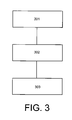
- Fig. 3 illustrates a method according to an embodiment of the invention which comprises the following steps:
- step 303 is not necessarily performed after generation of the control signal, but may be performed when or after the first sensor signal or other sensor signals is received and before or at the time of generation of the control signal.
- the control signal may be generated when the input signal is received, but the outputting of the generated control signal may be delayed.
- a delay may have to lapse before the control signal is generated.
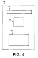
- Fig. 4 shows an ambient light unit 400 which comprises the light control system 100 and a monitor 190 for displaying images and/or a controllable light 170.
- the unit may be fixedly mounted in the hospital room, e.g. on a wall, so that the monitor 190 is visible for the patient lying on a bed and facing the ceiling.
- One or more lights 170 may be integrated in the unit 400 for background illumination of the room and for providing light directed towards the patient for situations where the patient is examined or where an injection is performed.
- the light unit 400 may be placed in the uptake room where the radioactive labeled fluid is injected.
- the scanning may be performed in the same room or in an adjacent room.
- a recovery room may be used in connection with the examination which is used for the patient to recover after the examination.
- the recovery room may have a separate light unit 400 installed.
- a single processor or other unit may fulfill one or more functions of several items recited in the claims, e.g. the generation and timing of the generation or outputting of the control signals in response to input signals.
- a computer program may be stored/distributed on a suitable medium, such as an optical storage medium or a solid-state medium supplied together with or as part of other hardware, but may also be distributed in other forms, such as via the Internet or other wired or wireless telecommunication systems.
Landscapes
- Circuit Arrangement For Electric Light Sources In General (AREA)
- Measuring And Recording Apparatus For Diagnosis (AREA)
- Measurement Of The Respiration, Hearing Ability, Form, And Blood Characteristics Of Living Organisms (AREA)
Claims (10)
- Système de commande de lumière (100) pour commander l'éclairage d'une pièce d'un environnement hospitalier, le système de commande comprenant :- un dispositif de commande (101) ayant une entrée (110) pour recevoir un premier signal de capteur (111) indicatif d'un emplacement ou d'un déplacement d'un instrument clinique, et une sortie (130) pour délivrer en sortie au moins un premier signal de commande sur une lumière pouvant être commandée (170), où le dispositif de commande est configuré pour générer le premier signal de commande en réponse au premier signal de capteur,- un programmateur temporel (180) configuré pour différer la délivrance en sortie ou la génération du premier signal de commande, où le différé est fixé par rapport à un moment de réception du premier signal de capteur.
- Système de commande de lumière selon la revendication 1, où le premier signal de commande (111) dépend du temps et où une valeur du premier signal de commande change avec le temps de manière à permettre un changement progressif d'une couleur ou d'une intensité de la lumière pouvant être commandé (170).
- Système de commande de lumière selon la revendication 1, où le dispositif de commande (101) a une entrée (110) pour recevoir un deuxième signal de capteur (112) indicatif d'un déplacement ou d'un emplacement d'une aiguille intraveineuse ou hypodermique, où le dispositif de commande est configuré pour générer le premier signal de commande en réponse au premier ou au deuxième signal de capteur.
- Système de commande de lumière selon la revendication 1, où le système de commande (101) comprend une unité de stockage (140) incluant un nombre de schémas de commande sélectionnables, où chaque schéma de commande définit le différé de la génération ou de la délivrance en sortie du premier signal de commande par rapport au premier signal de capteur et/ou une dépendance temporelle d'un changement d'une valeur du premier signal de commande, et où chaque schéma de commande est sélectionnable par le biais d'un dispositif d'entrée utilisateur (150).
- Système de commande de lumière selon la revendication 1, où le premier signal de capteur (111) est généré par un capteur (122) capable de détecter la présence d'un fluide radioactivement étiqueté à injecter dans une veine d'un patient.
- Système de commande de lumière selon la revendication 1, où le dispositif de commande est configuré pour générer un troisième signal de commande (133) en fonction du premier signal d'entrée (111) pour commander un dispositif de pointage commandé par ordinateur capable de détecter l'emplacement de veines d'un patient et pointer un emplacement de veine approprié pour l'injection d'un fluide, où le programmateur temporel est configuré pour différer la délivrance en sortie du troisième signal de commande par rapport au temps de réception du premier signal de capteur.
- Système de commande de lumière (100) selon la revendication 1, où le dispositif de commande (101) est configuré pour générer un deuxième signal de commande (132) pour commander un dispositif de stimulation visuelle (190), où le dispositif de commande (101) est configuré pour générer le deuxième signal de commande en réponse au premier signal de capteur et/ou en réponse à un deuxième signal de capteur (112), où le deuxième signal est indicatif d'un emplacement d'un patient, et où le programmateur temporel est configuré pour différer la délivrance en sortie ou la génération du deuxième signal de commande par rapport au moment de réception du premier signal d'entrée (111) ou du deuxième signal d'entrée (112).
- Système de commande de lumière selon la revendication 7, où le dispositif de commande comprend en outre une entrée (110) pour recevoir un signal indicatif de la fréquence cardiaque ou de la fréquence respiratoire du patient, et où le dispositif de commande est configuré pour générer le deuxième signal de commande (132) en fonction du signal indicatif de la fréquence cardiaque ou de la fréquence respiratoire du patient.
- Unité de commande de lumière (400) pour un environnement hospitalier, l'unité comprenant- un système de commande de lumière (100) selon la revendication 1, et- un écran (190) pour afficher des images et/ou une lumière pouvant être commandée (170).
- Procédé pour commander l'éclairage d'une pièce d'un environnement hospitalier, le procédé comprenant- la réception d'un premier signal de capteur (111) indicatif d'un emplacement d'un instrument ou dispositif clinique,- la génération d'un premier signal de commande (131) sur une lumière pouvant être commandée (170) par l'utilisation d'un dispositif de commande (101) configuré pour générer le premier signal de commande en réponse à la réception du premier signal de capteur,
où la génération ou délivrance en sortie du premier signal de commande est différée par rapport à un moment de réception du premier signal de capteur, où le différé est commandé par un programmateur temporel (180).
Priority Applications (1)
| Application Number | Priority Date | Filing Date | Title |
|---|---|---|---|
| EP12703583.0A EP2671428B1 (fr) | 2011-02-01 | 2012-01-27 | Système de commande d'éclairage pour utilisation en environnement hospitalier |
Applications Claiming Priority (3)
| Application Number | Priority Date | Filing Date | Title |
|---|---|---|---|
| EP11152935 | 2011-02-01 | ||
| PCT/IB2012/050383 WO2012104758A1 (fr) | 2011-02-01 | 2012-01-27 | Système de commande d'éclairage pour utilisation en environnement hospitalier |
| EP12703583.0A EP2671428B1 (fr) | 2011-02-01 | 2012-01-27 | Système de commande d'éclairage pour utilisation en environnement hospitalier |
Publications (2)
| Publication Number | Publication Date |
|---|---|
| EP2671428A1 EP2671428A1 (fr) | 2013-12-11 |
| EP2671428B1 true EP2671428B1 (fr) | 2016-10-05 |
Family
ID=45581944
Family Applications (1)
| Application Number | Title | Priority Date | Filing Date |
|---|---|---|---|
| EP12703583.0A Active EP2671428B1 (fr) | 2011-02-01 | 2012-01-27 | Système de commande d'éclairage pour utilisation en environnement hospitalier |
Country Status (7)
| Country | Link |
|---|---|
| US (1) | US9192022B2 (fr) |
| EP (1) | EP2671428B1 (fr) |
| JP (1) | JP5961631B2 (fr) |
| CN (1) | CN103348774B (fr) |
| BR (1) | BR112013019232A2 (fr) |
| RU (1) | RU2608180C2 (fr) |
| WO (1) | WO2012104758A1 (fr) |
Families Citing this family (14)
| Publication number | Priority date | Publication date | Assignee | Title |
|---|---|---|---|---|
| CN103237382B (zh) * | 2013-04-07 | 2015-08-19 | 四川长虹电器股份有限公司 | 一种智能家庭灯光控制方法及系统 |
| US20150116079A1 (en) * | 2013-10-24 | 2015-04-30 | GM Global Technology Operations LLC | Enhanced vehicle key fob |
| DE102014215211A1 (de) * | 2014-08-01 | 2016-02-04 | Art + Com Ag | Automatisches Erzeugen von visuellen Stimuli |
| EP3869922A1 (fr) | 2014-08-22 | 2021-08-25 | Lutron Technology Company LLC | Système de commande de charge sensible à l'emplacement d'un occupant et de dispositifs mobile |
| JP6580353B2 (ja) * | 2015-03-20 | 2019-09-25 | 旭化成ホームズ株式会社 | 照明付き建物 |
| CN112291879B (zh) | 2015-08-05 | 2024-03-01 | 路创技术有限责任公司 | 响应于占用者和/或移动设备的位置的负载控制系统 |
| EP4124178B1 (fr) | 2015-08-05 | 2025-02-19 | Lutron Technology Company LLC | Mise en service et contrôle de dispositifs de commande de charge |
| CN108476576B (zh) * | 2015-12-17 | 2020-04-14 | 飞利浦照明控股有限公司 | 照明系统和照明方法 |
| US11330693B2 (en) | 2016-05-30 | 2022-05-10 | Signify Holding B.V. | Illumination control |
| CN108235546B (zh) * | 2018-02-02 | 2024-08-27 | 上海联影医疗科技股份有限公司 | 医疗设备光环境系统和医疗系统 |
| CN111053356A (zh) * | 2018-10-17 | 2020-04-24 | 丽宝大数据股份有限公司 | 电子化妆镜装置及其显示方法 |
| JP7460299B2 (ja) * | 2019-04-09 | 2024-04-02 | トヨタホーム株式会社 | 照明設備の制御システム |
| US12186241B2 (en) | 2021-01-22 | 2025-01-07 | Hill-Rom Services, Inc. | Time-based wireless pairing between a medical device and a wall unit |
| US12279999B2 (en) | 2021-01-22 | 2025-04-22 | Hill-Rom Services, Inc. | Wireless configuration and authorization of a wall unit that pairs with a medical device |
Family Cites Families (15)
| Publication number | Priority date | Publication date | Assignee | Title |
|---|---|---|---|---|
| US5093769A (en) | 1990-10-04 | 1992-03-03 | Luntsford K Paul | Surgical lighting system |
| US20040052076A1 (en) | 1997-08-26 | 2004-03-18 | Mueller George G. | Controlled lighting methods and apparatus |
| US20040034933A1 (en) * | 2002-06-14 | 2004-02-26 | Smith Mitchell A. | Auto-locating procedural lights using a hospital bed |
| US7490957B2 (en) * | 2002-11-19 | 2009-02-17 | Denovo Lighting, L.L.C. | Power controls with photosensor for tube mounted LEDs with ballast |
| WO2005118982A2 (fr) | 2004-05-13 | 2005-12-15 | Nbbj Design Llp | Salle d'operation/salle d'intervention |
| PL1800523T3 (pl) | 2004-10-05 | 2020-11-16 | Signify Holding B.V. | Interaktywny system oświetleniowy |
| EP1892460A1 (fr) | 2006-08-21 | 2008-02-27 | Chromaviso ApS | Salle d'opération à éclairage coloré |
| US20100080431A1 (en) * | 2006-11-24 | 2010-04-01 | Koninklijke Philips Electronics N. V. | Smart patient-monitoring chair |
| CN101657180A (zh) * | 2007-03-14 | 2010-02-24 | 凯瑟琳·A·M·威茨曼 | 用于在患者体内定位饲管的方法和系统 |
| US8035320B2 (en) * | 2007-04-20 | 2011-10-11 | Sibert W Olin | Illumination control network |
| DE102008010990A1 (de) | 2008-02-25 | 2009-09-03 | Siemens Aktiengesellschaft | Einrichtung umfassend ein im Raum bewegbares, zu betrachtendes Objekt, insbesondere medizinische Untersuchungs- oder Behandlungseinrichtung mit einer im Raum bewegbaren Anzeigevorrichtung |
| JP5198945B2 (ja) * | 2008-06-20 | 2013-05-15 | テルモ株式会社 | 静脈表示装置 |
| WO2010063001A1 (fr) * | 2008-11-26 | 2010-06-03 | Wireless Environment, Llc | Dispositifs d’éclairage sans fil et applications associées |
| CN102413862B (zh) * | 2009-04-23 | 2014-05-07 | 松下电器产业株式会社 | 叫醒系统 |
| US8210705B2 (en) | 2009-06-16 | 2012-07-03 | Hok Product Design, Llc | Touch-sensitive lighted hand rail |
-
2012
- 2012-01-27 US US13/982,556 patent/US9192022B2/en active Active
- 2012-01-27 CN CN201280007377.9A patent/CN103348774B/zh active Active
- 2012-01-27 RU RU2013140382A patent/RU2608180C2/ru active
- 2012-01-27 EP EP12703583.0A patent/EP2671428B1/fr active Active
- 2012-01-27 JP JP2013550993A patent/JP5961631B2/ja active Active
- 2012-01-27 BR BR112013019232-1A patent/BR112013019232A2/pt not_active IP Right Cessation
- 2012-01-27 WO PCT/IB2012/050383 patent/WO2012104758A1/fr not_active Ceased
Also Published As
| Publication number | Publication date |
|---|---|
| CN103348774B (zh) | 2016-04-27 |
| BR112013019232A2 (pt) | 2021-06-01 |
| US9192022B2 (en) | 2015-11-17 |
| US20140232298A1 (en) | 2014-08-21 |
| RU2608180C2 (ru) | 2017-01-17 |
| JP2014513377A (ja) | 2014-05-29 |
| CN103348774A (zh) | 2013-10-09 |
| WO2012104758A1 (fr) | 2012-08-09 |
| RU2013140382A (ru) | 2015-03-10 |
| EP2671428A1 (fr) | 2013-12-11 |
| JP5961631B2 (ja) | 2016-08-02 |
Similar Documents
| Publication | Publication Date | Title |
|---|---|---|
| EP2671428B1 (fr) | Système de commande d'éclairage pour utilisation en environnement hospitalier | |
| CN112292082B (zh) | 用于医学成像的位置反馈指示符 | |
| US7839975B2 (en) | X-ray computerized tomography apparatus, breathing indication apparatus and medical imaging apparatus | |
| JP5329788B2 (ja) | X線コンピュータ断層撮影装置、呼吸指示装置及び医用画像撮影装置 | |
| KR101623834B1 (ko) | 의료 영상 촬영과 관련된 컨텐츠를 제공하기 위한 방법 및 그 장치 | |
| CN103239253B (zh) | 医用图像诊断装置 | |
| CN101541244A (zh) | 智能患者监测椅 | |
| KR101676020B1 (ko) | 의료 영상 기기 및 이에 포함되는 갠트리의 동작 정보 제공 방법 | |
| KR101788742B1 (ko) | 자기 공명 영상 촬영을 위한 파라미터 정보 출력 방법 및 장치 | |
| CN115844435A (zh) | 灌注成像 | |
| CN112204616B (zh) | 用于医学成像的自动化对象监测 | |
| CA3226235A1 (fr) | Systeme de retroaction biologique audio-visuelle de surface (savb) destine a la gestion de mouvement | |
| JP2006141497A (ja) | 患部を描画する方法及び患部描画システム | |
| CN214208363U (zh) | 一种具有手势监视和校准功能的手骨龄成像系统 | |
| JP2018166856A (ja) | 磁場データ処理システム | |
| Crepps | Limited field of view CBCT in specialty endodontic practice: an Eye tracking pilot study | |
| CN108462824A (zh) | 采集图像的方法及采集医学图像的系统 | |
| Smith et al. | Immersive Mixed Reality Simulator for CT Scan Preparation: Enhancing Patient Emotional and Physical Readiness | |
| WO2014016719A1 (fr) | Appareil de régulation de stimuli ambiants au niveau d'un patient | |
| JP2025035707A (ja) | 医用情報処理装置、医用情報プログラム、及び、x線診断装置 | |
| KR20160052517A (ko) | 의료 영상 촬영과 관련된 컨텐츠를 제공하기 위한 방법 및 그 장치 | |
| JP2024176659A (ja) | 医用画像診断装置及び医用画像診断装置の作動方法 | |
| Geller | Food and Drug Administration Issues New Guidance and Reclassifications | |
| KR20150024376A (ko) | 의료 영상 기기 및 이에 포함되는 갠트리의 동작 정보 제공 방법 |
Legal Events
| Date | Code | Title | Description |
|---|---|---|---|
| PUAI | Public reference made under article 153(3) epc to a published international application that has entered the european phase |
Free format text: ORIGINAL CODE: 0009012 |
|
| 17P | Request for examination filed |
Effective date: 20130902 |
|
| AK | Designated contracting states |
Kind code of ref document: A1 Designated state(s): AL AT BE BG CH CY CZ DE DK EE ES FI FR GB GR HR HU IE IS IT LI LT LU LV MC MK MT NL NO PL PT RO RS SE SI SK SM TR |
|
| DAX | Request for extension of the european patent (deleted) | ||
| GRAP | Despatch of communication of intention to grant a patent |
Free format text: ORIGINAL CODE: EPIDOSNIGR1 |
|
| INTG | Intention to grant announced |
Effective date: 20160428 |
|
| GRAS | Grant fee paid |
Free format text: ORIGINAL CODE: EPIDOSNIGR3 |
|
| GRAA | (expected) grant |
Free format text: ORIGINAL CODE: 0009210 |
|
| AK | Designated contracting states |
Kind code of ref document: B1 Designated state(s): AL AT BE BG CH CY CZ DE DK EE ES FI FR GB GR HR HU IE IS IT LI LT LU LV MC MK MT NL NO PL PT RO RS SE SI SK SM TR |
|
| REG | Reference to a national code |
Ref country code: GB Ref legal event code: FG4D |
|
| REG | Reference to a national code |
Ref country code: CH Ref legal event code: EP |
|
| REG | Reference to a national code |
Ref country code: AT Ref legal event code: REF Ref document number: 835570 Country of ref document: AT Kind code of ref document: T Effective date: 20161015 |
|
| REG | Reference to a national code |
Ref country code: IE Ref legal event code: FG4D |
|
| REG | Reference to a national code |
Ref country code: DE Ref legal event code: R096 Ref document number: 602012023707 Country of ref document: DE |
|
| REG | Reference to a national code |
Ref country code: FR Ref legal event code: PLFP Year of fee payment: 6 |
|
| REG | Reference to a national code |
Ref country code: NL Ref legal event code: MP Effective date: 20161005 |
|
| REG | Reference to a national code |
Ref country code: LT Ref legal event code: MG4D |
|
| PG25 | Lapsed in a contracting state [announced via postgrant information from national office to epo] |
Ref country code: LV Free format text: LAPSE BECAUSE OF FAILURE TO SUBMIT A TRANSLATION OF THE DESCRIPTION OR TO PAY THE FEE WITHIN THE PRESCRIBED TIME-LIMIT Effective date: 20161005 |
|
| REG | Reference to a national code |
Ref country code: AT Ref legal event code: MK05 Ref document number: 835570 Country of ref document: AT Kind code of ref document: T Effective date: 20161005 |
|
| PG25 | Lapsed in a contracting state [announced via postgrant information from national office to epo] |
Ref country code: SE Free format text: LAPSE BECAUSE OF FAILURE TO SUBMIT A TRANSLATION OF THE DESCRIPTION OR TO PAY THE FEE WITHIN THE PRESCRIBED TIME-LIMIT Effective date: 20161005 Ref country code: NO Free format text: LAPSE BECAUSE OF FAILURE TO SUBMIT A TRANSLATION OF THE DESCRIPTION OR TO PAY THE FEE WITHIN THE PRESCRIBED TIME-LIMIT Effective date: 20170105 Ref country code: GR Free format text: LAPSE BECAUSE OF FAILURE TO SUBMIT A TRANSLATION OF THE DESCRIPTION OR TO PAY THE FEE WITHIN THE PRESCRIBED TIME-LIMIT Effective date: 20170106 Ref country code: LT Free format text: LAPSE BECAUSE OF FAILURE TO SUBMIT A TRANSLATION OF THE DESCRIPTION OR TO PAY THE FEE WITHIN THE PRESCRIBED TIME-LIMIT Effective date: 20161005 |
|
| PG25 | Lapsed in a contracting state [announced via postgrant information from national office to epo] |
Ref country code: PT Free format text: LAPSE BECAUSE OF FAILURE TO SUBMIT A TRANSLATION OF THE DESCRIPTION OR TO PAY THE FEE WITHIN THE PRESCRIBED TIME-LIMIT Effective date: 20170206 Ref country code: ES Free format text: LAPSE BECAUSE OF FAILURE TO SUBMIT A TRANSLATION OF THE DESCRIPTION OR TO PAY THE FEE WITHIN THE PRESCRIBED TIME-LIMIT Effective date: 20161005 Ref country code: NL Free format text: LAPSE BECAUSE OF FAILURE TO SUBMIT A TRANSLATION OF THE DESCRIPTION OR TO PAY THE FEE WITHIN THE PRESCRIBED TIME-LIMIT Effective date: 20161005 Ref country code: AT Free format text: LAPSE BECAUSE OF FAILURE TO SUBMIT A TRANSLATION OF THE DESCRIPTION OR TO PAY THE FEE WITHIN THE PRESCRIBED TIME-LIMIT Effective date: 20161005 Ref country code: IS Free format text: LAPSE BECAUSE OF FAILURE TO SUBMIT A TRANSLATION OF THE DESCRIPTION OR TO PAY THE FEE WITHIN THE PRESCRIBED TIME-LIMIT Effective date: 20170205 Ref country code: PL Free format text: LAPSE BECAUSE OF FAILURE TO SUBMIT A TRANSLATION OF THE DESCRIPTION OR TO PAY THE FEE WITHIN THE PRESCRIBED TIME-LIMIT Effective date: 20161005 Ref country code: RS Free format text: LAPSE BECAUSE OF FAILURE TO SUBMIT A TRANSLATION OF THE DESCRIPTION OR TO PAY THE FEE WITHIN THE PRESCRIBED TIME-LIMIT Effective date: 20161005 Ref country code: BE Free format text: LAPSE BECAUSE OF FAILURE TO SUBMIT A TRANSLATION OF THE DESCRIPTION OR TO PAY THE FEE WITHIN THE PRESCRIBED TIME-LIMIT Effective date: 20161005 Ref country code: HR Free format text: LAPSE BECAUSE OF FAILURE TO SUBMIT A TRANSLATION OF THE DESCRIPTION OR TO PAY THE FEE WITHIN THE PRESCRIBED TIME-LIMIT Effective date: 20161005 Ref country code: FI Free format text: LAPSE BECAUSE OF FAILURE TO SUBMIT A TRANSLATION OF THE DESCRIPTION OR TO PAY THE FEE WITHIN THE PRESCRIBED TIME-LIMIT Effective date: 20161005 |
|
| REG | Reference to a national code |
Ref country code: DE Ref legal event code: R097 Ref document number: 602012023707 Country of ref document: DE |
|
| PG25 | Lapsed in a contracting state [announced via postgrant information from national office to epo] |
Ref country code: DK Free format text: LAPSE BECAUSE OF FAILURE TO SUBMIT A TRANSLATION OF THE DESCRIPTION OR TO PAY THE FEE WITHIN THE PRESCRIBED TIME-LIMIT Effective date: 20161005 Ref country code: SK Free format text: LAPSE BECAUSE OF FAILURE TO SUBMIT A TRANSLATION OF THE DESCRIPTION OR TO PAY THE FEE WITHIN THE PRESCRIBED TIME-LIMIT Effective date: 20161005 Ref country code: RO Free format text: LAPSE BECAUSE OF FAILURE TO SUBMIT A TRANSLATION OF THE DESCRIPTION OR TO PAY THE FEE WITHIN THE PRESCRIBED TIME-LIMIT Effective date: 20161005 Ref country code: EE Free format text: LAPSE BECAUSE OF FAILURE TO SUBMIT A TRANSLATION OF THE DESCRIPTION OR TO PAY THE FEE WITHIN THE PRESCRIBED TIME-LIMIT Effective date: 20161005 Ref country code: CZ Free format text: LAPSE BECAUSE OF FAILURE TO SUBMIT A TRANSLATION OF THE DESCRIPTION OR TO PAY THE FEE WITHIN THE PRESCRIBED TIME-LIMIT Effective date: 20161005 |
|
| PLBE | No opposition filed within time limit |
Free format text: ORIGINAL CODE: 0009261 |
|
| STAA | Information on the status of an ep patent application or granted ep patent |
Free format text: STATUS: NO OPPOSITION FILED WITHIN TIME LIMIT |
|
| PG25 | Lapsed in a contracting state [announced via postgrant information from national office to epo] |
Ref country code: IT Free format text: LAPSE BECAUSE OF FAILURE TO SUBMIT A TRANSLATION OF THE DESCRIPTION OR TO PAY THE FEE WITHIN THE PRESCRIBED TIME-LIMIT Effective date: 20161005 Ref country code: SM Free format text: LAPSE BECAUSE OF FAILURE TO SUBMIT A TRANSLATION OF THE DESCRIPTION OR TO PAY THE FEE WITHIN THE PRESCRIBED TIME-LIMIT Effective date: 20161005 Ref country code: BG Free format text: LAPSE BECAUSE OF FAILURE TO SUBMIT A TRANSLATION OF THE DESCRIPTION OR TO PAY THE FEE WITHIN THE PRESCRIBED TIME-LIMIT Effective date: 20170105 |
|
| REG | Reference to a national code |
Ref country code: CH Ref legal event code: PL |
|
| 26N | No opposition filed |
Effective date: 20170706 |
|
| PG25 | Lapsed in a contracting state [announced via postgrant information from national office to epo] |
Ref country code: MC Free format text: LAPSE BECAUSE OF FAILURE TO SUBMIT A TRANSLATION OF THE DESCRIPTION OR TO PAY THE FEE WITHIN THE PRESCRIBED TIME-LIMIT Effective date: 20161005 |
|
| PG25 | Lapsed in a contracting state [announced via postgrant information from national office to epo] |
Ref country code: CH Free format text: LAPSE BECAUSE OF NON-PAYMENT OF DUE FEES Effective date: 20170131 Ref country code: LI Free format text: LAPSE BECAUSE OF NON-PAYMENT OF DUE FEES Effective date: 20170131 |
|
| REG | Reference to a national code |
Ref country code: IE Ref legal event code: MM4A |
|
| PG25 | Lapsed in a contracting state [announced via postgrant information from national office to epo] |
Ref country code: SI Free format text: LAPSE BECAUSE OF FAILURE TO SUBMIT A TRANSLATION OF THE DESCRIPTION OR TO PAY THE FEE WITHIN THE PRESCRIBED TIME-LIMIT Effective date: 20161005 Ref country code: LU Free format text: LAPSE BECAUSE OF NON-PAYMENT OF DUE FEES Effective date: 20170127 |
|
| REG | Reference to a national code |
Ref country code: FR Ref legal event code: PLFP Year of fee payment: 7 |
|
| PG25 | Lapsed in a contracting state [announced via postgrant information from national office to epo] |
Ref country code: IE Free format text: LAPSE BECAUSE OF NON-PAYMENT OF DUE FEES Effective date: 20170127 |
|
| PG25 | Lapsed in a contracting state [announced via postgrant information from national office to epo] |
Ref country code: MT Free format text: LAPSE BECAUSE OF NON-PAYMENT OF DUE FEES Effective date: 20170127 |
|
| PG25 | Lapsed in a contracting state [announced via postgrant information from national office to epo] |
Ref country code: HU Free format text: LAPSE BECAUSE OF FAILURE TO SUBMIT A TRANSLATION OF THE DESCRIPTION OR TO PAY THE FEE WITHIN THE PRESCRIBED TIME-LIMIT; INVALID AB INITIO Effective date: 20120127 |
|
| PG25 | Lapsed in a contracting state [announced via postgrant information from national office to epo] |
Ref country code: CY Free format text: LAPSE BECAUSE OF NON-PAYMENT OF DUE FEES Effective date: 20161005 |
|
| PG25 | Lapsed in a contracting state [announced via postgrant information from national office to epo] |
Ref country code: MK Free format text: LAPSE BECAUSE OF FAILURE TO SUBMIT A TRANSLATION OF THE DESCRIPTION OR TO PAY THE FEE WITHIN THE PRESCRIBED TIME-LIMIT Effective date: 20161005 |
|
| PG25 | Lapsed in a contracting state [announced via postgrant information from national office to epo] |
Ref country code: TR Free format text: LAPSE BECAUSE OF FAILURE TO SUBMIT A TRANSLATION OF THE DESCRIPTION OR TO PAY THE FEE WITHIN THE PRESCRIBED TIME-LIMIT Effective date: 20161005 |
|
| PG25 | Lapsed in a contracting state [announced via postgrant information from national office to epo] |
Ref country code: AL Free format text: LAPSE BECAUSE OF FAILURE TO SUBMIT A TRANSLATION OF THE DESCRIPTION OR TO PAY THE FEE WITHIN THE PRESCRIBED TIME-LIMIT Effective date: 20161005 |
|
| REG | Reference to a national code |
Ref country code: DE Ref legal event code: R084 Ref document number: 602012023707 Country of ref document: DE |
|
| PGFP | Annual fee paid to national office [announced via postgrant information from national office to epo] |
Ref country code: GB Payment date: 20260126 Year of fee payment: 15 |
|
| PGFP | Annual fee paid to national office [announced via postgrant information from national office to epo] |
Ref country code: DE Payment date: 20260127 Year of fee payment: 15 |
|
| PGFP | Annual fee paid to national office [announced via postgrant information from national office to epo] |
Ref country code: FR Payment date: 20260126 Year of fee payment: 15 |