EP2672332B1 - Verbessertes System eines drehbaren Außenrings (einer Uhr) - Google Patents
Verbessertes System eines drehbaren Außenrings (einer Uhr) Download PDFInfo
- Publication number
- EP2672332B1 EP2672332B1 EP12171071.9A EP12171071A EP2672332B1 EP 2672332 B1 EP2672332 B1 EP 2672332B1 EP 12171071 A EP12171071 A EP 12171071A EP 2672332 B1 EP2672332 B1 EP 2672332B1
- Authority
- EP
- European Patent Office
- Prior art keywords
- ring
- bezel
- spring
- recess
- toothing
- Prior art date
- Legal status (The legal status is an assumption and is not a legal conclusion. Google has not performed a legal analysis and makes no representation as to the accuracy of the status listed.)
- Active
Links
Images



Classifications
-
- G—PHYSICS
- G04—HOROLOGY
- G04B—MECHANICALLY-DRIVEN CLOCKS OR WATCHES; MECHANICAL PARTS OF CLOCKS OR WATCHES IN GENERAL; TIME PIECES USING THE POSITION OF THE SUN, MOON OR STARS
- G04B19/00—Indicating the time by visual means
- G04B19/28—Adjustable guide marks or pointers for indicating determined points of time
-
- G—PHYSICS
- G04—HOROLOGY
- G04B—MECHANICALLY-DRIVEN CLOCKS OR WATCHES; MECHANICAL PARTS OF CLOCKS OR WATCHES IN GENERAL; TIME PIECES USING THE POSITION OF THE SUN, MOON OR STARS
- G04B19/00—Indicating the time by visual means
- G04B19/28—Adjustable guide marks or pointers for indicating determined points of time
- G04B19/283—Adjustable guide marks or pointers for indicating determined points of time on rotatable rings, i.e. bezel
-
- G—PHYSICS
- G04—HOROLOGY
- G04B—MECHANICALLY-DRIVEN CLOCKS OR WATCHES; MECHANICAL PARTS OF CLOCKS OR WATCHES IN GENERAL; TIME PIECES USING THE POSITION OF THE SUN, MOON OR STARS
- G04B19/00—Indicating the time by visual means
- G04B19/28—Adjustable guide marks or pointers for indicating determined points of time
- G04B19/283—Adjustable guide marks or pointers for indicating determined points of time on rotatable rings, i.e. bezel
- G04B19/286—Adjustable guide marks or pointers for indicating determined points of time on rotatable rings, i.e. bezel with locking means to prevent undesired rotations in both directions
-
- G—PHYSICS
- G01—MEASURING; TESTING
- G01C—MEASURING DISTANCES, LEVELS OR BEARINGS; SURVEYING; NAVIGATION; GYROSCOPIC INSTRUMENTS; PHOTOGRAMMETRY OR VIDEOGRAMMETRY
- G01C23/00—Combined instruments indicating more than one navigational value, e.g. for aircraft; Combined measuring devices for measuring two or more variables of movement, e.g. distance, speed or acceleration
Definitions
- the present invention relates to a timepiece comprising a middle part closed by a bottom and an ice, said timepiece further comprising a rotating bezel system attached to said middle part.
- the technical field of the invention is the technical field of fine mechanics.
- the present invention relates to a rotating bezel for a timepiece.
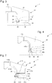
- Rotating eyewear systems 2 known, visible to the figure 1 , comprise a rotating bezel 4 in the form of an annular piece having an upper face and a lower face, the upper face being the face visible by the user.
- This bezel comprises, on its lower surface, a notch 6.
- the rotating bezel system further comprises a spring means 8.
- This spring means 8 is inserted between the rotating bezel and the middle part 3 of the timepiece 1 when the bezel 4 is mounted to force on the middle part of the timepiece.
- This spring means 8 is in the form of a flat ring comprising, on its face facing the notch of the bezel, lamellae. These slats are arranged to have an inclination relative to the plane of the flat ring. These slats have a certain elasticity so that the spring means act on the rotating bezel to exert a vertical force. This vertical force tends to push the bezel out of the middle of the timepiece.
- these strips serve to cooperate with the notching of the underside of the bezel.
- the slats and notching are then configured so that the bezel can rotate in one direction.
- the slats oppose the rotation of the telescope if the user tries to rotate the telescope in the wrong direction.
- the bezel and the spring means are made of steel which has the advantage of having a good life and being inexpensive.
- This bezel is attached to the middle of the watch case by hunting.
- the middle part having a peripheral shoulder in which said rotating bezel system is placed, the vertical wall of said shoulder having a peripheral groove 10.
- the bezel is an annular piece having, on its underside, a peripheral rim.
- This flange is provided with a continuous projection 12 extending along said flange towards the axial center of the telescope.
- a disadvantage of this system is that it requires a large force to mount said rotating bezel system. Indeed, when the bezel is force-fitted on said middle so that the continuous projection fits into the peripheral groove, significant stresses are applied to the bezel. These constraints can, if they are poorly applied, lead to deformations of the telescope and therefore a malfunction of the rotating bezel system.
- the object of the invention is to overcome the drawbacks of the prior art by proposing to provide a timepiece rotating bezel system whose assembly on the watch case is simpler, while imposing less stress on said system and which makes it easier to disassemble.
- the invention relates to a timepiece comprising, inter alia, a middle closed by a bottom and an ice, said case having a peripheral shoulder in which is arranged a groove, said groove being disposed on a face of the shoulder parallel to the central axis of the middle part, said timepiece comprising a rotating bezel system rotatably mounted on said peripheral shoulder, characterized in that said rotating bezel system comprises a bezel ring provided with at least a first recess disposed on a face of the telescope intended to come opposite said groove when said rotating bezel system is mounted on the middle part, said rotating bezel system further comprising spring means extending both in said at less a first recess of the bezel and both in the groove of the middle to maintain the rotating bezel system to the ca rrure of the timepiece.
- a first advantage of the present invention is to allow the rotating bezel system according to the invention to be easier to assemble.
- the system according to the present invention is in the form of a pre-assembled system. It is then understood that the various elements constituting the rotating bezel system are assembled together and that it suffices, after that, to fix said system to the middle part of the watch case. Thus, the storage and transport of the rotating bezel systems are simpler because they are already mounted
- a second advantage is that the present invention allows a mounting requiring fewer constraints. Indeed, as the means are the means to retain the system of rotating bezel at the middle of the watch case, the stress exerted during the assembly is partly absorbed. This stress is absorbed by the spring which will deform and facilitate assembly.
- the spring means comprise a spring ring in the form of an open ring having at least one zone having a minimum radius and an area having a maximum radius so that the zone having a maximum radius cooperates with said at least one first recess and that the zone having a minimum radius cooperates with the groove of the peripheral shoulder.
- the rotating bezel system further comprises a toothed element having a toothing arranged to cooperate with a corresponding toothing arranged on the spring means for indexing at the angular position of the bezel.
- the bezel comprises a second recess in which the toothed element is arranged.
- said spring ring is a flat ring whose teeth are arranged on the outer wall of said at least one zone having a minimum radius, the first and second recesses then being merged.
- said spring ring comprises two ends, one of which has a raised portion, said raised portion comprising a vertically oriented curved portion and a flat portion parallel to said spring ring, said flat portion comprising, on its outer wall. , the toothing cooperating with the toothed element.
- the bezel is made in at least two parts and comprises a bezel ring and a support ring both having a complementary profile so that the assembly of the bezel ring to the ring of support makes it possible to form the first and second recesses combined.
- the bezel is made in at least two parts and comprises a bezel ring and a support ring both having a complementary profile so that the assembly of the bezel ring to the ring of support makes it possible to form the second recess, said support ring comprising the first recess.
- said spring ring comprises three zones having a minimum radius angularly distributed.
- the zones having a minimum radius of said spring ring are angularly distributed.
- said toothing is arranged on each zone having a maximum radius.
- the present invention proceeds from the general inventive idea of providing a rotating bezel system which is easier to assemble.
- a timepiece 1 visible at the figure 2 comprises a middle 30 closed by a bottom 31 and a mirror 32.
- This middle part 30 comprises a peripheral shoulder 34 defined by a side wall 36 and a base 38.
- This shoulder 34 defines a location in which the rotating bezel system 20 is placed.
- the rotating bezel system 20, visible at the figure 3 includes a telescope 40 which is the visible part and manipulated by the user.
- the rotating bezel system 20 also comprises a toothed element 60 arranged at the bezel 40 and spring means 80 cooperating with the toothed element 60 to allow rotation of the rotating bezel system 20 relative to the middle part 30 of the part watchmaking 1.
- the spring means 80 are also used to maintain the rotating bezel system 20 at the middle 30 of the watch case 1.
- the spring means 80 are in the form of a multi-level spring, in three dimensions.
- the rotating bezel system 20 of this embodiment comprises a telescope 41.
- This telescope 41 is for example in the form of a ring comprising an upper face 41a and a lower face 41b. From this lower face 41b, a peripheral rim 42 extends perpendicular to the plane of the telescope 41.
- This rim device 42 includes an inner side wall 42a and an outer side wall 42b.
- the inner side wall 42a includes a second recess 44 having a parallelepipedal profile such as a square or rectangular profile. This second recess 44 traverses the entire length of said rim 42 so as to be circular. In this second recess 44 is arranged the toothed element 60.
- This toothed element 60 may be in the form of a toothing 61 made directly in said first recess of the rim or, as in the example shown, in the form of a toothed ring 62 carrying, on its inner face, a toothing 63.
- This toothed ring 62 is placed in said second recess 44.
- Means for angularly securing said toothed ring 62 to the bezel 41 are provided, such as for example solder or glue. Nevertheless, it can be provided that the toothing 63 forming the toothed element 60 can be made directly on the inner side wall 42a of the peripheral flange 42, the latter not including a second recess 44.
- the spring means 80 visible to figures 5 and 6 are in the form of a spring ring 82.
- This spring ring has an upper face and a lower face, said upper face being the visible face from a top view when said spring ring is placed on any plane.
- the latter comprises an open ring 800 comprising at least one zone having a radius of curvature smaller than the radius of curvature of said non-closed ring. It is then understood that said spring ring comprises at least one zone 802 having a maximum radius and at least one zone 804 having a minimum radius. In the case shown in figure 5 , the spring ring comprises three zones 802 having a maximum radius spaced angularly regularly.
- Said open ring 800 also has, at one of its ends 806, an elevation 808.
- said end has an axial or vertical curvature so that this end is raised and parallel to the plane of the spring ring 800.
- raised portion then comprises a curved portion 808a oriented axially and a flat portion 808b parallel to said spring ring 82.
- this curvature extends from the upper face of the spring ring 82.
- This raised portion 808 comprises, on its outer face, a toothing 810.
- This toothing 810 is complementary to the toothing of the toothed element 60 that is to say the toothing 63 of the toothed ring 62 or the toothing 61. Indeed, when the spring ring 82 is mounted in the rotating bezel system 20, the elevation of the ring spring 82 is calculated such that the latter is opposite the toothed ring 62.
- the latter comprises a spring recess 46 having a square or rectangular profile also traversing the entire length of said flange 42.
- This first recess 46 is located below the second recess 44 so that a separating wall 48 separates the second recess 44 from the first recess 46.
- the separating wall 48 is preferably shortened so that the second recess 44 and the first recess 46 communicate with each other so that to form a housing 45 for the spring ring 82. Therefore, when mounting the spring ring 82, the toothing 810 of the outer face of the raised portion 808 comes into contact with the toothing of the inner face of the toothed ring 62, the spring ring 82 is embedded in said bezel 41.
- the at least one zone 804 having a minimum radius are inserted into the first recess 46. Accordingly, when the toothed ring 62 and the year the spring 82 are mounted in the bezel 41, only the at least one area 802 having a maximum radius protrude.
- each tooth comprises an inclined face and a right face or coincides with the radius of the toothed ring 62 or the spring ring 82.
- the inclined face of each tooth of the toothing 810 of the spring ring 82 is in contact with the inclined face of each tooth of the toothing 63 of the toothed ring 62.
- the rotation of the system is unidirectional, that is to say that the rotation can be done clockwise or counterclockwise but it is possible that the rotation is bidirectional. Indeed, if the rotating bezel system 20 is rotated in the right direction, the inclined faces of the toothing of the spring ring 82 and the toothing of the toothed ring 62 slide over each other to engage. By cons, if the rotating bezel system 20 is rotated in the wrong direction, the straight faces of the toothed ring 62 bear on the straight faces of the spring ring 82 operating a blocking.
- the side wall 36 of the shoulder 34 of the middle part 30 comprises a groove 37 extending along the side wall 36 so as to go around the shoulder 34.
- This groove 37 is used to fix said telescope system 20.
- the driving of said rotating bezel system 20 causes the application of a tension stress on the spring ring 82.
- This constraint As a result, the spring ring 82 is stretched and sees its diameter increase, the latter having a tendency to enter entirely into the first recess 46 thus facilitating the driving.
- the spring ring 82 has on its inner face 803, at least one projection 812.
- This projection 812 is made to cooperate with a hole 39 located on the middle part 30 as visible in FIG. figure 5 .
- This hole 39 is placed so that the projection 812 fits into it when the rotating bezel system 20 is mounted on the middle part 30. This cooperation induces an angular locking of the spring ring 82 relative to the middle part 30 .
- An advantage of the rotating bezel system 20 according to the invention is that its mounting on the middle part 30 is facilitated because the stress to be exerted is lower. Indeed, in known systems, the vertical holding is achieved by driving a rigid element which requires to exert a large force to drive the rotating bezel system 20. This also causes the operation of separating the system rotating bezel 20 of the middle part 30 is very complicated because the risk of breaking said system is important. With the rotating bezel system 20 according to the invention using an elastic element to ensure vertical retention, it is the spring ring 82 which is used for the vertical holding and which is deformed during the driving operation. The constraint to be applied to assemble the rotating bezel system 20 according to the invention to the middle part 30 is therefore less important. The consequence is that the detaching operation of the rotating bezel system 20 of the middle part 30 is less complicated. Another consequence is a decrease in the risk of breaking said rotating bezel system 20.
- the bezel 41 is composed of several parts.
- This bezel 41 comprises a bezel ring 410 and a support member 412 assembling together.
- the bezel ring 410 consists of a ring comprising an upper face 410a and a lower face 410b.
- the support member 412 is in the form of a support ring 413 having an upper face and a lower face.
- the upper face comprises a peripheral upper rim 414 having a stair profile. It is thus understood that said flange has several levels or bearing surface.
- the peripheral upper flange 414 will comprise at least one intermediate level, the support member 412 thus comprises three bearing surfaces at three different heights.
- the lower face comprises a peripheral lower flange 416 extending perpendicularly to the plane of the support member 412.
- the latter comprises a first recess 418 traversing the inner surface of the second flange 416 so as to form a circular recess.
- the bezel ring 410 also has a profile in the form of a staircase but complementary. This profile in the form of a complementary staircase is made to cooperate with the staircase profile of the support element 412.
- the toothed ring 62 is placed on one of the bearing surfaces of the support ring 412, preferably the lower surface.
- the bezel ring 410 is assembled to the support ring 413 by driving or screwing or other means of attachment.
- the staircase profiles of the bezel ring 410 and the support ring 413 cooperate together.
- the stepped profiles are arranged to form the second recess 44 in which the toothed ring 62 is placed.
- the toothed ring 62 is caught between the bezel ring 410 and the support ring 413.
- the spring ring 82 is fixed to the bezel 41 so that the areas having a maximum radius 802 fit into the first recess 418 of the lower flange 416.
- the raised portion 808 of the spring ring 82, and more particularly the toothing 810 of this raised portion cooperates with the toothing of the toothed ring 62.
- the spring ring 82 does not include elevation.
- Said spring ring 82 is an open or non-closed ring 820 comprising at least one zone having a maximum radius 822 and at least one zone having a minimum radius 821.
- the spring ring comprises three zones having a maximum radius 822, angularly spaced regularly.
- This second embodiment is distinguished in that the toothing 823 cooperating with the toothing of the toothed element 62 is placed on the said at least one zone having a maximum radius 822. This arrangement makes it possible to simplify the bezel since only one recess must be provided. arranged on the inner wall of the telescope or support element as visible in figure 3 .
Landscapes
- Physics & Mathematics (AREA)
- General Physics & Mathematics (AREA)
- Electric Clocks (AREA)
- Gears, Cams (AREA)
- Adornments (AREA)
Claims (10)
- Uhr, umfassend einen Gehäusemittelteil (30), der durch einen Boden und ein Glas verschlossen ist, wobei der Gehäusemittelteil (30) eine Umfangsschulter (34) aufweist, in der eine Nut (37) angeordnet ist, wobei die Nut auf einer zu der Mittelachse des Gehäusemittelteils (C) parallelen Schulterfläche angeordnet ist, und die Uhr eine Einrichtung (20) mit drehbarer Lünette aufweist, die an der Umfangsschulter drehbar montiert ist, dadurch gekennzeichnet, dass die Einrichtung mit drehbarer Lünette einen die Lünette bildenden Ring (40, 41) aufweist, der mit mindestens einer ersten Ausnehmung (46, 418) versehen ist, die auf einer Seite der Lünette angeordnet ist, die dazu bestimmt ist, zur Nut ausgerichtet zu sein, wenn die Einrichtung (20) mit drehbarer Lünette an dem Gehäusemittelteil montiert ist, wobei die Einrichtung (20) mit drehbarer Lünette ferner Federmittel (80) aufweist, die sich sowohl in der mindestens einen ersten Ausnehmung (46) der Lünette als auch in der Nut (37) des Gehäusemittelteils erstrecken, um den Halt der Einrichtung (20) mit drehbarer Lünette an dem Gehäusemittelteil (30) der Uhr sicherzustellen, dadurch gekennzeichnet, dass die Einrichtung (20) mit drehbarer Lünette ferner ein gezahntes Element (60) aufweist, das eine Zahnung (61, 63) aufweist, die dafür ausgelegt ist, mit einer entsprechenden Zahnung (810, 823) zusammenzuwirken, die an den Federmitteln (80) angeordnet ist, um die Winkellage der Lünette zu indexieren.
- Uhr nach Anspruch 1, dadurch gekennzeichnet, dass die Federmittel (80) einen Federring (82) in Form eines offenen Rings (800) aufweisen, der mindestens einen Bereich (804) mit einem minimalen Radius und einen Bereich (802) mit einem maximalen Radius aufweist, derart, dass der Bereich (802) mit maximalem Radius mit der mindestens einen ersten Ausnehmung (46) zusammenwirkt und dass der Bereich (804) mit minimalem Radius mit der Nut (37) der Umfangsschulter (34) zusammenwirkt.
- Uhr nach Anspruch 1, dadurch gekennzeichnet, dass die Lünette eine zweite Ausnehmung (44) aufweist, in der das gezahnte Element (60) angeordnet ist.
- Uhr nach Anspruch 2, dadurch gekennzeichnet, dass der Federring (82) ein flacher Ring (800) ist, dessen Zahnung (823) an der Außenwand (801) des mindestens einen Bereichs (804) mit minimalem Radius angeordnet ist, wobei dann die erste und die zweite Ausnehmung zusammenfallen.
- Uhr nach Anspruch 2, dadurch gekennzeichnet, dass der Federring (82) zwei Enden (806) aufweist, von denen eines einen erhöhten Abschnitt (808) aufweist, wobei der erhöhte Abschnitt (808) einen gekrümmten Abschnitt (808a), der vertikal ausgerichtet ist, und einen flachen Abschnitt (808b), der zu dem Federring (82) parallel verläuft, umfasst, wobei der flache Abschnitt an seiner Außenwand die Zahnung (810) aufweist, die mit dem gezahnten Element (60) zusammenwirkt.
- Uhr nach Anspruch 4, dadurch gekennzeichnet, dass die Lünette (41) aus mindestens zwei Teilen hergestellt ist und einen Lünettenring (410) und einen Stützring (412) umfasst, die beide ein komplementäres Profil aufweisen, derart, dass die Montage des Lünettenrings an dem Stützring das Ausbilden der zusammenfallenden ersten und zweiten Ausnehmung (44) ermöglicht.
- Uhr nach Anspruch 5, dadurch gekennzeichnet, dass die Lünette (41) aus mindestens zwei Teilen hergestellt ist und einen Lünettenring (410) und einen Stützring (412) umfasst, die beide ein komplementäres Profil aufweisen, derart, dass die Montage des Lünettenrings an dem Stützring das Ausbilden der zweiten Ausnehmung (44) ermöglicht, wobei der Stützring die erste Ausnehmung (418) aufweist.
- Uhr nach einem der Ansprüche 2 bis 7, dadurch gekennzeichnet, dass der Federring (82) drei winkelmäßig verteilte Bereiche (804) mit minimalem Radius aufweist.
- Uhr nach Anspruch 8, dadurch gekennzeichnet, dass die Bereiche (804) mit minimalem Radius des Federrings (82) winkelmäßig verteilt sind.
- Uhr nach Anspruch 4, dadurch gekennzeichnet, dass die Zahnung in jedem Bereich mit maximalem Radius angeordnet ist.
Priority Applications (6)
| Application Number | Priority Date | Filing Date | Title |
|---|---|---|---|
| EP12171071.9A EP2672332B1 (de) | 2012-06-06 | 2012-06-06 | Verbessertes System eines drehbaren Außenrings (einer Uhr) |
| KR1020130056821A KR101459230B1 (ko) | 2012-06-06 | 2013-05-21 | 개선된 회전 베젤 시스템 |
| US13/905,834 US8777480B2 (en) | 2012-06-06 | 2013-05-30 | Rotating bezel system |
| RU2013125942A RU2635334C2 (ru) | 2012-06-06 | 2013-06-05 | Усовершенствованная система с вращающимся безелем |
| CN201310223715.9A CN103472709B (zh) | 2012-06-06 | 2013-06-06 | 改进的转动表圈系统 |
| JP2013119479A JP5612725B2 (ja) | 2012-06-06 | 2013-06-06 | 改良された回転ベゼルシステム |
Applications Claiming Priority (1)
| Application Number | Priority Date | Filing Date | Title |
|---|---|---|---|
| EP12171071.9A EP2672332B1 (de) | 2012-06-06 | 2012-06-06 | Verbessertes System eines drehbaren Außenrings (einer Uhr) |
Publications (2)
| Publication Number | Publication Date |
|---|---|
| EP2672332A1 EP2672332A1 (de) | 2013-12-11 |
| EP2672332B1 true EP2672332B1 (de) | 2019-11-13 |
Family
ID=46506140
Family Applications (1)
| Application Number | Title | Priority Date | Filing Date |
|---|---|---|---|
| EP12171071.9A Active EP2672332B1 (de) | 2012-06-06 | 2012-06-06 | Verbessertes System eines drehbaren Außenrings (einer Uhr) |
Country Status (6)
| Country | Link |
|---|---|
| US (1) | US8777480B2 (de) |
| EP (1) | EP2672332B1 (de) |
| JP (1) | JP5612725B2 (de) |
| KR (1) | KR101459230B1 (de) |
| CN (1) | CN103472709B (de) |
| RU (1) | RU2635334C2 (de) |
Families Citing this family (18)
| Publication number | Priority date | Publication date | Assignee | Title |
|---|---|---|---|---|
| KR102445940B1 (ko) * | 2015-08-07 | 2022-09-22 | 삼성전자주식회사 | 전자 장치 |
| KR102448688B1 (ko) * | 2015-08-13 | 2022-09-29 | 삼성전자주식회사 | 회전가능한 구조를 포함하는 전자 장치 |
| JP6720737B2 (ja) * | 2016-07-07 | 2020-07-08 | セイコーエプソン株式会社 | 携帯型の電子機器 |
| EP3267268B1 (de) * | 2016-07-08 | 2019-06-05 | Omega SA | Untereinheit zur verkleidung einer armbanduhr |
| USD828773S1 (en) * | 2016-10-12 | 2018-09-18 | Michael J. DiMartini | Bezel ring with pin |
| JP7059607B2 (ja) | 2017-12-11 | 2022-04-26 | セイコーエプソン株式会社 | 回転ベゼル付時計 |
| EP3543798B1 (de) * | 2018-03-20 | 2020-12-30 | Omega SA | System eines drehbaren aussenrings einer armbanduhr, das mit mindestens einem federnden arm ausgestattet ist |
| EP3543800B1 (de) * | 2018-03-20 | 2021-11-10 | Omega SA | System eines drehbaren aussenrings einer armbanduhr, das einen federring umfasst |
| EP3582028A1 (de) * | 2018-06-13 | 2019-12-18 | Rolex Sa | Vorrichtung zur rastung einer uhr |
| EP3712715A1 (de) * | 2019-03-18 | 2020-09-23 | Montres Breguet S.A. | Armbanduhrengehäuse, das einen drehbaren aussenring umfasst |
| JP7217185B2 (ja) * | 2019-03-25 | 2023-02-02 | セイコーインスツル株式会社 | 時計 |
| EP3736642B1 (de) * | 2019-05-08 | 2023-01-25 | Omega SA | Wasserdichtes armbanduhrgehäuse |
| EP3736644A1 (de) * | 2019-05-08 | 2020-11-11 | Omega SA | Wasserdichtes armbanduhrgehäuse |
| EP3800514B1 (de) * | 2019-10-04 | 2024-01-17 | Comadur S.A. | Einrastfederring eines drehbaren aussenrings |
| EP4009118A1 (de) * | 2020-12-01 | 2022-06-08 | Patek Philippe SA Genève | Vorrichtung zum zusammenbau von zwei uhrencomponenten |
| EP4202569A1 (de) * | 2021-12-21 | 2023-06-28 | Montres Breguet S.A. | Armbanduhrengehäuse mit drehbarem aussenring |
| CH720956A1 (fr) * | 2023-07-18 | 2025-01-31 | Lvmh Swiss Mft Sa | Anneau-ressort pour boîte de montre et procédé de fabrication d'un anneau-ressort |
| CN121464404A (zh) | 2023-07-18 | 2026-02-03 | Lvmh瑞士制造业股份公司 | 表壳和用于将表壳中间件连接到表壳表圈的方法 |
Family Cites Families (20)
| Publication number | Priority date | Publication date | Assignee | Title |
|---|---|---|---|---|
| US3271945A (en) * | 1964-12-02 | 1966-09-13 | Bulova Watch Co Inc | Watch casing with rotatable bezel |
| JPS4821578B1 (de) * | 1968-12-10 | 1973-06-29 | ||
| GB2110436B (en) * | 1981-09-18 | 1985-02-06 | Citizen Watch Co Ltd | Structure for preventing the rotating of a register ring of a diver's watch |
| GB2128378B (en) * | 1982-08-24 | 1986-01-02 | Citizen Watch Co Ltd | Water-resisting structure for a watch |
| JPS5995279U (ja) * | 1982-12-17 | 1984-06-28 | シチズン時計株式会社 | 腕時計ケ−スのレジスタ−リング部の構造 |
| CH662922GA3 (en) | 1985-09-13 | 1987-11-13 | Waterproof watch case | |
| CH662030GA3 (fr) * | 1985-09-24 | 1987-09-15 | Remy Montavon Sa | Montre à lunette tournante |
| US4815053A (en) * | 1988-01-21 | 1989-03-21 | Remy Montavon S.A. | Rotating-bezel watch |
| DE68908168T2 (de) | 1989-06-19 | 1993-12-16 | Roventa Henex Sa | Uhr mit einer drehbaren Lünette. |
| CH686470B5 (fr) * | 1994-06-09 | 1996-10-15 | Rolex Montres | Boite de montre à lunette tournante. |
| EP0770937B1 (de) * | 1995-10-27 | 2000-01-26 | Eta SA Fabriques d'Ebauches | Uhr mit einem drehbaren Ring |
| JPH10239454A (ja) * | 1997-02-28 | 1998-09-11 | Citizen Watch Co Ltd | 腕時計の回転ベゼル構造 |
| JP3712911B2 (ja) * | 2000-03-30 | 2005-11-02 | セイコーインスツル株式会社 | 回転ベゼル付き腕時計ケース |
| EP1182521B1 (de) * | 2000-03-30 | 2009-05-20 | Seiko Instruments Inc. | Gehäuse für armbanduhren mit einem drehbarem ziffernblatt |
| WO2002044818A1 (fr) * | 2000-12-01 | 2002-06-06 | Tag-Heuer Sa | Boîte de montre |
| JP3620444B2 (ja) * | 2000-12-11 | 2005-02-16 | セイコーエプソン株式会社 | 時計 |
| JP2003043162A (ja) * | 2001-07-30 | 2003-02-13 | Seiko Epson Corp | 時 計 |
| DE02406123T1 (de) * | 2002-12-20 | 2005-01-13 | Rolex Sa | Uhrgehäuse |
| JP5155904B2 (ja) * | 2009-02-17 | 2013-03-06 | セイコーインスツル株式会社 | 時計 |
| CH703400B1 (fr) * | 2010-07-05 | 2015-01-15 | Cartier Création Studio Sa | Boîte de montre munie d'une lunette tournante. |
-
2012
- 2012-06-06 EP EP12171071.9A patent/EP2672332B1/de active Active
-
2013
- 2013-05-21 KR KR1020130056821A patent/KR101459230B1/ko active Active
- 2013-05-30 US US13/905,834 patent/US8777480B2/en active Active
- 2013-06-05 RU RU2013125942A patent/RU2635334C2/ru active
- 2013-06-06 JP JP2013119479A patent/JP5612725B2/ja active Active
- 2013-06-06 CN CN201310223715.9A patent/CN103472709B/zh active Active
Non-Patent Citations (1)
| Title |
|---|
| None * |
Also Published As
| Publication number | Publication date |
|---|---|
| KR20130137080A (ko) | 2013-12-16 |
| JP2013253973A (ja) | 2013-12-19 |
| KR101459230B1 (ko) | 2014-11-07 |
| CN103472709B (zh) | 2017-05-24 |
| RU2013125942A (ru) | 2014-12-10 |
| US8777480B2 (en) | 2014-07-15 |
| EP2672332A1 (de) | 2013-12-11 |
| CN103472709A (zh) | 2013-12-25 |
| JP5612725B2 (ja) | 2014-10-22 |
| RU2635334C2 (ru) | 2017-11-10 |
| US20130329536A1 (en) | 2013-12-12 |
Similar Documents
| Publication | Publication Date | Title |
|---|---|---|
| EP2672332B1 (de) | Verbessertes System eines drehbaren Außenrings (einer Uhr) | |
| EP2859412B1 (de) | System eines drehbaren aussenrings (einer uhr) | |
| EP3220211B1 (de) | Stosssicherungssystem mit rotationssperre | |
| EP1696286A1 (de) | Stoßdämpfende Uhrenlagerung | |
| EP3004992A1 (de) | Bajonettstossdämpfer | |
| WO2013190011A2 (fr) | Système antichoc non démontable pour pièce d'horlogerie | |
| FR2892696A1 (fr) | Pedale automatique de cycle a arceaux d'accrochage | |
| WO2013190012A1 (fr) | Systeme antichoc a montage simplifie pour piece d'horlogerie | |
| EP3787432B1 (de) | Justierbarer schmuckring mit justierplatten | |
| EP2816423A1 (de) | Stoßsicheres System mit gesicherter Montage | |
| EP2945028B1 (de) | Stoßdämpfendes Lager | |
| EP3037896A1 (de) | Demontierbarer spiralklötzchenträger | |
| CH706597A2 (fr) | Carrure de pièce d'horlogerie avec système de lunette tournante. | |
| CH706598A2 (fr) | Pièce d'horlogerie avec système de lunette tournante. | |
| CH708089A2 (fr) | Amortisseur de choc monobloc avec lubrification. | |
| CH708090A2 (fr) | Amortisseur de choc à baïonnette. | |
| EP3787433A1 (de) | Verstellbarer schmuckring mit führungsmitteln | |
| EP3037895B1 (de) | Ausbaubarer Spiralklötzchenträger | |
| EP3291026A1 (de) | Stossdämpfer-gleitlager für eine uhr | |
| CH706640A2 (fr) | Palier antichoc pour pièce d'horlogerie. | |
| EP4250020A1 (de) | Armbanduhrengehäuse mit drehbarem aussenring | |
| CH707344B1 (fr) | Palier antichoc et pièce d'horlogerie comportant un tel palier. | |
| CH706599B1 (fr) | Boîte de pièce d'horlogerie comprenant au moins un élément d'habillage. | |
| CH710551A2 (fr) | Ensemble de maintien ou d'appui d'un ressort spiral d'horlogerie comportant un piton et un porte-piton. | |
| CH708223B1 (fr) | Dispositif amortisseur de chocs pour pièces d'horlogerie. |
Legal Events
| Date | Code | Title | Description |
|---|---|---|---|
| PUAI | Public reference made under article 153(3) epc to a published international application that has entered the european phase |
Free format text: ORIGINAL CODE: 0009012 |
|
| AK | Designated contracting states |
Kind code of ref document: A1 Designated state(s): AL AT BE BG CH CY CZ DE DK EE ES FI FR GB GR HR HU IE IS IT LI LT LU LV MC MK MT NL NO PL PT RO RS SE SI SK SM TR |
|
| AX | Request for extension of the european patent |
Extension state: BA ME |
|
| 17P | Request for examination filed |
Effective date: 20140611 |
|
| RBV | Designated contracting states (corrected) |
Designated state(s): AL AT BE BG CH CY CZ DE DK EE ES FI FR GB GR HR HU IE IS IT LI LT LU LV MC MK MT NL NO PL PT RO RS SE SI SK SM TR |
|
| GRAP | Despatch of communication of intention to grant a patent |
Free format text: ORIGINAL CODE: EPIDOSNIGR1 |
|
| STAA | Information on the status of an ep patent application or granted ep patent |
Free format text: STATUS: GRANT OF PATENT IS INTENDED |
|
| INTG | Intention to grant announced |
Effective date: 20190710 |
|
| GRAS | Grant fee paid |
Free format text: ORIGINAL CODE: EPIDOSNIGR3 |
|
| GRAA | (expected) grant |
Free format text: ORIGINAL CODE: 0009210 |
|
| STAA | Information on the status of an ep patent application or granted ep patent |
Free format text: STATUS: THE PATENT HAS BEEN GRANTED |
|
| AK | Designated contracting states |
Kind code of ref document: B1 Designated state(s): AL AT BE BG CH CY CZ DE DK EE ES FI FR GB GR HR HU IE IS IT LI LT LU LV MC MK MT NL NO PL PT RO RS SE SI SK SM TR |
|
| REG | Reference to a national code |
Ref country code: AT Ref legal event code: REF Ref document number: 1202314 Country of ref document: AT Kind code of ref document: T Effective date: 20191115 Ref country code: CH Ref legal event code: EP |
|
| REG | Reference to a national code |
Ref country code: CH Ref legal event code: NV Representative=s name: ICB INGENIEURS CONSEILS EN BREVETS SA, CH |
|
| REG | Reference to a national code |
Ref country code: DE Ref legal event code: R096 Ref document number: 602012065598 Country of ref document: DE |
|
| REG | Reference to a national code |
Ref country code: IE Ref legal event code: FG4D Free format text: LANGUAGE OF EP DOCUMENT: FRENCH |
|
| REG | Reference to a national code |
Ref country code: NL Ref legal event code: MP Effective date: 20191113 |
|
| REG | Reference to a national code |
Ref country code: LT Ref legal event code: MG4D |
|
| PG25 | Lapsed in a contracting state [announced via postgrant information from national office to epo] |
Ref country code: LV Free format text: LAPSE BECAUSE OF FAILURE TO SUBMIT A TRANSLATION OF THE DESCRIPTION OR TO PAY THE FEE WITHIN THE PRESCRIBED TIME-LIMIT Effective date: 20191113 Ref country code: SE Free format text: LAPSE BECAUSE OF FAILURE TO SUBMIT A TRANSLATION OF THE DESCRIPTION OR TO PAY THE FEE WITHIN THE PRESCRIBED TIME-LIMIT Effective date: 20191113 Ref country code: PL Free format text: LAPSE BECAUSE OF FAILURE TO SUBMIT A TRANSLATION OF THE DESCRIPTION OR TO PAY THE FEE WITHIN THE PRESCRIBED TIME-LIMIT Effective date: 20191113 Ref country code: NO Free format text: LAPSE BECAUSE OF FAILURE TO SUBMIT A TRANSLATION OF THE DESCRIPTION OR TO PAY THE FEE WITHIN THE PRESCRIBED TIME-LIMIT Effective date: 20200213 Ref country code: GR Free format text: LAPSE BECAUSE OF FAILURE TO SUBMIT A TRANSLATION OF THE DESCRIPTION OR TO PAY THE FEE WITHIN THE PRESCRIBED TIME-LIMIT Effective date: 20200214 Ref country code: BG Free format text: LAPSE BECAUSE OF FAILURE TO SUBMIT A TRANSLATION OF THE DESCRIPTION OR TO PAY THE FEE WITHIN THE PRESCRIBED TIME-LIMIT Effective date: 20200213 Ref country code: FI Free format text: LAPSE BECAUSE OF FAILURE TO SUBMIT A TRANSLATION OF THE DESCRIPTION OR TO PAY THE FEE WITHIN THE PRESCRIBED TIME-LIMIT Effective date: 20191113 Ref country code: NL Free format text: LAPSE BECAUSE OF FAILURE TO SUBMIT A TRANSLATION OF THE DESCRIPTION OR TO PAY THE FEE WITHIN THE PRESCRIBED TIME-LIMIT Effective date: 20191113 Ref country code: LT Free format text: LAPSE BECAUSE OF FAILURE TO SUBMIT A TRANSLATION OF THE DESCRIPTION OR TO PAY THE FEE WITHIN THE PRESCRIBED TIME-LIMIT Effective date: 20191113 Ref country code: PT Free format text: LAPSE BECAUSE OF FAILURE TO SUBMIT A TRANSLATION OF THE DESCRIPTION OR TO PAY THE FEE WITHIN THE PRESCRIBED TIME-LIMIT Effective date: 20200313 Ref country code: ES Free format text: LAPSE BECAUSE OF FAILURE TO SUBMIT A TRANSLATION OF THE DESCRIPTION OR TO PAY THE FEE WITHIN THE PRESCRIBED TIME-LIMIT Effective date: 20191113 |
|
| PG25 | Lapsed in a contracting state [announced via postgrant information from national office to epo] |
Ref country code: IS Free format text: LAPSE BECAUSE OF FAILURE TO SUBMIT A TRANSLATION OF THE DESCRIPTION OR TO PAY THE FEE WITHIN THE PRESCRIBED TIME-LIMIT Effective date: 20200313 Ref country code: RS Free format text: LAPSE BECAUSE OF FAILURE TO SUBMIT A TRANSLATION OF THE DESCRIPTION OR TO PAY THE FEE WITHIN THE PRESCRIBED TIME-LIMIT Effective date: 20191113 Ref country code: HR Free format text: LAPSE BECAUSE OF FAILURE TO SUBMIT A TRANSLATION OF THE DESCRIPTION OR TO PAY THE FEE WITHIN THE PRESCRIBED TIME-LIMIT Effective date: 20191113 |
|
| PG25 | Lapsed in a contracting state [announced via postgrant information from national office to epo] |
Ref country code: AL Free format text: LAPSE BECAUSE OF FAILURE TO SUBMIT A TRANSLATION OF THE DESCRIPTION OR TO PAY THE FEE WITHIN THE PRESCRIBED TIME-LIMIT Effective date: 20191113 |
|
| PG25 | Lapsed in a contracting state [announced via postgrant information from national office to epo] |
Ref country code: EE Free format text: LAPSE BECAUSE OF FAILURE TO SUBMIT A TRANSLATION OF THE DESCRIPTION OR TO PAY THE FEE WITHIN THE PRESCRIBED TIME-LIMIT Effective date: 20191113 Ref country code: DK Free format text: LAPSE BECAUSE OF FAILURE TO SUBMIT A TRANSLATION OF THE DESCRIPTION OR TO PAY THE FEE WITHIN THE PRESCRIBED TIME-LIMIT Effective date: 20191113 Ref country code: CZ Free format text: LAPSE BECAUSE OF FAILURE TO SUBMIT A TRANSLATION OF THE DESCRIPTION OR TO PAY THE FEE WITHIN THE PRESCRIBED TIME-LIMIT Effective date: 20191113 Ref country code: RO Free format text: LAPSE BECAUSE OF FAILURE TO SUBMIT A TRANSLATION OF THE DESCRIPTION OR TO PAY THE FEE WITHIN THE PRESCRIBED TIME-LIMIT Effective date: 20191113 |
|
| REG | Reference to a national code |
Ref country code: DE Ref legal event code: R097 Ref document number: 602012065598 Country of ref document: DE |
|
| REG | Reference to a national code |
Ref country code: AT Ref legal event code: MK05 Ref document number: 1202314 Country of ref document: AT Kind code of ref document: T Effective date: 20191113 |
|
| PG25 | Lapsed in a contracting state [announced via postgrant information from national office to epo] |
Ref country code: SM Free format text: LAPSE BECAUSE OF FAILURE TO SUBMIT A TRANSLATION OF THE DESCRIPTION OR TO PAY THE FEE WITHIN THE PRESCRIBED TIME-LIMIT Effective date: 20191113 Ref country code: SK Free format text: LAPSE BECAUSE OF FAILURE TO SUBMIT A TRANSLATION OF THE DESCRIPTION OR TO PAY THE FEE WITHIN THE PRESCRIBED TIME-LIMIT Effective date: 20191113 |
|
| PLBE | No opposition filed within time limit |
Free format text: ORIGINAL CODE: 0009261 |
|
| STAA | Information on the status of an ep patent application or granted ep patent |
Free format text: STATUS: NO OPPOSITION FILED WITHIN TIME LIMIT |
|
| 26N | No opposition filed |
Effective date: 20200814 |
|
| PG25 | Lapsed in a contracting state [announced via postgrant information from national office to epo] |
Ref country code: AT Free format text: LAPSE BECAUSE OF FAILURE TO SUBMIT A TRANSLATION OF THE DESCRIPTION OR TO PAY THE FEE WITHIN THE PRESCRIBED TIME-LIMIT Effective date: 20191113 Ref country code: SI Free format text: LAPSE BECAUSE OF FAILURE TO SUBMIT A TRANSLATION OF THE DESCRIPTION OR TO PAY THE FEE WITHIN THE PRESCRIBED TIME-LIMIT Effective date: 20191113 |
|
| PG25 | Lapsed in a contracting state [announced via postgrant information from national office to epo] |
Ref country code: IT Free format text: LAPSE BECAUSE OF FAILURE TO SUBMIT A TRANSLATION OF THE DESCRIPTION OR TO PAY THE FEE WITHIN THE PRESCRIBED TIME-LIMIT Effective date: 20191113 Ref country code: MC Free format text: LAPSE BECAUSE OF FAILURE TO SUBMIT A TRANSLATION OF THE DESCRIPTION OR TO PAY THE FEE WITHIN THE PRESCRIBED TIME-LIMIT Effective date: 20191113 |
|
| PG25 | Lapsed in a contracting state [announced via postgrant information from national office to epo] |
Ref country code: LU Free format text: LAPSE BECAUSE OF NON-PAYMENT OF DUE FEES Effective date: 20200606 |
|
| REG | Reference to a national code |
Ref country code: BE Ref legal event code: MM Effective date: 20200630 |
|
| PG25 | Lapsed in a contracting state [announced via postgrant information from national office to epo] |
Ref country code: IE Free format text: LAPSE BECAUSE OF NON-PAYMENT OF DUE FEES Effective date: 20200606 |
|
| PG25 | Lapsed in a contracting state [announced via postgrant information from national office to epo] |
Ref country code: BE Free format text: LAPSE BECAUSE OF NON-PAYMENT OF DUE FEES Effective date: 20200630 |
|
| PG25 | Lapsed in a contracting state [announced via postgrant information from national office to epo] |
Ref country code: TR Free format text: LAPSE BECAUSE OF FAILURE TO SUBMIT A TRANSLATION OF THE DESCRIPTION OR TO PAY THE FEE WITHIN THE PRESCRIBED TIME-LIMIT Effective date: 20191113 Ref country code: MT Free format text: LAPSE BECAUSE OF FAILURE TO SUBMIT A TRANSLATION OF THE DESCRIPTION OR TO PAY THE FEE WITHIN THE PRESCRIBED TIME-LIMIT Effective date: 20191113 Ref country code: CY Free format text: LAPSE BECAUSE OF FAILURE TO SUBMIT A TRANSLATION OF THE DESCRIPTION OR TO PAY THE FEE WITHIN THE PRESCRIBED TIME-LIMIT Effective date: 20191113 |
|
| PG25 | Lapsed in a contracting state [announced via postgrant information from national office to epo] |
Ref country code: MK Free format text: LAPSE BECAUSE OF FAILURE TO SUBMIT A TRANSLATION OF THE DESCRIPTION OR TO PAY THE FEE WITHIN THE PRESCRIBED TIME-LIMIT Effective date: 20191113 |
|
| P01 | Opt-out of the competence of the unified patent court (upc) registered |
Effective date: 20230701 |
|
| PGFP | Annual fee paid to national office [announced via postgrant information from national office to epo] |
Ref country code: DE Payment date: 20250520 Year of fee payment: 14 |
|
| PGFP | Annual fee paid to national office [announced via postgrant information from national office to epo] |
Ref country code: GB Payment date: 20250520 Year of fee payment: 14 |
|
| PGFP | Annual fee paid to national office [announced via postgrant information from national office to epo] |
Ref country code: FR Payment date: 20250521 Year of fee payment: 14 |
|
| PGFP | Annual fee paid to national office [announced via postgrant information from national office to epo] |
Ref country code: CH Payment date: 20250701 Year of fee payment: 14 |