EP2674768A2 - Appareil domestique à dispositif de mesure de consommation intégré - Google Patents
Appareil domestique à dispositif de mesure de consommation intégré Download PDFInfo
- Publication number
- EP2674768A2 EP2674768A2 EP13168262.7A EP13168262A EP2674768A2 EP 2674768 A2 EP2674768 A2 EP 2674768A2 EP 13168262 A EP13168262 A EP 13168262A EP 2674768 A2 EP2674768 A2 EP 2674768A2
- Authority
- EP
- European Patent Office
- Prior art keywords
- power
- appliance
- circuit
- power supply
- microcomputer
- Prior art date
- Legal status (The legal status is an assumption and is not a legal conclusion. Google has not performed a legal analysis and makes no representation as to the accuracy of the status listed.)
- Granted
Links
Images


Classifications
-
- G—PHYSICS
- G01—MEASURING; TESTING
- G01R—MEASURING ELECTRIC VARIABLES; MEASURING MAGNETIC VARIABLES
- G01R22/00—Arrangements for measuring time integral of electric power or current, e.g. electricity meters
- G01R22/06—Arrangements for measuring time integral of electric power or current, e.g. electricity meters by electronic methods
-
- G—PHYSICS
- G01—MEASURING; TESTING
- G01R—MEASURING ELECTRIC VARIABLES; MEASURING MAGNETIC VARIABLES
- G01R21/00—Arrangements for measuring electric power or power factor
-
- G—PHYSICS
- G01—MEASURING; TESTING
- G01R—MEASURING ELECTRIC VARIABLES; MEASURING MAGNETIC VARIABLES
- G01R21/00—Arrangements for measuring electric power or power factor
- G01R21/06—Arrangements for measuring electric power or power factor by measuring current and voltage
-
- G—PHYSICS
- G01—MEASURING; TESTING
- G01R—MEASURING ELECTRIC VARIABLES; MEASURING MAGNETIC VARIABLES
- G01R22/00—Arrangements for measuring time integral of electric power or current, e.g. electricity meters
-
- G—PHYSICS
- G01—MEASURING; TESTING
- G01R—MEASURING ELECTRIC VARIABLES; MEASURING MAGNETIC VARIABLES
- G01R22/00—Arrangements for measuring time integral of electric power or current, e.g. electricity meters
- G01R22/06—Arrangements for measuring time integral of electric power or current, e.g. electricity meters by electronic methods
- G01R22/10—Arrangements for measuring time integral of electric power or current, e.g. electricity meters by electronic methods using digital techniques
-
- G—PHYSICS
- G08—SIGNALLING
- G08C—TRANSMISSION SYSTEMS FOR MEASURED VALUES, CONTROL OR SIMILAR SIGNALS
- G08C17/00—Arrangements for transmitting signals characterised by the use of a wireless electrical link
- G08C17/02—Arrangements for transmitting signals characterised by the use of a wireless electrical link using a radio link
-
- G—PHYSICS
- G08—SIGNALLING
- G08C—TRANSMISSION SYSTEMS FOR MEASURED VALUES, CONTROL OR SIMILAR SIGNALS
- G08C19/00—Electric signal transmission systems
-
- G—PHYSICS
- G01—MEASURING; TESTING
- G01R—MEASURING ELECTRIC VARIABLES; MEASURING MAGNETIC VARIABLES
- G01R22/00—Arrangements for measuring time integral of electric power or current, e.g. electricity meters
- G01R22/06—Arrangements for measuring time integral of electric power or current, e.g. electricity meters by electronic methods
- G01R22/061—Details of electronic electricity meters
- G01R22/063—Details of electronic electricity meters related to remote communication
Definitions
- the present disclosure relates to a home appliance having a built-in power meter configured to measure and observe power consumption of the home appliance.
- Such electric home appliances are supplied alternating current power supply from an external power supply when put into operation.
- a watt-hour meter is installed in every house to measure watts consumed in the house.
- Some electric home appliances have power or wattage consumption determined during the manufacturing process and noted on the appliance.
- an auxiliary watt-hour meter (namely, a power meter) is typically connected to the specific home appliance.
- An innovative aspect of the subject matter described in this disclosure may be embodied in an appliance that includes an operation unit that is mounted in a case of the appliance that is supplied power by an external power supply and that includes at least one of a motor and a heating member: a control circuit mounted in the case of the appliance and configured to control the operation unit to perform appliance functionality that is different than measuring power; and a power meter coupled to the control circuit, built into the case, and configured to measure power consumed by the appliance in performing the appliance functionality.
- the power meter includes a voltage-current measuring unit connected to an external power supply and configured to measure voltage and current supplied by the external power supply; and an electric power calculation unit configured to calculate an amount of power based on the voltage and current measured by the voltage-current measuring unit and configured to output the calculated amount of power to the control circuit.
- the external power supply is an alternating current power supply
- the control circuit includes a rectifier configured to rectify alternating current power received from the alternating current power supply into direct current power; a transformer configured to lower voltage of the direct current power; a first regulator configured to regulate voltage of the direct current power lowered by the transformer; and a microcomputer configured to control the appliance and configured to receive the direct current power regulated by the first regulator.
- the electric power calculation circuit is connected to the microcomputer and configured to transmit data on the calculated amount of power to the microcomputer, and the electric power calculation circuit determines to calculate the amount of power based on a control of the microcomputer.
- a photocoupler is between the electric power calculation circuit and the microcomputer.
- the electric power calculation circuit is configured to be supplied the direct current power lowered by the transformer.
- the control circuit further includes a rectifier circuit connected to the transformer to rectify the power lowered by the transformer, and the electric power calculation circuit is connected to the rectifier circuit and is supplied rectified power from the rectifier circuit.
- the power meter further includes a second regulator connected between the rectifier circuit and the electric power calculation circuit and configured to lower voltage of the power rectified by the rectifier circuit.
- the second regulator is a Low Drop-Out (LDO) regulator.
- LDO Low Drop-Out
- the electric power calculation circuit is supplied power from a power supply circuit for the electric power calculation circuit.
- the power supply circuit is connected to the alternating current power supply.
- the appliance further includes a display configured to display control and operational states of the appliance.
- the control circuit controls the display to display the amount of power consumed by the appliance.
- the appliance is a refrigerator, a washing machine, an air conditioner, or a cooking apparatus.
- the external power supply and the energy calculation circuit are connected to a first ground and the microcomputer is connected to a second ground that is different from the first ground.
- the appliance further includes a photocoupler between the energy calculation circuit and the microcomputer, wherein the photocoupler is connected to both the first ground and the second ground.
- an appliance that includes an operation unit that is mounted in a case of the appliance that is supplied power by an external power supply and that includes at least one of a motor and a heating member; a control circuit mounted in the case of the appliance and configured to control the operation unit to perform appliance functionality that is different than measuring power; and power meter means for measuring power consumed by the appliance in performing the appliance functionality.
- the power meter means is connected to the control circuit, is built into the case, and includes a voltage-current measuring unit connected to an external power supply and configured to measure voltage and current supplied by the external power supply; and an electric power calculation unit configured to calculate an amount of power based on the voltage and current measured by the voltage-current measuring unit and configured to output the calculated amount of power to the control circuit.
- the external power supply is an alternating current power supply
- the control circuit includes a rectifier configured to rectify alternating current power received from the alternating current power supply into direct current power; a transformer configured to lower voltage of the direct current power; a first regulator configured to regulate voltage of the direct current power lowered by the transformer; and a microcomputer configured to control the appliance and configured to receive the direct current power regulated by the first regulator.
- the electric power calculation circuit is connected to the microcomputer and configured to transmit data on the calculated amount of power to the microcomputer, and the electric power calculation circuit determines to calculate the amount of power based on a control of the microcomputer.
- a photocoupler is between the electric power calculation circuit and the microcomputer.
- Another innovative aspect of the subject matter described in this disclosure may be embodied in a method that includes receiving, at an operation unit that is mounted in a case of an appliance, power that is supplied by an external power supply, the operation unit including at least one of a motor and a heating member; controlling, by a control circuit mounted in the case of the appliance, the operation unit to perform appliance functionality that is different than measuring power; and measuring, by a power meter connected to the control circuit and built into the case, power consumed by the appliance in performing the appliance functionality.
- FIG. 1 illustrates a structure of an example home appliance
- FIG. 2 illustrates a structure of an example power meter built in the home appliance and an example connection between a control circuit and the power meter;
- FIG. 3 illustrates a structure of an example power meter built in the home appliance and an example connection between a control circuit and the power meter.
- FIG. 1 illustrates a structure of an example home appliance 10.
- the home appliance 10 includes a control circuit 20 mounted in a case thereof to be supplied the external power and a power meter 100 mounted in the case to measure the consumption of the external power in a state of being connected with the control circuit board.
- the home appliance 10 is an electric appliance operated by electricity.
- Examples of the home appliance may include a refrigerator, a washing machine, a dishwasher, an air conditioner, a cooking apparatus, a television, a vacuum cleaner, an electric pad, an electric rice cooker and the like.
- the electric home appliance 10 may use alternating current power supply supplied to houses.
- a plug 11 is connected to the case of the home appliance 10 to supply the external power to the home appliance.
- the plug 11 is put into an outlet installed in a house to allow the home appliance 10 to draw power.
- the home appliance 10 is configured to be controlled automatically, and it includes a control circuit 20 for the automatic control.
- the control circuit 20 controls an operation unit including a motor or a heating member according to the type of the home appliance 10.
- the external power is supplied to the operation unit of the home appliance and to the control circuit 20.
- the rated currents and rated voltages supplied to the control circuit 20 can be different from the rated currents and rated voltages supplied to the operation unit of the home appliance. Accordingly, the electricity supplied to the control circuit 20 may be appropriately converted before supplied to the control circuit 20, which will be described in more detail later.
- the power meter 100 is connected with the control circuit 20 that is supplied the external power supply.
- the power meter 100 measures the consumption of the power drawn from the external power supply (the amount of the consumed electricity).
- Multiplying voltages and currents results in the electricity. Multiplying the electricity by the time results in the amount of electricity.
- the power meter 100 measures voltages and currents consumed from the external power supply.
- the power meter 100 multiplies the measured voltages and currents and then multiplies the result by the time to compute the amount of electricity.
- the home appliance 10 may further include a display 40 configured to display the operational state of the home appliance 10 and the display 40 may have an input unit to control an operation of the home appliance 10.
- the home appliance 10 may further include a wireless communication module 50 configured to communicate with a computer or a smart device 70, such as a smart phone, via a web server 60.
- the wireless communication module 50 may be connected to the display 40 or the control circuit 20.
- the wireless communication module 50 may use Wi-Fi or Zigbee.
- the user can check the operational state of the home appliance remotely via the smart device 70 and input a command to control the home appliance.
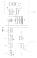
- FIG. 2 illustrates an example structure of a power meter built in the home appliance and an example connection between a control circuit and the power meter.
- the power meter 100 may include a voltage-current measuring unit 110 connected to the external power supply to measure voltages and currents of the external power supply and an electric power calculation circuit 150 configured to calculate the amount of electricity based on the voltages and currents measured by the voltage-current measuring unit so as to output the calculated amount to the control circuit 20.
- the voltage-current measuring unit 110 is directly connected to the external power supply 21 for measuring the voltages and currents of the external power supply 21 that operate the home appliance 10.
- the voltage-current measuring unit 110 includes a voltage measuring part 112 connected with the external power supply 21 in parallel and a current measuring part 114 connected with the external power supply 21 in series.
- the voltage measuring part 112 is connected with the external power supply 21 in parallel and may include two resistances connected in series.
- the current measuring part 114 is connected with the external power supply 21 in series and may include a shunt resistance.
- the values of the voltages and currents measured by the voltage-current measuring unit 110 are transmitted to the electric power calculation circuit 150 and the electric power calculation circuit 150 calculates the amount of the electricity consumed by multiplying the measured voltages and the currents and then multiplying the result by the time.
- the control circuit 20 may include a rectifier 22 configured to rectify the alternating current (AC) power into a direct current (DC) power, a transformer 23 configured to lower the voltage of the direct current power rectified by the rectifier 22, a regulator 26 configured to regulate the voltages of the DC power having passed the transformer 23, and a microcomputer 28 configured to control the operation of the home appliance by using the electric power supplied from the regulator 26.
- a rectifier 22 configured to rectify the alternating current (AC) power into a direct current (DC) power
- a transformer 23 configured to lower the voltage of the direct current power rectified by the rectifier 22
- a regulator 26 configured to regulate the voltages of the DC power having passed the transformer 23
- a microcomputer 28 configured to control the operation of the home appliance by using the electric power supplied from the regulator 26.
- the rectifier 22 rectifies the external power supply that is supplied as sine-wave alternating current power supply and converts the external power into DC power.
- the transformer 23 lowers the voltages of the external power supply 21 into appropriate voltages usable by the microcomputer 28.
- the regulator 26 regulates the voltages of the power having passed the transformer 23 and supplies the regulated DC power to the microcomputer 28.
- the microcomputer 28 is operated by the voltage-lowered DC power and controls the operation of the home appliance 20.
- the microcomputer 28 may control the display 40 to display an operational state of the home appliance 20 and implement a control command input by the user.
- the electric power calculation circuit 150 is connected with the microcomputer 28 and transmits data of the measured electric energy to the microcomputer 28. Also, the electric power calculation circuit 150 may determine whether to measure the amount of the electricity based on the control of the microcomputer 28.
- a device for wired or wireless communication may be connected between the electric power calculation circuit 150 and the microcomputer 28.
- Examples of such a communication device include a UART (Universal Asynchronous Receiver/Transmitter).
- UART Universal Asynchronous Receiver/Transmitter
- the UART is a hardware device configured to automatically perform serial-parallel data conversion necessary for asynchronous communication.
- a photocoupler 160 is disposed before the electric power calculation circuit 150 is connected to the microcomputer 28 via the communication device, to electrically isolate a transmitter and a receiver with respect to a signal.
- the electric power calculation circuit 150 may receive the electricity that passes through the transformer 23 of the control circuit 20.
- the electric energy circulation unit 150 is the circuit configured to calculate the amount of the electricity from the voltage value and the current value input from the voltage-current measuring unit 110.
- the power for operating the electric energy circulation unit 150 can be the electric power having lower voltages, compared with voltages of the external power supply.
- the electric power calculation circuit 150 may be supplied the lowered voltage power, with no auxiliary transformer.
- the control circuit 20 may further include a rectifier circuit 25 connected to the transformer 23 to rectify the power having passed through the transformer.
- the electricity energy calculation circuit 150 is connected to the rectifier circuit 25 to be supplied the rectified electricity.
- the electricity having passed through the transformer 23 is typically rectified via the rectifier 22.
- the rectifier 22 is composed of one rectifier element such as a diode and it flows negative or positive electricity there to perform half wave rectification.
- the rectifier circuit 25 reverses the negative or positive electricity into the other and performs full wave rectification. Also, the rectifier circuit 25 includes a condenser and can smooth out electricity.
- the power meter 100 may further include a regulator 130 connected between the rectifier circuit 25 and the electric power calculation circuit 150 to lower voltages of the electricity having passed through the rectifier circuit 25 into properly lowered voltages.
- the transformer 23 is configured to lower the voltages of the electricity supplied to the microcomputer 28 into properly lowered voltages.
- the voltages of the electricity used for the microcomputer 28 may be different from rated voltages of the electricity used for the electric power calculation circuit 150.
- the regulator 130 may regulate the DC power having the voltages lowered by the rectifier circuit 25 into DC power having more properly lowered voltages.
- the regulator 130 may be a Low Drop-out (LDO) regulator, different from the regulator 26 connected to the microcomputer 28.
- LDO Low Drop-out
- the electricity having 5V lowered by the rectifier circuit 25 is regulated into the electricity having 3.3V that will be supplied to the electric power calculation circuit 150.
- Numeral references of "1" and “2" refer to grounds and a first ground 1 and a second ground 2 are different from each other.
- the external power supply 21 and the electric power calculation circuit 150 are grounded to the first ground 1.
- the regulator 26 and the microcomputer 28 are grounded to the second ground 2.
- the photocoupler 160 is grounded to the first ground 1 and the second ground 2.
- FIG. 3 illustrates an example structure of a power meter built in the home appliance and an example collection between a control circuit and the power meter.
- the electric power calculation circuit 150 is directly connected to the external power supply 21 to be supplied the electricity and a power supply circuit 140 is connected between the external power supply 21 and the electric power calculation circuit 150.
- the electric power calculation circuit 150 may be supplied the electricity via the power supply circuit 140 for the electric power calculation circuit 150 that is directly connected to the external power supply 21.
- the rectifier circuit 25 of FIG. 2 which is disposed between the transformer 23 and the regulator 130 of FIG. 2 , is omitted in FIG. 3 .
- the power supply circuit 140 for the electric power calculation circuit rectifies the external power supply 21 and converts (or lowers) voltages of the external power supply 21 to regulate the external power supply. After that, the regulated external power supply is supplied to the electric power calculation circuit 150.
- Data of the electric energy calculated by the electric power calculation circuit 150 is transmitted to the microcomputer 28 via the photocoupler 160 and a UART.
- the microcomputer 28 of the control circuit 20 controls the display 40 to display the received data on the amount of the electricity, such that the user can be notified of the electricity consumed by the home appliance.
- the display 40 is connected to the wireless communication module 50 such that the user can check the power consumption displayed on the user's smart phone or smart TV or the smart device 70, such as a computer, via the web server 60.
- the user can input a control command of controlling the home appliance via the input unit provided in the display according to a control or operational state of the home appliance displayed on the display 40. Also, the user can command to selectively measure the power consumption of the home appliance or the display to selectively display the measured power consumption.
- the home appliance having the built-in power meter may be a refrigerator, a washing machine, an air conditioner, or a cooking apparatus.
- the power meter may be built in a home appliance having relatively high power consumption. Those electric home appliances mentioned above belong to the home appliances having high power consumption. Accordingly, the power meter may be built in one of those home appliances and can measure the power consumption such that the home appliance can save power.
Landscapes
- Physics & Mathematics (AREA)
- General Physics & Mathematics (AREA)
- Engineering & Computer Science (AREA)
- Power Engineering (AREA)
- Computer Networks & Wireless Communication (AREA)
- Remote Monitoring And Control Of Power-Distribution Networks (AREA)
- Supply And Distribution Of Alternating Current (AREA)
- Control Of Washing Machine And Dryer (AREA)
- Selective Calling Equipment (AREA)
- Cookers (AREA)
Applications Claiming Priority (1)
| Application Number | Priority Date | Filing Date | Title |
|---|---|---|---|
| KR1020120062579A KR101893150B1 (ko) | 2012-06-12 | 2012-06-12 | 전력량측정장치가 내장된 가전기기 |
Publications (3)
| Publication Number | Publication Date |
|---|---|
| EP2674768A2 true EP2674768A2 (fr) | 2013-12-18 |
| EP2674768A3 EP2674768A3 (fr) | 2017-07-05 |
| EP2674768B1 EP2674768B1 (fr) | 2022-08-17 |
Family
ID=48577493
Family Applications (1)
| Application Number | Title | Priority Date | Filing Date |
|---|---|---|---|
| EP13168262.7A Active EP2674768B1 (fr) | 2012-06-12 | 2013-05-17 | Appareil domestique à dispositif de mesure de consommation intégré |
Country Status (4)
| Country | Link |
|---|---|
| US (2) | US9170285B2 (fr) |
| EP (1) | EP2674768B1 (fr) |
| KR (1) | KR101893150B1 (fr) |
| CN (1) | CN103487645B (fr) |
Cited By (2)
| Publication number | Priority date | Publication date | Assignee | Title |
|---|---|---|---|---|
| FR3028619A1 (fr) * | 2014-11-18 | 2016-05-20 | Sagemcom Energy & Telecom Sas | Compteur d'energie electrique comprenant un shunt de mesure |
| WO2019066152A1 (fr) * | 2017-09-29 | 2019-04-04 | (주)코콤 | Dispositif de relais de réseau et procédé de plateforme domotique de gestion d'énergie basée sur l'internet des objets et le nuage |
Families Citing this family (12)
| Publication number | Priority date | Publication date | Assignee | Title |
|---|---|---|---|---|
| KR20140089272A (ko) * | 2013-01-04 | 2014-07-14 | 삼성전자주식회사 | 스마트 장치 및 이를 이용한 홈 네트워크 시스템 |
| KR102173371B1 (ko) * | 2014-01-06 | 2020-11-03 | 엘지전자 주식회사 | 냉장고, 및 홈 어플라이언스 |
| CN105183068B (zh) * | 2015-09-11 | 2017-03-08 | 珠海格力电器股份有限公司 | 家用电器及家用电器控制系统 |
| CN105446296A (zh) * | 2015-12-11 | 2016-03-30 | 四川长虹电器股份有限公司 | 一种检测方法及设备 |
| CN105627520A (zh) * | 2016-01-25 | 2016-06-01 | 四川长虹电器股份有限公司 | 具备远程电量检测的空调及其电量无线检测系统 |
| WO2017161549A1 (fr) * | 2016-03-25 | 2017-09-28 | 程强 | Procédé et système de calcul d'énergie d'ustensile de cuisine en restauration |
| CN105866538A (zh) * | 2016-06-14 | 2016-08-17 | 河北箱变电器有限公司 | 电力系统电量测量仪 |
| CN106028110A (zh) * | 2016-07-13 | 2016-10-12 | 福建捷联电子有限公司 | 具有电源与环境监测功能的液晶电视或显示器 |
| KR20180023375A (ko) * | 2016-08-25 | 2018-03-07 | (주) 이이시스 | 스마트 전원 장치 및 그 제어 방법 |
| KR102587394B1 (ko) * | 2016-11-15 | 2023-10-10 | 일렉트로룩스 어플라이언스 아크티에볼레그 | 가정용 또는 상업용 가전 제품을 위한 모니터링 장치 |
| CN110086148A (zh) * | 2019-05-31 | 2019-08-02 | 深圳市道通智能航空技术有限公司 | 一种电源保护电路及电源 |
| CN114689931A (zh) * | 2020-12-31 | 2022-07-01 | 维谛技术(西安)有限公司 | 一种电量采集电路和装置 |
Family Cites Families (20)
| Publication number | Priority date | Publication date | Assignee | Title |
|---|---|---|---|---|
| JPH09294335A (ja) * | 1996-02-26 | 1997-11-11 | Sanyo Electric Co Ltd | 系統連系発電機 |
| JP2001004665A (ja) * | 1999-06-21 | 2001-01-12 | Toko Seiki Co Ltd | 消費電力計測表示機能付き家庭用電化製品 |
| US6480399B2 (en) * | 2000-03-02 | 2002-11-12 | Power Integrations, Inc. | Switched mode power supply responsive to current derived from voltage across energy transfer element input |
| US7340509B2 (en) * | 2002-07-18 | 2008-03-04 | General Electric Company | Reconfigurable appliance control system |
| KR100484160B1 (ko) * | 2002-09-06 | 2005-04-19 | 삼성전자주식회사 | 소비 전력 표시 장치 |
| JP2009027781A (ja) * | 2007-07-17 | 2009-02-05 | Seiko Epson Corp | 受電制御装置、受電装置、無接点電力伝送システム、充電制御装置、バッテリ装置および電子機器 |
| US7960944B2 (en) * | 2007-09-05 | 2011-06-14 | Eveready Battery Company, Inc. | Power supply that supplies power to and communicates with an electrical appliance |
| US20090088907A1 (en) * | 2007-10-01 | 2009-04-02 | Gridpoint, Inc. | Modular electrical grid interface device |
| WO2009049499A1 (fr) * | 2007-10-17 | 2009-04-23 | Jiasheng Wan | Dispositif de mesure d'énergie électronique modulaire |
| JP2009130987A (ja) * | 2007-11-20 | 2009-06-11 | Panasonic Electric Works Co Ltd | エネルギーマネジメントシステム |
| JP4755229B2 (ja) * | 2008-07-23 | 2011-08-24 | レノボ・シンガポール・プライベート・リミテッド | 電子機器の電力計測システム |
| US8654113B2 (en) * | 2008-09-19 | 2014-02-18 | Mstar Semiconductor, Inc. | Ultra-low-power display control circuit and associated method |
| US8461861B2 (en) * | 2008-11-11 | 2013-06-11 | Bsh Home Appliances Corporation | Energy usage monitor for a household appliance |
| DE102008044378A1 (de) * | 2008-12-05 | 2010-06-10 | BSH Bosch und Siemens Hausgeräte GmbH | Haushaltsgerät mit automatischer Abschaltung |
| JP5612279B2 (ja) | 2009-06-26 | 2014-10-22 | 日本合成化学工業株式会社 | 心筋梗塞非ヒト動物モデル及びその作製方法 |
| KR101144150B1 (ko) * | 2010-02-05 | 2012-05-09 | 유노시스템 주식회사 | 가전기기 및 전자기기의 전력 사용량 측정과 이력 관리 시스템 |
| KR101702838B1 (ko) * | 2010-02-19 | 2017-02-07 | 삼성전자주식회사 | 수요 반응 방법 및 수요 반응 시스템 |
| KR20110099542A (ko) * | 2010-03-02 | 2011-09-08 | 삼성전자주식회사 | 수요 반응 시스템 |
| KR101759932B1 (ko) * | 2010-04-27 | 2017-07-20 | 엘지전자 주식회사 | 전기제품의 소비전력 산정방법 |
| US20110276289A1 (en) * | 2010-05-07 | 2011-11-10 | Samsung Electronics Co., Ltd. | Power monitoring apparatus for household appliance |
-
2012
- 2012-06-12 KR KR1020120062579A patent/KR101893150B1/ko active Active
-
2013
- 2013-05-17 EP EP13168262.7A patent/EP2674768B1/fr active Active
- 2013-05-29 US US13/904,519 patent/US9170285B2/en active Active
- 2013-06-09 CN CN201310231558.6A patent/CN103487645B/zh active Active
-
2015
- 2015-09-23 US US14/862,300 patent/US9797934B2/en not_active Expired - Fee Related
Non-Patent Citations (1)
| Title |
|---|
| None |
Cited By (2)
| Publication number | Priority date | Publication date | Assignee | Title |
|---|---|---|---|---|
| FR3028619A1 (fr) * | 2014-11-18 | 2016-05-20 | Sagemcom Energy & Telecom Sas | Compteur d'energie electrique comprenant un shunt de mesure |
| WO2019066152A1 (fr) * | 2017-09-29 | 2019-04-04 | (주)코콤 | Dispositif de relais de réseau et procédé de plateforme domotique de gestion d'énergie basée sur l'internet des objets et le nuage |
Also Published As
| Publication number | Publication date |
|---|---|
| CN103487645B (zh) | 2016-12-07 |
| KR20130138981A (ko) | 2013-12-20 |
| US9170285B2 (en) | 2015-10-27 |
| CN103487645A (zh) | 2014-01-01 |
| KR101893150B1 (ko) | 2018-08-30 |
| EP2674768B1 (fr) | 2022-08-17 |
| EP2674768A3 (fr) | 2017-07-05 |
| US20160077137A1 (en) | 2016-03-17 |
| US9797934B2 (en) | 2017-10-24 |
| US20130328544A1 (en) | 2013-12-12 |
Similar Documents
| Publication | Publication Date | Title |
|---|---|---|
| US9170285B2 (en) | Home appliance having built-in power meter | |
| KR101828461B1 (ko) | 전기기기, 전력 관리기 및 그 제어 방법 | |
| US10924824B2 (en) | Method for monitoring power consumption based on current sensing, wireless power sensing device and cloud device | |
| EP2903297A1 (fr) | Système pour la surveillance à distance d'appareils électroménagers | |
| EP3125374B1 (fr) | Dispositif de commande de fonctionnement pour appareil électronique | |
| CN107302809B (zh) | 电磁加热烹饪系统及其加热控制装置和控制方法 | |
| US20130178994A1 (en) | Power metering and load control device | |
| CN104159479A (zh) | 在感应加热炊具上操作的无线厨房用具 | |
| EP2955528A1 (fr) | Dispositif de lecture dans le proche infrarouge et ampèremètre | |
| EP2525307A1 (fr) | Système de service après-vente pour appareils domestiques utilisant un réseau intelligent | |
| KR20180103617A (ko) | 스마트 전력 측정 시스템 | |
| JP5555918B2 (ja) | プラグ受 | |
| CN103004054B (zh) | 由低压供电网络为家用电器供电的方法以及适于执行所述方法的家用电器 | |
| CN102998568B (zh) | 一种逆变器电路的性能测试方法及测试装置 | |
| US20120065806A1 (en) | Method for measuring energy usage in an appliance | |
| CN110024251B (zh) | 用于家用或商用电器的监测布置 | |
| KR20140140198A (ko) | 수요반응 기능을 지원하지 않는 전기기기를 위한 수요반응 전력 제어 방법 및 장치 | |
| CN108110553A (zh) | 专用于家用热水器电能计量与远程控制的智能插座 | |
| CN221685688U (zh) | 一种烹饪器具的无线测温电路及烹饪器具 | |
| CN212569083U (zh) | 交流电通断状态的判断电路及智能电器设备 | |
| CN218217693U (zh) | 加热测温电路以及家用电器 | |
| CN214048493U (zh) | 一种控制系统与电磁加热煮茶壶 | |
| CN110736874B (zh) | 一种智能浴霸的电量统计方法 | |
| CN210720565U (zh) | 料理机电路和料理机 | |
| TW200924341A (en) | Dynamic power distribution system |
Legal Events
| Date | Code | Title | Description |
|---|---|---|---|
| PUAI | Public reference made under article 153(3) epc to a published international application that has entered the european phase |
Free format text: ORIGINAL CODE: 0009012 |
|
| 17P | Request for examination filed |
Effective date: 20130605 |
|
| AK | Designated contracting states |
Kind code of ref document: A2 Designated state(s): AL AT BE BG CH CY CZ DE DK EE ES FI FR GB GR HR HU IE IS IT LI LT LU LV MC MK MT NL NO PL PT RO RS SE SI SK SM TR |
|
| AX | Request for extension of the european patent |
Extension state: BA ME |
|
| PUAL | Search report despatched |
Free format text: ORIGINAL CODE: 0009013 |
|
| AK | Designated contracting states |
Kind code of ref document: A3 Designated state(s): AL AT BE BG CH CY CZ DE DK EE ES FI FR GB GR HR HU IE IS IT LI LT LU LV MC MK MT NL NO PL PT RO RS SE SI SK SM TR |
|
| AX | Request for extension of the european patent |
Extension state: BA ME |
|
| RIC1 | Information provided on ipc code assigned before grant |
Ipc: G01R 22/06 20060101ALN20170529BHEP Ipc: G01R 22/10 20060101ALI20170529BHEP Ipc: G01R 22/00 20060101AFI20170529BHEP |
|
| RBV | Designated contracting states (corrected) |
Designated state(s): AL AT BE BG CH CY CZ DE DK EE ES FI FR GB GR HR HU IE IS IT LI LT LU LV MC MK MT NL NO PL PT RO RS SE SI SK SM TR |
|
| STAA | Information on the status of an ep patent application or granted ep patent |
Free format text: STATUS: EXAMINATION IS IN PROGRESS |
|
| 17Q | First examination report despatched |
Effective date: 20210510 |
|
| GRAP | Despatch of communication of intention to grant a patent |
Free format text: ORIGINAL CODE: EPIDOSNIGR1 |
|
| STAA | Information on the status of an ep patent application or granted ep patent |
Free format text: STATUS: GRANT OF PATENT IS INTENDED |
|
| RAP3 | Party data changed (applicant data changed or rights of an application transferred) |
Owner name: LG ELECTRONICS INC. |
|
| INTG | Intention to grant announced |
Effective date: 20220301 |
|
| RAP3 | Party data changed (applicant data changed or rights of an application transferred) |
Owner name: LG ELECTRONICS INC. |
|
| GRAS | Grant fee paid |
Free format text: ORIGINAL CODE: EPIDOSNIGR3 |
|
| GRAA | (expected) grant |
Free format text: ORIGINAL CODE: 0009210 |
|
| STAA | Information on the status of an ep patent application or granted ep patent |
Free format text: STATUS: THE PATENT HAS BEEN GRANTED |
|
| AK | Designated contracting states |
Kind code of ref document: B1 Designated state(s): AL AT BE BG CH CY CZ DE DK EE ES FI FR GB GR HR HU IE IS IT LI LT LU LV MC MK MT NL NO PL PT RO RS SE SI SK SM TR |
|
| REG | Reference to a national code |
Ref country code: GB Ref legal event code: FG4D |
|
| REG | Reference to a national code |
Ref country code: CH Ref legal event code: EP |
|
| REG | Reference to a national code |
Ref country code: DE Ref legal event code: R096 Ref document number: 602013082323 Country of ref document: DE |
|
| REG | Reference to a national code |
Ref country code: IE Ref legal event code: FG4D |
|
| REG | Reference to a national code |
Ref country code: AT Ref legal event code: REF Ref document number: 1512516 Country of ref document: AT Kind code of ref document: T Effective date: 20220915 |
|
| REG | Reference to a national code |
Ref country code: NL Ref legal event code: MP Effective date: 20220817 |
|
| REG | Reference to a national code |
Ref country code: LT Ref legal event code: MG9D |
|
| PG25 | Lapsed in a contracting state [announced via postgrant information from national office to epo] |
Ref country code: SE Free format text: LAPSE BECAUSE OF FAILURE TO SUBMIT A TRANSLATION OF THE DESCRIPTION OR TO PAY THE FEE WITHIN THE PRESCRIBED TIME-LIMIT Effective date: 20220817 Ref country code: RS Free format text: LAPSE BECAUSE OF FAILURE TO SUBMIT A TRANSLATION OF THE DESCRIPTION OR TO PAY THE FEE WITHIN THE PRESCRIBED TIME-LIMIT Effective date: 20220817 Ref country code: PT Free format text: LAPSE BECAUSE OF FAILURE TO SUBMIT A TRANSLATION OF THE DESCRIPTION OR TO PAY THE FEE WITHIN THE PRESCRIBED TIME-LIMIT Effective date: 20221219 Ref country code: NO Free format text: LAPSE BECAUSE OF FAILURE TO SUBMIT A TRANSLATION OF THE DESCRIPTION OR TO PAY THE FEE WITHIN THE PRESCRIBED TIME-LIMIT Effective date: 20221117 Ref country code: NL Free format text: LAPSE BECAUSE OF FAILURE TO SUBMIT A TRANSLATION OF THE DESCRIPTION OR TO PAY THE FEE WITHIN THE PRESCRIBED TIME-LIMIT Effective date: 20220817 Ref country code: LV Free format text: LAPSE BECAUSE OF FAILURE TO SUBMIT A TRANSLATION OF THE DESCRIPTION OR TO PAY THE FEE WITHIN THE PRESCRIBED TIME-LIMIT Effective date: 20220817 Ref country code: LT Free format text: LAPSE BECAUSE OF FAILURE TO SUBMIT A TRANSLATION OF THE DESCRIPTION OR TO PAY THE FEE WITHIN THE PRESCRIBED TIME-LIMIT Effective date: 20220817 Ref country code: FI Free format text: LAPSE BECAUSE OF FAILURE TO SUBMIT A TRANSLATION OF THE DESCRIPTION OR TO PAY THE FEE WITHIN THE PRESCRIBED TIME-LIMIT Effective date: 20220817 Ref country code: ES Free format text: LAPSE BECAUSE OF FAILURE TO SUBMIT A TRANSLATION OF THE DESCRIPTION OR TO PAY THE FEE WITHIN THE PRESCRIBED TIME-LIMIT Effective date: 20220817 |
|
| REG | Reference to a national code |
Ref country code: AT Ref legal event code: MK05 Ref document number: 1512516 Country of ref document: AT Kind code of ref document: T Effective date: 20220817 |
|
| PG25 | Lapsed in a contracting state [announced via postgrant information from national office to epo] |
Ref country code: PL Free format text: LAPSE BECAUSE OF FAILURE TO SUBMIT A TRANSLATION OF THE DESCRIPTION OR TO PAY THE FEE WITHIN THE PRESCRIBED TIME-LIMIT Effective date: 20220817 Ref country code: IS Free format text: LAPSE BECAUSE OF FAILURE TO SUBMIT A TRANSLATION OF THE DESCRIPTION OR TO PAY THE FEE WITHIN THE PRESCRIBED TIME-LIMIT Effective date: 20221217 Ref country code: HR Free format text: LAPSE BECAUSE OF FAILURE TO SUBMIT A TRANSLATION OF THE DESCRIPTION OR TO PAY THE FEE WITHIN THE PRESCRIBED TIME-LIMIT Effective date: 20220817 Ref country code: GR Free format text: LAPSE BECAUSE OF FAILURE TO SUBMIT A TRANSLATION OF THE DESCRIPTION OR TO PAY THE FEE WITHIN THE PRESCRIBED TIME-LIMIT Effective date: 20221118 |
|
| PG25 | Lapsed in a contracting state [announced via postgrant information from national office to epo] |
Ref country code: SM Free format text: LAPSE BECAUSE OF FAILURE TO SUBMIT A TRANSLATION OF THE DESCRIPTION OR TO PAY THE FEE WITHIN THE PRESCRIBED TIME-LIMIT Effective date: 20220817 Ref country code: RO Free format text: LAPSE BECAUSE OF FAILURE TO SUBMIT A TRANSLATION OF THE DESCRIPTION OR TO PAY THE FEE WITHIN THE PRESCRIBED TIME-LIMIT Effective date: 20220817 Ref country code: DK Free format text: LAPSE BECAUSE OF FAILURE TO SUBMIT A TRANSLATION OF THE DESCRIPTION OR TO PAY THE FEE WITHIN THE PRESCRIBED TIME-LIMIT Effective date: 20220817 Ref country code: CZ Free format text: LAPSE BECAUSE OF FAILURE TO SUBMIT A TRANSLATION OF THE DESCRIPTION OR TO PAY THE FEE WITHIN THE PRESCRIBED TIME-LIMIT Effective date: 20220817 Ref country code: AT Free format text: LAPSE BECAUSE OF FAILURE TO SUBMIT A TRANSLATION OF THE DESCRIPTION OR TO PAY THE FEE WITHIN THE PRESCRIBED TIME-LIMIT Effective date: 20220817 |
|
| REG | Reference to a national code |
Ref country code: DE Ref legal event code: R097 Ref document number: 602013082323 Country of ref document: DE |
|
| PG25 | Lapsed in a contracting state [announced via postgrant information from national office to epo] |
Ref country code: SK Free format text: LAPSE BECAUSE OF FAILURE TO SUBMIT A TRANSLATION OF THE DESCRIPTION OR TO PAY THE FEE WITHIN THE PRESCRIBED TIME-LIMIT Effective date: 20220817 Ref country code: EE Free format text: LAPSE BECAUSE OF FAILURE TO SUBMIT A TRANSLATION OF THE DESCRIPTION OR TO PAY THE FEE WITHIN THE PRESCRIBED TIME-LIMIT Effective date: 20220817 |
|
| PLBE | No opposition filed within time limit |
Free format text: ORIGINAL CODE: 0009261 |
|
| STAA | Information on the status of an ep patent application or granted ep patent |
Free format text: STATUS: NO OPPOSITION FILED WITHIN TIME LIMIT |
|
| PG25 | Lapsed in a contracting state [announced via postgrant information from national office to epo] |
Ref country code: AL Free format text: LAPSE BECAUSE OF FAILURE TO SUBMIT A TRANSLATION OF THE DESCRIPTION OR TO PAY THE FEE WITHIN THE PRESCRIBED TIME-LIMIT Effective date: 20220817 |
|
| 26N | No opposition filed |
Effective date: 20230519 |
|
| PG25 | Lapsed in a contracting state [announced via postgrant information from national office to epo] |
Ref country code: SI Free format text: LAPSE BECAUSE OF FAILURE TO SUBMIT A TRANSLATION OF THE DESCRIPTION OR TO PAY THE FEE WITHIN THE PRESCRIBED TIME-LIMIT Effective date: 20220817 |
|
| REG | Reference to a national code |
Ref country code: CH Ref legal event code: PL |
|
| PG25 | Lapsed in a contracting state [announced via postgrant information from national office to epo] |
Ref country code: MC Free format text: LAPSE BECAUSE OF FAILURE TO SUBMIT A TRANSLATION OF THE DESCRIPTION OR TO PAY THE FEE WITHIN THE PRESCRIBED TIME-LIMIT Effective date: 20220817 |
|
| REG | Reference to a national code |
Ref country code: BE Ref legal event code: MM Effective date: 20230531 |
|
| PG25 | Lapsed in a contracting state [announced via postgrant information from national office to epo] |
Ref country code: MC Free format text: LAPSE BECAUSE OF FAILURE TO SUBMIT A TRANSLATION OF THE DESCRIPTION OR TO PAY THE FEE WITHIN THE PRESCRIBED TIME-LIMIT Effective date: 20220817 Ref country code: LU Free format text: LAPSE BECAUSE OF NON-PAYMENT OF DUE FEES Effective date: 20230517 Ref country code: LI Free format text: LAPSE BECAUSE OF NON-PAYMENT OF DUE FEES Effective date: 20230531 Ref country code: CH Free format text: LAPSE BECAUSE OF NON-PAYMENT OF DUE FEES Effective date: 20230531 |
|
| REG | Reference to a national code |
Ref country code: IE Ref legal event code: MM4A |
|
| PG25 | Lapsed in a contracting state [announced via postgrant information from national office to epo] |
Ref country code: IE Free format text: LAPSE BECAUSE OF NON-PAYMENT OF DUE FEES Effective date: 20230517 |
|
| PG25 | Lapsed in a contracting state [announced via postgrant information from national office to epo] |
Ref country code: IE Free format text: LAPSE BECAUSE OF NON-PAYMENT OF DUE FEES Effective date: 20230517 |
|
| PG25 | Lapsed in a contracting state [announced via postgrant information from national office to epo] |
Ref country code: FR Free format text: LAPSE BECAUSE OF NON-PAYMENT OF DUE FEES Effective date: 20230531 Ref country code: BE Free format text: LAPSE BECAUSE OF NON-PAYMENT OF DUE FEES Effective date: 20230531 |
|
| PGFP | Annual fee paid to national office [announced via postgrant information from national office to epo] |
Ref country code: GB Payment date: 20240408 Year of fee payment: 12 |
|
| PGFP | Annual fee paid to national office [announced via postgrant information from national office to epo] |
Ref country code: DE Payment date: 20240405 Year of fee payment: 12 |
|
| PGFP | Annual fee paid to national office [announced via postgrant information from national office to epo] |
Ref country code: IT Payment date: 20240408 Year of fee payment: 12 |
|
| PG25 | Lapsed in a contracting state [announced via postgrant information from national office to epo] |
Ref country code: BG Free format text: LAPSE BECAUSE OF FAILURE TO SUBMIT A TRANSLATION OF THE DESCRIPTION OR TO PAY THE FEE WITHIN THE PRESCRIBED TIME-LIMIT Effective date: 20220817 |
|
| PG25 | Lapsed in a contracting state [announced via postgrant information from national office to epo] |
Ref country code: BG Free format text: LAPSE BECAUSE OF FAILURE TO SUBMIT A TRANSLATION OF THE DESCRIPTION OR TO PAY THE FEE WITHIN THE PRESCRIBED TIME-LIMIT Effective date: 20220817 |
|
| PG25 | Lapsed in a contracting state [announced via postgrant information from national office to epo] |
Ref country code: CY Free format text: LAPSE BECAUSE OF FAILURE TO SUBMIT A TRANSLATION OF THE DESCRIPTION OR TO PAY THE FEE WITHIN THE PRESCRIBED TIME-LIMIT; INVALID AB INITIO Effective date: 20130517 |
|
| PG25 | Lapsed in a contracting state [announced via postgrant information from national office to epo] |
Ref country code: HU Free format text: LAPSE BECAUSE OF FAILURE TO SUBMIT A TRANSLATION OF THE DESCRIPTION OR TO PAY THE FEE WITHIN THE PRESCRIBED TIME-LIMIT; INVALID AB INITIO Effective date: 20130517 |
|
| REG | Reference to a national code |
Ref country code: DE Ref legal event code: R119 Ref document number: 602013082323 Country of ref document: DE |
|
| PG25 | Lapsed in a contracting state [announced via postgrant information from national office to epo] |
Ref country code: TR Free format text: LAPSE BECAUSE OF FAILURE TO SUBMIT A TRANSLATION OF THE DESCRIPTION OR TO PAY THE FEE WITHIN THE PRESCRIBED TIME-LIMIT Effective date: 20220817 |
|
| GBPC | Gb: european patent ceased through non-payment of renewal fee |
Effective date: 20250517 |
|
| PG25 | Lapsed in a contracting state [announced via postgrant information from national office to epo] |
Ref country code: GB Free format text: LAPSE BECAUSE OF NON-PAYMENT OF DUE FEES Effective date: 20250517 |
|
| PG25 | Lapsed in a contracting state [announced via postgrant information from national office to epo] |
Ref country code: DE Free format text: LAPSE BECAUSE OF NON-PAYMENT OF DUE FEES Effective date: 20251202 |
|
| PG25 | Lapsed in a contracting state [announced via postgrant information from national office to epo] |
Ref country code: IT Free format text: LAPSE BECAUSE OF NON-PAYMENT OF DUE FEES Effective date: 20250517 |