EP2683941B1 - Transmission planétaire pour éolienne - Google Patents
Transmission planétaire pour éolienne Download PDFInfo
- Publication number
- EP2683941B1 EP2683941B1 EP12707752.7A EP12707752A EP2683941B1 EP 2683941 B1 EP2683941 B1 EP 2683941B1 EP 12707752 A EP12707752 A EP 12707752A EP 2683941 B1 EP2683941 B1 EP 2683941B1
- Authority
- EP
- European Patent Office
- Prior art keywords
- outer ring
- planet gear
- planetary transmission
- bore
- radial projection
- Prior art date
- Legal status (The legal status is an assumption and is not a legal conclusion. Google has not performed a legal analysis and makes no representation as to the accuracy of the status listed.)
- Not-in-force
Links
Images


Classifications
-
- F—MECHANICAL ENGINEERING; LIGHTING; HEATING; WEAPONS; BLASTING
- F03—MACHINES OR ENGINES FOR LIQUIDS; WIND, SPRING, OR WEIGHT MOTORS; PRODUCING MECHANICAL POWER OR A REACTIVE PROPULSIVE THRUST, NOT OTHERWISE PROVIDED FOR
- F03D—WIND MOTORS
- F03D15/00—Transmission of mechanical power
-
- F—MECHANICAL ENGINEERING; LIGHTING; HEATING; WEAPONS; BLASTING
- F03—MACHINES OR ENGINES FOR LIQUIDS; WIND, SPRING, OR WEIGHT MOTORS; PRODUCING MECHANICAL POWER OR A REACTIVE PROPULSIVE THRUST, NOT OTHERWISE PROVIDED FOR
- F03D—WIND MOTORS
- F03D15/00—Transmission of mechanical power
- F03D15/10—Transmission of mechanical power using gearing not limited to rotary motion, e.g. with oscillating or reciprocating members
-
- F—MECHANICAL ENGINEERING; LIGHTING; HEATING; WEAPONS; BLASTING
- F03—MACHINES OR ENGINES FOR LIQUIDS; WIND, SPRING, OR WEIGHT MOTORS; PRODUCING MECHANICAL POWER OR A REACTIVE PROPULSIVE THRUST, NOT OTHERWISE PROVIDED FOR
- F03D—WIND MOTORS
- F03D80/00—Details, components or accessories not provided for in groups F03D1/00 - F03D17/00
- F03D80/70—Bearing or lubricating arrangements
-
- F—MECHANICAL ENGINEERING; LIGHTING; HEATING; WEAPONS; BLASTING
- F16—ENGINEERING ELEMENTS AND UNITS; GENERAL MEASURES FOR PRODUCING AND MAINTAINING EFFECTIVE FUNCTIONING OF MACHINES OR INSTALLATIONS; THERMAL INSULATION IN GENERAL
- F16C—SHAFTS; FLEXIBLE SHAFTS; ELEMENTS OR CRANKSHAFT MECHANISMS; ROTARY BODIES OTHER THAN GEARING ELEMENTS; BEARINGS
- F16C35/00—Rigid support of bearing units; Housings, e.g. caps, covers
- F16C35/04—Rigid support of bearing units; Housings, e.g. caps, covers in the case of ball or roller bearings
- F16C35/06—Mounting or dismounting of ball or roller bearings; Fixing them onto shaft or in housing
- F16C35/067—Fixing them in a housing
-
- F—MECHANICAL ENGINEERING; LIGHTING; HEATING; WEAPONS; BLASTING
- F05—INDEXING SCHEMES RELATING TO ENGINES OR PUMPS IN VARIOUS SUBCLASSES OF CLASSES F01-F04
- F05B—INDEXING SCHEME RELATING TO WIND, SPRING, WEIGHT, INERTIA OR LIKE MOTORS, TO MACHINES OR ENGINES FOR LIQUIDS COVERED BY SUBCLASSES F03B, F03D AND F03G
- F05B2240/00—Components
- F05B2240/50—Bearings
- F05B2240/54—Radial bearings
-
- F—MECHANICAL ENGINEERING; LIGHTING; HEATING; WEAPONS; BLASTING
- F05—INDEXING SCHEMES RELATING TO ENGINES OR PUMPS IN VARIOUS SUBCLASSES OF CLASSES F01-F04
- F05B—INDEXING SCHEME RELATING TO WIND, SPRING, WEIGHT, INERTIA OR LIKE MOTORS, TO MACHINES OR ENGINES FOR LIQUIDS COVERED BY SUBCLASSES F03B, F03D AND F03G
- F05B2250/00—Geometry
- F05B2250/20—Geometry three-dimensional
- F05B2250/23—Geometry three-dimensional prismatic
- F05B2250/232—Geometry three-dimensional prismatic conical
-
- F—MECHANICAL ENGINEERING; LIGHTING; HEATING; WEAPONS; BLASTING
- F05—INDEXING SCHEMES RELATING TO ENGINES OR PUMPS IN VARIOUS SUBCLASSES OF CLASSES F01-F04
- F05B—INDEXING SCHEME RELATING TO WIND, SPRING, WEIGHT, INERTIA OR LIKE MOTORS, TO MACHINES OR ENGINES FOR LIQUIDS COVERED BY SUBCLASSES F03B, F03D AND F03G
- F05B2260/00—Function
- F05B2260/30—Retaining components in desired mutual position
-
- F—MECHANICAL ENGINEERING; LIGHTING; HEATING; WEAPONS; BLASTING
- F05—INDEXING SCHEMES RELATING TO ENGINES OR PUMPS IN VARIOUS SUBCLASSES OF CLASSES F01-F04
- F05B—INDEXING SCHEME RELATING TO WIND, SPRING, WEIGHT, INERTIA OR LIKE MOTORS, TO MACHINES OR ENGINES FOR LIQUIDS COVERED BY SUBCLASSES F03B, F03D AND F03G
- F05B2260/00—Function
- F05B2260/40—Transmission of power
- F05B2260/403—Transmission of power through the shape of the drive components
- F05B2260/4031—Transmission of power through the shape of the drive components as in toothed gearing
- F05B2260/40311—Transmission of power through the shape of the drive components as in toothed gearing of the epicyclic, planetary or differential type
-
- F—MECHANICAL ENGINEERING; LIGHTING; HEATING; WEAPONS; BLASTING
- F16—ENGINEERING ELEMENTS AND UNITS; GENERAL MEASURES FOR PRODUCING AND MAINTAINING EFFECTIVE FUNCTIONING OF MACHINES OR INSTALLATIONS; THERMAL INSULATION IN GENERAL
- F16C—SHAFTS; FLEXIBLE SHAFTS; ELEMENTS OR CRANKSHAFT MECHANISMS; ROTARY BODIES OTHER THAN GEARING ELEMENTS; BEARINGS
- F16C19/00—Bearings with rolling contact, for exclusively rotary movement
- F16C19/22—Bearings with rolling contact, for exclusively rotary movement with bearing rollers essentially of the same size in one or more circular rows, e.g. needle bearings
- F16C19/24—Bearings with rolling contact, for exclusively rotary movement with bearing rollers essentially of the same size in one or more circular rows, e.g. needle bearings for radial load mainly
- F16C19/26—Bearings with rolling contact, for exclusively rotary movement with bearing rollers essentially of the same size in one or more circular rows, e.g. needle bearings for radial load mainly with a single row of rollers
-
- F—MECHANICAL ENGINEERING; LIGHTING; HEATING; WEAPONS; BLASTING
- F16—ENGINEERING ELEMENTS AND UNITS; GENERAL MEASURES FOR PRODUCING AND MAINTAINING EFFECTIVE FUNCTIONING OF MACHINES OR INSTALLATIONS; THERMAL INSULATION IN GENERAL
- F16C—SHAFTS; FLEXIBLE SHAFTS; ELEMENTS OR CRANKSHAFT MECHANISMS; ROTARY BODIES OTHER THAN GEARING ELEMENTS; BEARINGS
- F16C19/00—Bearings with rolling contact, for exclusively rotary movement
- F16C19/22—Bearings with rolling contact, for exclusively rotary movement with bearing rollers essentially of the same size in one or more circular rows, e.g. needle bearings
- F16C19/34—Bearings with rolling contact, for exclusively rotary movement with bearing rollers essentially of the same size in one or more circular rows, e.g. needle bearings for both radial and axial load
- F16C19/36—Bearings with rolling contact, for exclusively rotary movement with bearing rollers essentially of the same size in one or more circular rows, e.g. needle bearings for both radial and axial load with a single row of rollers
- F16C19/364—Bearings with rolling contact, for exclusively rotary movement with bearing rollers essentially of the same size in one or more circular rows, e.g. needle bearings for both radial and axial load with a single row of rollers with tapered rollers, i.e. rollers having essentially the shape of a truncated cone
-
- F—MECHANICAL ENGINEERING; LIGHTING; HEATING; WEAPONS; BLASTING
- F16—ENGINEERING ELEMENTS AND UNITS; GENERAL MEASURES FOR PRODUCING AND MAINTAINING EFFECTIVE FUNCTIONING OF MACHINES OR INSTALLATIONS; THERMAL INSULATION IN GENERAL
- F16C—SHAFTS; FLEXIBLE SHAFTS; ELEMENTS OR CRANKSHAFT MECHANISMS; ROTARY BODIES OTHER THAN GEARING ELEMENTS; BEARINGS
- F16C19/00—Bearings with rolling contact, for exclusively rotary movement
- F16C19/54—Systems consisting of a plurality of bearings with rolling friction
- F16C19/541—Systems consisting of juxtaposed rolling bearings including at least one angular contact bearing
- F16C19/542—Systems consisting of juxtaposed rolling bearings including at least one angular contact bearing with two rolling bearings with angular contact
- F16C19/543—Systems consisting of juxtaposed rolling bearings including at least one angular contact bearing with two rolling bearings with angular contact in O-arrangement
-
- F—MECHANICAL ENGINEERING; LIGHTING; HEATING; WEAPONS; BLASTING
- F16—ENGINEERING ELEMENTS AND UNITS; GENERAL MEASURES FOR PRODUCING AND MAINTAINING EFFECTIVE FUNCTIONING OF MACHINES OR INSTALLATIONS; THERMAL INSULATION IN GENERAL
- F16C—SHAFTS; FLEXIBLE SHAFTS; ELEMENTS OR CRANKSHAFT MECHANISMS; ROTARY BODIES OTHER THAN GEARING ELEMENTS; BEARINGS
- F16C2300/00—Application independent of particular apparatuses
- F16C2300/10—Application independent of particular apparatuses related to size
- F16C2300/14—Large applications, e.g. bearings having an inner diameter exceeding 500 mm
-
- F—MECHANICAL ENGINEERING; LIGHTING; HEATING; WEAPONS; BLASTING
- F16—ENGINEERING ELEMENTS AND UNITS; GENERAL MEASURES FOR PRODUCING AND MAINTAINING EFFECTIVE FUNCTIONING OF MACHINES OR INSTALLATIONS; THERMAL INSULATION IN GENERAL
- F16C—SHAFTS; FLEXIBLE SHAFTS; ELEMENTS OR CRANKSHAFT MECHANISMS; ROTARY BODIES OTHER THAN GEARING ELEMENTS; BEARINGS
- F16C2360/00—Engines or pumps
- F16C2360/31—Wind motors
-
- F—MECHANICAL ENGINEERING; LIGHTING; HEATING; WEAPONS; BLASTING
- F16—ENGINEERING ELEMENTS AND UNITS; GENERAL MEASURES FOR PRODUCING AND MAINTAINING EFFECTIVE FUNCTIONING OF MACHINES OR INSTALLATIONS; THERMAL INSULATION IN GENERAL
- F16C—SHAFTS; FLEXIBLE SHAFTS; ELEMENTS OR CRANKSHAFT MECHANISMS; ROTARY BODIES OTHER THAN GEARING ELEMENTS; BEARINGS
- F16C2361/00—Apparatus or articles in engineering in general
- F16C2361/61—Toothed gear systems, e.g. support of pinion shafts
-
- F—MECHANICAL ENGINEERING; LIGHTING; HEATING; WEAPONS; BLASTING
- F16—ENGINEERING ELEMENTS AND UNITS; GENERAL MEASURES FOR PRODUCING AND MAINTAINING EFFECTIVE FUNCTIONING OF MACHINES OR INSTALLATIONS; THERMAL INSULATION IN GENERAL
- F16H—GEARING
- F16H57/00—General details of gearing
- F16H57/08—General details of gearing of gearings with members having orbital motion
- F16H2057/085—Bearings for orbital gears
-
- Y—GENERAL TAGGING OF NEW TECHNOLOGICAL DEVELOPMENTS; GENERAL TAGGING OF CROSS-SECTIONAL TECHNOLOGIES SPANNING OVER SEVERAL SECTIONS OF THE IPC; TECHNICAL SUBJECTS COVERED BY FORMER USPC CROSS-REFERENCE ART COLLECTIONS [XRACs] AND DIGESTS
- Y02—TECHNOLOGIES OR APPLICATIONS FOR MITIGATION OR ADAPTATION AGAINST CLIMATE CHANGE
- Y02E—REDUCTION OF GREENHOUSE GAS [GHG] EMISSIONS, RELATED TO ENERGY GENERATION, TRANSMISSION OR DISTRIBUTION
- Y02E10/00—Energy generation through renewable energy sources
- Y02E10/70—Wind energy
- Y02E10/72—Wind turbines with rotation axis in wind direction
Definitions
- the invention relates to a planetary gear of a wind turbine and a wind turbine. Furthermore, the invention relates to a rolling bearing assembly of a planetary gear of a wind turbine.
- WO 02/079644 A1 From the WO 02/079644 A1 is a wind turbine with a planetary gear known, the planetary gears, which are rotatably supported by means of a bearing on an axis.
- the gears of the planetary gear used are partly rotatably supported by means of rolling bearings.
- the planet wheels of a planetary gear used in wind turbines are rotatably supported by a bearing having a plurality of axially adjacent juxtaposed outer rings.
- the outer rings are arranged in a bore of the planetary gear and rotatably connected by a press fit with the planet gear.
- the outer rings are secured against axial displacement by means of a spring ring, which is arranged between adjacent outer rings and engages in a radial groove in the planetary gear.
- the problems caused by the wandering of the outer rings can be avoided, for example, by omitting the outer rings and the spring ring and by forming the rolling element raceways and the starting rims in one piece with the planetary gear.
- a design makes minimum demands on the material composition of the planetary gear, at least in the area of the rolling body raceways.
- a comparatively complex machining of the planetary gear is usually required in order to form a suitable geometry of the rolling body raceways and the starting rims and a suitable surface finish. Slightly lower, the requirements and cost can be maintained if you keep the outer rings and only replaced the spring ring by a one-piece with the planetary spacer ring.
- the object of the invention is to prevent or at least limit damage caused by migrating outer rings during storage of a planetary gear of a planetary gear of a wind turbine.
- the planetary gear of a wind turbine has a ring gear with an internal toothing and at least one planet gear with an external toothing, which is in engagement with the internal toothing of the ring gear on.
- the planet gear is rotatably mounted on an axle by means of a bearing.
- the bearing has at least one outer ring with a radially outwardly projecting radial projection and at least one set of rolling elements which roll on the outer ring, on.
- the planet gear has a bore and in the region of an axial end a recess which radially expands the bore.
- the outer ring is arranged in the bore of the planetary gear such that the radial projection of the outer ring engages in the recess of the planetary gear.
- the invention has the advantage that it considerably reduces the risk of damage from migrating outer rings in a planetary gear with comparatively little effort.
- the recess of the planetary gear may be formed in particular as a step.
- the outer ring may be attached to the planetary gear.
- the outer ring can be non-rotatably connected by means of press fit with the planetary gear. This can reduce the damage caused by migration of the outer ring damage.
- the radial projection of the outer ring may be formed integrally with the outer ring. This allows a particularly favorable ratio between size and mechanical stability.
- the radial projection of the outer ring may be arranged in the region of an axial end of the outer ring and / or axially abut the planetary gear.
- the radial projection of the outer ring can terminate axially flush with the planet or be set back axially relative to the axial end of the planetary gear.
- This embodiment has the advantage that it requires no additional space in the axial direction compared to a conventional outer ring without a radial projection.
- the outer ring may have a cylindrical seat surface which bears in contact with the planet wheel in the area of the bore and the radial projection of the outer ring can project radially outwards beyond the seat surface.
- outer ring On the outer ring several sets of rolling elements can roll axially next to each other. Furthermore, a plurality of outer rings can be arranged axially next to one another.
- the bearing may have at least one inner ring, which is arranged on the axis and in particular rotatably connected to the axis. Furthermore, the inner ring can abut axially on a carrier.
- the invention further relates to a wind turbine with an inventively designed planetary gear.
- the rolling bearing assembly comprises a planetary gear with external teeth and a bearing that the planetary gear rotatable on an axis stores.
- the bearing has at least one outer ring with a radially outwardly projecting radial projection and at least one set of rolling elements which roll on the outer ring, on.
- the planet gear has a bore and in the region of an axial end a recess which radially expands the bore.
- the outer ring is arranged in the bore of the planetary gear such that the radial projection of the outer ring engages in the recess of the planetary gear.
- FIG. 1 shows an embodiment of a planetary gear according to the invention of a wind turbine with an inventively designed roller bearing assembly in a sectional view.
- the planetary gear has a housing 1, which can be anchored by bolts 2 fixed to the wind turbine. Furthermore, the planetary gear on a support 3, which is rotatably supported by means of a bearing 4 in the housing 1 and is equipped at one axial end with a coupling 5. At this axial end, a rotor shaft, not shown figuratively introduced into the carrier 3 and rotatably connected by means of the clutch 5 to the carrier 3.
- the carrier 3 carries a plurality, for example three, formed as planetary gears 6 gears with external teeth.
- the planet gears 6 are each mounted rotatably by means of a bearing 7 on an axis 8 which is rotatably connected to the carrier 3.
- the planetary gears 6 are arranged within a ring gear 9 with internal teeth, wherein the external toothing of the planetary gears 6 is in each case with the internal toothing of the ring gear 9 in engagement.
- the ring gear 9 is rotatably connected to the housing 1.
- the planetary gears surround a gear formed as a sun gear 10 with external teeth such that the planetary gears 6 engage with their external teeth respectively in the outer toothing of the sun gear 10.
- the sun gear 10 may be non-rotatably connected to a non-illustrated generator shaft or a non-figuratively shown further gear stage.
- a rotary feedthrough 11 is arranged within the sun gear 10.
- FIG. 2 shows an embodiment of the rolling bearing assembly according to the invention of FIG. 1 illustrated planetary gear according to the invention in a sectional view.
- two inner rings 12 are arranged at a distance axially adjacent to each other on the axis 8 and axially abut respectively on the carrier 3.
- the inner rings 12 have cylindrical seats 13 which can rest under prestress on the axle 8, so that the inner rings 12 are non-rotatably connected by means of press fit with the axis 8.
- Each inner ring 12 has a cylindrical WälzMechterrorismbahn 14, which is axially bounded on both sides by a stop board 15.
- the planet gear 6 has a bore 16, which has in each case a radial extension in the form of a step 17 or another recess to both axial ends of the planetary gear 6.
- two outer rings 18 are arranged axially adjacent to each other at a distance.
- the outer rings 18 have cylindrical seats 19 which can rest in the bore 16 under bias on the planet gear 6, so that the outer rings 18 are non-rotatably connected by means of press fit with the planet gear 6.
- Each outer ring 18 has a cylindrical WälzSystemterrorismbahn 20, which is axially bounded on a side which is oriented toward the axial center of the bore 16 through a stop board 21. On the other hand, no inrun 21 is provided.
- a radial projection 22 is formed, which projects radially outward beyond the seat surface 19 of the outer ring 18 and radially overlaps with the planet gear 6.
- the radial projection 22 of the outer ring 18 engages in the step 17 of the planetary gear 6 and strikes axially in the region of the stage 17 on the planet gear 6 at.
- the stage 17 of the planetary gear 6 and the radial projection 22 may be coordinated so that the radial projection 22 terminates axially flush with the planet gear 6.
- the radial projection 22 is set back axially relative to the axial end of the planetary gear 6.
- FIG. 2 shown two axially juxtaposed sets of cylindrical rolling elements 23 which roll on the WälzConsequentlymaschinebahnen 14 of the inner rings 12 and the WälzConsequentlymaschinebahnen 20 of the outer rings 18. Accordingly, the planet gear 6 is mounted in the illustrated embodiment by means of two axially juxtaposed cylindrical roller bearings.
- FIG. 2 illustrated rolling bearing assembly is held together by a movement of the inner rings 12 out of the bore 16 out by the axial abutment of the inner rings 12 to the support 3 is prevented.
- About the out of the bore 16 out starting ribs 15 of the inner rings 12, on the rolling elements 23 and the Anlaufborde 21 of the outer rings 18 thus a movement of the outer rings 18 is prevented from the bore 16 out.
- a movement the outer rings 18 deeper into the bore 16 is prevented by the axial abutment of the radial projections 22 of the outer rings 18 to the planet gear 6.
- Over the thrust rims 21 of the outer rings 18, over the rolling elements 23 and over the out of the bore 16 oriented outboard 15 of the inner rings 12 thus a movement of the inner rings 12 deeper into the bore 16 is prevented.
- the radial projections 22 of the outer rings 18 thus have the consequence that other measures for axial securing of the outer rings 18, such as partially embedded in radial grooves spring rings, can be omitted.
- Such spring rings can be worn in an application in wind turbines over time, although at least expected for a cylindrical roller bearing for this application low axial forces.
- the radial projections 22 have a much longer service life, since they are relatively solid and made of a very high quality material and with high surface quality.
- chips would not occur in the middle of the rolling bearing arrangement but only in peripheral areas, so that there is less likelihood of damage to the bearing 7.
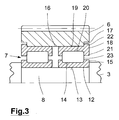
- FIG. 3 shows a further embodiment of the rolling bearing assembly of the invention in FIG. 1 illustrated planetary gear according to the invention in a sectional view.
- FIG. 3 illustrated embodiment differs in terms of the formation of the inner rings 12 and the outer rings 18 of FIG. 2 ,
- the inner rings 12 according to FIG. 3 in each case only one inrun board 15.
- This inrun 15 is oriented relative to the bore 16 in each case to the outside.
- the outer rings 18 include FIG. 3 in contrast to FIG. 2 not just one, but two start-up rims 21, which are respectively arranged on both sides of the WälzSystemterrorismen 20 of the outer rings 18. Otherwise, this corresponds to FIG. 3 illustrated embodiment of the FIG. 2 ,
- FIG. 4 shows a further embodiment of the rolling bearing assembly of the invention in FIG. 1 illustrated planetary gear according to the invention in a sectional view.
- FIG. 4 illustrated embodiment differs in terms of the formation of the inner rings 12 and the outer rings 18 and the rolling elements 23 of the Figures 2 and 3 .
- the inner rings 12 and the outer rings 18 according to FIG. 4 no cylindrical but tapered rolling element raceways 14, 20 on.
- the rolling elements 23 are not cylindrical, but conical.
- the inner rings 12 are otherwise analogous to FIG. 2 trained and accordingly each have a starting board 15 on both sides of the rolling element raceways 14.
- the outer rings 18 have no thrust walls 21, but with respect to the radial projection 22 analogous to the Figures 2 and 3 educated.
- one or more inner rings 12 and / or one or more outer rings 18 may each be formed multi-row, d. H. Have rolling element raceways 14, 20 for a plurality of axially juxtaposed sets of rolling elements 23.
- the rolling bearing assembly may have two double-row inner rings 12 and two double-row outer rings 18.
- a single row and a double row inner ring 12 and a single row and a double row outer ring 18 or other combinations may be provided. In this case, combinations are possible in which a multi-row inner ring 12 is combined with a plurality of single-row outer rings 18 or vice versa. The combination of differently multi-row inner rings 12 and outer rings 18 is possible.
- axially adjacent inner rings 12 and / or axially adjacent outer rings 18 can each be axially held by a spacer ring at a distance. This spacer ring is not fixed axially on the axis 8 or on the planet gear 6 in the rule.
- the inner rings 12 and the outer rings 18 may each be made of a high grade steel for rolling bearing applications.
- the thrust rims 15 may be formed integrally with the inner rings 12.
- the thrust rims 21 may be integrally formed with the outer rings 18.
- the radial projections 22 may be formed integrally with the outer rings 18.
- the diameter of the bore 16 of the planetary gear 6 may be greater than 300 mm outside the steps 17 and in particular have values between 300 mm and 450 mm.
Landscapes
- Engineering & Computer Science (AREA)
- General Engineering & Computer Science (AREA)
- Mechanical Engineering (AREA)
- Life Sciences & Earth Sciences (AREA)
- Sustainable Development (AREA)
- Sustainable Energy (AREA)
- Chemical & Material Sciences (AREA)
- Combustion & Propulsion (AREA)
- Rolling Contact Bearings (AREA)
- Retarders (AREA)
Claims (11)
- Transmission planétaire pour éolienne, comprenant une couronne dentée (9), qui présente une denture intérieure et au moins un pignon satellite (6) qui présente une denture extérieure qui est en prise avec la denture intérieure de la couronne dentée (9),- le pignon satellite (6) étant supporté à rotation sur un axe (8) au moyen d'un support sur palier (7),caractérisée en ce que- le support sur palier (7) présente au moins une bague extérieure (18) avec une saillie radiale (22) faisant saillie radialement vers l'extérieur, et au moins un jeu de corps de roulement (23) qui roulent sur la bague extérieure (18),- le pignon satellite (6) présente un alésage (16) et, dans la région d'une extrémité axiale, un évidement (17) qui élargit radialement l'alésage (16), et- la bague extérieure (18) est disposée dans l'alésage (16) du pignon satellite (6) de telle sorte que la saillie radiale (22) de la bague extérieure (18) vienne en prise dans l'évidement (17) du pignon satellite (6).
- Transmission planétaire selon la revendication 1, dans laquelle la bague extérieure (18) est fixée sur le pignon satellite (6).
- Transmission planétaire selon l'une quelconque des revendications précédentes, dans laquelle la saillie radiale (22) de la bague extérieure (18) est réalisée d'une seule pièce avec la bague extérieure (18).
- Transmission planétaire selon l'une quelconque des revendications précédentes, dans laquelle la saillie radiale (22) de la bague extérieure (18) est disposée dans la région d'une extrémité axiale de la bague extérieure (18).
- Transmission planétaire selon l'une quelconque des revendications précédentes, dans laquelle la saillie radiale (22) de la bague extérieure (18) bute axialement contre le pignon satellite (6).
- Transmission planétaire selon l'une quelconque des revendications précédentes, dans laquelle la saillie radiale (22) de la bague extérieure (18) se termine axialement en affleurement avec le pignon satellite (6) ou est en retrait axialement par rapport à l'extrémité axiale du pignon satellite (6).
- Transmission planétaire selon l'une quelconque des revendications précédentes, dans laquelle la bague extérieure (18) présente une surface de siège cylindrique (19) qui s'applique dans la région de l'alésage (16) en contact avec le pignon satellite (6) et la saillie radiale (22) de la bague extérieure (18) fait saillie radialement vers l'extérieur au-delà de la surface de siège (19).
- Transmission planétaire selon l'une quelconque des revendications précédentes, dans laquelle plusieurs jeux de corps de roulement (23) roulent axialement les uns à côté des autres sur la bague extérieure (18).
- Transmission planétaire selon l'une quelconque des revendications précédentes, dans laquelle plusieurs bagues extérieures (18) sont disposées axialement les unes à côté des autres.
- Éolienne comprenant une transmission planétaire selon l'une quelconque des revendications précédentes.
- Agencement de palier à roulement d'une transmission planétaire d'une éolienne, comprenant- un pignon satellite (6) qui présente une denture extérieure et- un support sur palier (7) qui supporte le pignon satellite (6) de manière à pouvoir tourner sur un axe (8),caractérisé en ce que- le support sur palier (7) présente au moins une bague extérieure (18) avec une saillie radiale (22) faisant saillie radialement vers l'extérieur et au moins un jeu de corps de roulement (23) qui roulent sur la bague extérieure (18),- le pignon satellite (6) présente un alésage (16) et, dans la région d'une extrémité axiale, un évidement (17) qui élargit radialement l'alésage (16), et- la bague extérieure (18) est disposée dans l'alésage (16) du pignon satellite (6) de telle sorte que la saillie radiale (22) de la bague extérieure (18) vienne en prise dans l'évidement (17) du pignon satellite (6).
Applications Claiming Priority (2)
| Application Number | Priority Date | Filing Date | Title |
|---|---|---|---|
| DE201110005240 DE102011005240A1 (de) | 2011-03-08 | 2011-03-08 | Wälzlageranordnung einer Windkraftanlage |
| PCT/EP2012/053806 WO2012120005A1 (fr) | 2011-03-08 | 2012-03-06 | Différentiel planétaire d'une éolienne |
Publications (2)
| Publication Number | Publication Date |
|---|---|
| EP2683941A1 EP2683941A1 (fr) | 2014-01-15 |
| EP2683941B1 true EP2683941B1 (fr) | 2015-05-13 |
Family
ID=45811496
Family Applications (1)
| Application Number | Title | Priority Date | Filing Date |
|---|---|---|---|
| EP12707752.7A Not-in-force EP2683941B1 (fr) | 2011-03-08 | 2012-03-06 | Transmission planétaire pour éolienne |
Country Status (6)
| Country | Link |
|---|---|
| US (1) | US9086056B2 (fr) |
| EP (1) | EP2683941B1 (fr) |
| CN (1) | CN103415700A (fr) |
| DE (1) | DE102011005240A1 (fr) |
| ES (1) | ES2544836T3 (fr) |
| WO (1) | WO2012120005A1 (fr) |
Families Citing this family (8)
| Publication number | Priority date | Publication date | Assignee | Title |
|---|---|---|---|---|
| DE102011088481A1 (de) * | 2011-12-05 | 2013-06-27 | Schaeffler Technologies AG & Co. KG | Kombination aus Lager und Anschlusskonstruktion |
| CN104214211A (zh) * | 2014-08-21 | 2014-12-17 | 沈阳罕王精密轴承有限公司 | 一种外圈带齿轮的双列圆柱、圆锥滚子组合轴承 |
| US9777797B2 (en) | 2014-12-01 | 2017-10-03 | Asmo Co., Ltd. | Actuator |
| DE102015200463B4 (de) * | 2015-01-14 | 2017-02-02 | Schaeffler Technologies AG & Co. KG | Planetenradlagerung mit axial und radial abgestützter Hülse |
| DE102016205530A1 (de) * | 2016-04-04 | 2017-10-05 | Zf Friedrichshafen Ag | Lageranordnung |
| DE102016004343A1 (de) * | 2016-04-13 | 2017-10-19 | Senvion Gmbh | Windenergieanlage mit einem Triebstrang |
| EP3406941B1 (fr) * | 2017-05-24 | 2020-07-15 | Flender GmbH | Dispositif de roue cylindrique, transmission et éolienne |
| CN112728012A (zh) * | 2019-10-14 | 2021-04-30 | 廖安国 | 行星轮系一体化结构 |
Family Cites Families (18)
| Publication number | Priority date | Publication date | Assignee | Title |
|---|---|---|---|---|
| DE8803124U1 (de) * | 1988-03-08 | 1988-04-21 | Ludwig, Alfons, 8151 Sachsenkam | Radial-Zylinderrollenlager |
| JP2804295B2 (ja) * | 1989-06-09 | 1998-09-24 | ジャトコ株式会社 | 遊星歯車装置のキャリア組立体 |
| US5219232A (en) * | 1991-11-27 | 1993-06-15 | Tiodize Company, Inc. | Floating bushing roller bearing |
| US5368528A (en) * | 1993-04-01 | 1994-11-29 | General Motors Corporation | Bearing thrust assembly for planet gears in planetary gear carrier assemblies |
| DE20005227U1 (de) * | 2000-03-20 | 2000-08-03 | Skf Gmbh, 97421 Schweinfurt | Lageranordnung |
| DK174085B1 (da) * | 2001-04-02 | 2002-06-03 | Vestas Wind Sys As | Vindmølle med planetgear |
| DE10141667A1 (de) * | 2001-08-25 | 2003-03-13 | Aloys Wobben | Vorrichtung zum Verdrehen von zwei Bauteilen gegeneinander |
| WO2003029671A1 (fr) * | 2001-10-03 | 2003-04-10 | Vestas Wind Systems A/S | Appareil permettant de lubrifier les roulements d'un generateur d'electricite dans une eolienne |
| JP2003172345A (ja) * | 2001-12-07 | 2003-06-20 | Koyo Seiko Co Ltd | 車軸ピニオン用軸受装置および車両用終減速装置 |
| DE10235287A1 (de) * | 2002-08-02 | 2004-02-12 | Ab Skf | Lageranordnung |
| DE10260132A1 (de) * | 2002-12-19 | 2004-07-01 | Winergy Ag | Planetengetriebe für eine Windkraftanlage |
| DE102004062117B4 (de) * | 2004-12-23 | 2006-11-30 | Ab Skf | Lageranordnung für einen Computertomographen |
| DE102005049185B4 (de) * | 2005-10-14 | 2012-02-09 | Ab Skf | Anordnung zur Lagerung eines Planetenrades eines Planetengetriebes |
| DE102006012598B4 (de) * | 2006-03-18 | 2010-10-07 | Zf Lenksysteme Gmbh | Wälzlager |
| DE102006051817A1 (de) | 2006-11-03 | 2008-05-08 | Schaeffler Kg | Lageranordnung zur drehbaren Lagerung eines Planetenrades auf einem Planetenträger |
| US8062165B2 (en) * | 2008-01-25 | 2011-11-22 | GM Global Technology Operations LLC | Bearing assembly for planetary gear pinion |
| CN201521627U (zh) * | 2009-09-28 | 2010-07-07 | 南车戚墅堰机车车辆工艺研究所有限公司 | 行星齿轮轴向定位装置 |
| CA2694130C (fr) * | 2010-02-12 | 2013-04-16 | Mitsubishi Heavy Industries, Ltd. | Boite de vitesse pour eolienne et generateur eolien |
-
2011
- 2011-03-08 DE DE201110005240 patent/DE102011005240A1/de not_active Ceased
-
2012
- 2012-03-06 ES ES12707752.7T patent/ES2544836T3/es active Active
- 2012-03-06 EP EP12707752.7A patent/EP2683941B1/fr not_active Not-in-force
- 2012-03-06 US US14/003,661 patent/US9086056B2/en not_active Expired - Fee Related
- 2012-03-06 WO PCT/EP2012/053806 patent/WO2012120005A1/fr not_active Ceased
- 2012-03-06 CN CN2012800117207A patent/CN103415700A/zh active Pending
Also Published As
| Publication number | Publication date |
|---|---|
| ES2544836T3 (es) | 2015-09-04 |
| DE102011005240A1 (de) | 2012-09-13 |
| EP2683941A1 (fr) | 2014-01-15 |
| CN103415700A (zh) | 2013-11-27 |
| US9086056B2 (en) | 2015-07-21 |
| US20140066245A1 (en) | 2014-03-06 |
| WO2012120005A1 (fr) | 2012-09-13 |
Similar Documents
| Publication | Publication Date | Title |
|---|---|---|
| EP2683941B1 (fr) | Transmission planétaire pour éolienne | |
| EP2185815B1 (fr) | Palier de rotor pour une éolienne | |
| EP3351830B2 (fr) | Engrenage planétaire comprenant un palier de porte-satellites amélioré | |
| EP2954233B1 (fr) | Palier de satellite dans un train planétaire | |
| EP2948688A1 (fr) | Roulement à rouleaux cylindriques | |
| WO2009030220A2 (fr) | Palier de rotor pour une éolienne | |
| EP3406941B1 (fr) | Dispositif de roue cylindrique, transmission et éolienne | |
| EP2951434A1 (fr) | Transmission d'éolienne | |
| EP2679867A1 (fr) | Engrenage planétaire | |
| EP3222863A1 (fr) | Ensemble de palier | |
| EP3404294B1 (fr) | Engrenage, en particulier pour générateurs éoliens | |
| EP2703693B1 (fr) | Support épicycloïdal | |
| DE102012210169A1 (de) | Exzentergetriebe | |
| AT518787B1 (de) | Zahnradanordnung | |
| WO2018177946A1 (fr) | Ensemble palier à roulement et éolienne | |
| DE102015207642A1 (de) | Aktor mit Planetenwälzgewindetrieb | |
| EP3230622B1 (fr) | Arbre de roue planétaire monté de façon articulée | |
| DE102014223472A1 (de) | Schwenkmotorgetriebe für ein Wankstabilisierungssystem | |
| DE102007055362A1 (de) | Wälzlager für ein wellenförmiges Bauteil | |
| DE102020116588A1 (de) | Schräggleitlager | |
| EP4416402B1 (fr) | Ensemble palier principal pour éolienne | |
| DE102011083090A1 (de) | Planetenlagerung und Windenergieanlagengetriebe | |
| DE102017221528A1 (de) | Getriebe für eine Windkraftanlage oder einen Stellantrieb | |
| EP2598762A1 (fr) | Ensemble palier et transmission | |
| DE102008022187A1 (de) | Lageranordnung zur drehbaren Lagerung eines Planetenrades auf einem Planetenträger |
Legal Events
| Date | Code | Title | Description |
|---|---|---|---|
| PUAI | Public reference made under article 153(3) epc to a published international application that has entered the european phase |
Free format text: ORIGINAL CODE: 0009012 |
|
| 17P | Request for examination filed |
Effective date: 20130701 |
|
| AK | Designated contracting states |
Kind code of ref document: A1 Designated state(s): AL AT BE BG CH CY CZ DE DK EE ES FI FR GB GR HR HU IE IS IT LI LT LU LV MC MK MT NL NO PL PT RO RS SE SI SK SM TR |
|
| DAX | Request for extension of the european patent (deleted) | ||
| GRAP | Despatch of communication of intention to grant a patent |
Free format text: ORIGINAL CODE: EPIDOSNIGR1 |
|
| INTG | Intention to grant announced |
Effective date: 20140926 |
|
| GRAS | Grant fee paid |
Free format text: ORIGINAL CODE: EPIDOSNIGR3 |
|
| GRAA | (expected) grant |
Free format text: ORIGINAL CODE: 0009210 |
|
| AK | Designated contracting states |
Kind code of ref document: B1 Designated state(s): AL AT BE BG CH CY CZ DE DK EE ES FI FR GB GR HR HU IE IS IT LI LT LU LV MC MK MT NL NO PL PT RO RS SE SI SK SM TR |
|
| REG | Reference to a national code |
Ref country code: GB Ref legal event code: FG4D Free format text: NOT ENGLISH |
|
| REG | Reference to a national code |
Ref country code: CH Ref legal event code: EP |
|
| REG | Reference to a national code |
Ref country code: IE Ref legal event code: FG4D Free format text: LANGUAGE OF EP DOCUMENT: GERMAN |
|
| REG | Reference to a national code |
Ref country code: AT Ref legal event code: REF Ref document number: 726965 Country of ref document: AT Kind code of ref document: T Effective date: 20150615 |
|
| REG | Reference to a national code |
Ref country code: DE Ref legal event code: R096 Ref document number: 502012003127 Country of ref document: DE Effective date: 20150625 |
|
| REG | Reference to a national code |
Ref country code: ES Ref legal event code: FG2A Ref document number: 2544836 Country of ref document: ES Kind code of ref document: T3 Effective date: 20150904 |
|
| REG | Reference to a national code |
Ref country code: NL Ref legal event code: MP Effective date: 20150513 |
|
| REG | Reference to a national code |
Ref country code: LT Ref legal event code: MG4D |
|
| PG25 | Lapsed in a contracting state [announced via postgrant information from national office to epo] |
Ref country code: HR Free format text: LAPSE BECAUSE OF FAILURE TO SUBMIT A TRANSLATION OF THE DESCRIPTION OR TO PAY THE FEE WITHIN THE PRESCRIBED TIME-LIMIT Effective date: 20150513 Ref country code: LT Free format text: LAPSE BECAUSE OF FAILURE TO SUBMIT A TRANSLATION OF THE DESCRIPTION OR TO PAY THE FEE WITHIN THE PRESCRIBED TIME-LIMIT Effective date: 20150513 Ref country code: FI Free format text: LAPSE BECAUSE OF FAILURE TO SUBMIT A TRANSLATION OF THE DESCRIPTION OR TO PAY THE FEE WITHIN THE PRESCRIBED TIME-LIMIT Effective date: 20150513 Ref country code: PT Free format text: LAPSE BECAUSE OF FAILURE TO SUBMIT A TRANSLATION OF THE DESCRIPTION OR TO PAY THE FEE WITHIN THE PRESCRIBED TIME-LIMIT Effective date: 20150914 Ref country code: NO Free format text: LAPSE BECAUSE OF FAILURE TO SUBMIT A TRANSLATION OF THE DESCRIPTION OR TO PAY THE FEE WITHIN THE PRESCRIBED TIME-LIMIT Effective date: 20150813 |
|
| PG25 | Lapsed in a contracting state [announced via postgrant information from national office to epo] |
Ref country code: RS Free format text: LAPSE BECAUSE OF FAILURE TO SUBMIT A TRANSLATION OF THE DESCRIPTION OR TO PAY THE FEE WITHIN THE PRESCRIBED TIME-LIMIT Effective date: 20150513 Ref country code: BG Free format text: LAPSE BECAUSE OF FAILURE TO SUBMIT A TRANSLATION OF THE DESCRIPTION OR TO PAY THE FEE WITHIN THE PRESCRIBED TIME-LIMIT Effective date: 20150813 Ref country code: LV Free format text: LAPSE BECAUSE OF FAILURE TO SUBMIT A TRANSLATION OF THE DESCRIPTION OR TO PAY THE FEE WITHIN THE PRESCRIBED TIME-LIMIT Effective date: 20150513 Ref country code: IS Free format text: LAPSE BECAUSE OF FAILURE TO SUBMIT A TRANSLATION OF THE DESCRIPTION OR TO PAY THE FEE WITHIN THE PRESCRIBED TIME-LIMIT Effective date: 20150913 Ref country code: GR Free format text: LAPSE BECAUSE OF FAILURE TO SUBMIT A TRANSLATION OF THE DESCRIPTION OR TO PAY THE FEE WITHIN THE PRESCRIBED TIME-LIMIT Effective date: 20150814 |
|
| PG25 | Lapsed in a contracting state [announced via postgrant information from national office to epo] |
Ref country code: EE Free format text: LAPSE BECAUSE OF FAILURE TO SUBMIT A TRANSLATION OF THE DESCRIPTION OR TO PAY THE FEE WITHIN THE PRESCRIBED TIME-LIMIT Effective date: 20150513 Ref country code: DK Free format text: LAPSE BECAUSE OF FAILURE TO SUBMIT A TRANSLATION OF THE DESCRIPTION OR TO PAY THE FEE WITHIN THE PRESCRIBED TIME-LIMIT Effective date: 20150513 |
|
| REG | Reference to a national code |
Ref country code: DE Ref legal event code: R097 Ref document number: 502012003127 Country of ref document: DE |
|
| PG25 | Lapsed in a contracting state [announced via postgrant information from national office to epo] |
Ref country code: SK Free format text: LAPSE BECAUSE OF FAILURE TO SUBMIT A TRANSLATION OF THE DESCRIPTION OR TO PAY THE FEE WITHIN THE PRESCRIBED TIME-LIMIT Effective date: 20150513 Ref country code: RO Free format text: LAPSE BECAUSE OF NON-PAYMENT OF DUE FEES Effective date: 20150513 Ref country code: CZ Free format text: LAPSE BECAUSE OF FAILURE TO SUBMIT A TRANSLATION OF THE DESCRIPTION OR TO PAY THE FEE WITHIN THE PRESCRIBED TIME-LIMIT Effective date: 20150513 Ref country code: PL Free format text: LAPSE BECAUSE OF FAILURE TO SUBMIT A TRANSLATION OF THE DESCRIPTION OR TO PAY THE FEE WITHIN THE PRESCRIBED TIME-LIMIT Effective date: 20150513 |
|
| PLBE | No opposition filed within time limit |
Free format text: ORIGINAL CODE: 0009261 |
|
| STAA | Information on the status of an ep patent application or granted ep patent |
Free format text: STATUS: NO OPPOSITION FILED WITHIN TIME LIMIT |
|
| 26N | No opposition filed |
Effective date: 20160216 |
|
| PG25 | Lapsed in a contracting state [announced via postgrant information from national office to epo] |
Ref country code: IT Free format text: LAPSE BECAUSE OF FAILURE TO SUBMIT A TRANSLATION OF THE DESCRIPTION OR TO PAY THE FEE WITHIN THE PRESCRIBED TIME-LIMIT Effective date: 20150513 |
|
| PG25 | Lapsed in a contracting state [announced via postgrant information from national office to epo] |
Ref country code: SI Free format text: LAPSE BECAUSE OF FAILURE TO SUBMIT A TRANSLATION OF THE DESCRIPTION OR TO PAY THE FEE WITHIN THE PRESCRIBED TIME-LIMIT Effective date: 20150513 |
|
| PGFP | Annual fee paid to national office [announced via postgrant information from national office to epo] |
Ref country code: BE Payment date: 20160324 Year of fee payment: 5 |
|
| PGFP | Annual fee paid to national office [announced via postgrant information from national office to epo] |
Ref country code: ES Payment date: 20160422 Year of fee payment: 5 |
|
| REG | Reference to a national code |
Ref country code: DE Ref legal event code: R119 Ref document number: 502012003127 Country of ref document: DE |
|
| PG25 | Lapsed in a contracting state [announced via postgrant information from national office to epo] |
Ref country code: LU Free format text: LAPSE BECAUSE OF FAILURE TO SUBMIT A TRANSLATION OF THE DESCRIPTION OR TO PAY THE FEE WITHIN THE PRESCRIBED TIME-LIMIT Effective date: 20160306 Ref country code: MC Free format text: LAPSE BECAUSE OF FAILURE TO SUBMIT A TRANSLATION OF THE DESCRIPTION OR TO PAY THE FEE WITHIN THE PRESCRIBED TIME-LIMIT Effective date: 20150513 |
|
| REG | Reference to a national code |
Ref country code: CH Ref legal event code: PL |
|
| GBPC | Gb: european patent ceased through non-payment of renewal fee |
Effective date: 20160306 |
|
| REG | Reference to a national code |
Ref country code: IE Ref legal event code: MM4A |
|
| REG | Reference to a national code |
Ref country code: FR Ref legal event code: ST Effective date: 20161130 |
|
| PG25 | Lapsed in a contracting state [announced via postgrant information from national office to epo] |
Ref country code: FR Free format text: LAPSE BECAUSE OF NON-PAYMENT OF DUE FEES Effective date: 20160331 Ref country code: IE Free format text: LAPSE BECAUSE OF NON-PAYMENT OF DUE FEES Effective date: 20160306 Ref country code: CH Free format text: LAPSE BECAUSE OF NON-PAYMENT OF DUE FEES Effective date: 20160331 Ref country code: DE Free format text: LAPSE BECAUSE OF NON-PAYMENT OF DUE FEES Effective date: 20161001 Ref country code: GB Free format text: LAPSE BECAUSE OF NON-PAYMENT OF DUE FEES Effective date: 20160306 Ref country code: LI Free format text: LAPSE BECAUSE OF NON-PAYMENT OF DUE FEES Effective date: 20160331 |
|
| PG25 | Lapsed in a contracting state [announced via postgrant information from national office to epo] |
Ref country code: NL Free format text: LAPSE BECAUSE OF FAILURE TO SUBMIT A TRANSLATION OF THE DESCRIPTION OR TO PAY THE FEE WITHIN THE PRESCRIBED TIME-LIMIT Effective date: 20150513 Ref country code: SE Free format text: LAPSE BECAUSE OF FAILURE TO SUBMIT A TRANSLATION OF THE DESCRIPTION OR TO PAY THE FEE WITHIN THE PRESCRIBED TIME-LIMIT Effective date: 20150513 |
|
| PG25 | Lapsed in a contracting state [announced via postgrant information from national office to epo] |
Ref country code: MT Free format text: LAPSE BECAUSE OF FAILURE TO SUBMIT A TRANSLATION OF THE DESCRIPTION OR TO PAY THE FEE WITHIN THE PRESCRIBED TIME-LIMIT Effective date: 20150513 |
|
| REG | Reference to a national code |
Ref country code: BE Ref legal event code: MM Effective date: 20170331 |
|
| REG | Reference to a national code |
Ref country code: AT Ref legal event code: MM01 Ref document number: 726965 Country of ref document: AT Kind code of ref document: T Effective date: 20170306 |
|
| PG25 | Lapsed in a contracting state [announced via postgrant information from national office to epo] |
Ref country code: BE Free format text: LAPSE BECAUSE OF NON-PAYMENT OF DUE FEES Effective date: 20170331 Ref country code: SM Free format text: LAPSE BECAUSE OF FAILURE TO SUBMIT A TRANSLATION OF THE DESCRIPTION OR TO PAY THE FEE WITHIN THE PRESCRIBED TIME-LIMIT Effective date: 20150513 Ref country code: HU Free format text: LAPSE BECAUSE OF FAILURE TO SUBMIT A TRANSLATION OF THE DESCRIPTION OR TO PAY THE FEE WITHIN THE PRESCRIBED TIME-LIMIT; INVALID AB INITIO Effective date: 20120306 Ref country code: CY Free format text: LAPSE BECAUSE OF FAILURE TO SUBMIT A TRANSLATION OF THE DESCRIPTION OR TO PAY THE FEE WITHIN THE PRESCRIBED TIME-LIMIT Effective date: 20150513 |
|
| PG25 | Lapsed in a contracting state [announced via postgrant information from national office to epo] |
Ref country code: MK Free format text: LAPSE BECAUSE OF FAILURE TO SUBMIT A TRANSLATION OF THE DESCRIPTION OR TO PAY THE FEE WITHIN THE PRESCRIBED TIME-LIMIT Effective date: 20150513 Ref country code: TR Free format text: LAPSE BECAUSE OF FAILURE TO SUBMIT A TRANSLATION OF THE DESCRIPTION OR TO PAY THE FEE WITHIN THE PRESCRIBED TIME-LIMIT Effective date: 20150513 |
|
| REG | Reference to a national code |
Ref country code: ES Ref legal event code: FD2A Effective date: 20180629 |
|
| PG25 | Lapsed in a contracting state [announced via postgrant information from national office to epo] |
Ref country code: ES Free format text: LAPSE BECAUSE OF NON-PAYMENT OF DUE FEES Effective date: 20170307 |
|
| PG25 | Lapsed in a contracting state [announced via postgrant information from national office to epo] |
Ref country code: AT Free format text: LAPSE BECAUSE OF NON-PAYMENT OF DUE FEES Effective date: 20170306 |
|
| PG25 | Lapsed in a contracting state [announced via postgrant information from national office to epo] |
Ref country code: AL Free format text: LAPSE BECAUSE OF FAILURE TO SUBMIT A TRANSLATION OF THE DESCRIPTION OR TO PAY THE FEE WITHIN THE PRESCRIBED TIME-LIMIT Effective date: 20150513 |