EP2691701B2 - Procédé d'optimisation de la combustion totale des gaz d'échappement d'une installation de combustion - Google Patents
Procédé d'optimisation de la combustion totale des gaz d'échappement d'une installation de combustion Download PDFInfo
- Publication number
- EP2691701B2 EP2691701B2 EP12712955.9A EP12712955A EP2691701B2 EP 2691701 B2 EP2691701 B2 EP 2691701B2 EP 12712955 A EP12712955 A EP 12712955A EP 2691701 B2 EP2691701 B2 EP 2691701B2
- Authority
- EP
- European Patent Office
- Prior art keywords
- combustion
- nozzle
- primary
- fluid
- gases
- Prior art date
- Legal status (The legal status is an assumption and is not a legal conclusion. Google has not performed a legal analysis and makes no representation as to the accuracy of the status listed.)
- Active
Links
Images
Classifications
-
- F—MECHANICAL ENGINEERING; LIGHTING; HEATING; WEAPONS; BLASTING
- F23—COMBUSTION APPARATUS; COMBUSTION PROCESSES
- F23G—CREMATION FURNACES; CONSUMING WASTE PRODUCTS BY COMBUSTION
- F23G5/00—Incineration of waste; Incinerator constructions; Details, accessories or control therefor
- F23G5/08—Incineration of waste; Incinerator constructions; Details, accessories or control therefor having supplementary heating
- F23G5/14—Incineration of waste; Incinerator constructions; Details, accessories or control therefor having supplementary heating including secondary combustion
- F23G5/16—Incineration of waste; Incinerator constructions; Details, accessories or control therefor having supplementary heating including secondary combustion in a separate combustion chamber
-
- F—MECHANICAL ENGINEERING; LIGHTING; HEATING; WEAPONS; BLASTING
- F23—COMBUSTION APPARATUS; COMBUSTION PROCESSES
- F23L—SUPPLYING AIR OR NON-COMBUSTIBLE LIQUIDS OR GASES TO COMBUSTION APPARATUS IN GENERAL ; VALVES OR DAMPERS SPECIALLY ADAPTED FOR CONTROLLING AIR SUPPLY OR DRAUGHT IN COMBUSTION APPARATUS; INDUCING DRAUGHT IN COMBUSTION APPARATUS; TOPS FOR CHIMNEYS OR VENTILATING SHAFTS; TERMINALS FOR FLUES
- F23L9/00—Passages or apertures for delivering secondary air for completing combustion of fuel
-
- F—MECHANICAL ENGINEERING; LIGHTING; HEATING; WEAPONS; BLASTING
- F23—COMBUSTION APPARATUS; COMBUSTION PROCESSES
- F23G—CREMATION FURNACES; CONSUMING WASTE PRODUCTS BY COMBUSTION
- F23G5/00—Incineration of waste; Incinerator constructions; Details, accessories or control therefor
- F23G5/08—Incineration of waste; Incinerator constructions; Details, accessories or control therefor having supplementary heating
- F23G5/14—Incineration of waste; Incinerator constructions; Details, accessories or control therefor having supplementary heating including secondary combustion
- F23G5/16—Incineration of waste; Incinerator constructions; Details, accessories or control therefor having supplementary heating including secondary combustion in a separate combustion chamber
- F23G5/165—Incineration of waste; Incinerator constructions; Details, accessories or control therefor having supplementary heating including secondary combustion in a separate combustion chamber arranged at a different level
-
- F—MECHANICAL ENGINEERING; LIGHTING; HEATING; WEAPONS; BLASTING
- F23—COMBUSTION APPARATUS; COMBUSTION PROCESSES
- F23L—SUPPLYING AIR OR NON-COMBUSTIBLE LIQUIDS OR GASES TO COMBUSTION APPARATUS IN GENERAL ; VALVES OR DAMPERS SPECIALLY ADAPTED FOR CONTROLLING AIR SUPPLY OR DRAUGHT IN COMBUSTION APPARATUS; INDUCING DRAUGHT IN COMBUSTION APPARATUS; TOPS FOR CHIMNEYS OR VENTILATING SHAFTS; TERMINALS FOR FLUES
- F23L7/00—Supplying non-combustible liquids or gases, other than air, to the fire, e.g. oxygen, steam
-
- F—MECHANICAL ENGINEERING; LIGHTING; HEATING; WEAPONS; BLASTING
- F23—COMBUSTION APPARATUS; COMBUSTION PROCESSES
- F23L—SUPPLYING AIR OR NON-COMBUSTIBLE LIQUIDS OR GASES TO COMBUSTION APPARATUS IN GENERAL ; VALVES OR DAMPERS SPECIALLY ADAPTED FOR CONTROLLING AIR SUPPLY OR DRAUGHT IN COMBUSTION APPARATUS; INDUCING DRAUGHT IN COMBUSTION APPARATUS; TOPS FOR CHIMNEYS OR VENTILATING SHAFTS; TERMINALS FOR FLUES
- F23L9/00—Passages or apertures for delivering secondary air for completing combustion of fuel
- F23L9/02—Passages or apertures for delivering secondary air for completing combustion of fuel by discharging the air above the fire
-
- F—MECHANICAL ENGINEERING; LIGHTING; HEATING; WEAPONS; BLASTING
- F23—COMBUSTION APPARATUS; COMBUSTION PROCESSES
- F23L—SUPPLYING AIR OR NON-COMBUSTIBLE LIQUIDS OR GASES TO COMBUSTION APPARATUS IN GENERAL ; VALVES OR DAMPERS SPECIALLY ADAPTED FOR CONTROLLING AIR SUPPLY OR DRAUGHT IN COMBUSTION APPARATUS; INDUCING DRAUGHT IN COMBUSTION APPARATUS; TOPS FOR CHIMNEYS OR VENTILATING SHAFTS; TERMINALS FOR FLUES
- F23L2900/00—Special arrangements for supplying or treating air or oxidant for combustion; Injecting inert gas, water or steam into the combustion chamber
- F23L2900/07002—Injecting inert gas, other than steam or evaporated water, into the combustion chambers
Definitions
- the present invention relates to a method for optimizing the burnout of exhaust gases from an incineration plant according to the preamble of claim 1.
- a method for optimizing the burnout of exhaust gases from an incineration plant is described, for example, in EPA-1508745 described.
- Incineration plants for burning solid fuels such as municipal waste, substitute fuels, biomass and other materials are well known to those skilled in the art.
- Such systems include a combustion chamber in which the solid is burned with the supply of primary air, which is referred to as primary combustion.
- the solid goes through various sub-processes from the inlet into the combustion chamber to the outlet, which can be roughly divided into drying, ignition, combustion and ash burnout.
- exhaust gases of different composition are generated. While in the drying phase the primary air only absorbs moisture from the solid to be burned, pyrolytic decomposition products are found in the ignition phase. In contrast to the drying phase, the oxygen supplied in the ignition phase is often completely converted, so that the exhaust gas stream generated in this phase contains very little or no oxygen. In the combustion phase, exhaust gases with typical compositions of CO, CO 2 , O 2 , H 2 O and N 2 are produced, while practically unused air is present above the ash burnout.
- these different exhaust gas streams reach an afterburning chamber arranged downstream in the direction of flow, where they are burned out with the supply of secondary air, which is referred to as secondary combustion.
- a process comprising combustion of the solid and afterburning of the incompletely burned exhaust gas components is, for example, from WO 2007/090510 known, which aims to break down the primary nitrogen compounds NH 3 and HCN in order to minimize the formation of nitrogen oxides (NO x ) in the afterburning chamber.
- EP-A-1077077 concerns a similar procedure to that of WO2007/090510 , whereby the SNCR process is used to denitrify the flue gases, in which no catalyst is used, but a reducing agent is injected into the flue gases.
- Such SNCR processes work at temperatures of 850 to 1000°C and require sophisticated control.
- the reduction of nitrogen oxides is also... WO 99/58902 thematised.
- the gases emerging from the combustion chamber are homogenized with the addition of an oxygen-free or oxygen-poor medium in a mixing stage, after which the homogenized exhaust gas stream passes through a steady-state zone in which the nitrogen oxides that have already formed are to be reduced.
- the amount of pyrolysis gas produced is so large that the locally available amount of secondary air is not sufficient for complete burnout. This causes unburned gases to escape from the afterburning chamber, which is reflected, for example, in CO peaks in the chimney.
- the peripheral wall surrounding the combustion chamber or the afterburning chamber can be damaged by the prevailing high temperatures.
- caking or coking can occur in this area, which must be removed in complex maintenance work.
- the temperature in the inlet area of the combustion chamber should be reduced by injecting water drops or water vapor.
- the aim of the present invention is therefore to provide a method for optimizing the burnout of exhaust gases from an incineration system, which, on the one hand, ensures a high level of operational safety and, on the other hand, allows a high level of operational safety Energy recovery from combustion.
- the method according to the invention therefore includes the steps that the solid to be burned is introduced via an inlet into a combustion chamber defining a primary combustion chamber, the solid is burned in the primary combustion chamber in the form of a combustion bed conveyed via a combustion grate with the supply of primary air and the burned solid is burned via a is discharged from the primary combustion chamber at the outlet located opposite the inlet in the conveying direction.
- the primary combustion gases released during the combustion of the solid are burned in an after-combustion chamber which defines a secondary combustion chamber and is arranged downstream in the direction of flow, i.e. generally above the combustion chamber, with the supply of secondary air.
- the exhaust gases containing the primary combustion gases are homogenized in a mixing zone. This is done using a fluid introduced via a nozzle.
- a nozzle
- nozzle is to be understood as an indefinite article; The term therefore includes both a single nozzle and several nozzles.
- homogenization means that the exhaust gases or the individual exhaust gas streams of different compositions are mixed in such a way that a gas mixture that is as homogeneous as possible is obtained.
- the mixing zone now adjoins the combustion bed at least approximately directly in the direction of flow of the exhaust gases. In other words, it is generally arranged at least approximately directly above the combustion bed. This makes it possible to mix very hot exhaust gas streams, such as those that can arise in the ignition or combustion zone, practically immediately above the combustion bed with the cooler exhaust gas streams from the drying and ash burnout zone and thus compensate for or reduce temperature peaks at an early stage. At the same time, the process allows the energy recovery balance to not be impaired, as would be the case with cooling using a cooling medium.
- the homogenization of the exhaust gas streams generated in the individual combustion zones results in a gas mixture that is optimally preconditioned for afterburning in the secondary combustion chamber.
- the present invention makes it possible to ensure optimal combustion of the exhaust gases even with a low (secondary) excess of air;
- the emission of pollutants, such as CO or unburned hydrocarbons, can therefore be kept very low, even with small amounts of secondary air supplied.
- the mixture of the reduced nitrogen-containing combustion gases (nitrogen oxide precursor substances) generated in the combustion zone with the oxygen present above the drying or burnout zone does not result in an increase in nitrogen oxides. This can be explained by the fact that in the course of mixing the exhaust gas stream from the combustion zone with the oxygen-rich exhaust gas streams occurring in the drying and burnout zone, its temperature is simultaneously reduced, which prevents the formation of thermal NO x .
- the fluid is introduced via one or more nozzles.
- the exit velocity of the fluid from the nozzle is approximately 40 to approximately 120 m/s, with the nozzle in the sense of the present invention being aligned at an angle of -10° to +10° relative to the inclination of the combustion grate, so that in the Mixing zone, the primary combustion gases from a drying and ash burnout zone are mixed with the primary combustion gases from an ignition and combustion zone.
- nozzles In addition to the nozzles defined above, there may be other nozzles that are not aligned at the angle defined above relative to the inclination of the combustion grate.
- the inclination of the combustion grate is understood to mean the total inclination of the grate (and not the orientation of any individual grate levels that may be present).
- the orientation of the nozzle according to the invention ensures that, even when the mixing zone is arranged according to the invention directly above the combustion bed, excessive whirling up of solids from the grate is avoided.
- the fluid injection speed of approximately 40 to approximately 120 m/s according to the invention also contributes to avoiding the whirling up of solids.
- the combination found of the nozzle arrangement according to the invention and the injection speed thus makes it possible overall to connect the mixing zone at least approximately directly to the combustion bed in the direction of flow of the exhaust gases, without excessive, undesirable whirling of the solids from the combustion grate.
- a MACH number of 1 is equivalent to the speed of sound, which is usually given as 343 m/s for air at 20°C and reaches even higher values at higher temperatures, such as those found in combustion chambers.
- the distance between the mixing zone and the fuel bed can be a maximum of 1.5 meters, preferably a maximum of 0.8 meters. This distance therefore refers to the maximum distance between the upper limit of the combustion bed and the beginning of the mixing zone in the direction of flow of the exhaust gases.
- the mixing zone is spaced accordingly from the combustion grate. Furthermore, the mixing zone can extend at most to a distance of 2 meters measured from the combustion bed. Viewed in the direction of flow of the exhaust gases, the mixing zone ends after a maximum of 2 meters and thus at a sufficient distance before the secondary air injection. In the case of the mixing zone, according to the invention, which adjoins the combustion bed at least approximately directly, the upper limit mentioned is sufficient to obtain the desired homogenization of the exhaust gases.
- the exit velocity of the fluid from the nozzle is approximately 90 m/s.
- the exit speed refers to the speed at which the fluid exits the nozzle opening.
- the nozzles used as standard usually have a circular nozzle cross section of 60 mm to 200 mm. It is conceivable that the nozzle cross section tapers steadily towards the nozzle mouth, so that the diameter of the nozzle outlet opening is 60 mm to 90 mm.
- the respective nozzle is preferably aligned at an angle of -10° to +5°, more preferably from -5° to +5°, relative to the inclination of the combustion grate.
- the respective nozzle can be aligned at an angle of -10° to 0° relative to the inclination of the combustion grate.
- the fluid comprises a flue gas returned from a zone downstream of the secondary combustion chamber. In conventionally designed waste incineration plants, the return preferably takes place from a zone between the steam generator and the chimney.
- the amount of flue gas introduced is approximately 5 to 35% of the amount of primary air supplied, preferably approximately 20%.
- any other conceivable fluid can be used, in particular air, an inert gas such as nitrogen, water vapor or mixtures thereof.
- the fluid is injected according to a preferred embodiment via a nozzle or row of nozzles arranged in this area. This means that a very pronounced temperature imbalance and thus damage or contamination of the peripheral wall surrounding the combustion chamber can be effectively prevented.
- the respective nozzle preferably has an outer tube and an inner tube running in the axial direction of the outer tube and enclosed by it, the inner tube being intended to guide the flue gas and the outer tube to guide air .
- the inside diameter of the inner tube is approximately 70 mm
- the inside diameter of the outer tube i.e. the outside diameter of the annular gap between the inner tube and the outer tube, is approximately 110 mm.
- the air flow serves as a shield that protects the nozzle from the accumulation of contaminants carried in the flue gas. Especially at the temperatures present in the inlet area, such deposits could easily lead to caking, which in extreme cases could lead to nozzle failure; This is effectively prevented according to the described embodiment.
- a combustion chamber of an incineration system for carrying out the method can have a peripheral wall surrounding a primary combustion chamber, an inlet for introducing the solid to be burned into the primary combustion chamber, a combustion grate for combustion of the solid, an outlet arranged opposite the inlet in the conveying direction of the solid for discharging the burned solid from the primary combustion chamber and a nozzle for homogenizing the exhaust gases containing the primary combustion gases released during combustion.
- the nozzle is arranged in an area of at most 3 meters, preferably 0.5 meters to 3 meters, most preferably 0.5 to 2 meters above the combustion grate.
- the nozzle is arranged in the peripheral wall of the combustion chamber, preferably in the area of the inlet or the outlet.
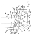
- the solid 2 to be burned is filled into a filling funnel 4 and from there, usually by means of a metering plunger, is introduced into the combustion chamber 8 via an inlet 6.
- the combustion chamber 8 comprises a peripheral wall 10 which encloses a primary combustion chamber 12 which tapers towards the top.
- the solid 2 is conveyed in the form of a combustion bed 14 via a (feed) combustion grate 16 through which primary air flows and is burned in the process.
- a drying zone In the conveying direction F, there are successively a drying zone, an ignition zone, a combustion zone and an ash burnout zone before the burned solid is discharged via an outlet 18 arranged opposite the inlet 6 and is subsequently fed to a slag conveyor via a slag remover.
- the primary air is distributed via individual underwind chambers 20a, 20b, 20c, 20d, which are fed via separate primary air lines 22a, 22b, 22c, 22d.
- Nozzles 24a, 24b, 24c indicated by arrows are arranged, via which a fluid is introduced into the combustion chamber 8.
- the nozzles are designed in such a way that the exit velocity of the fluid from the nozzles is 40 to 120 m/s.
- a nozzle 24a is arranged in the inlet-side region 8' of the combustion chamber 8, specifically in a part 10' of the peripheral wall 10 that faces the inlet and runs obliquely upwards.
- Two nozzles 24b, 24c are arranged in the outlet-side region 8", wherein a nozzle 24b is arranged in the obliquely upwardly extending part 10" and one in the vertically extending part 10"' of the peripheral wall which defines the end face 25.
- any other number and arrangement of the nozzles suitable for the purposes of the present invention is also conceivable nozzles.
- the exhaust gases which contain the combustion gases released during combustion, are homogenized in a mixing zone 26 which adjoins the combustion bed 14 at least approximately directly in the direction of flow.
- This homogenization is indicated in the figure by dashed arrows, where A schematically denotes the area with a relatively high temperature and a relatively high concentration of primary combustion gases, and B denotes the area with a lower temperature and a lower concentration of primary combustion gases.
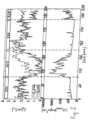
- the introduction of the fluid with the nozzle actuated in the ON position results in the O 2 concentration measured locally in the exhaust gas stream generated in the combustion zone (shown in thick solid lines) being equal to the global one, ie the total in the exhaust gas generated in the combustion chamber present O 2 concentration (shown in thin dashed lines), approximately corresponds.
- the nozzle is not actuated in the OFF position, the locally measured O 2 concentration is significantly lower than the globally measured one.
Landscapes
- Engineering & Computer Science (AREA)
- Mechanical Engineering (AREA)
- General Engineering & Computer Science (AREA)
- Chemical & Material Sciences (AREA)
- Combustion & Propulsion (AREA)
- Incineration Of Waste (AREA)
- Air Supply (AREA)
- Combustion Of Fluid Fuel (AREA)
Claims (8)
- Procédé pour l'optimisation de la combustion de gaz d'échappement d'un incinérateur comprenant les étapes suivantes:la matière solide (2) à incinérer est introduite par une entrée (6) dans une chambre de combustion (8) définissant un espace de combustion primaire (12),la matière solide (2) dans l'espace de combustion primaire (12), sous la forme d'un lit de combustion (14) acheminé sur une grille de combustion (16), est incinérée avec admission d'air primaire et la matière solide incinérée est déchargée de l'espace de combustion primaire (12) par une sortie (18) disposée à l'opposé par rapport à la direction d'acheminement (F) de l'entrée (6), etles gaz de combustion primaires dégagés pendant la combustion de la matière solide (2) sont incinérés avec admission d'air secondaire dans une chambre de combustion secondaire (28) définissant un espace de combustion secondaire (27) et disposée en aval de la chambre de combustion (8) par rapport à la direction d'écoulement desdits gaz de combustion primaires,les gaz d'échappement contenant les gaz de combustion primaires étant homogénéisés dans une zone de mélange (26) à l'aide d'un fluide introduit au moyen d'une buse (24a, 24b, 24c) avant d'entrer dans l'espace de combustion secondaire (27),la zone de mélange (26) étant reliée au moins approximativement directement dans la direction d'écoulement des gaz d'échappement au lit de combustion (14),caractérisé en ce que la vitesse de sortie du fluide de la buse (24a, 24b, 24c) est de 40 à 120 m/s, et en ce que la buse (24a, 24b, 24c) est orientée avec un angle de -10° à +10° par rapport à l'inclinaison de la grille de combustion (16), de sorte que dans la zone de mélange (26), les gaz de combustion primaires provenant, d'une zone de séchage et de combustion des cendres sont mélangés avec les gaz de combustion primaires provenant d'une zone d'allumage et de combustion.
- Procédé selon l'une des revendications précédentes, caractérisé en ce que la vitesse de sortie du fluide de la buse (24a, 24b, 24c) est de 90 m/s.
- Procédé selon l'une des revendications précédentes, caractérisé en ce que la buse (24a, 24b, 24c) est orientée avec un angle de -5° à +5° par rapport à l'inclinaison de la grille de combustion (16).
- Procédé selon l'une des revendications précédentes, caractérisé en ce que le fluide comprend un gaz de fumée retourné d'une zone raccordée en aval de l'espace de combustion secondaire (27).
- Procédé selon la revendication 4, caractérisé en ce que la quantité de gaz de fumée introduite est 5% à 35%, préférablement approximativement 20%, de la quantité d'air primaire admise.
- Procédé selon l'une des revendications précédentes, caractérisé en ce que l'injection du fluide est réalisée au moyen d'une buse (24a) disposée dans une région de la chambre de combustion (8) du côté de l'entrée.
- Procédé selon la revendication 4 ou 5, caractérisé en ce que la buse (24a, 24b, 24c) présente un tube extérieur et un tube intérieur qui s'étend dans la direction axiale du tube extérieur et qui est entouré par celui-ci, le tube intérieur étant conçu pour la conduite du gaz de fumée et le tube extérieur étant conçu pour la conduite d'air.
- Procédé selon l'une des revendications précédentes, caractérisé en ce que le fluide est introduit au moyen d'au moins deux buses (24a, 24b, 24c), préférablement d'au moins six buses.
Priority Applications (4)
| Application Number | Priority Date | Filing Date | Title |
|---|---|---|---|
| NO12712955A NO2691701T3 (fr) | 2011-03-29 | 2012-03-28 | |
| PL12712955.9T PL2691701T5 (pl) | 2011-03-29 | 2012-03-28 | Sposób optymalizacji wypalania gazów odpadowych spalarni |
| EP12712955.9A EP2691701B2 (fr) | 2011-03-29 | 2012-03-28 | Procédé d'optimisation de la combustion totale des gaz d'échappement d'une installation de combustion |
| RS20171117A RS56483B2 (sr) | 2011-03-29 | 2012-03-28 | Postupak optimizacije naknadnog sagorevanja gasova postrojenja za sagorevanje |
Applications Claiming Priority (3)
| Application Number | Priority Date | Filing Date | Title |
|---|---|---|---|
| EP11002575A EP2505919A1 (fr) | 2011-03-29 | 2011-03-29 | Procédé d'optimisation de la combustion des gaz d'échappement d'une installation de combustion par homogénéisation des gaz de fumée dessus du lit de combustion réalisée par injection des gaz de fumée |
| EP12712955.9A EP2691701B2 (fr) | 2011-03-29 | 2012-03-28 | Procédé d'optimisation de la combustion totale des gaz d'échappement d'une installation de combustion |
| PCT/EP2012/001361 WO2012130446A1 (fr) | 2011-03-29 | 2012-03-28 | Procédé d'optimisation de la combustion totale des gaz d'échappement d'une installation de combustion |
Publications (3)
| Publication Number | Publication Date |
|---|---|
| EP2691701A1 EP2691701A1 (fr) | 2014-02-05 |
| EP2691701B1 EP2691701B1 (fr) | 2017-08-23 |
| EP2691701B2 true EP2691701B2 (fr) | 2024-03-20 |
Family
ID=44501668
Family Applications (2)
| Application Number | Title | Priority Date | Filing Date |
|---|---|---|---|
| EP11002575A Withdrawn EP2505919A1 (fr) | 2011-03-29 | 2011-03-29 | Procédé d'optimisation de la combustion des gaz d'échappement d'une installation de combustion par homogénéisation des gaz de fumée dessus du lit de combustion réalisée par injection des gaz de fumée |
| EP12712955.9A Active EP2691701B2 (fr) | 2011-03-29 | 2012-03-28 | Procédé d'optimisation de la combustion totale des gaz d'échappement d'une installation de combustion |
Family Applications Before (1)
| Application Number | Title | Priority Date | Filing Date |
|---|---|---|---|
| EP11002575A Withdrawn EP2505919A1 (fr) | 2011-03-29 | 2011-03-29 | Procédé d'optimisation de la combustion des gaz d'échappement d'une installation de combustion par homogénéisation des gaz de fumée dessus du lit de combustion réalisée par injection des gaz de fumée |
Country Status (9)
| Country | Link |
|---|---|
| US (1) | US20140182492A1 (fr) |
| EP (2) | EP2505919A1 (fr) |
| JP (1) | JP2014513786A (fr) |
| ES (1) | ES2647667T5 (fr) |
| FI (1) | FI2691701T4 (fr) |
| NO (1) | NO2691701T3 (fr) |
| PL (1) | PL2691701T5 (fr) |
| RS (1) | RS56483B2 (fr) |
| WO (1) | WO2012130446A1 (fr) |
Families Citing this family (5)
| Publication number | Priority date | Publication date | Assignee | Title |
|---|---|---|---|---|
| JP2015068517A (ja) * | 2013-09-27 | 2015-04-13 | 日立造船株式会社 | 焼却炉における燃焼運転方法および焼却炉 |
| JP6260058B2 (ja) * | 2014-09-12 | 2018-01-17 | 三菱重工環境・化学エンジニアリング株式会社 | ストーカ式焼却炉 |
| JP6992194B2 (ja) * | 2018-10-05 | 2022-01-13 | 三菱重工業株式会社 | ストーカ式焼却設備及び被焼却物の焼却方法 |
| US10816197B2 (en) * | 2018-12-07 | 2020-10-27 | Eco Burn Inc. | System for the dynamic movement of waste in an incinerator |
| PH12021552189A1 (en) * | 2019-03-15 | 2023-01-04 | Hitachi Zosen Corp | Incinerator |
Citations (5)
| Publication number | Priority date | Publication date | Assignee | Title |
|---|---|---|---|---|
| US5313895A (en) † | 1990-11-22 | 1994-05-24 | Hitachi Zosen Corporation | Method of inhibiting formation of unburned substances in refuse incinerator, and refuse incinerator |
| EP1077077A2 (fr) † | 1999-08-12 | 2001-02-21 | ABB (Schweiz) AG | Procédé de traitement thermique de matières solides |
| EP1081434A1 (fr) † | 1999-08-30 | 2001-03-07 | Von Roll Umwelttechnik AG | Dispositif pour générer un flux gazeux rotatif |
| EP1508745A2 (fr) † | 2003-08-22 | 2005-02-23 | Fisia Babcock Environment GmbH | Méthode pour réduire la production de NOx dans les chambres de combustion et équipement pour la mise en oeuvre de la méthode |
| DE102004037442A1 (de) † | 2004-08-02 | 2006-03-16 | Alstom Technology Ltd | Verfahren zur thermischen Behandlung von Abfall in einer thermischen Abfallbehandlungsanlage sowie thermische Abfallbehandlungsanlage |
Family Cites Families (20)
| Publication number | Priority date | Publication date | Assignee | Title |
|---|---|---|---|---|
| DE3716088A1 (de) * | 1987-04-09 | 1989-02-02 | Muellverbrennungsanlage Wupper | Verfahren zum verbrennen insbesondere von muell |
| JPH04350411A (ja) * | 1990-11-22 | 1992-12-04 | Hitachi Zosen Corp | ごみ焼却炉における未燃分発生抑制方法 |
| JP2662746B2 (ja) * | 1991-04-04 | 1997-10-15 | 日立造船株式会社 | 火格子型ごみ焼却炉 |
| JP2758090B2 (ja) * | 1991-10-21 | 1998-05-25 | 株式会社クボタ | 焼却炉におけるco制御方法 |
| JP3596690B2 (ja) * | 1995-06-15 | 2004-12-02 | 石川島播磨重工業株式会社 | 電気炉におけるNOxの発生低減方法およびその装置 |
| JP3210859B2 (ja) * | 1996-05-01 | 2001-09-25 | 株式会社クボタ | ゴミ焼却炉の二次燃焼ガス供給機構 |
| JPH10110926A (ja) * | 1996-08-14 | 1998-04-28 | Nippon Sanso Kk | 燃焼式除害装置 |
| JPH10205734A (ja) * | 1997-01-14 | 1998-08-04 | Takuma Co Ltd | ストーカ式燃焼炉における2次空気の供給方法 |
| JP3319327B2 (ja) | 1997-03-26 | 2002-08-26 | 日本鋼管株式会社 | ごみ焼却炉の燃焼制御方法およびその装置 |
| JPH10288325A (ja) * | 1997-04-16 | 1998-10-27 | N K K Plant Kensetsu Kk | ごみ焼却炉燃焼排ガス中のダイオキシン類発生抑制方法 |
| CN1218141C (zh) | 1998-05-11 | 2005-09-07 | 马丁环保及能源技术有限责任公司 | 固体物料热处理的方法 |
| NL1015519C2 (nl) * | 2000-06-14 | 2001-12-28 | Amsterdam Gem Dienst Afvalverw | Rookgasrecirculatie bij een afvalverbrandingsinstallatie. |
| DE10051733B4 (de) * | 2000-10-18 | 2005-08-04 | Fraunhofer-Gesellschaft zur Förderung der angewandten Forschung e.V. | Verfahren zur gestuften Verbrennung von Brennstoffen |
| JP3661662B2 (ja) * | 2002-03-28 | 2005-06-15 | Jfeエンジニアリング株式会社 | 廃棄物焼却灰中の金属回収方法および廃棄物焼却炉 |
| JP4479655B2 (ja) * | 2003-04-18 | 2010-06-09 | Jfeエンジニアリング株式会社 | 火格子式廃棄物焼却炉及びその燃焼制御方法 |
| EP1899058A1 (fr) * | 2005-04-29 | 2008-03-19 | W.R. Grace & Co.-Conn. | Compositions de reduction des nox convenant pour les processus de ccf a combustion partielle |
| EP1726876B1 (fr) * | 2005-05-27 | 2015-05-06 | Takuma Co., Ltd. | Méthode améliorée pour la combustion des déchets solides |
| DE102006005464B3 (de) | 2006-02-07 | 2007-07-05 | Forschungszentrum Karlsruhe Gmbh | Verfahren zur primärseitigen Stickoxidminderung in einem zweistufigen Verbrennungsprozess |
| US7975628B2 (en) * | 2006-09-13 | 2011-07-12 | Martin GmbH für Umwelt- und Energietechnik | Method for supplying combustion gas in incineration systems |
| JP5219468B2 (ja) * | 2007-11-15 | 2013-06-26 | 日立造船株式会社 | 二次燃焼室における二次燃焼空気の吹き込み方法 |
-
2011
- 2011-03-29 EP EP11002575A patent/EP2505919A1/fr not_active Withdrawn
-
2012
- 2012-03-28 PL PL12712955.9T patent/PL2691701T5/pl unknown
- 2012-03-28 WO PCT/EP2012/001361 patent/WO2012130446A1/fr not_active Ceased
- 2012-03-28 NO NO12712955A patent/NO2691701T3/no unknown
- 2012-03-28 RS RS20171117A patent/RS56483B2/sr unknown
- 2012-03-28 ES ES12712955T patent/ES2647667T5/es active Active
- 2012-03-28 EP EP12712955.9A patent/EP2691701B2/fr active Active
- 2012-03-28 US US14/008,798 patent/US20140182492A1/en not_active Abandoned
- 2012-03-28 FI FIEP12712955.9T patent/FI2691701T4/en active
- 2012-03-28 JP JP2014501477A patent/JP2014513786A/ja active Pending
Patent Citations (5)
| Publication number | Priority date | Publication date | Assignee | Title |
|---|---|---|---|---|
| US5313895A (en) † | 1990-11-22 | 1994-05-24 | Hitachi Zosen Corporation | Method of inhibiting formation of unburned substances in refuse incinerator, and refuse incinerator |
| EP1077077A2 (fr) † | 1999-08-12 | 2001-02-21 | ABB (Schweiz) AG | Procédé de traitement thermique de matières solides |
| EP1081434A1 (fr) † | 1999-08-30 | 2001-03-07 | Von Roll Umwelttechnik AG | Dispositif pour générer un flux gazeux rotatif |
| EP1508745A2 (fr) † | 2003-08-22 | 2005-02-23 | Fisia Babcock Environment GmbH | Méthode pour réduire la production de NOx dans les chambres de combustion et équipement pour la mise en oeuvre de la méthode |
| DE102004037442A1 (de) † | 2004-08-02 | 2006-03-16 | Alstom Technology Ltd | Verfahren zur thermischen Behandlung von Abfall in einer thermischen Abfallbehandlungsanlage sowie thermische Abfallbehandlungsanlage |
Non-Patent Citations (5)
| Title |
|---|
| DD, MASSNAHMEN ZUR MINDERUNG FEUERRAUMSEITIGER KORROSIONEN, no. hh † |
| F. KRÜL L: "Verfahren zur nummerischen Simulation von Müllrostfeuerung", DISSERTATION, 2001, pages 1 - 237 † |
| KRULL: "Die Auswirkung unterschiedlicher Sekundärluftverteilungen auf den Verbrennungsablauf in einer Müllrostfeuerung", pages 1 - 6 † |
| OBERNBERGER: "Abbrand- und NOx-Simulation für Biomassefeuerung", BMVIT, September 2003 (2003-09-01), pages 1 - 155 † |
| REIMANN D.O.: "Rostfeuerung zur Abfallverbrennung", article FERDINAND KRULL, WALTER BIENERT: "Von der konventionellen W alzenrostfeuerung zurfreiprogrammierbaren Feuerleistungsregelung mitOptimierung der Feuerraumgeometriein der MV A Diisseldorf", pages: 519 - 546 † |
Also Published As
| Publication number | Publication date |
|---|---|
| EP2505919A1 (fr) | 2012-10-03 |
| RS56483B2 (sr) | 2024-04-30 |
| JP2014513786A (ja) | 2014-06-05 |
| US20140182492A1 (en) | 2014-07-03 |
| EP2691701A1 (fr) | 2014-02-05 |
| WO2012130446A1 (fr) | 2012-10-04 |
| NO2691701T3 (fr) | 2018-01-20 |
| FI2691701T4 (en) | 2024-04-04 |
| EP2691701B1 (fr) | 2017-08-23 |
| PL2691701T5 (pl) | 2024-07-15 |
| RS56483B1 (sr) | 2018-01-31 |
| ES2647667T3 (es) | 2017-12-26 |
| ES2647667T5 (es) | 2024-09-19 |
| PL2691701T3 (pl) | 2018-01-31 |
Similar Documents
| Publication | Publication Date | Title |
|---|---|---|
| EP0111874A1 (fr) | Installation pour brûler la poussière de charbon | |
| DE2461078A1 (de) | Verfahren zur verminderung von schadstoffen bei verbrennungsvorgaengen und vorrichtung zur durchfuehrung desselben | |
| EP0139085A1 (fr) | Procédé et brûleur pour la combustion des combustibles liquides ou gazeux avec diminution de la formation de NOx | |
| DE2300522A1 (de) | Vorrichtung zum verbrennen von brennbzw. treibstoffen | |
| DE3716088A1 (de) | Verfahren zum verbrennen insbesondere von muell | |
| EP2691701B2 (fr) | Procédé d'optimisation de la combustion totale des gaz d'échappement d'une installation de combustion | |
| WO1999058902A1 (fr) | Procede de traitement thermique de matieres solides | |
| DE4230311C1 (de) | Verfahren und Verbrennungsofen zum Verbrennen von Abfällen | |
| DE4402172C2 (de) | Verfahren zur Verbrennung von Brennstoff und Anlage zur Durchführung des Verfahrens | |
| EP2044368B1 (fr) | Dispositif thermique de purification des gaz d'échappement et procédé pour la purification thermique des gaz d'échappement | |
| EP3260776B1 (fr) | Système de lance, citerne comprenant un système de lance et procédé de réduction de nox | |
| EP0611919B1 (fr) | Procédé d'alimentation de gaz de comburant à un incinérateur avec un foyer avec grille et dispositif pour la mise en oeuvre du procédé | |
| DE3627086A1 (de) | Verfahren und anordnung zum entfernen von stickstoffoxiden aus rauchgasen | |
| DE102004037442B4 (de) | Verfahren zur thermischen Behandlung von Abfall in einer thermischen Abfallbehandlungsanlage sowie thermische Abfallbehandlungsanlage | |
| EP1754937A2 (fr) | Tête de brûleur et procédé pour brûler du combustible | |
| DE10342498B4 (de) | Verfahren und Vorrichtung für die thermische Abgasreinigung | |
| DE3625397C2 (fr) | ||
| DE2612302C2 (de) | Verfahren zur Verbrennung organische Bestandteile enthaltender Abwässer | |
| DE19504667B4 (de) | Brenneranlage für Zementöfen | |
| DE2816282C2 (de) | Müllverbrennungsofen mit einem Wirbelbett | |
| DE3309905C2 (de) | Verfahren und Vorrichtung zum Verbrennen fester Brennstoffe in pulverisierter Form | |
| DE69313415T2 (de) | Anlage und Verfahren zur Abfallverbrennung | |
| DE102017005917A1 (de) | Verbrennungsverfahren und mehrstufiger Brenner | |
| DE102010046858B4 (de) | Heizkessel und Wärmeversorgungsanlage für Festbrennstoffe sowie ein Verfahren zur Verbrennung von Festbrennstoffen | |
| EP0703413A1 (fr) | Chambre de combustion d'une turbine à gaz |
Legal Events
| Date | Code | Title | Description |
|---|---|---|---|
| PUAI | Public reference made under article 153(3) epc to a published international application that has entered the european phase |
Free format text: ORIGINAL CODE: 0009012 |
|
| 17P | Request for examination filed |
Effective date: 20130923 |
|
| AK | Designated contracting states |
Kind code of ref document: A1 Designated state(s): AL AT BE BG CH CY CZ DE DK EE ES FI FR GB GR HR HU IE IS IT LI LT LU LV MC MK MT NL NO PL PT RO RS SE SI SK SM TR |
|
| RIN1 | Information on inventor provided before grant (corrected) |
Inventor name: WALDNER, MAURICE, HENRI |
|
| DAX | Request for extension of the european patent (deleted) | ||
| 17Q | First examination report despatched |
Effective date: 20160303 |
|
| RIC1 | Information provided on ipc code assigned before grant |
Ipc: F23G 5/16 20060101AFI20170208BHEP Ipc: F23L 7/00 20060101ALI20170208BHEP Ipc: F23L 9/02 20060101ALI20170208BHEP |
|
| GRAP | Despatch of communication of intention to grant a patent |
Free format text: ORIGINAL CODE: EPIDOSNIGR1 |
|
| STAA | Information on the status of an ep patent application or granted ep patent |
Free format text: STATUS: GRANT OF PATENT IS INTENDED |
|
| INTG | Intention to grant announced |
Effective date: 20170322 |
|
| GRAS | Grant fee paid |
Free format text: ORIGINAL CODE: EPIDOSNIGR3 |
|
| GRAA | (expected) grant |
Free format text: ORIGINAL CODE: 0009210 |
|
| STAA | Information on the status of an ep patent application or granted ep patent |
Free format text: STATUS: THE PATENT HAS BEEN GRANTED |
|
| AK | Designated contracting states |
Kind code of ref document: B1 Designated state(s): AL AT BE BG CH CY CZ DE DK EE ES FI FR GB GR HR HU IE IS IT LI LT LU LV MC MK MT NL NO PL PT RO RS SE SI SK SM TR |
|
| REG | Reference to a national code |
Ref country code: GB Ref legal event code: FG4D Free format text: NOT ENGLISH |
|
| REG | Reference to a national code |
Ref country code: CH Ref legal event code: EP Ref country code: CH Ref legal event code: NV Representative=s name: PATENTANWAELTE SCHAAD, BALASS, MENZL AND PARTN, CH |
|
| REG | Reference to a national code |
Ref country code: AT Ref legal event code: REF Ref document number: 921750 Country of ref document: AT Kind code of ref document: T Effective date: 20170915 |
|
| REG | Reference to a national code |
Ref country code: IE Ref legal event code: FG4D Free format text: LANGUAGE OF EP DOCUMENT: GERMAN |
|
| REG | Reference to a national code |
Ref country code: DE Ref legal event code: R096 Ref document number: 502012011081 Country of ref document: DE |
|
| REG | Reference to a national code |
Ref country code: SE Ref legal event code: TRGR |
|
| REG | Reference to a national code |
Ref country code: NL Ref legal event code: FP |
|
| REG | Reference to a national code |
Ref country code: ES Ref legal event code: FG2A Ref document number: 2647667 Country of ref document: ES Kind code of ref document: T3 Effective date: 20171226 |
|
| REG | Reference to a national code |
Ref country code: LT Ref legal event code: MG4D |
|
| REG | Reference to a national code |
Ref country code: NO Ref legal event code: T2 Effective date: 20170823 |
|
| PG25 | Lapsed in a contracting state [announced via postgrant information from national office to epo] |
Ref country code: LT Free format text: LAPSE BECAUSE OF FAILURE TO SUBMIT A TRANSLATION OF THE DESCRIPTION OR TO PAY THE FEE WITHIN THE PRESCRIBED TIME-LIMIT Effective date: 20170823 Ref country code: HR Free format text: LAPSE BECAUSE OF FAILURE TO SUBMIT A TRANSLATION OF THE DESCRIPTION OR TO PAY THE FEE WITHIN THE PRESCRIBED TIME-LIMIT Effective date: 20170823 |
|
| PG25 | Lapsed in a contracting state [announced via postgrant information from national office to epo] |
Ref country code: IS Free format text: LAPSE BECAUSE OF FAILURE TO SUBMIT A TRANSLATION OF THE DESCRIPTION OR TO PAY THE FEE WITHIN THE PRESCRIBED TIME-LIMIT Effective date: 20171223 Ref country code: LV Free format text: LAPSE BECAUSE OF FAILURE TO SUBMIT A TRANSLATION OF THE DESCRIPTION OR TO PAY THE FEE WITHIN THE PRESCRIBED TIME-LIMIT Effective date: 20170823 Ref country code: BG Free format text: LAPSE BECAUSE OF FAILURE TO SUBMIT A TRANSLATION OF THE DESCRIPTION OR TO PAY THE FEE WITHIN THE PRESCRIBED TIME-LIMIT Effective date: 20171123 Ref country code: GR Free format text: LAPSE BECAUSE OF FAILURE TO SUBMIT A TRANSLATION OF THE DESCRIPTION OR TO PAY THE FEE WITHIN THE PRESCRIBED TIME-LIMIT Effective date: 20171124 |
|
| REG | Reference to a national code |
Ref country code: FR Ref legal event code: PLFP Year of fee payment: 7 |
|
| PG25 | Lapsed in a contracting state [announced via postgrant information from national office to epo] |
Ref country code: CZ Free format text: LAPSE BECAUSE OF FAILURE TO SUBMIT A TRANSLATION OF THE DESCRIPTION OR TO PAY THE FEE WITHIN THE PRESCRIBED TIME-LIMIT Effective date: 20170823 Ref country code: RO Free format text: LAPSE BECAUSE OF FAILURE TO SUBMIT A TRANSLATION OF THE DESCRIPTION OR TO PAY THE FEE WITHIN THE PRESCRIBED TIME-LIMIT Effective date: 20170823 Ref country code: DK Free format text: LAPSE BECAUSE OF FAILURE TO SUBMIT A TRANSLATION OF THE DESCRIPTION OR TO PAY THE FEE WITHIN THE PRESCRIBED TIME-LIMIT Effective date: 20170823 |
|
| REG | Reference to a national code |
Ref country code: DE Ref legal event code: R026 Ref document number: 502012011081 Country of ref document: DE |
|
| PLBI | Opposition filed |
Free format text: ORIGINAL CODE: 0009260 |
|
| PG25 | Lapsed in a contracting state [announced via postgrant information from national office to epo] |
Ref country code: SM Free format text: LAPSE BECAUSE OF FAILURE TO SUBMIT A TRANSLATION OF THE DESCRIPTION OR TO PAY THE FEE WITHIN THE PRESCRIBED TIME-LIMIT Effective date: 20170823 Ref country code: EE Free format text: LAPSE BECAUSE OF FAILURE TO SUBMIT A TRANSLATION OF THE DESCRIPTION OR TO PAY THE FEE WITHIN THE PRESCRIBED TIME-LIMIT Effective date: 20170823 Ref country code: SK Free format text: LAPSE BECAUSE OF FAILURE TO SUBMIT A TRANSLATION OF THE DESCRIPTION OR TO PAY THE FEE WITHIN THE PRESCRIBED TIME-LIMIT Effective date: 20170823 |
|
| PLAX | Notice of opposition and request to file observation + time limit sent |
Free format text: ORIGINAL CODE: EPIDOSNOBS2 |
|
| 26 | Opposition filed |
Opponent name: DOOSAN LENTJES GMBH Effective date: 20180517 |
|
| PG25 | Lapsed in a contracting state [announced via postgrant information from national office to epo] |
Ref country code: SI Free format text: LAPSE BECAUSE OF FAILURE TO SUBMIT A TRANSLATION OF THE DESCRIPTION OR TO PAY THE FEE WITHIN THE PRESCRIBED TIME-LIMIT Effective date: 20170823 |
|
| PG25 | Lapsed in a contracting state [announced via postgrant information from national office to epo] |
Ref country code: MT Free format text: LAPSE BECAUSE OF FAILURE TO SUBMIT A TRANSLATION OF THE DESCRIPTION OR TO PAY THE FEE WITHIN THE PRESCRIBED TIME-LIMIT Effective date: 20170823 |
|
| PLBB | Reply of patent proprietor to notice(s) of opposition received |
Free format text: ORIGINAL CODE: EPIDOSNOBS3 |
|
| PG25 | Lapsed in a contracting state [announced via postgrant information from national office to epo] |
Ref country code: MC Free format text: LAPSE BECAUSE OF FAILURE TO SUBMIT A TRANSLATION OF THE DESCRIPTION OR TO PAY THE FEE WITHIN THE PRESCRIBED TIME-LIMIT Effective date: 20170823 |
|
| REG | Reference to a national code |
Ref country code: BE Ref legal event code: MM Effective date: 20180331 |
|
| PG25 | Lapsed in a contracting state [announced via postgrant information from national office to epo] |
Ref country code: LU Free format text: LAPSE BECAUSE OF NON-PAYMENT OF DUE FEES Effective date: 20180328 |
|
| PG25 | Lapsed in a contracting state [announced via postgrant information from national office to epo] |
Ref country code: BE Free format text: LAPSE BECAUSE OF NON-PAYMENT OF DUE FEES Effective date: 20180331 |
|
| REG | Reference to a national code |
Ref country code: AT Ref legal event code: MM01 Ref document number: 921750 Country of ref document: AT Kind code of ref document: T Effective date: 20180328 |
|
| PG25 | Lapsed in a contracting state [announced via postgrant information from national office to epo] |
Ref country code: AT Free format text: LAPSE BECAUSE OF NON-PAYMENT OF DUE FEES Effective date: 20180328 |
|
| APBM | Appeal reference recorded |
Free format text: ORIGINAL CODE: EPIDOSNREFNO |
|
| APBP | Date of receipt of notice of appeal recorded |
Free format text: ORIGINAL CODE: EPIDOSNNOA2O |
|
| APAH | Appeal reference modified |
Free format text: ORIGINAL CODE: EPIDOSCREFNO |
|
| PG25 | Lapsed in a contracting state [announced via postgrant information from national office to epo] |
Ref country code: HU Free format text: LAPSE BECAUSE OF FAILURE TO SUBMIT A TRANSLATION OF THE DESCRIPTION OR TO PAY THE FEE WITHIN THE PRESCRIBED TIME-LIMIT; INVALID AB INITIO Effective date: 20120328 Ref country code: PT Free format text: LAPSE BECAUSE OF FAILURE TO SUBMIT A TRANSLATION OF THE DESCRIPTION OR TO PAY THE FEE WITHIN THE PRESCRIBED TIME-LIMIT Effective date: 20170823 |
|
| APBQ | Date of receipt of statement of grounds of appeal recorded |
Free format text: ORIGINAL CODE: EPIDOSNNOA3O |
|
| PG25 | Lapsed in a contracting state [announced via postgrant information from national office to epo] |
Ref country code: CY Free format text: LAPSE BECAUSE OF FAILURE TO SUBMIT A TRANSLATION OF THE DESCRIPTION OR TO PAY THE FEE WITHIN THE PRESCRIBED TIME-LIMIT Effective date: 20170823 Ref country code: MK Free format text: LAPSE BECAUSE OF NON-PAYMENT OF DUE FEES Effective date: 20170823 |
|
| PG25 | Lapsed in a contracting state [announced via postgrant information from national office to epo] |
Ref country code: AL Free format text: LAPSE BECAUSE OF FAILURE TO SUBMIT A TRANSLATION OF THE DESCRIPTION OR TO PAY THE FEE WITHIN THE PRESCRIBED TIME-LIMIT Effective date: 20170823 |
|
| P01 | Opt-out of the competence of the unified patent court (upc) registered |
Effective date: 20230506 |
|
| APBU | Appeal procedure closed |
Free format text: ORIGINAL CODE: EPIDOSNNOA9O |
|
| PUAH | Patent maintained in amended form |
Free format text: ORIGINAL CODE: 0009272 |
|
| STAA | Information on the status of an ep patent application or granted ep patent |
Free format text: STATUS: PATENT MAINTAINED AS AMENDED |
|
| 27A | Patent maintained in amended form |
Effective date: 20240320 |
|
| AK | Designated contracting states |
Kind code of ref document: B2 Designated state(s): AL AT BE BG CH CY CZ DE DK EE ES FI FR GB GR HR HU IE IS IT LI LT LU LV MC MK MT NL NO PL PT RO RS SE SI SK SM TR |
|
| REG | Reference to a national code |
Ref country code: DE Ref legal event code: R102 Ref document number: 502012011081 Country of ref document: DE |
|
| PGFP | Annual fee paid to national office [announced via postgrant information from national office to epo] |
Ref country code: RS Payment date: 20240315 Year of fee payment: 13 |
|
| REG | Reference to a national code |
Ref country code: SE Ref legal event code: RPEO |
|
| REG | Reference to a national code |
Ref country code: NL Ref legal event code: FP |
|
| REG | Reference to a national code |
Ref country code: NL Ref legal event code: HC Owner name: KANADEVIA INOVA AG; CH Free format text: DETAILS ASSIGNMENT: CHANGE OF OWNER(S), CHANGE OF OWNER(S) NAME; FORMER OWNER NAME: HITACHI ZOSEN INOVA AG Effective date: 20250320 |
|
| PGFP | Annual fee paid to national office [announced via postgrant information from national office to epo] |
Ref country code: PL Payment date: 20250224 Year of fee payment: 14 |
|
| PGFP | Annual fee paid to national office [announced via postgrant information from national office to epo] |
Ref country code: ES Payment date: 20250428 Year of fee payment: 14 |
|
| REG | Reference to a national code |
Ref country code: DE Ref legal event code: R081 Ref document number: 502012011081 Country of ref document: DE Owner name: KANADEVIA INOVA AG, CH Free format text: FORMER OWNER: HITACHI ZOSEN INOVA AG, ZUERICH, CH |
|
| PGFP | Annual fee paid to national office [announced via postgrant information from national office to epo] |
Ref country code: CH Payment date: 20250401 Year of fee payment: 14 |
|
| REG | Reference to a national code |
Ref country code: ES Ref legal event code: PC2A Owner name: KANADEVIA INOVA AG Effective date: 20251211 |
|
| PG25 | Lapsed in a contracting state [announced via postgrant information from national office to epo] |
Ref country code: RS Free format text: LAPSE BECAUSE OF NON-PAYMENT OF DUE FEES Effective date: 20250328 |
|
| REG | Reference to a national code |
Ref country code: CH Ref legal event code: U11 Free format text: ST27 STATUS EVENT CODE: U-0-0-U10-U11 (AS PROVIDED BY THE NATIONAL OFFICE) Effective date: 20260401 |
|
| PGFP | Annual fee paid to national office [announced via postgrant information from national office to epo] |
Ref country code: SE Payment date: 20260319 Year of fee payment: 15 |
|
| PGFP | Annual fee paid to national office [announced via postgrant information from national office to epo] |
Ref country code: GB Payment date: 20260324 Year of fee payment: 15 |
|
| PGFP | Annual fee paid to national office [announced via postgrant information from national office to epo] |
Ref country code: IE Payment date: 20260319 Year of fee payment: 15 Ref country code: NO Payment date: 20260323 Year of fee payment: 15 Ref country code: DE Payment date: 20260319 Year of fee payment: 15 |
|
| PGFP | Annual fee paid to national office [announced via postgrant information from national office to epo] |
Ref country code: FI Payment date: 20260323 Year of fee payment: 15 Ref country code: IT Payment date: 20260324 Year of fee payment: 15 |
|
| PGFP | Annual fee paid to national office [announced via postgrant information from national office to epo] |
Ref country code: NL Payment date: 20260319 Year of fee payment: 15 |
|
| PGFP | Annual fee paid to national office [announced via postgrant information from national office to epo] |
Ref country code: FR Payment date: 20260320 Year of fee payment: 15 |
|
| PGFP | Annual fee paid to national office [announced via postgrant information from national office to epo] |
Ref country code: TR Payment date: 20260324 Year of fee payment: 15 |