EP2704364A1 - Optisches Kommunikationsverfahren zur Übertragung eines Informationssignals - Google Patents
Optisches Kommunikationsverfahren zur Übertragung eines Informationssignals Download PDFInfo
- Publication number
- EP2704364A1 EP2704364A1 EP12183011.1A EP12183011A EP2704364A1 EP 2704364 A1 EP2704364 A1 EP 2704364A1 EP 12183011 A EP12183011 A EP 12183011A EP 2704364 A1 EP2704364 A1 EP 2704364A1
- Authority
- EP
- European Patent Office
- Prior art keywords
- modulated optical
- optical
- signal
- modulated
- accordance
- Prior art date
- Legal status (The legal status is an assumption and is not a legal conclusion. Google has not performed a legal analysis and makes no representation as to the accuracy of the status listed.)
- Withdrawn
Links
- 230000003287 optical effect Effects 0.000 title claims abstract description 215
- 238000000034 method Methods 0.000 title claims abstract description 45
- 238000004891 communication Methods 0.000 title claims abstract description 26
- 230000005540 biological transmission Effects 0.000 claims abstract description 35
- 238000011084 recovery Methods 0.000 claims abstract description 31
- 230000009471 action Effects 0.000 claims abstract description 20
- 230000004044 response Effects 0.000 claims abstract description 17
- 230000015556 catabolic process Effects 0.000 claims abstract description 13
- 238000006731 degradation reaction Methods 0.000 claims abstract description 13
- 238000012544 monitoring process Methods 0.000 claims abstract description 6
- 230000003247 decreasing effect Effects 0.000 claims abstract description 4
- 230000001172 regenerating effect Effects 0.000 claims abstract description 3
- 230000011664 signaling Effects 0.000 claims description 13
- 238000012937 correction Methods 0.000 claims description 8
- 230000006872 improvement Effects 0.000 claims description 7
- 238000012545 processing Methods 0.000 claims description 5
- 230000003139 buffering effect Effects 0.000 claims description 2
- 239000000872 buffer Substances 0.000 description 14
- 230000006870 function Effects 0.000 description 7
- 239000013598 vector Substances 0.000 description 7
- 239000006185 dispersion Substances 0.000 description 5
- 239000000835 fiber Substances 0.000 description 5
- 230000008569 process Effects 0.000 description 5
- 230000006798 recombination Effects 0.000 description 5
- 238000005215 recombination Methods 0.000 description 5
- 230000008929 regeneration Effects 0.000 description 4
- 238000011069 regeneration method Methods 0.000 description 4
- 230000006978 adaptation Effects 0.000 description 3
- 230000008901 benefit Effects 0.000 description 3
- 230000010287 polarization Effects 0.000 description 3
- 238000006243 chemical reaction Methods 0.000 description 2
- 230000003292 diminished effect Effects 0.000 description 2
- 230000000694 effects Effects 0.000 description 2
- 238000005259 measurement Methods 0.000 description 2
- 230000009022 nonlinear effect Effects 0.000 description 2
- 230000001427 coherent effect Effects 0.000 description 1
- 230000021615 conjugation Effects 0.000 description 1
- 238000010276 construction Methods 0.000 description 1
- 238000005388 cross polarization Methods 0.000 description 1
- 238000001514 detection method Methods 0.000 description 1
- 238000010586 diagram Methods 0.000 description 1
- 238000005265 energy consumption Methods 0.000 description 1
- 230000003116 impacting effect Effects 0.000 description 1
- 230000007246 mechanism Effects 0.000 description 1
- 230000004048 modification Effects 0.000 description 1
- 238000012986 modification Methods 0.000 description 1
- 239000013307 optical fiber Substances 0.000 description 1
- 230000005693 optoelectronics Effects 0.000 description 1
- 230000000737 periodic effect Effects 0.000 description 1
- 238000011002 quantification Methods 0.000 description 1
- 230000009467 reduction Effects 0.000 description 1
- 230000008054 signal transmission Effects 0.000 description 1
- 238000004088 simulation Methods 0.000 description 1
- 239000007787 solid Substances 0.000 description 1
- 230000003595 spectral effect Effects 0.000 description 1
- 230000007704 transition Effects 0.000 description 1
Images


Classifications
-
- H—ELECTRICITY
- H04—ELECTRIC COMMUNICATION TECHNIQUE
- H04B—TRANSMISSION
- H04B10/00—Transmission systems employing electromagnetic waves other than radio-waves, e.g. infrared, visible or ultraviolet light, or employing corpuscular radiation, e.g. quantum communication
- H04B10/03—Arrangements for fault recovery
- H04B10/032—Arrangements for fault recovery using working and protection systems
-
- H—ELECTRICITY
- H04—ELECTRIC COMMUNICATION TECHNIQUE
- H04J—MULTIPLEX COMMUNICATION
- H04J14/00—Optical multiplex systems
- H04J14/02—Wavelength-division multiplex systems
- H04J14/0287—Protection in WDM systems
- H04J14/0293—Optical channel protection
- H04J14/0294—Dedicated protection at the optical channel (1+1)
Definitions
- the invention relates to the technical field of optical communication methods and systems, in particular to optical communications in fiber-based networks.
- LSP Label-Switched Path
- the invention provides an optical communication method for transmitting an information signal, comprising:
- such an optical communication method may comprise one or more of the features below.
- the combining of the plurality of modulated optical signals is performed in accordance with combination parameters, the method further comprising modifying the combination parameters in response to degradation of the quality of transmission of the first modulated optical signal.
- the method further comprises discontinuing the combining of the plurality of modulated optical signals in response to degradation of the quality of transmission of the first modulated optical signal, and processing the second modulated optical signal independently to detect the information signal.
- the recovery action may comprise one or more actions selected in the group consisting of regenerating the second modulated optical signal at an intermediate apparatus between the transmitting apparatus and the receiving apparatus, decreasing a symbol rate of the second modulated optical signal sent from the transmitting apparatus, changing a modulation scheme of the second modulated optical signal sent from the transmitting apparatus to a more robust modulation scheme, changing an error-correction code of the second modulated optical signal sent from the transmitting apparatus to a more robust error-correction code, and discontinuing a best-effort traffic flow modulated onto the second modulated optical signal sent from the transmitting apparatus.
- the method further comprises buffering the received modulated optical signals at the receiving apparatus to compensate for a differential delay between the optical paths.
- the quality of transmission monitoring comprises estimating an optical or electrical signal-to-noise ratio of the modulated optical signals.
- the combining of the plurality of modulated optical signals is performed in accordance with a maximum ratio combining method.
- a variety of diversity combining methods can be used as well, e.g. a selective combining method or an equal gain combining method.
- the method further comprises performing a reversion action and/or modifying combination parameters in accordance with which the combining of the plurality of modulated optical signals is performed, in response to improvement of the quality of transmission of the first modulated optical signal.
- Reversion actions refer to actions that inverse or compensate for the recovery actions previously taken. Reversion actions aim to degrade the quality of transmission of the second modulated optical signal to resume energy savings and/or transmission capacity improvements.
- the reversion action may include steps such as interrupting regeneration of the second modulated optical signal at an intermediate apparatus between the transmitting apparatus and the receiving apparatus to forward the second modulated optical signal transparently, increasing a symbol rate of the second modulated optical signal sent from the transmitting apparatus, changing a modulation scheme of the second modulated optical signal sent from the transmitting apparatus to a less robust, yet more capacity efficient, modulation scheme, or changing an error-correction code of the second modulated optical signal sent from the transmitting apparatus to a less robust, yet more efficient error-correction code, resuming the sending of a best-effort traffic flow modulated onto the second modulated optical signal from the transmitting apparatus, or resuming the combining of the plurality of modulated optical signals.
- the invention also provides an optical communication network, comprising:
- such an optical communication network may comprise one or more of the features below.
- the receiving apparatus further comprises a monitoring module adapted to monitor a quality of transmission of the modulated optical signals.
- the optical communication network further comprises an hybrid optical node located on an optical path of the second modulated optical signal, the hybrid optical node comprising a transparent forwarding section, a regenerated forwarding section, and a recovery control module adapted to switch the second modulated optical signal from the transparent forwarding section to the regenerated forwarding section, i.e. to start regeneration of the second modulated optical signal, in response to receiving the recovery signal.
- the transmitting apparatus further comprises a recovery control module adapted to modify a parameter of the second modulated optical signal in response to receiving the recovery signal, wherein the parameter is selected in the group consisting of bit-rate, symbol rate, modulation scheme and error-correction coding scheme.
- aspects of the invention stem for the observation that the protection connection in a 1+1 LSP protection method permanently consumes resources, whereas the actual time during which the connection is used depends on the rate of failures. For example the probability of a failure caused by a cut fiber is estimated to 4.39 cuts/year/1,000 sheath-miles. This corresponds approximately to one cut per day in a large operator network made up of 100,000 miles of fiber cables.
- aspects of the invention are based on the idea of fmding protected transmission methods that achieve a better capacity in optical networks than 1+1 protection. Aspects of the invention are based on the idea of finding protected transmission methods that achieve a better energy-efficiency in optical networks than 1+1 protection. Aspects of the invention are based on the idea of exploiting the signal redundancy implied by 1+1 protection schemes to obtain a spatial-diversity gain at the receiver.
- aspects of the invention are based on the idea of abstaining from optional energy-consuming and/or capacity consuming steps of the optical signal transmission as long the plurality of instances of the information signal reach the receiver with a sufficient level of quality, and performing those optional energy-consuming and/or capacity consuming steps whenever the spatial-diversity gain obtained at the receiver is diminished or lost.
- an optical communications network 1 is schematically depicted.
- the network comprises a plurality of optical switching nodes A, B, C, D, E, F, G and H interconnected by optical links 2.
- the number of nodes, number of links and topology as shown are purely illustrative.
- the topology could be of any type, e.g. point to point, tree-like, ring-like or mesh.
- the optical switching nodes are transparent nodes, i.e. capable of switching the optical signals in the optical domain without an Optical-to-electronic conversion. Some or all of the optical switching nodes may also be hybrid nodes, i.e. nodes including a transparent forwarding function and a regenerated forwarding function that can be used selectively for switching an optical signal between an input port and an output port of the node.
- hybrid nodes i.e. nodes including a transparent forwarding function and a regenerated forwarding function that can be used selectively for switching an optical signal between an input port and an output port of the node.
- a number of architectures are available to those skilled in the art for implementing such transparent or hybrid optical nodes, e.g. based on components such as wavelength selective switches, optical splitters, power combiners, wavelength multiplexers and demultiplexer, optical gates, and the like.
- Hybrid nodes are of particular interest to build flexible WDM optical networks capable of establishing optical connections which are diverse in terms of path length, source node, destination node and capacity as a function of demand.
- routing and signaling in such a flexible WDM network can be achieved with a GMPLS control plane.
- the optical reach of a transparent optical connection generally evolves inversely to spectral efficiency in a WDM network.
- a 10Gbps transponder is able to reach 3000km while a 100Gbps transponder only achieves 800 to 1200 km. Therefore, a demand for optical regenerations changes as a function of connection length and data-rate.
- Hybrid nodes are one way to cope with such changing demand.
- Figure 1 shows how an information signal can be transmitted from source node A to destination node B in accordance with embodiments of the invention.
- Node A uses a plurality of route-diverse optical connections to transmit a plurality of instances of the same information signal to node B.
- Two such optical connections 3 and 4 are shown on Fig. 1 . Namely, connection 3 takes the path A-C-B and connection 4 takes the path A-D-E-B. More than two connections could be used as well.
- an empty circle represents a node that forwards the optical signal in a transparent manner
- a solid black circle represents a node that forwards the optical signal in a regenerated manner, i.e. with O-E-O conversions.
- the optical connections 3 and 4 are fully transparent in Fig. 1 .
- An actual WDM node generally switches a number of optical connections at the same time and may do so in a transparent manner for some of those connections and in a regenerated manner for the others.
- a combining module 10 exploits the redundant optical connections 3 and 4 (or more).
- the benefits are two-fold. Firstly, a power combining gain is obtained by receiving the modulated information signal twice (or more). Secondly, a diversity gain is obtained since the emitted signal propagates through different physical links, fibers and nodes, thus experiencing potentially different dispersion, noise and non-linear effects.
- SNR Signal-to-noise ratio
- a single information signal x is transmitted over an integer number K (with K ⁇ 2) of optical connections.
- the first optical connection 3 is called the primary path and the optical connection 4 is called secondary path.
- the receiving node B is in charge of combining the optical signals constructively, e.g. with a Maximum Ratio Combining algorithm (MRC), so as to improve the total SNR.
- MRC Maximum Ratio Combining algorithm
- An increase of the optical reach brought by the redundant optical signals enables to spare energy by reducing a number of active regenerators.
- An increase of the SNR brought by the redundant optical signals enables to spare energy by using a more energy-efficient transmission method.
- the graph 6 in Figure 2 illustrates the combination power gain obtained by combining two redundant optical signals at the destination node.
- the power gain depends on the difference between the received power levels of the two optical signals, which is marked in abscissa in dB units.
- OSNR optical SNR
- PTx 58 - Loss / span - NF - G - 10 * log ⁇ 10 # ⁇ spans
- # spans denotes the number of fiber spans along the respective connection path
- PTx is the power per channel launched into each span
- NF refers to the noise figure of the amplifier
- G is the amplifier gain which is typically taken to be equal to the span loss.
- a primary path length is 2000km with 20 spans of 100km while a secondary path length is 2400km with 24 spans of 100km.
- the resulting power combining gain is about 2.7 dB.
- a diversity gain may be also obtained to further contribute to the SNR increase. Since the primary and secondary connections 3 and 4 have different characteristics, hence are not subject to the same dispersion and non-linear effects, potential errors may not occur on the same symbol location. This improves the reliability of the information flow after recombination at the receiver side using spatial diversity combination techniques.
- the above operation at the receiver side is the default operating mode as long as no failure occurs.
- a system controller activates a recovery mechanism to compensate for the resulting SNR degradation.
- regenerators may include a fast sleep mode feature, as described in " Power management of optoelectronic interfaces for dynamic optical networks", A. Morea et al., ECOC 2011 .
- a recovery signal 5 is sent to an intermediate node of the second connection 4, i.e. node E, in order to rapidly transition a regenerator from a sleep mode to an active mode.
- the optical node E rapidly routes the optical connection 4 through the regenerator, whereas the regenerator was previously bypassed.
- the recovery signal 5 that causes the optical node to switches from the transparent forwarding mode to the regenerated forwarding mode can be sent by the destination node B as shown or any other network element, e.g. a control plane element that collects failure detection events.
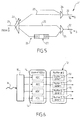
- FIG. 5 illustrates an embodiment of a hybrid WDM optical node 20 that can implement node E.
- a wavelength selective switch 23 is arranged at each WDM input port 21 of the node.
- a power combiner 24 is arranged at each WDM output port 22 of the node. Between the input ports and output ports, the node comprises transparent forwarding paths, as shown at 25, and regenerated forwarding path, as shown at 26.
- a signal regenerator 27 comprises an optical-to-electronic converter, an electronic signal processing section and an electronic-to-optical converter.
- the WSS 23 is adapted to switch the incoming optical signals to either one of the forwarding paths on a wavelength by wavelength basis.
- the power combiner 24 combines the forwarding paths so as to always forward the optical signals regenerated or not regenerated.
- the optical connection 4 is forwarded towards node B through the transparent forwarding path 25.
- the WSS 23 is reconfigured to forward the optical connection 4 towards node B through the regenerated forwarding path 26.
- the optical connection 4 achieves the state shown on Fig. 3 .
- each optical connection corresponds to a single wavelength channel.
- Vector s of size N T denotes the information signal sent by source node A across the K optical connections which are received at the destination node B.
- y i denotes the received vector of size N R over the i th optical connection.
- each received vector y i is first equalized by a channel equalization module 11, i.e. for compensating different effects such as chromatic dispersion, Polarization mode dispersion and cross polarization modulation.
- Channel equalization could consist of blind or non-blind algorithms.
- the resulting equalized vectors z i are then combined constructively in the combining module 10.
- the weights w i are such that each represents the contribution of the connection i to the global estimate ⁇ . For instance, if an optical connection provides a high electrical SNR estimated at the output of the equalizer module 11, its contribution is set to be higher than another optical connection experiencing more severe attenuation and dispersion effects, i.e. due to span length or physical differences in the optical fibers.
- the combining module 10 executes a diversity-combination algorithm such as the maximum ratio combination to maximize the equivalent SNR after recombination. For instance, the equalizer module 11 measures the SNR and provides the measurement to the fallback controller.
- buffer modules 12 with fast access may be provided, preferably with configurable buffer lengths so as to ensure flexibility in case of network reconfiguration.
- Fig. 4 shows the buffer implementation at the receiver side.
- similar buffer modules can be implemented at the transmitter side.
- Figure 6 illustrates an embodiment of the buffer module 12 adapted for high-speed transmission signals formats such a QPSK modulation with polarization multiplexing.
- the buffer module 12 may actually be composed of four parallel buffers 13 in order to have one buffer per Analog-to-Digital Converter 14, i.e. one per quadrature (I and Q) and per polarization (polar 1 and polar 2).
- this embodiment operates with a coherent mixer 15 to detect both phase and amplitude of the received signals.
- the device shown on Fig. 6 is adapted for one incoming wavelength channel 16.
- the depth of a buffer 13 should be selected as a function of the difference in length between the shortest and the longest optical connections. For instance, if that difference is equal to 200km, i.e. about 10 -3 s, the resulting buffer size is about 62.5 Mbytes for a WDM transmission at 25 Gbaud with an oversampling factor of 2 and quantification on 10 bits.
- the power consumption of such buffers is negligible compared to the power savings involved by the switching-off of a regenerator device (e.g. 350 W at 100Gbps).
- the control plane of the network is able to manage the routing and wavelength assignment of the optical connections by taking into account the buffer size limitation as a constraint.
- Fig. 1 shows the network in a first operating mode, which is the normal mode when no failure occurs.
- Fig. 3 shows the network in a second operating mode, which is the fallback mode when a failure prevents at least one optical connection from being diversity-combined with the other connections at the receiving node B.
- the transmitting node A, the receiving node B and the intermediate nodes C, D and E may exchange signaling messages.
- the transmitting node A is sending the same information x over the K lightpaths.
- the receiving node B exploiting this redundant information appropriately through a combination module that substantially extends the equivalent transparent reach of the optical connections, e.g. by several dBs with only two connections as seen in Fig. 2 .
- the extended transparent reach makes it possible to put unnecessary regenerators in a sleep mode and to bypass these inactive regenerators to cross the intermediate nodes in a transparent manner.
- the fallback mode is activated when at least one of the optical signals falls below a given quality threshold. This includes failure affecting a whole optical connection or signal processing issues occurring at the receiving node before the recombination module.
- the consequence of removing at least one of the optical signals from the diversity-combination is a decrease in the equivalent transparent reach. Hence, it may become necessary to switch on one or several regenerators in the remaining optical connections.
- a control plane element of the network that detects such an event propagates a signaling message to the source node A and the destination node B.
- a module referred to as fallback controller 17 triggers recovery actions, such as adjusting the combining weights in the combining module 10 to remove the contribution of the faulty signal and communicating with the regenerators that need to be switched on in the network.
- the selection of a regenerator in response to a particular event has been computed off-line during a configuration phase of the network, so that the fallback controller 17 can rely on look-up tables to select the appropriate address.
- the controller then sends a signaling message to the nodes that require a regenerator to be switched on.
- the destination node B can take appropriate action to revert to the normal mode, i.e. reconfiguring the combining module to combine the repaired signal and sending a signaling message to intermediate nodes in which a regenerator can be turned off and bypassed.
- a control plane element of the network that detects such an event propagates a signaling message to the source node A and/or the destination node B.
- Fig. 4 shows the fallback controller 17 implemented at the receiver side.
- the fallback controller 17 could be implemented at the source node A or in further network elements.
- FIG. 7 to 9 there will be described a second embodiment of the optical network, which also operates in a normal mode and a fallback mode.
- the normal mode is similar to the embodiment of Fig. 1 .
- the destination node combines multiple redundant optical signals to improve the SNR.
- the second embodiment translates this SNR gain into a capacity growth.
- the normal operating mode relies on signal parameter values, such as data rate, symbol rate, modulation order and/or channel coding rate to obtain a higher capacity than the standard capacity obtainable without the diversity-combination step at the receiver.
- the resulting extra-capacity is filled with best effort traffic while the standard capacity conveys QoS-guaranteed traffic.
- the degraded signal is taken out of the diversity-combining process at the receiver side and the other connections are reconfigured to a fall-back mode. Namely, the transmitter and the receiver come back to the standard data rate that does not require the diversity-combining process. At the same time, the best effort traffic carried by the extra capacity is temporarily ignored until the normal mode can be recovered. To switch from one to the other mode, signaling messages are exchanged between the transmitter and the receiver.
- Fig. 1 it is now assumed that the transmitted data rate of both redundant optical connections 3 and 4 is set to R 1 .
- Two connections are shown for the sake of simplicity. However, more than two redundant connections can be combined in the same manner.
- the fallback mode is activated when the optical connection 3 falls below a given quality threshold.
- the consequence of removing at least one optical signal from the diversity-combination is a decrease of the total SNR.
- the destination node B sends a signaling message 30 to the source node A in order to lower the transmission data rate to R 2 with R 2 ⁇ R 1 .
- a new, lower data rate R 3 is selected in the same manner for the remaining connection. The procedure can continue until a single optical connection remains.
- the chosen data rate represents the minimal throughput accepted between source node A and destination node B. This minimal throughput is referred to as guaranteed rate R G , which can carry QoS-guaranteed traffic.
- R G This minimal throughput is referred to as guaranteed rate R G , which can carry QoS-guaranteed traffic.
- the extra-capacity beyond R G is preferably used to convey best effort traffic, i.e. traffic which can be easily pre-empted in the event of a failure.
- the receiving node and/or a control plane element of the network detects that the signal quality falls below a predefined threshold and then propagates a signaling message to inform the source and destination nodes about the event. Once received at the destination node, the event causes the receiver to adjust the combining weights to remove the contribution of the faulty signal.
- the transmitter located at the source node switches to a different data rate by adapting signal parameters such as the channel coding (FEC overhead), the modulation scheme or the symbol rate or a combination of these.
- the receiver at the destination node proceeds to the same adaptation.
- This rate-adaptation is controlled by a controller module 31, which can be located either at the transmitter or the receiver side or at both sides.
- Figure 8 shows an embodiment with the controller module 31 at both sides.
- the rate adaptation process relies on predefined look-up tables loaded in a memory of the node.
- the controller decision process can be made simple.
- Figure 9 illustrates in a qualitative manner the relationship between SNR in abscissae and data rate in ordinates for a number of modulation schemes that are representative of modem optical networks. This information is known in advance and can be stored in the look-up table to assist the controller module 31 in selecting an appropriate modulation scheme and symbol rate as a function of an estimate of the available SNR.
- the controller module 31 selects the best data rate as a function of the estimated SNR value.
- the estimation of the SNR value takes into account the number of currently functional optical connections, whenever this number is decreasing (i.e. in the event that one connection has failed) or increasing (i.e. in the event that one connection was recovered).
- a simple method relies on the OSNR graph of Fig. 2 . Namely, the methods consists in evaluating the difference in length between the shortest connection and the connection which failed or recovered to extrapolate the resulting difference in OSNR, which provides a rough estimate of the SNR loss or gain after combining. Table 1 below illustrates this method. ⁇ OSNR between shortest path and lightpath SNR loss / gain after combining 0.0 dB 3.0 dB -0.5 dB 2.8 dB -1.0 dB 2.5 dB ... ...
- the controller module 31 at the transmitter side could receive periodic measurements of the new SNR value from the receiving node.
- the controller module 31 sends signaling messages so as to set up both the optical transmitter and the optical receiver with the new channel coding rate and/or modulation format and/or symbol rate.
- Fig. 8 is a functional representation of the transmitter 40 in the source node and the receiver 50 in the destination node.
- the receiver 50 comprises the combination module 10 as already described.
- the controller modules 31 exchange signaling messages to convey failure-related information and/or rate-adaptation instructions. When the controller modules 31 at the transmitter side and at the receiver side are informed of a signal failure, the controller modules proceed to adapt the data-rate accordingly.
- the controller modules 31 may interact with different modules in the signal processing device depending on how the rate adaptation is implemented. For instance, the control module 31 drives a FEC module 41 or 51 to vary the coding scheme, a modulation mapper 42 or de-mapper 52 to vary the modulation scheme, or the ADCs 43 and 53 and optical front ends 44 and 54 to vary the symbol rate.
- the receiver 50 may comprise buffers similar to those shown in Fig. 4 or 6 .
- the data rate is varied by reconfiguring the channel decoder (FEC module 41 or 51).
- FEC module 41 or 51 reconfiguring the channel decoder (FEC module 41 or 51).
- This embodiment is based on the observation that a new generation of LDPC-based Soft Decision (SD) FEC consists of two channel coding stages: a first, conventional Reed-Salomon stage and a second LDPC stage.
- SD Soft Decision
- Such LDPC-based FEC causes a 20W-power consumption increase at the receiver side compared to conventional Hard Decision (HD) FEC consisting of a single Reed-Salomon stage.
- HD Hard Decision
- the new generation of SD FEC is more robust and requires an additional 13% overhead on top of the 7% overhead of the HD FEC.
- Current implementations suggest increasing the symbol rate accordingly to maintain the useful data rate, e.g. 100Gbps.
- the transmitter and receiver turn off and bypass the LDPC additional stage.
- the loss of coding robustness caused by deactivating the LDPC stage is compensated by the diversity-combining gain at the receiver side.
- the transmitter and receiver switch on the LDPC stage to have the more robust FEC coding scheme compensate for the SNR loss.
- the symbol rate may be switched between a first, lower symbol rate in the normal mode and a second, higher symbol rate in the fall-back mode, to keep the useful data rate constant despite the additional overhead.
- control modules could be e.g. hardware means like e.g. an ASIC, or a combination of hardware and software means, e.g. an ASIC and an FPGA, or at least one microprocessor and at least one memory with software modules located therein.
Landscapes
- Engineering & Computer Science (AREA)
- Computer Networks & Wireless Communication (AREA)
- Signal Processing (AREA)
- Physics & Mathematics (AREA)
- Electromagnetism (AREA)
- Optical Communication System (AREA)
Priority Applications (2)
| Application Number | Priority Date | Filing Date | Title |
|---|---|---|---|
| EP12183011.1A EP2704364A1 (de) | 2012-09-04 | 2012-09-04 | Optisches Kommunikationsverfahren zur Übertragung eines Informationssignals |
| PCT/EP2013/063886 WO2014037131A2 (en) | 2012-09-04 | 2013-07-02 | Optical communication method for transmitting an information signal |
Applications Claiming Priority (1)
| Application Number | Priority Date | Filing Date | Title |
|---|---|---|---|
| EP12183011.1A EP2704364A1 (de) | 2012-09-04 | 2012-09-04 | Optisches Kommunikationsverfahren zur Übertragung eines Informationssignals |
Publications (1)
| Publication Number | Publication Date |
|---|---|
| EP2704364A1 true EP2704364A1 (de) | 2014-03-05 |
Family
ID=46796446
Family Applications (1)
| Application Number | Title | Priority Date | Filing Date |
|---|---|---|---|
| EP12183011.1A Withdrawn EP2704364A1 (de) | 2012-09-04 | 2012-09-04 | Optisches Kommunikationsverfahren zur Übertragung eines Informationssignals |
Country Status (2)
| Country | Link |
|---|---|
| EP (1) | EP2704364A1 (de) |
| WO (1) | WO2014037131A2 (de) |
Cited By (1)
| Publication number | Priority date | Publication date | Assignee | Title |
|---|---|---|---|---|
| EP3327959A4 (de) * | 2015-11-24 | 2018-09-12 | Mitsubishi Electric Corporation | Optische wiederholungsvorrichtung, optisches übertragungssystem und optisches signalregenerations-/wiederholungsverfahren |
Families Citing this family (2)
| Publication number | Priority date | Publication date | Assignee | Title |
|---|---|---|---|---|
| IT201600096594A1 (it) | 2016-09-27 | 2018-03-27 | Scuola Superiore Di Studi Univ E Di Perfezionamento Santanna | Metodo di gestione di una rete di telecomunicazioni |
| WO2022029864A1 (ja) * | 2020-08-04 | 2022-02-10 | 三菱電機株式会社 | 信号処理装置、信号処理方法、受信器及び光通信システム |
Citations (8)
| Publication number | Priority date | Publication date | Assignee | Title |
|---|---|---|---|---|
| US20020109885A1 (en) * | 2001-02-15 | 2002-08-15 | Ntt Docomo, Inc. | Information transmission system and information transmission method, and, optical space transmission system and optical space transmission method |
| EP1608112A1 (de) * | 2004-06-14 | 2005-12-21 | Broadcom Corporation | Kompensation und Messung der Differentiellen Verzögerung in gebundenen Systemen |
| WO2007025346A1 (en) * | 2005-09-02 | 2007-03-08 | Monash University | Methods and apparatus for optical transmission of digital signals |
| US7336902B1 (en) * | 2002-06-06 | 2008-02-26 | At&T Corp. | Integrated electro-optic hybrid communication system |
| US20110292814A1 (en) * | 2009-02-19 | 2011-12-01 | Hiromitsu Sugahara | Communication path monitoring method and transmission apparatus |
| EP2395684A1 (de) * | 2010-06-08 | 2011-12-14 | Hitachi, Ltd. | Optisches Relaissystem und Netzwerksteuervorrichtung |
| US20110318007A1 (en) * | 2009-03-13 | 2011-12-29 | Nec Corporation | Optical transmission system |
| US20120148260A1 (en) * | 2010-12-13 | 2012-06-14 | Fujitsu Limited | Optical transmitter and optical transmission method |
Family Cites Families (1)
| Publication number | Priority date | Publication date | Assignee | Title |
|---|---|---|---|---|
| JP5398839B2 (ja) * | 2009-09-14 | 2014-01-29 | 日本電信電話株式会社 | 帯域可変通信方法、帯域可変通信装置、伝送帯域決定装置、伝送帯域決定方法、ノード装置、通信路設定システム、及び通信路設定方法 |
-
2012
- 2012-09-04 EP EP12183011.1A patent/EP2704364A1/de not_active Withdrawn
-
2013
- 2013-07-02 WO PCT/EP2013/063886 patent/WO2014037131A2/en not_active Ceased
Patent Citations (8)
| Publication number | Priority date | Publication date | Assignee | Title |
|---|---|---|---|---|
| US20020109885A1 (en) * | 2001-02-15 | 2002-08-15 | Ntt Docomo, Inc. | Information transmission system and information transmission method, and, optical space transmission system and optical space transmission method |
| US7336902B1 (en) * | 2002-06-06 | 2008-02-26 | At&T Corp. | Integrated electro-optic hybrid communication system |
| EP1608112A1 (de) * | 2004-06-14 | 2005-12-21 | Broadcom Corporation | Kompensation und Messung der Differentiellen Verzögerung in gebundenen Systemen |
| WO2007025346A1 (en) * | 2005-09-02 | 2007-03-08 | Monash University | Methods and apparatus for optical transmission of digital signals |
| US20110292814A1 (en) * | 2009-02-19 | 2011-12-01 | Hiromitsu Sugahara | Communication path monitoring method and transmission apparatus |
| US20110318007A1 (en) * | 2009-03-13 | 2011-12-29 | Nec Corporation | Optical transmission system |
| EP2395684A1 (de) * | 2010-06-08 | 2011-12-14 | Hitachi, Ltd. | Optisches Relaissystem und Netzwerksteuervorrichtung |
| US20120148260A1 (en) * | 2010-12-13 | 2012-06-14 | Fujitsu Limited | Optical transmitter and optical transmission method |
Non-Patent Citations (2)
| Title |
|---|
| A. MOREA ET AL.: "Power management of optoelectronic interfaces for dynamic optical networks", ECOC, 2011 |
| INTERNET ENGINEERING TASK FORCE'S RFC 4872 ''RSVP-TE EXTENSIONS FOR E2E GMPLS RECOVERY, May 2007 (2007-05-01) |
Cited By (1)
| Publication number | Priority date | Publication date | Assignee | Title |
|---|---|---|---|---|
| EP3327959A4 (de) * | 2015-11-24 | 2018-09-12 | Mitsubishi Electric Corporation | Optische wiederholungsvorrichtung, optisches übertragungssystem und optisches signalregenerations-/wiederholungsverfahren |
Also Published As
| Publication number | Publication date |
|---|---|
| WO2014037131A2 (en) | 2014-03-13 |
| WO2014037131A3 (en) | 2014-08-21 |
Similar Documents
| Publication | Publication Date | Title |
|---|---|---|
| US10931369B2 (en) | Methods and apparatus for adaptively detecting signal degradation in an optical communication system using the pre-forward error correction bit error rate | |
| Jinno et al. | Distance-adaptive spectrum resource allocation in spectrum-sliced elastic optical path network [topics in optical communications] | |
| EP2251999B1 (de) | Datenübertragungsverfahren und Netzwerk zur Übertragung eines digitalen optischen Signals über optische Übertragungsstrecken und -netzwerke | |
| CN107534517B (zh) | 用于根据第一数据分组生成第二数据分组的方法和装置 | |
| KR101510492B1 (ko) | 광학 전송 시스템 및 이것의 운영 방법 | |
| US8964581B2 (en) | Bandwidth variable communication method, bandwidth variable communication apparatus, transmission bandwidth determination apparatus, transmission bandwidth determination method, node apparatus, communication path setting system, communication path setting | |
| EP2448153B1 (de) | Vorrichtung und System zur optischen Übertragung | |
| JP6962336B2 (ja) | 受信装置、送信装置、光通信システムおよび光通信方法 | |
| US20060127100A1 (en) | Simplified signal regenerator structure | |
| WO2015156858A2 (en) | Systems and methods for managing excess optical capacity and margin in optical networks | |
| JP5266546B2 (ja) | デジタル伝送システム | |
| US7969868B2 (en) | Path-level protection for digitally wrapped payloads | |
| EP2704364A1 (de) | Optisches Kommunikationsverfahren zur Übertragung eines Informationssignals | |
| Dupas et al. | Real-time demonstration of software-defined elastic interface for flexgrid networks | |
| US9306663B2 (en) | Controller, a communication system, a communication method, and a storage medium for storing a communication program | |
| CN110036583A (zh) | 光学通信系统中的子载波分集 | |
| CN107534491B (zh) | 用于第一和第二链路部分之间的再生网络节点的装置和方法 | |
| US11632176B2 (en) | Automatic negotiation of optical transceiver configuration parameters | |
| JP6981101B2 (ja) | ノイズマージン監視及び制御方法 | |
| JP2013150339A (ja) | デジタル伝送システム | |
| US11018763B2 (en) | Network system, management device, and management method | |
| WO2012117564A1 (en) | A wavelength path control system, a wavelength path controlling method, and a storage medium for storing a wavelength path controlling program | |
| Ciaramella et al. | Effective suppression of transient-induced impairments in transparent optical networks | |
| Herbst et al. | Benefits and challenges in transparent optical networks | |
| Das et al. | Protection and Spatial Reuse in Optical Burst Transport (OBT) Networks |
Legal Events
| Date | Code | Title | Description |
|---|---|---|---|
| 17P | Request for examination filed |
Effective date: 20130712 |
|
| AK | Designated contracting states |
Kind code of ref document: A1 Designated state(s): AL AT BE BG CH CY CZ DE DK EE ES FI FR GB GR HR HU IE IS IT LI LT LU LV MC MK MT NL NO PL PT RO RS SE SI SK SM TR |
|
| AX | Request for extension of the european patent |
Extension state: BA ME |
|
| PUAI | Public reference made under article 153(3) epc to a published international application that has entered the european phase |
Free format text: ORIGINAL CODE: 0009012 |
|
| 111Z | Information provided on other rights and legal means of execution |
Free format text: AL AT BE BG CH CY CZ DE DK EE ES FI FR GB GR HR HU IE IS IT LI LT LU LV MC MK MT NL NO PL PT RO RS SE SI SK SM TR Effective date: 20140516 |
|
| RAP1 | Party data changed (applicant data changed or rights of an application transferred) |
Owner name: ALCATEL LUCENT |
|
| RBV | Designated contracting states (corrected) |
Designated state(s): AL AT BE BG CH CY CZ DE DK EE ES FI FR GB GR HR HU IE IS IT LI LT LU LV MC MK MT NL NO PL PT RO RS SE SI SK SM TR |
|
| D11X | Information provided on other rights and legal means of execution (deleted) | ||
| 17Q | First examination report despatched |
Effective date: 20161205 |
|
| STAA | Information on the status of an ep patent application or granted ep patent |
Free format text: STATUS: THE APPLICATION IS DEEMED TO BE WITHDRAWN |
|
| 18D | Application deemed to be withdrawn |
Effective date: 20170419 |