EP2705995B1 - Appareil de commande de véhicule - Google Patents
Appareil de commande de véhicule Download PDFInfo
- Publication number
- EP2705995B1 EP2705995B1 EP13182733.9A EP13182733A EP2705995B1 EP 2705995 B1 EP2705995 B1 EP 2705995B1 EP 13182733 A EP13182733 A EP 13182733A EP 2705995 B1 EP2705995 B1 EP 2705995B1
- Authority
- EP
- European Patent Office
- Prior art keywords
- motor
- rotary member
- intermediate shaft
- driving force
- force transmission
- Prior art date
- Legal status (The legal status is an assumption and is not a legal conclusion. Google has not performed a legal analysis and makes no representation as to the accuracy of the status listed.)
- Active
Links
Images


Classifications
-
- B—PERFORMING OPERATIONS; TRANSPORTING
- B60—VEHICLES IN GENERAL
- B60W—CONJOINT CONTROL OF VEHICLE SUB-UNITS OF DIFFERENT TYPE OR DIFFERENT FUNCTION; CONTROL SYSTEMS SPECIALLY ADAPTED FOR HYBRID VEHICLES; ROAD VEHICLE DRIVE CONTROL SYSTEMS FOR PURPOSES NOT RELATED TO THE CONTROL OF A PARTICULAR SUB-UNIT
- B60W10/00—Conjoint control of vehicle sub-units of different type or different function
- B60W10/10—Conjoint control of vehicle sub-units of different type or different function including control of change-speed gearings
- B60W10/11—Stepped gearings
-
- B—PERFORMING OPERATIONS; TRANSPORTING
- B60—VEHICLES IN GENERAL
- B60K—ARRANGEMENT OR MOUNTING OF PROPULSION UNITS OR OF TRANSMISSIONS IN VEHICLES; ARRANGEMENT OR MOUNTING OF PLURAL DIVERSE PRIME-MOVERS IN VEHICLES; AUXILIARY DRIVES FOR VEHICLES; INSTRUMENTATION OR DASHBOARDS FOR VEHICLES; ARRANGEMENTS IN CONNECTION WITH COOLING, AIR INTAKE, GAS EXHAUST OR FUEL SUPPLY OF PROPULSION UNITS IN VEHICLES
- B60K6/00—Arrangement or mounting of plural diverse prime-movers for mutual or common propulsion, e.g. hybrid propulsion systems comprising electric motors and internal combustion engines
- B60K6/20—Arrangement or mounting of plural diverse prime-movers for mutual or common propulsion, e.g. hybrid propulsion systems comprising electric motors and internal combustion engines the prime-movers consisting of electric motors and internal combustion engines, e.g. HEVs
- B60K6/42—Arrangement or mounting of plural diverse prime-movers for mutual or common propulsion, e.g. hybrid propulsion systems comprising electric motors and internal combustion engines the prime-movers consisting of electric motors and internal combustion engines, e.g. HEVs characterised by the architecture of the hybrid electric vehicle
- B60K6/48—Parallel type
-
- B—PERFORMING OPERATIONS; TRANSPORTING
- B60—VEHICLES IN GENERAL
- B60K—ARRANGEMENT OR MOUNTING OF PROPULSION UNITS OR OF TRANSMISSIONS IN VEHICLES; ARRANGEMENT OR MOUNTING OF PLURAL DIVERSE PRIME-MOVERS IN VEHICLES; AUXILIARY DRIVES FOR VEHICLES; INSTRUMENTATION OR DASHBOARDS FOR VEHICLES; ARRANGEMENTS IN CONNECTION WITH COOLING, AIR INTAKE, GAS EXHAUST OR FUEL SUPPLY OF PROPULSION UNITS IN VEHICLES
- B60K6/00—Arrangement or mounting of plural diverse prime-movers for mutual or common propulsion, e.g. hybrid propulsion systems comprising electric motors and internal combustion engines
- B60K6/20—Arrangement or mounting of plural diverse prime-movers for mutual or common propulsion, e.g. hybrid propulsion systems comprising electric motors and internal combustion engines the prime-movers consisting of electric motors and internal combustion engines, e.g. HEVs
- B60K6/50—Architecture of the driveline characterised by arrangement or kind of transmission units
- B60K6/52—Driving a plurality of drive axles, e.g. four-wheel drive
-
- B—PERFORMING OPERATIONS; TRANSPORTING
- B60—VEHICLES IN GENERAL
- B60W—CONJOINT CONTROL OF VEHICLE SUB-UNITS OF DIFFERENT TYPE OR DIFFERENT FUNCTION; CONTROL SYSTEMS SPECIALLY ADAPTED FOR HYBRID VEHICLES; ROAD VEHICLE DRIVE CONTROL SYSTEMS FOR PURPOSES NOT RELATED TO THE CONTROL OF A PARTICULAR SUB-UNIT
- B60W10/00—Conjoint control of vehicle sub-units of different type or different function
- B60W10/02—Conjoint control of vehicle sub-units of different type or different function including control of driveline clutches
-
- B—PERFORMING OPERATIONS; TRANSPORTING
- B60—VEHICLES IN GENERAL
- B60W—CONJOINT CONTROL OF VEHICLE SUB-UNITS OF DIFFERENT TYPE OR DIFFERENT FUNCTION; CONTROL SYSTEMS SPECIALLY ADAPTED FOR HYBRID VEHICLES; ROAD VEHICLE DRIVE CONTROL SYSTEMS FOR PURPOSES NOT RELATED TO THE CONTROL OF A PARTICULAR SUB-UNIT
- B60W10/00—Conjoint control of vehicle sub-units of different type or different function
- B60W10/04—Conjoint control of vehicle sub-units of different type or different function including control of propulsion units
- B60W10/06—Conjoint control of vehicle sub-units of different type or different function including control of propulsion units including control of combustion engines
-
- B—PERFORMING OPERATIONS; TRANSPORTING
- B60—VEHICLES IN GENERAL
- B60W—CONJOINT CONTROL OF VEHICLE SUB-UNITS OF DIFFERENT TYPE OR DIFFERENT FUNCTION; CONTROL SYSTEMS SPECIALLY ADAPTED FOR HYBRID VEHICLES; ROAD VEHICLE DRIVE CONTROL SYSTEMS FOR PURPOSES NOT RELATED TO THE CONTROL OF A PARTICULAR SUB-UNIT
- B60W10/00—Conjoint control of vehicle sub-units of different type or different function
- B60W10/04—Conjoint control of vehicle sub-units of different type or different function including control of propulsion units
- B60W10/08—Conjoint control of vehicle sub-units of different type or different function including control of propulsion units including control of electric propulsion units, e.g. motors or generators
-
- B—PERFORMING OPERATIONS; TRANSPORTING
- B60—VEHICLES IN GENERAL
- B60W—CONJOINT CONTROL OF VEHICLE SUB-UNITS OF DIFFERENT TYPE OR DIFFERENT FUNCTION; CONTROL SYSTEMS SPECIALLY ADAPTED FOR HYBRID VEHICLES; ROAD VEHICLE DRIVE CONTROL SYSTEMS FOR PURPOSES NOT RELATED TO THE CONTROL OF A PARTICULAR SUB-UNIT
- B60W20/00—Control systems specially adapted for hybrid vehicles
- B60W20/40—Controlling the engagement or disengagement of prime movers, e.g. for transition between prime movers
-
- B—PERFORMING OPERATIONS; TRANSPORTING
- B60—VEHICLES IN GENERAL
- B60W—CONJOINT CONTROL OF VEHICLE SUB-UNITS OF DIFFERENT TYPE OR DIFFERENT FUNCTION; CONTROL SYSTEMS SPECIALLY ADAPTED FOR HYBRID VEHICLES; ROAD VEHICLE DRIVE CONTROL SYSTEMS FOR PURPOSES NOT RELATED TO THE CONTROL OF A PARTICULAR SUB-UNIT
- B60W2710/00—Output or target parameters relating to a particular sub-units
- B60W2710/08—Electric propulsion units
- B60W2710/081—Speed
-
- B—PERFORMING OPERATIONS; TRANSPORTING
- B60—VEHICLES IN GENERAL
- B60W—CONJOINT CONTROL OF VEHICLE SUB-UNITS OF DIFFERENT TYPE OR DIFFERENT FUNCTION; CONTROL SYSTEMS SPECIALLY ADAPTED FOR HYBRID VEHICLES; ROAD VEHICLE DRIVE CONTROL SYSTEMS FOR PURPOSES NOT RELATED TO THE CONTROL OF A PARTICULAR SUB-UNIT
- B60W2710/00—Output or target parameters relating to a particular sub-units
- B60W2710/08—Electric propulsion units
- B60W2710/083—Torque
-
- Y—GENERAL TAGGING OF NEW TECHNOLOGICAL DEVELOPMENTS; GENERAL TAGGING OF CROSS-SECTIONAL TECHNOLOGIES SPANNING OVER SEVERAL SECTIONS OF THE IPC; TECHNICAL SUBJECTS COVERED BY FORMER USPC CROSS-REFERENCE ART COLLECTIONS [XRACs] AND DIGESTS
- Y02—TECHNOLOGIES OR APPLICATIONS FOR MITIGATION OR ADAPTATION AGAINST CLIMATE CHANGE
- Y02T—CLIMATE CHANGE MITIGATION TECHNOLOGIES RELATED TO TRANSPORTATION
- Y02T10/00—Road transport of goods or passengers
- Y02T10/60—Other road transportation technologies with climate change mitigation effect
- Y02T10/62—Hybrid vehicles
Definitions
- the invention relates to a vehicle drive apparatus that drives wheels by using motor torque.
- a four-wheel-drive vehicle configured such that main drive wheels, which are either front wheels or rear wheels, are driven by an internal combustion engine (engine), and auxiliary drive wheels, which are the wheels other than the main drive wheels, are drive by an electric motor.
- a vehicle drive apparatus mounted in the four-wheel-drive vehicle of this kind is described in, for example, EP 1 393 959 and in Japanese Patent Application Publication No. 2008-185078 ( JP 2008-185078 A ).
- the vehicle drive apparatus described in JP 2008-185078 A includes an electric motor (motor), a speed reducer, a differential, and a connection-disconnection mechanism.
- the speed reducer reduces the speed of rotation output from the electric motor.
- the differential distributes the output from the electric motor to right and left wheels after the speed is reduced by the speed reducer.
- the connection-disconnection mechanism connects (interconnects) one of a pair of side gears, serving as output members of the differential, and the wheel (left rear wheel) to each other, and disconnects the one of the side gears and the wheel from each other.
- the connection-disconnection mechanism includes a first spline gear on the side gear side, a second spline gear on the wheel side, and a synchro sleeve movable in the direction of the axle shafts.
- a synchro sleeve meshes with both the first spline gear and the second spline gear in the connection-disconnection mechanism, the side gear and the wheel are connected to each other so that torque is allowed to be transmitted therebetween.
- the connection-disconnection mechanism is configured such that the side gear and the wheel are disconnected from each other when the mesh of the synchro sleeve with the first and second spline gears is cancelled.
- FR-A-2 954 254 corresponding to US 2012/0253577 discloses a vehicle drive apparatus.
- One object of the invention is to provide a vehicle drive apparatus that makes it possible to smoothly switch a rotary member that transmits driving force, from a connected state to a disconnected state while suppressing increases in cost and weight of the apparatus.
- FIG. 1 shows the schematic structure of a four-wheel-drive vehicle 100 in which a drive apparatus 1 (vehicle drive apparatus) according to an embodiment of the invention is mounted.
- a front wheel-side drive power system and a rear wheel-side drive power system are mounted in a vehicle body 101.
- the front wheel-side drive power system has an engine 102 as a drive source.
- the rear wheel-side drive power system has an electric motor as a drive source.
- the front wheel-side drive power system includes the engine 102, a transaxle 103, and a pair of front axle shafts 105R, 105L.
- the transaxle 103 changes the speed of rotation output from the engine 102, and then distributes the driving force to the front axle shafts 105R, 105L.
- the front axle shafts 105R, 105L transmit the outputs from the transaxle 103 to a right front wheel 104R and to a left front wheel 104L, respectively.
- the drive apparatus 1 is disposed in the rear wheel-side drive power system of the four-wheel-drive vehicle 100, and is supported by the vehicle body 101 of the four-wheel-drive vehicle 100.
- the output from the drive apparatus 1 is transmitted to a right rear wheel 107R and a left rear wheel 107L via a pair of rear axle shafts 106R, 106L, respectively.
- the drive apparatus 1 includes an electric motor 11, a driving force transmission apparatus 12, and a control unit 10.
- the electric motor 11 generates torque as driving force for the four-wheel-drive vehicle 100.
- the driving force transmission apparatus 12 transmits torque output from the electric motor 11 to the right and left rear wheels 107R, 107L via the rear axle shafts 106R, 106L, respectively.
- the control unit 10 controls the electric motor 11 and the driving force transmission apparatus 12.
- the control unit 10 has a central processing unit (CPU), an output circuit, and the like.
- the CPU executes processes according to programs stored in a memory element.
- the output circuit outputs motor current to the electric motor 11 and an electric motor 50 (described later) included in the driving force transmission apparatus 12.
- rotational speed sensors 10b, 10a, 10d, 10c that detect the rotational speeds of the right and left front wheels 104R, 104L and the right and left rear wheels 107R, 107L are connected to the control unit 10.
- the control unit 10 is able to detect the rotational speeds of the wheels with the use of the rotational speed sensors 10a to 10d.
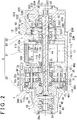
- FIG. 2 is a sectional view showing an example of the structure of the electric motor 11 and the driving force transmission apparatus 12 of the drive apparatus 1.
- the driving force transmission apparatus 12 has a hollow housing 2, a speed reduction mechanism 3, a rear differential 4, and a linkage mechanism 5.
- the housing 2 is fixed to the vehicle body 101.
- the speed reduction mechanism 3 reduces the speed of rotation output from the electric motor 11.
- the rear differential 4 distributes the torque output from the electric motor 11, after speed reduction by the speed reduction mechanism 3, to the rear axle shafts 106R, 106L while allowing differential rotations.
- the linkage mechanism 5 is able to cut off the connection between the rear axle shaft 106R and one of a pair of output members of the rear differential 4.
- the electric motor 11 is housed in the housing 2.
- the housing 2 has a tubular rotation force applying member 30 (described later), and also has a first housing element 20, a second housing element 21, a third housing element 22 and a fourth housing element 23.
- the rotation force applying member 30 constitutes the speed reduction mechanism 3.
- the first housing element 20 houses the rear differential 4.
- the second housing element 21 houses the electric motor 11.
- the third housing element 22 opens toward the second housing element 21 side.
- the fourth housing element 23 is interposed between the third housing element 22 and the second housing element 21.
- the first to fourth housing elements 20 to 23 are disposed along a rotation axis O 1 of the electric motor 11.
- axial direction the direction parallel to the rotation axis O 1
- the first housing element 20 is disposed at one side of the housing 2 in the axial direction (at the left side in FIG. 2 ).
- the first housing element 20 is formed of a stepped cylindrical member that has a large-diameter opening portion located on the second housing element 21 side, and a small-diameter opening portion located on the opposite side of the first housing element 20 from the large-diameter opening portion.
- the small-diameter opening portion of the first housing element 20 is formed as a shaft insertion hole 20a through which the rear axle shaft 106L is passed. Inside the shaft insertion hole 20a, there is disposed a seal member 24 that seals a space between an inner peripheral face of the small-diameter portion, which defines the shaft insertion hole 20a, and an outer peripheral face of the rear axle shaft 106L.
- the second housing element 21 is a single-piece member having a tubular portion 210 and an inner flange 211.
- the tubular portion 210 opens toward both sides in the axial direction.
- the inner flange 211 is formed at one opening portion of the tubular portion 210 (the opening portion on the first housing element 20 side), and protrudes inward from an inner face of the tubular portion 210.
- the third housing element 22 is disposed at the other side of the housing 2 in the axial direction (the right side in FIG. 2 ).
- the third housing element 22 is a single-piece member having a cylindrical portion 220 and a bottom portion 221.
- the cylindrical portion 220 opens toward the second housing element 21.
- the bottom portion 221 is formed at one end of the cylindrical portion 220.
- a cylindrical portion 222 which protrudes from the bottom portion 220 toward the electric motor 11 and to which a bearing is fitted, is formed integrally with the bottom portion 221 so as to surround the inner opening of the shaft insertion hole 22a.
- a seal member 25 that seals a space between an inner peripheral face of the bottom portion 221, which defines the shaft insertion hole 22a, and an outer peripheral face of the rear axle shaft 106R.
- the fourth housing element 23 is interposed between the second housing element 21 and the third housing element 22, and is fixed with a fitting bolt 230.
- the fourth housing element 23 is formed of an annular plate member having a predetermined thickness.
- a fitting hole 23a for fitting of the electric motor 50 provided as a drive source of the linkage mechanism 5 (described later).
- the fitting hole 23a extends through the fourth housing element 23 in its thickness direction.
- a stator 118a of a resolver 118 that detects the rotation angle of the electric motor 11 is fitted, via a fixture member 231, to an electric motor 11-side side face of the fourth housing element 23.
- the electric motor 11 includes a stator 110, a rotor 111 and a motor shaft 112.
- the stator 110 of the electric motor 11 is connected to the control unit 10, and is supplied with motor current from the control unit 10 to generate a magnetic field that rotates the rotor 111.
- the motor shaft 112 is fixed to an inner periphery of the rotor 111.
- the motor shaft 112 extends in the axial direction through a center portion of the inner flange 211 of the second housing element 21.
- the stator 110 is fixed to the inner flange 211 of the second housing element 21 with a bolt 113.
- the motor shaft 112 has a tubular shape, and has an insertion hole 112a at its center portion.
- the insertion hole 112a extends in the axial direction, and a first intermediate shaft 44 is passed through the insertion hole 112a.
- One axial end portion of the motor shaft 112 is supported by a bearing 114 disposed between the one end portion and a differential case 40 of the rear differential 4.
- the other axial end portion of the motor shaft 112 is supported by a bearing 115 disposed between the other end portion and the fourth housing element 23.
- An axial center portion of the motor shaft 112 is rotatably supported by the inner flange 211 of the second housing element 21 via a bearing 116 and a sleeve 117.
- An eccentric portion 112b and an eccentric portion 112c are formed integrally with the one end portion of the motor shaft 42.
- the eccentric portion 112b has an axis O 2 that is parallel to the rotation axis O 1 and is offset from the rotation axis O 1 by an eccentric amount ⁇ 1 .
- the eccentric portion 112b and the eccentric portion 112c are arranged so as to be next to each other along the rotation axis O 1 and apart from each other in the circumferential direction around the rotation axis O 1 at equal intervals (180°).
- a rotor 118b of the resolver 118 is fitted to the other end portion of the motor shaft 112 via a sleeve 119.
- the resolver 118 outputs, to the control unit 10, a signal corresponding to the rotation angle of the rotor 118b relative to the stator 118a.
- the control unit 10 is able to detect the rotational speed of the electric motor 11 (the rotational speed of the rotor 111 relative to the stator 110).
- FIG. 3 is an explanatory view showing the structure of the speed reduction mechanism 3 as viewed from the axial direction.
- the speed reduction mechanism 3 is formed as an involute-gear speed reduction mechanism with a small teeth number difference.
- the speed reduction mechanism 3 has the rotation force applying member 30, a pair of input members 31, 32, and a plurality of shaft-shaped output members 33.
- the speed reduction mechanism 3 is disposed between the rear differential 4 and the electric motor 11.
- the input member 31 is formed of an external gear that has a center hole 31a of which the central axis coincides with the axis O 2 .
- the input member 31 is supported at its inner periphery, which defines the center hole 31a, by an outer peripheral face of the eccentric portion 112b via a bearing 34.
- the input member 31 receives torque from the electric motor 11 via the eccentric portion 112b of the motor shaft 112 and the bearing 34, and makes circular motion (revolving motion about the rotation axis O 1 ) in the directions of the arrows m 1 , m 2 with the eccentric amount ⁇ .
- the input member 31 has a plurality of (six, in the present embodiment) pin insertion holes (through-holes) 31b that are arranged at equal intervals about the axis O 2 .
- the output members 33 are passed through the pin insertion holes 31b.
- a needle roller bearing 36 is disposed on an outer periphery of each output member 33.
- the hole diameter of each pin insertion holes 31b is set to a value that is larger than the outside diameter of each needle roller bearing 36.
- External teeth 31c having an involute tooth profile with a pitch circle of which the central axis coincides with the axis O 2 , are formed on an outer periphery of the input member 50.
- the input member 32 is formed of an external gear that has a center hole 32a of which the central axis coincides with the axis O' 2 , and that is symmetric in shape to the input member 31.
- the input member 32 is disposed so as to be closer to the electric motor 11 than the input member 31.
- the input member 32 is rotatably supported, at its inner periphery which defines the center hole 32a, by an outer peripheral face of the eccentric portion 112c via a bearing 35.
- the input member 32 makes circular motion (revolving motion about the rotation axis O 1 ) in the directions of the arrows m 1 , m 2 with the eccentric amount ⁇ , upon reception of motor torque from the electric motor 11.
- the input member 32 has a plurality of pin insertion holes 32b that are arranged at equal intervals about the axis O' 2 .
- the output members 33 are passed through the pin insertion holes 32b.
- a needle roller bearing 37 is disposed on an outer periphery of each output member 33.
- External teeth 32c having an involute tooth profile with a pitch circle of which the central axis coincides with the axis O' 2 , are formed on an outer periphery of the input member 32.
- the number of teeth Z 2 of the external teeth 32c is equal to the number of teeth Z 1 of the external teeth 31c of the input member 31.
- the rotation force applying member 30 is formed of an internal gear of which the central axis coincides with the rotation axis O 1 , is disposed between the first housing element 20 and the second housing element 21, and is fixed with bolts 300.
- the rotation force applying member 30 meshes with the input members 31, 32.
- the rotation force applying member 30 applies rotation force in the direction of arrows n 1 , n 2 to the input member 31 that receives motor torque from the electric motor 11 to revolve about the axis O 2 , and applies rotation force in the directions of arrows l 1 , l 2 to the input member 32 that receives motor torque from the electric motor 11 to revolve about the axis O' 2 .
- An inner peripheral face of the rotation force applying member 30 has internal teeth 30c that mesh with the external teeth 31c of the input member 31 and the external teeth 32c of the input member 32.
- the output members 33 are disposed at equal intervals about the rotation axis O 1 .
- the output members 33 extend through the pin insertion holes 31b of the input member 31 and the pin insertion holes 32b of the input member 32.
- One end of each output member 33 is fixed to a first flange 401 of the differential case 40 with a nut 331, and the other end thereof is fixed to a second flange 402 with a nut 331.
- the output members 33 receive, from the input members 31, 32, rotation forces applied by the rotation force applying member 30, and output the rotation force to the differential case 40 as torque of the differential case 40.
- the rear differential 4 is formed of a bevel gear differential gear mechanism that includes the differential case 40, a pinion shaft 41, a pair of pinion gears 42, and side gears 43.
- the pinion shaft 41 is fixed to the differential case 40.
- the pinion gears 42 are rotatably supported by the pinion shaft 41.
- the side gears 43 are a pair of output members that mesh with the pinion gears 42. Due to this structure, the rear differential 4 transmits torque output from the electric motor 11 after speed reduction by the speed reduction mechanism 3, to the right and left rear wheels 107R, 107L while allowing differential rotations.
- the differential case 40 is supported so as to be rotatable relative to the housing 2, by a bearing 201 disposed between the differential case 40 and the first housing element 20 and a bearing 301 disposed between the differential case 40 and the rotation force applying member 30.
- the disc-shaped first flange 401 is formed integrally with one axial end of the differential case 40.
- the disc-shaped second flange 402 is disposed so as to be opposed to the first flange 401.
- the first flange 401 and the second flange 402 are connected to each other by the output members 33 of the speed reduction mechanism 3 so as to be non-rotatable relative to each other and immovable in the axial direction.
- the left rear wheel 107L-side side gear 43 is connected to the left rear wheel 107L-side rear axle shaft 106L so as to be non-rotatable relative to the rear axle shaft 106L. Furthermore, out of the side gears 43, the right rear wheel 107R-side side gear 43 is connected to the first intermediate shaft 44 so as to be non-rotatable relative to the first intermediate shaft 44.
- the linkage mechanism 5 includes the electric motor 50, a cylindrical sleeve 51 and a gear transmission mechanism 52.
- the sleeve 51 is advanced and retracted in the axial direction by driving force generated by the electric motor 50.
- the gear transmission mechanism 52 converts the driving force output from the electric motor 50 into movement force in the axial direction, and transmits the force to the sleeve 51.
- the electric motor 50 is controlled by the control unit 10 (shown in FIG. 1 ), and the rotation direction of the electric motor 50 is changed according to the direction of the current supplied from the control unit 10.
- the linkage mechanism 5 connects the first intermediate shaft 44 to a second intermediate shaft 45 that is rotatable relative to the first intermediate shaft 44 on the same axis as the first intermediate shaft 44, or disconnects the first intermediate shaft 44 from the second intermediate shaft 45.
- One end portion of the first intermediate shaft 44 is connected to the right rear wheel 107R-side side gear 43 of the rear differential 4.
- the other end portion of the first intermediate shaft 44 is supported by a bearing 232 that is disposed between the other end portion and the fourth housing element 23.
- An axial center portion of the first intermediate shaft 44 is housed in the insertion hole 112a of the motor shaft 112.
- the second intermediate shaft 45 is disposed at a position closer to the shaft insertion hole 22a than the first intermediate shaft 44 in a direction along the rotation axis O 1 .
- the second intermediate shaft 45 is supported by two bearing 223, 224 both of which are fitted to an inner face of the cylindrical portion 222 of the third housing element 22.
- the bearing 223 and the bearing 224 are arranged next to each other in the axial direction with an annular spacer 225 interposed therebetween, and are prevented from being removed by a stopper member 226.
- the stopper member 226 is fixed to an end face of the cylindrical portion 222 with bolts 227.
- a first gear 521 formed of a cylindrical screw gear is fitted to a motor shaft 501 of the electric motor 50.
- the first gear 521 is in mesh with a second gear 522 formed of a rectangular parallelepiped rack.
- the second gear 522 is fixed to a side face of an annular movement force transmission member 523.
- a plurality of pillar-shaped guide members 524 is fixed to the movement force transmission member 523.
- the guide members 524 extend in the axial direction so as to be perpendicular to the side face of the movement force transmission member 523.
- Distal end portions of the guide members 524 are movably housed in guide holes 23b respectively formed at multiple locations in the fourth housing element 23.
- a radially inner end portion of the movement force transmission member 523 is fitted in an annular groove 51a that is formed in an outer peripheral face of the sleeve 51.
- the first gear 521, the second gear 522, the movement force transmission member 523 and the guide members 524 constitute the gear transmission mechanism 52.
- the gear transmission mechanism 52 converts the torque of the motor shaft 501 into movement force that moves the movement force transmission member 523 in the axial direction, due to the mesh between the first gear 521 and the second gear 522.
- the movement force transmission member 523 that has received the movement force is guided in the axial direction to advance and retract the sleeve 51 in the axial direction, as the guide members 524 move in the guide holes 23b.
- a plurality of spline teeth 510 is formed on an inner peripheral face of the sleeve 51. Furthermore, a plurality of spline teeth 440 is formed on an outer peripheral face of a second intermediate shaft 45-side end portion of the first intermediate shaft 44. In addition, a plurality of spline teeth 450 is formed on an outer peripheral face of a first intermediate shaft 44-side end portion of the second intermediate shaft 45.
- the sleeve 51 advances and retracts between a first position (shown by a long dashed double-short dashed line in FIG. 2 ), at which the spline teeth 510 mesh with the spline teeth 440 of the first intermediate shaft 44 but do not mesh with the spline teeth 450 of the second intermediate shaft 45, and a second position (shown by a continuous line in FIG. 2 ), at which the spline teeth 510 mesh with both the spline teeth 440 and the spline teeth 450.
- a first position shown by a long dashed double-short dashed line in FIG. 2
- a second position shown by a continuous line in FIG. 2
- the linkage mechanism 5 is configured such that the sleeve 51 moves from the first position to the second position when the electric motor 50 rotates in the forward rotation direction, and such that the sleeve 51 moves from the second position to the first position when the electric motor 50 rotates in the reverse rotation direction.
- the first intermediate shaft 44 and the second intermediate shaft 45 are connected to each other so as to be non-rotatable relative to each other.
- the first intermediate shaft 44 and the second intermediate shaft 45 are disconnected from each other.
- the linkage mechanism 5 is able to carry out switchover between a connected state where the first intermediate shaft 44 (a first rotary member on the electric motor 11 side) and the second intermediate shaft 45 (a second rotary member on the wheel side) are connected to each other so as to be non-rotatable relative to each other to transmit torque from the electric motor 11 to the wheel (the right rear wheel 107R), and a disconnected state where the first intermediate shaft 44 and the second intermediate shaft 45 are disconnected from each other.
- FIG. 4A and FIG. 4B are schematic diagrams showing the states of mesh between the spline teeth 510 of the sleeve 51, and the spline teeth 440 of the first intermediate shaft 44 and the spline teeth 450 of the second intermediate shaft 45.
- FIG. 4A shows the state where the sleeve 51 is at the first position.
- FIG. 4B shows the state where the sleeve 51 is at the second position.
- the spline teeth 510 which serve as protrusion portions, mesh with recessed portions 440a formed between the spline teeth 440 of the first intermediate shaft 44.
- the spline teeth 510 do not mesh with recessed portions 450a formed between the spline teeth 450 of the second intermediate shaft 45, so that the first intermediate shaft 44 and the second intermediate shaft 45 are rotatable relative to each other.
- the linkage mechanism 5 is formed as a dog clutch that connects the first intermediate shaft 44 and the second intermediate shaft 45 to each other by the meshing the spline teeth 510 of the sleeve 51 with the recessed portions 450a of the second intermediate shaft 45.
- the movement of the sleeve 51 may be hindered by the force of friction that occurs at regions of contact between side faces of the spline teeth 510 of the sleeve 51 and side faces of the spline teeth 450 of the second intermediate shaft 45. In such a case, it is not possible to switch the driving force transmission apparatus 12 from the connected state to the disconnected state.
- Examples of the case where torque is transmitted between the sleeve 51 and the second intermediate shaft 45 include the case where the four-wheel drive vehicle 100 is travelling using the driving force of the right and left front wheels 104R, 104L or coasting, with no motor current being supplied to the electric motor 11, and the case where the rotation output from the electric motor 11 is reduced in speed by the speed reduction mechanism 3 and then transmitted to the second intermediate shaft 45 via the rear differential 4 and the first intermediate shaft 44.
- torque is transmitted from the second intermediate shaft 45 to the sleeve 51.
- torque is transmitted from the sleeve 51 to the second intermediate shaft 45.
- FIG. 5A and FIG. 5B are partially enlarged views of sections of the sleeve 51 and the second intermediate shaft 45 on a plane orthogonal to the axial direction.
- FIG. 5A shows a state where torque is being transmitted from the second intermediate shaft 45 to the sleeve 51.
- FIG. 5B shows a state where torque is being transmitted from the sleeve 51 to the second intermediate shaft 45.
- the rotation direction of the sleeve 51 and the rotation direction of the second intermediate shaft 45 are both the direction shown by an arrow A.
- first side faces 510b of the spline teeth 510 and first side faces 450b of the spline teeth 450 contact each other, so that torque is transmitted at regions of contact between the first side faces 510b and the first side faces 450b, as shown in FIG. 5A .
- second side faces 510c of the spline teeth 510 and second side faces 450c of the spline teeth 450 contact each other, so that torque is transmitted at regions of contact between the second side faces 510c and the second side faces 450c, as shown in FIG. 5B .
- the side faces of the spline teeth mean surfaces that intersect with circumferential directions about the rotation axis O 1 .
- switchover from the connected state to the disconnected state is carried out with the force of friction between the spline teeth 510 and the spline teeth 450 reduced.
- the movement of the sleeve 51 by the driving force generated by the electric motor 50 in the linkage mechanism 5 is facilitated.
- the control unit 10 reduces the torque that is generated by the electric motor 11, in a drive state where torque output from the electric motor 11 is transmitted from the first intermediate shaft 44 (sleeve 51) to the second intermediate shaft 45. In the state where the torque that is generated by the electric motor 11 has been reduced, the control unit 10 controls the linkage mechanism 5 to switch the driving force transmission apparatus 12 from the connected state to the disconnected state.
- FIG. 6 is the flowchart showing an example of a process that is executed by the control unit 10 to carry out switchover from the four-wheel-drive mode to the two-wheel-drive mode.
- the control unit 10 determines whether to switch the drive mode to the two-wheel-drive mode (step S1). The determination may be made, for example, on the basis of whether the difference between the average rotational speed of the right and left front wheels 104R, 104L and the average rotational speed of the right and left rear wheels 107R, 107L is less than or equal to a predetermined value. Alternatively, the determination may be made on the basis of the amount of operation of the accelerator pedal performed by a driver, the vehicle speed or the steering angle. More specifically, the control unit 10 may determine that the vehicle should be switched to the two-wheel-drive mode, for example, in a steady travelling state during which the vehicle speed is substantially constant and the vehicle is travelling straight.
- step S2 determines whether the driving force transmission apparatus 12 is in the drive state (step S2).
- the drive state is a state where torque output from the electric motor 11 is transmitted from the first intermediate shaft 44 to the second intermediate shaft 45 via the sleeve 51.
- the control unit 10 determines whether the driving force transmission apparatus 12 is in the drive state, on the basis of, for example, the motor current for the electric motor 11 and the rotational speed of the electric motor 11 detected by the resolver 118. That is, the control unit 10 determines that the driving force transmission apparatus 12 is in the drive state, for example, when the electric motor 11 is being supplied with a current that is larger than the current that is needed in order to rotate the first intermediate shaft 44 at the rotational speed detected by the resolver 118 during the state where the first intermediate shaft 44 and the second intermediate shaft 45 are not connected to each other.
- step S2 If it is determined in step S2 that the driving force transmission apparatus 12 is not in the drive state (NO in S2), that is, if the driving force transmission apparatus 12 is in a coasting state where the electric motor 11 is being rotated by turning force of the right and left rear wheels 107R, 107L, which is generated as the four-wheel drive vehicle 100 travels, the control unit 10 supplies the electric motor 11 with motor current so as to rotate the first intermediate shaft 44 (step S3). After that, the determination in step S2 is carried out again. Until the drive state is achieved, the control unit 10 continues supplying motor current to the electric motor 11 so as to increase the torque that is output from the electric motor 11.
- step S2 If it is determined in step S2 that the driving force transmission apparatus 12 is in the drive state (YES in S2), the control unit 10 supplies motor current to the electric motor 50 of the linkage mechanism 5 (step S4).
- the sleeve 51 is urged in such a direction as to move from the second position to the first position.
- the sleeve 51 may fail to move to the first position, due to force of friction between the spline teeth 510 and the spline teeth 450. That is, in some cases, even if the electric motor 50 is supplied with motor current, the sleeve 51 does not move to the first position.
- control unit 10 reduces the motor current that is supplied to the electric motor 11, to a motor current that is smaller than the motor current supplied to the electric motor 11 when it is determined in step S2 that the driving force transmission apparatus 12 is in the drive state (step S5). Note that, the execution sequence of step S4 and step S5 may be reversed. That is, after the motor current that is supplied to the electric motor 11 is reduced, motor current may be supplied to the electric motor 50 of the linkage mechanism 5.
- control unit 10 determines whether a predetermined time has elapsed since the reduction of the motor current that is supplied to the electric motor 11 (step S6). If the predetermined time has elapsed (YES in S6), the control unit 10 stops supplying the motor current to the electric motor 50 (step S7), and then determines whether the first intermediate shaft 44 and the second intermediate shaft 45 have been disconnected from each other, that is, whether the switchover from the connected state to the disconnected state has been established (step S8).
- predetermined time in step S6 is set to a time that is longer than the length of time that is required for the rotational speed of the first intermediate shaft 44 to become lower than the rotational speed of the second intermediate shaft 45 by a predetermined amount in the case where the switchover to the disconnected state has been normally carried out. Furthermore, whether the switchover from the connected state to the disconnected state has been established can be determined, for example, on the basis of whether the difference between the rotational speed of the first intermediate shaft 44 and the rotational speed of the second intermediate shaft 45 is greater than or equal to a predetermined value.
- control unit 10 can calculate the rotational speed of the first intermediate shaft 44 on the basis of the rotational speed of the electric motor 11 detected by the resolver 118, while taking into account, for example, the speed reduction ratio ⁇ of the speed reduction mechanism 3. Furthermore, the rotational speed of the second intermediate shaft 45 can be detected on the basis of the rotational speed of the right rear wheel 107R.
- step S8 determines in step S8 that the switchover to the disconnected state has been established (YES in S8), the control unit 10 ends the process of the flowchart shown in FIG. 6 . On the other hand, if it is determined in step S8 that the switchover to the disconnected state has failed to be established (NO in S8), the control unit 10 executes again the process in step S2 and the following processes.
- control unit 10 executes again the process of bringing about the drive state where torque output from the electric motor 11 is transmitted from the first intermediate shaft 44 to the second intermediate shaft 45, reducing the torque that is output from the electric motor 11, and then controlling the linkage mechanism 5 so as to switch the driving force transmission apparatus 12 from the connected state to the disconnected state while the torque of the electric motor 11 has been reduced.
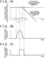
- FIG. 7A to FIG. 7C are time charts illustrating the case where, at the time of switchover from the four-wheel-drive mode to the two-wheel-drive mode, the switchover from the connected state where the first intermediate shaft 44 and the second intermediate shaft 45 are connected to each other, to the connected state is established on the first attempt.
- FIG. 7A shows changes in the rotational speeds of the first intermediate shaft 44 and the second intermediate shaft 45.
- FIG. 7B shows changes in the motor current for the electric motor 11.
- FIG. 7C shows changes in the motor current for the electric motor 50.
- the abscissa axes show time. Note that, in the following description, the processes executed by the control unit 10 at respective time points will be indicated by step numbers of the flowchart of FIG. 6 mentioned in parentheses.
- the motor current for the electric motor 11 is zero, the first intermediate shaft 44 and the second intermediate shaft 45 are connected to each other so as to be non-rotatable relative to each other, and the electric motor 11 is rotated by the turning forces of the right and left rear wheels 107R, 107L.
- step S2 determines whether the driving force transmission apparatus 12 is in the drive state (step S2).
- the vehicle 100 is in the coasting state where the electric motor 11 is rotated by the turning forces of the right and left rear wheels 107R, 107L. Therefore, a negative determination is made (NO in S2), so that the control unit 10 starts supplying motor current to the electric motor 11 (step S3). After that, the motor current for the electric motor 11 increases.
- control unit 10 supplies motor current to the electric motor 50 of the linkage mechanism 5 (step S4) and, at time t 3 , reduces the motor current for the electric motor 11 (step S5).
- the torque output from the electric motor 11 decreases and therefore the surface pressure at the regions of contact between the second side faces 510c of the spline teeth 510 and the second side faces 450c of the spline teeth 450a becomes lower.
- the force of friction acting between the spline teeth 510 and the spline teeth 450 decreases. Therefore, the resistance force that hinders the movement of the sleeve 51 becomes smaller, and therefore the sleeve 51 moves more easily from the second position toward to the first position.
- step S7 the control unit 10 stops supplying motor current to the electric motor 50 of the linkage mechanism 5 (step S7), and determines whether the switchover to the disconnected state has been established (step S8).
- control unit 10 determines that the switchover to the disconnected state has been established (YES in S8), and then ends the process.
- FIG. 8A to FIG. 8C are time charts illustrating the case where, at the time of switchover from the four-wheel-drive mode to the two-wheel-drive mode, the switchover from the connected state where the first intermediate shaft 44 and the second intermediate shaft 45 are connected to each other to the disconnected state fails to be established on the first attempt, and then is successfully established on the second attempt.
- FIG. 8A shows changes in the rotational speeds of the first intermediate shaft 44 and the second intermediate shaft 45.
- FIG. 8B shows changes in the motor current for the electric motor 11.
- FIG. 8C shows changes in the motor current for the electric motor 50.
- control unit 10 determines at time t 5 that the switchover to the disconnected state has resulted in establishment failure (NO in S8), the control unit 10 starts again, at time t 6 , the supply of motor current to the electric motor 11 (step S3) so as to increase the torque output from the electric motor 11.
- the control unit 10 supplies motor current to the electric motor 50 of the linkage mechanism 5 (step S4) and, at time t 8 , reduces the motor current for the electric motor 11 (step S5).
- the rate of reduction in the motor current for the electric motor 11 (the amount of reduction in the motor current per unit time) in this case may be lower than the rate of reduction in the motor current during the period from time t 3 to time t 5 . That is, the motor current may be reduced more moderately than in the first reduction period.
- step S7 If the sleeve 51 moves from the second position to the first position and therefore the first intermediate shaft 44 and the second intermediate shaft 45 are disconnected from each other at time t 9 , the rotational speed of the first intermediate shaft 44 becomes lower than the rotational speed of the second intermediate shaft 45 and gradually decreases.
- the control unit 10 stops supplying motor current to the electric motor 50 of the linkage mechanism 5 at time t 10 (step S7), at which the predetermined time elapses following time t8, and then determines whether the switchover to the disconnected state has been established (step S8).
- step S7 the predetermined time elapses following time t8
- step S8 because there is a difference between the rotational speed of the first intermediate shaft 44 and the rotational speed of the second intermediate shaft 45 at time t 10 , the control unit 10 determines in step S8 that the switchover to the disconnected state has been established (YES in S8), and then ends the process.
- the sleeve 51 is moved from the second position to the first position while the torque output from the electric motor 11 has been made lower than the torque in the drive state.
- the driving force of the electric motor 50 of the linkage mechanism 5, which is required to move the sleeve 51 becomes lower than that in the case where the sleeve 51 is moved while the drive state is maintained, or while the motor current for the electric motor 11 is zero.
- the driving force transmission apparatus 12 disconnects the first intermediate shaft 44 connected to the side gear 43 of the rear differential 4 and the second intermediate shaft 45 connected to the rear axle shaft 106R from each other.
- the four-wheel drive vehicle 100 is switched to the two-wheel-drive mode. Therefore, the linkage mechanism 5 is made more compact than that, for example, in the case where the flange 401 of the differential case 40 of the rear differential 4 and the main portion of the differential case 40 (a portion that houses the pinions 42 and the side gears 43) are disconnected from each other.
Landscapes
- Engineering & Computer Science (AREA)
- Chemical & Material Sciences (AREA)
- Combustion & Propulsion (AREA)
- Transportation (AREA)
- Mechanical Engineering (AREA)
- Automation & Control Theory (AREA)
- Arrangement And Driving Of Transmission Devices (AREA)
- Electric Propulsion And Braking For Vehicles (AREA)
- Hybrid Electric Vehicles (AREA)
- Retarders (AREA)
- Mechanical Operated Clutches (AREA)
- Hydraulic Clutches, Magnetic Clutches, Fluid Clutches, And Fluid Joints (AREA)
- Control Of Electric Motors In General (AREA)
- Arrangement And Mounting Of Devices That Control Transmission Of Motive Force (AREA)
Claims (3)
- Appareil d'entraînement de véhicule (1) comprenant :un moteur (11) qui génère un couple utilisé en tant que force d'entraînement pour un véhicule ;un appareil de transmission de force d'entraînement (12) qui transmet le couple produit par le moteur à une roue (107R) ; etune unité de commande (10) qui commande le moteur et l'appareil de transmission de force d'entraînement, dans lequel :l'appareil de transmission de force d'entraînement comprend un mécanisme de liaison (5) pouvant réaliser la commutation entre un état raccordé dans lequel un premier élément rotatif (44) du côté du moteur et un second élément rotatif (45) du côté de la roue sont raccordés entre eux afin de ne pas pouvoir tourner l'un par rapport à l'autre pour transmettre le couple produit par le moteur à la roue, et un état déconnecté dans lequel le premier élément rotatif et le second élément rotatif sont déconnectés l'un de l'autre ;lorsque l'on commute l'appareil de transmission de force d'entraînement de l'état raccordé à l'état déconnecté, l'unité de commande est configurée pour :déterminer si l'appareil de transmission de force d'entraînement est dans un état d'entraînement dans lequel le couple produit par le moteur est transmis du premier élément rotatif au second élément rotatif ou pas, et si l'appareil de transmission de force d'entraînement n'est pas à l'état d'entraînement, pour fournir le courant de moteur au moteur afin d'établir l'état d'entraînement de l'appareil de transmission de force d'entraînement,fournir ensuite le courant de moteur à un moteur de mécanisme de liaison afin d'actionner le mécanisme de liaison pour commuter l'appareil de transmission de force d'entraînement de l'état raccordé à l'état déconnecté,réduire ensuite le couple qui est généré par le moteur tout en fournissant le courant de moteur au moteur de mécanisme de liaison,déterminer si un temps prédéterminé s'est écoulé depuis la réduction du couple qui est généré par le moteur, etsi le temps prédéterminé s'est écoulé, arrêter de fournir le courant de moteur au moteur de mécanisme de liaison.
- Appareil d'entraînement de véhicule selon la revendication 1, dans lequel :le mécanisme de liaison est un embrayage à griffes qui raccorde le premier élément rotatif et le second élément rotatif entre eux par engrènement d'une partie évidée (440b ; 450b) formée au niveau de l'un parmi le premier élément rotatif et le second élément rotatif avec une partie de saillie (510) formée au niveau de l'autre parmi le premier élément rotatif et le second élément rotatif ; etlorsque la commutation de l'état raccordé à l'état déconnecté par le biais de la commande du mécanisme de liaison n'est pas établie, l'unité de commande réduit le couple qui est généré par le moteur après avoir occasionné l'état d'entraînement dans lequel le couple produit par le moteur est transmis du premier élément rotatif au second élément rotatif à nouveau, et commute l'appareil de transmission de force d'entraînement de l'état raccordé à l'état déconnecté en commandant le mécanisme de liaison alors que le couple qui est généré par le moteur a été réduit.
- Appareil d'entraînement de véhicule selon la revendication 1 ou 2, dans lequel :l'appareil de transmission de force d'entraînement comprend un mécanisme d'engrenage différentiel (4) qui transmet le couple produit par le moteur à une roue droite (107R) et à une roue gauche (107L) du véhicule tout en permettant des mouvements différentiels de la roue droite et de la roue gauche ;le premier élément rotatif est raccordé à un élément de sortie parmi une paire d'éléments de sortie (43) du mécanisme d'engrenage différentiel ; etle second élément rotatif est raccordé à l'une parmi la roue droite et la roue gauche, l'une des roues étant une roue à laquelle le couple produit par le moteur est transmis via le un élément de sortie.
Applications Claiming Priority (1)
| Application Number | Priority Date | Filing Date | Title |
|---|---|---|---|
| JP2012195212A JP6069973B2 (ja) | 2012-09-05 | 2012-09-05 | 車両用駆動装置 |
Publications (3)
| Publication Number | Publication Date |
|---|---|
| EP2705995A2 EP2705995A2 (fr) | 2014-03-12 |
| EP2705995A3 EP2705995A3 (fr) | 2017-12-13 |
| EP2705995B1 true EP2705995B1 (fr) | 2020-12-16 |
Family
ID=49165515
Family Applications (1)
| Application Number | Title | Priority Date | Filing Date |
|---|---|---|---|
| EP13182733.9A Active EP2705995B1 (fr) | 2012-09-05 | 2013-09-03 | Appareil de commande de véhicule |
Country Status (4)
| Country | Link |
|---|---|
| US (1) | US8961367B2 (fr) |
| EP (1) | EP2705995B1 (fr) |
| JP (1) | JP6069973B2 (fr) |
| CN (1) | CN103671817B (fr) |
Families Citing this family (6)
| Publication number | Priority date | Publication date | Assignee | Title |
|---|---|---|---|---|
| JP6245185B2 (ja) * | 2015-01-16 | 2017-12-13 | トヨタ自動車株式会社 | ハイブリッド車両の駆動装置 |
| CN110281698B (zh) * | 2019-06-18 | 2020-12-04 | 一汽解放汽车有限公司 | 一种驱动桥总成 |
| JP7348764B2 (ja) * | 2019-07-11 | 2023-09-21 | 住友重機械工業株式会社 | 車輪駆動装置、車輪駆動装置のメンテナンス方法 |
| KR20240108504A (ko) * | 2022-07-28 | 2024-07-09 | 저장 지커 인텔리전트 테크놀로지 씨오., 엘티디 | 전기차 및 그 모터 제어 방법, 장치 및 저장매체 |
| EP4421355A4 (fr) * | 2022-12-08 | 2025-01-29 | Zhejiang Zeekr Intelligent Technology Co., Ltd. | Procédé et appareil de commande de changement de vitesse automatique, dispositif et support de stockage |
| CN118775445A (zh) * | 2024-07-11 | 2024-10-15 | 中国船舶集团有限公司第七0三研究所 | 一种用于动态接合的齿式离合器 |
Family Cites Families (20)
| Publication number | Priority date | Publication date | Assignee | Title |
|---|---|---|---|---|
| US4625584A (en) * | 1984-11-05 | 1986-12-02 | Toyota Jidosha Kabushiki Kaisha | Split axle drive mechanism for part-time four-wheel drive vehicle |
| JPH11243608A (ja) * | 1998-02-24 | 1999-09-07 | Honda Motor Co Ltd | 車両用電動式駆動装置 |
| JP3823728B2 (ja) * | 1998-12-03 | 2006-09-20 | 株式会社日立製作所 | 自動変速システム |
| US7140460B2 (en) * | 2002-08-26 | 2006-11-28 | Nissan Motor Co., Ltd. | Vehicle driving force control apparatus |
| JP3536845B2 (ja) * | 2002-10-03 | 2004-06-14 | 日産自動車株式会社 | 車両の駆動力制御装置 |
| JP3610970B2 (ja) * | 2002-08-30 | 2005-01-19 | 日産自動車株式会社 | 四輪駆動車両の駆動力制御装置 |
| JP4228789B2 (ja) * | 2003-06-18 | 2009-02-25 | トヨタ自動車株式会社 | 車両の制御装置 |
| DE102004026039A1 (de) * | 2004-05-27 | 2005-12-15 | Linde Ag | Antriebsachse mit einem durch den Elektromotor eines Fahrantriebs antreibbaren Arbeitsantrieb |
| JP4959354B2 (ja) * | 2007-01-29 | 2012-06-20 | 本田技研工業株式会社 | 車両駆動装置の油圧回路 |
| DE602008001806D1 (de) | 2007-01-25 | 2010-09-02 | Honda Motor Co Ltd | Fahrzeugantriebsvorrichtung und hydraulische Schaltung dafür |
| JP2008296778A (ja) * | 2007-05-31 | 2008-12-11 | Toyota Motor Corp | 連結装置、変速機およびそれを備えた動力出力装置、ならびに連結装置の制御方法 |
| JP4410279B2 (ja) * | 2007-11-22 | 2010-02-03 | 三菱電機株式会社 | 自動変速装置の制御装置及び制御方法 |
| JP5253068B2 (ja) * | 2008-09-29 | 2013-07-31 | 本田技研工業株式会社 | 変速制御装置 |
| KR101563389B1 (ko) * | 2008-11-07 | 2015-10-26 | 마그나 파워트레인 유에스에이, 인크. | 전기 구동 2단-변속 트랜스액슬 |
| FR2954441B1 (fr) * | 2009-12-17 | 2012-03-09 | Peugeot Citroen Automobiles Sa | Procede et systeme d'accouplement d'une machine electrique sur un train roulant de vehicule, notamment d'un vehicule automobile hybride |
| FR2954254B1 (fr) * | 2009-12-17 | 2012-03-09 | Peugeot Citroen Automobiles Sa | Procede et systeme de desaccouplement d'une machine electrique sur un train roulant de vehicule, notamment d'un vehicule automobile hybride |
| JP5727729B2 (ja) * | 2010-07-20 | 2015-06-03 | 川崎重工業株式会社 | 車両の制御装置 |
| JP2012030727A (ja) * | 2010-07-30 | 2012-02-16 | Toyota Motor Corp | 車両用動力伝達装置の制御装置 |
| US8523738B2 (en) * | 2011-01-21 | 2013-09-03 | Dana Heavy Vehicle Systems Group, Llc | Method of shifting a tandem drive axle having an inter-axle differential |
| US8989930B2 (en) * | 2011-06-17 | 2015-03-24 | GM Global Technology Operations LLC | Method and apparatus for controlling an engine disconnect clutch in a powertrain system |
-
2012
- 2012-09-05 JP JP2012195212A patent/JP6069973B2/ja active Active
-
2013
- 2013-08-29 US US14/013,401 patent/US8961367B2/en active Active
- 2013-09-03 CN CN201310394981.8A patent/CN103671817B/zh active Active
- 2013-09-03 EP EP13182733.9A patent/EP2705995B1/fr active Active
Non-Patent Citations (1)
| Title |
|---|
| None * |
Also Published As
| Publication number | Publication date |
|---|---|
| JP2014051998A (ja) | 2014-03-20 |
| US8961367B2 (en) | 2015-02-24 |
| US20140066252A1 (en) | 2014-03-06 |
| EP2705995A2 (fr) | 2014-03-12 |
| JP6069973B2 (ja) | 2017-02-01 |
| EP2705995A3 (fr) | 2017-12-13 |
| CN103671817A (zh) | 2014-03-26 |
| CN103671817B (zh) | 2018-01-02 |
Similar Documents
| Publication | Publication Date | Title |
|---|---|---|
| EP2705995B1 (fr) | Appareil de commande de véhicule | |
| EP1985520B1 (fr) | Dispositif de direction à rapport de transmission variable | |
| EP2460683B1 (fr) | Dispositif de commande de la propulsion pour véhicule | |
| JP5919900B2 (ja) | ステアリング装置 | |
| US20200189538A1 (en) | Vehicle drive system | |
| EP3421282A1 (fr) | Dispositif de transmission d'alimentation véhiculaire | |
| JP4811595B2 (ja) | 車両用操舵装置 | |
| WO2017051719A1 (fr) | Véhicule à entraînement à double moteur | |
| WO2013146484A1 (fr) | Dispositif d'entraînement pour véhicule | |
| EP2705966B1 (fr) | Appareil de commande de véhicule | |
| US10808775B2 (en) | Torque limiter | |
| JP4484038B2 (ja) | 車両用操舵装置 | |
| US11421770B2 (en) | Power transmission mechanism | |
| JP5948109B2 (ja) | 車両用駆動装置 | |
| US11293524B2 (en) | Vehicle drive device | |
| JP2012158311A (ja) | 車両用駆動操舵アクチュエータ | |
| CN109804181B (zh) | 驱动源控制装置和具有该驱动源控制装置的车辆 | |
| JP2024126394A (ja) | 4輪駆動車 | |
| JP4626747B2 (ja) | トルク配分制御装置 | |
| JP6167038B2 (ja) | 駆動装置 | |
| JP2015127177A (ja) | 車両 | |
| JP2008014354A (ja) | 車両用操舵装置 |
Legal Events
| Date | Code | Title | Description |
|---|---|---|---|
| PUAI | Public reference made under article 153(3) epc to a published international application that has entered the european phase |
Free format text: ORIGINAL CODE: 0009012 |
|
| AK | Designated contracting states |
Kind code of ref document: A2 Designated state(s): AL AT BE BG CH CY CZ DE DK EE ES FI FR GB GR HR HU IE IS IT LI LT LU LV MC MK MT NL NO PL PT RO RS SE SI SK SM TR |
|
| AX | Request for extension of the european patent |
Extension state: BA ME |
|
| PUAL | Search report despatched |
Free format text: ORIGINAL CODE: 0009013 |
|
| AK | Designated contracting states |
Kind code of ref document: A3 Designated state(s): AL AT BE BG CH CY CZ DE DK EE ES FI FR GB GR HR HU IE IS IT LI LT LU LV MC MK MT NL NO PL PT RO RS SE SI SK SM TR |
|
| AX | Request for extension of the european patent |
Extension state: BA ME |
|
| RIC1 | Information provided on ipc code assigned before grant |
Ipc: B60W 10/08 20060101ALI20171103BHEP Ipc: B60K 6/48 20071001ALI20171103BHEP Ipc: B60W 10/06 20060101ALI20171103BHEP Ipc: B60W 10/11 20120101ALI20171103BHEP Ipc: B60K 6/52 20071001ALI20171103BHEP Ipc: B60W 10/02 20060101AFI20171103BHEP |
|
| STAA | Information on the status of an ep patent application or granted ep patent |
Free format text: STATUS: REQUEST FOR EXAMINATION WAS MADE |
|
| 17P | Request for examination filed |
Effective date: 20180504 |
|
| RBV | Designated contracting states (corrected) |
Designated state(s): AL AT BE BG CH CY CZ DE DK EE ES FI FR GB GR HR HU IE IS IT LI LT LU LV MC MK MT NL NO PL PT RO RS SE SI SK SM TR |
|
| STAA | Information on the status of an ep patent application or granted ep patent |
Free format text: STATUS: EXAMINATION IS IN PROGRESS |
|
| 17Q | First examination report despatched |
Effective date: 20181016 |
|
| RIC1 | Information provided on ipc code assigned before grant |
Ipc: B60K 6/48 20071001ALI20171103BHEP Ipc: B60K 6/52 20071001ALI20171103BHEP Ipc: B60W 10/02 20060101AFI20171103BHEP Ipc: B60W 10/06 20060101ALI20171103BHEP Ipc: B60W 10/08 20060101ALI20171103BHEP Ipc: B60W 10/11 20120101ALI20171103BHEP |
|
| REG | Reference to a national code |
Ref country code: DE Ref legal event code: R079 Ref document number: 602013074719 Country of ref document: DE Free format text: PREVIOUS MAIN CLASS: B60W0010020000 Ipc: B60W0020400000 |
|
| GRAP | Despatch of communication of intention to grant a patent |
Free format text: ORIGINAL CODE: EPIDOSNIGR1 |
|
| STAA | Information on the status of an ep patent application or granted ep patent |
Free format text: STATUS: GRANT OF PATENT IS INTENDED |
|
| RIC1 | Information provided on ipc code assigned before grant |
Ipc: B60W 10/08 20060101ALI20200615BHEP Ipc: B60K 6/48 20071001ALI20200615BHEP Ipc: B60W 20/40 20160101AFI20200615BHEP Ipc: B60K 6/52 20071001ALI20200615BHEP Ipc: B60W 10/02 20060101ALI20200615BHEP |
|
| INTG | Intention to grant announced |
Effective date: 20200630 |
|
| GRAS | Grant fee paid |
Free format text: ORIGINAL CODE: EPIDOSNIGR3 |
|
| GRAA | (expected) grant |
Free format text: ORIGINAL CODE: 0009210 |
|
| STAA | Information on the status of an ep patent application or granted ep patent |
Free format text: STATUS: THE PATENT HAS BEEN GRANTED |
|
| AK | Designated contracting states |
Kind code of ref document: B1 Designated state(s): AL AT BE BG CH CY CZ DE DK EE ES FI FR GB GR HR HU IE IS IT LI LT LU LV MC MK MT NL NO PL PT RO RS SE SI SK SM TR |
|
| REG | Reference to a national code |
Ref country code: GB Ref legal event code: FG4D |
|
| REG | Reference to a national code |
Ref country code: IE Ref legal event code: FG4D |
|
| REG | Reference to a national code |
Ref country code: DE Ref legal event code: R096 Ref document number: 602013074719 Country of ref document: DE |
|
| REG | Reference to a national code |
Ref country code: AT Ref legal event code: REF Ref document number: 1345334 Country of ref document: AT Kind code of ref document: T Effective date: 20210115 |
|
| PG25 | Lapsed in a contracting state [announced via postgrant information from national office to epo] |
Ref country code: NO Free format text: LAPSE BECAUSE OF FAILURE TO SUBMIT A TRANSLATION OF THE DESCRIPTION OR TO PAY THE FEE WITHIN THE PRESCRIBED TIME-LIMIT Effective date: 20210316 Ref country code: RS Free format text: LAPSE BECAUSE OF FAILURE TO SUBMIT A TRANSLATION OF THE DESCRIPTION OR TO PAY THE FEE WITHIN THE PRESCRIBED TIME-LIMIT Effective date: 20201216 Ref country code: FI Free format text: LAPSE BECAUSE OF FAILURE TO SUBMIT A TRANSLATION OF THE DESCRIPTION OR TO PAY THE FEE WITHIN THE PRESCRIBED TIME-LIMIT Effective date: 20201216 Ref country code: GR Free format text: LAPSE BECAUSE OF FAILURE TO SUBMIT A TRANSLATION OF THE DESCRIPTION OR TO PAY THE FEE WITHIN THE PRESCRIBED TIME-LIMIT Effective date: 20210317 |
|
| REG | Reference to a national code |
Ref country code: AT Ref legal event code: MK05 Ref document number: 1345334 Country of ref document: AT Kind code of ref document: T Effective date: 20201216 |
|
| REG | Reference to a national code |
Ref country code: NL Ref legal event code: MP Effective date: 20201216 |
|
| PG25 | Lapsed in a contracting state [announced via postgrant information from national office to epo] |
Ref country code: BG Free format text: LAPSE BECAUSE OF FAILURE TO SUBMIT A TRANSLATION OF THE DESCRIPTION OR TO PAY THE FEE WITHIN THE PRESCRIBED TIME-LIMIT Effective date: 20210316 Ref country code: SE Free format text: LAPSE BECAUSE OF FAILURE TO SUBMIT A TRANSLATION OF THE DESCRIPTION OR TO PAY THE FEE WITHIN THE PRESCRIBED TIME-LIMIT Effective date: 20201216 Ref country code: LV Free format text: LAPSE BECAUSE OF FAILURE TO SUBMIT A TRANSLATION OF THE DESCRIPTION OR TO PAY THE FEE WITHIN THE PRESCRIBED TIME-LIMIT Effective date: 20201216 |
|
| PG25 | Lapsed in a contracting state [announced via postgrant information from national office to epo] |
Ref country code: HR Free format text: LAPSE BECAUSE OF FAILURE TO SUBMIT A TRANSLATION OF THE DESCRIPTION OR TO PAY THE FEE WITHIN THE PRESCRIBED TIME-LIMIT Effective date: 20201216 Ref country code: NL Free format text: LAPSE BECAUSE OF FAILURE TO SUBMIT A TRANSLATION OF THE DESCRIPTION OR TO PAY THE FEE WITHIN THE PRESCRIBED TIME-LIMIT Effective date: 20201216 |
|
| REG | Reference to a national code |
Ref country code: LT Ref legal event code: MG9D |
|
| PG25 | Lapsed in a contracting state [announced via postgrant information from national office to epo] |
Ref country code: EE Free format text: LAPSE BECAUSE OF FAILURE TO SUBMIT A TRANSLATION OF THE DESCRIPTION OR TO PAY THE FEE WITHIN THE PRESCRIBED TIME-LIMIT Effective date: 20201216 Ref country code: CZ Free format text: LAPSE BECAUSE OF FAILURE TO SUBMIT A TRANSLATION OF THE DESCRIPTION OR TO PAY THE FEE WITHIN THE PRESCRIBED TIME-LIMIT Effective date: 20201216 Ref country code: SM Free format text: LAPSE BECAUSE OF FAILURE TO SUBMIT A TRANSLATION OF THE DESCRIPTION OR TO PAY THE FEE WITHIN THE PRESCRIBED TIME-LIMIT Effective date: 20201216 Ref country code: LT Free format text: LAPSE BECAUSE OF FAILURE TO SUBMIT A TRANSLATION OF THE DESCRIPTION OR TO PAY THE FEE WITHIN THE PRESCRIBED TIME-LIMIT Effective date: 20201216 Ref country code: PT Free format text: LAPSE BECAUSE OF FAILURE TO SUBMIT A TRANSLATION OF THE DESCRIPTION OR TO PAY THE FEE WITHIN THE PRESCRIBED TIME-LIMIT Effective date: 20210416 Ref country code: SK Free format text: LAPSE BECAUSE OF FAILURE TO SUBMIT A TRANSLATION OF THE DESCRIPTION OR TO PAY THE FEE WITHIN THE PRESCRIBED TIME-LIMIT Effective date: 20201216 Ref country code: RO Free format text: LAPSE BECAUSE OF FAILURE TO SUBMIT A TRANSLATION OF THE DESCRIPTION OR TO PAY THE FEE WITHIN THE PRESCRIBED TIME-LIMIT Effective date: 20201216 |
|
| PG25 | Lapsed in a contracting state [announced via postgrant information from national office to epo] |
Ref country code: PL Free format text: LAPSE BECAUSE OF FAILURE TO SUBMIT A TRANSLATION OF THE DESCRIPTION OR TO PAY THE FEE WITHIN THE PRESCRIBED TIME-LIMIT Effective date: 20201216 Ref country code: AT Free format text: LAPSE BECAUSE OF FAILURE TO SUBMIT A TRANSLATION OF THE DESCRIPTION OR TO PAY THE FEE WITHIN THE PRESCRIBED TIME-LIMIT Effective date: 20201216 |
|
| REG | Reference to a national code |
Ref country code: DE Ref legal event code: R097 Ref document number: 602013074719 Country of ref document: DE |
|
| PG25 | Lapsed in a contracting state [announced via postgrant information from national office to epo] |
Ref country code: IS Free format text: LAPSE BECAUSE OF FAILURE TO SUBMIT A TRANSLATION OF THE DESCRIPTION OR TO PAY THE FEE WITHIN THE PRESCRIBED TIME-LIMIT Effective date: 20210416 |
|
| PLBE | No opposition filed within time limit |
Free format text: ORIGINAL CODE: 0009261 |
|
| STAA | Information on the status of an ep patent application or granted ep patent |
Free format text: STATUS: NO OPPOSITION FILED WITHIN TIME LIMIT |
|
| PG25 | Lapsed in a contracting state [announced via postgrant information from national office to epo] |
Ref country code: IT Free format text: LAPSE BECAUSE OF FAILURE TO SUBMIT A TRANSLATION OF THE DESCRIPTION OR TO PAY THE FEE WITHIN THE PRESCRIBED TIME-LIMIT Effective date: 20201216 Ref country code: AL Free format text: LAPSE BECAUSE OF FAILURE TO SUBMIT A TRANSLATION OF THE DESCRIPTION OR TO PAY THE FEE WITHIN THE PRESCRIBED TIME-LIMIT Effective date: 20201216 |
|
| 26N | No opposition filed |
Effective date: 20210917 |
|
| PG25 | Lapsed in a contracting state [announced via postgrant information from national office to epo] |
Ref country code: ES Free format text: LAPSE BECAUSE OF FAILURE TO SUBMIT A TRANSLATION OF THE DESCRIPTION OR TO PAY THE FEE WITHIN THE PRESCRIBED TIME-LIMIT Effective date: 20201216 Ref country code: DK Free format text: LAPSE BECAUSE OF FAILURE TO SUBMIT A TRANSLATION OF THE DESCRIPTION OR TO PAY THE FEE WITHIN THE PRESCRIBED TIME-LIMIT Effective date: 20201216 |
|
| PG25 | Lapsed in a contracting state [announced via postgrant information from national office to epo] |
Ref country code: SI Free format text: LAPSE BECAUSE OF FAILURE TO SUBMIT A TRANSLATION OF THE DESCRIPTION OR TO PAY THE FEE WITHIN THE PRESCRIBED TIME-LIMIT Effective date: 20201216 |
|
| REG | Reference to a national code |
Ref country code: CH Ref legal event code: PL |
|
| REG | Reference to a national code |
Ref country code: BE Ref legal event code: MM Effective date: 20210930 |
|
| GBPC | Gb: european patent ceased through non-payment of renewal fee |
Effective date: 20210903 |
|
| PG25 | Lapsed in a contracting state [announced via postgrant information from national office to epo] |
Ref country code: IS Free format text: LAPSE BECAUSE OF FAILURE TO SUBMIT A TRANSLATION OF THE DESCRIPTION OR TO PAY THE FEE WITHIN THE PRESCRIBED TIME-LIMIT Effective date: 20210416 Ref country code: MC Free format text: LAPSE BECAUSE OF FAILURE TO SUBMIT A TRANSLATION OF THE DESCRIPTION OR TO PAY THE FEE WITHIN THE PRESCRIBED TIME-LIMIT Effective date: 20201216 |
|
| PG25 | Lapsed in a contracting state [announced via postgrant information from national office to epo] |
Ref country code: LU Free format text: LAPSE BECAUSE OF NON-PAYMENT OF DUE FEES Effective date: 20210903 Ref country code: IE Free format text: LAPSE BECAUSE OF NON-PAYMENT OF DUE FEES Effective date: 20210903 Ref country code: GB Free format text: LAPSE BECAUSE OF NON-PAYMENT OF DUE FEES Effective date: 20210903 Ref country code: FR Free format text: LAPSE BECAUSE OF NON-PAYMENT OF DUE FEES Effective date: 20210930 Ref country code: BE Free format text: LAPSE BECAUSE OF NON-PAYMENT OF DUE FEES Effective date: 20210930 |
|
| PG25 | Lapsed in a contracting state [announced via postgrant information from national office to epo] |
Ref country code: LI Free format text: LAPSE BECAUSE OF NON-PAYMENT OF DUE FEES Effective date: 20210930 Ref country code: CH Free format text: LAPSE BECAUSE OF NON-PAYMENT OF DUE FEES Effective date: 20210930 |
|
| PG25 | Lapsed in a contracting state [announced via postgrant information from national office to epo] |
Ref country code: HU Free format text: LAPSE BECAUSE OF FAILURE TO SUBMIT A TRANSLATION OF THE DESCRIPTION OR TO PAY THE FEE WITHIN THE PRESCRIBED TIME-LIMIT; INVALID AB INITIO Effective date: 20130903 |
|
| PG25 | Lapsed in a contracting state [announced via postgrant information from national office to epo] |
Ref country code: CY Free format text: LAPSE BECAUSE OF FAILURE TO SUBMIT A TRANSLATION OF THE DESCRIPTION OR TO PAY THE FEE WITHIN THE PRESCRIBED TIME-LIMIT Effective date: 20201216 |
|
| PG25 | Lapsed in a contracting state [announced via postgrant information from national office to epo] |
Ref country code: MK Free format text: LAPSE BECAUSE OF FAILURE TO SUBMIT A TRANSLATION OF THE DESCRIPTION OR TO PAY THE FEE WITHIN THE PRESCRIBED TIME-LIMIT Effective date: 20201216 |
|
| PG25 | Lapsed in a contracting state [announced via postgrant information from national office to epo] |
Ref country code: MT Free format text: LAPSE BECAUSE OF FAILURE TO SUBMIT A TRANSLATION OF THE DESCRIPTION OR TO PAY THE FEE WITHIN THE PRESCRIBED TIME-LIMIT Effective date: 20201216 |
|
| PGFP | Annual fee paid to national office [announced via postgrant information from national office to epo] |
Ref country code: DE Payment date: 20250730 Year of fee payment: 13 |
|
| PG25 | Lapsed in a contracting state [announced via postgrant information from national office to epo] |
Ref country code: TR Free format text: LAPSE BECAUSE OF FAILURE TO SUBMIT A TRANSLATION OF THE DESCRIPTION OR TO PAY THE FEE WITHIN THE PRESCRIBED TIME-LIMIT Effective date: 20201216 |