EP2706166B1 - Modularer Stützturm für Tief- und Hochbauarbeiten - Google Patents
Modularer Stützturm für Tief- und Hochbauarbeiten Download PDFInfo
- Publication number
- EP2706166B1 EP2706166B1 EP20130360027 EP13360027A EP2706166B1 EP 2706166 B1 EP2706166 B1 EP 2706166B1 EP 20130360027 EP20130360027 EP 20130360027 EP 13360027 A EP13360027 A EP 13360027A EP 2706166 B1 EP2706166 B1 EP 2706166B1
- Authority
- EP
- European Patent Office
- Prior art keywords
- locking
- strutting
- piece
- piece frame
- pin
- Prior art date
- Legal status (The legal status is an assumption and is not a legal conclusion. Google has not performed a legal analysis and makes no representation as to the accuracy of the status listed.)
- Active
Links
Images


Classifications
-
- E—FIXED CONSTRUCTIONS
- E04—BUILDING
- E04G—SCAFFOLDING; FORMS; SHUTTERING; BUILDING IMPLEMENTS OR AIDS, OR THEIR USE; HANDLING BUILDING MATERIALS ON THE SITE; REPAIRING, BREAKING-UP OR OTHER WORK ON EXISTING BUILDINGS
- E04G1/00—Scaffolds primarily resting on the ground
- E04G1/14—Comprising essentially pre-assembled two-dimensional [2D] frame-like elements, e.g. of rods in L- or H-shape, with or without bracing
-
- E—FIXED CONSTRUCTIONS
- E04—BUILDING
- E04G—SCAFFOLDING; FORMS; SHUTTERING; BUILDING IMPLEMENTS OR AIDS, OR THEIR USE; HANDLING BUILDING MATERIALS ON THE SITE; REPAIRING, BREAKING-UP OR OTHER WORK ON EXISTING BUILDINGS
- E04G5/00—Component parts or accessories for scaffolds
- E04G5/10—Steps or ladders specially adapted for scaffolds
-
- E—FIXED CONSTRUCTIONS
- E04—BUILDING
- E04G—SCAFFOLDING; FORMS; SHUTTERING; BUILDING IMPLEMENTS OR AIDS, OR THEIR USE; HANDLING BUILDING MATERIALS ON THE SITE; REPAIRING, BREAKING-UP OR OTHER WORK ON EXISTING BUILDINGS
- E04G5/00—Component parts or accessories for scaffolds
- E04G5/14—Railings
-
- E—FIXED CONSTRUCTIONS
- E04—BUILDING
- E04G—SCAFFOLDING; FORMS; SHUTTERING; BUILDING IMPLEMENTS OR AIDS, OR THEIR USE; HANDLING BUILDING MATERIALS ON THE SITE; REPAIRING, BREAKING-UP OR OTHER WORK ON EXISTING BUILDINGS
- E04G7/00—Connections between parts of the scaffold
- E04G7/30—Scaffolding bars or members with non-detachably fixed coupling elements
- E04G7/302—Scaffolding bars or members with non-detachably fixed coupling elements for connecting crossing or intersecting bars or members
- E04G7/306—Scaffolding bars or members with non-detachably fixed coupling elements for connecting crossing or intersecting bars or members the added coupling elements are fixed at several bars or members to connect
- E04G7/307—Scaffolding bars or members with non-detachably fixed coupling elements for connecting crossing or intersecting bars or members the added coupling elements are fixed at several bars or members to connect with tying means for connecting the bars or members
-
- E—FIXED CONSTRUCTIONS
- E04—BUILDING
- E04G—SCAFFOLDING; FORMS; SHUTTERING; BUILDING IMPLEMENTS OR AIDS, OR THEIR USE; HANDLING BUILDING MATERIALS ON THE SITE; REPAIRING, BREAKING-UP OR OTHER WORK ON EXISTING BUILDINGS
- E04G7/00—Connections between parts of the scaffold
- E04G7/30—Scaffolding bars or members with non-detachably fixed coupling elements
- E04G7/34—Scaffolding bars or members with non-detachably fixed coupling elements with coupling elements using positive engagement, e.g. hooks or pins
Definitions
- the present invention relates to a modular shoring tower for civil engineering and building, consisting of monoblock frames assembled together to form levels arranged to be superimposed, each level being composed of four monoblock frames mounted at right angles and defining a perimeter each one-piece frame being provided with at least one column segment, an upper horizontal rail and a diagonal bracing rail, each one-piece frame further comprising first locking means arranged to join two by two the adjacent monobloc frames of each level and second locking means arranged to join the two column segments of corresponding one-piece frames at two superimposed levels.
- Shoring towers are mainly used to form slabs, floors, beams, etc. in order to carry out any type of concrete works or the like. They can also be used to work at height on certain works. They must therefore meet stringent technical requirements. To this end, the evolution of regulatory texts tends to improve the working conditions of operators as well in terms of safety, hardship, as ergonomics. Among these requirements, it is expected that the mounting of these shoring towers is done without tools and without dangerous maneuver, that the weight of the elements to be assembled is limited, that the operator located inside the tower of shoring can not accidentally fall during the assembly of the tower and that the assembled elements can not be disassembled randomly.
- Conventional shoring towers are mounted level by level, like an element-by-element construction set, based on a generally four-foot jack-up base.
- the first level is formed by nesting on the jack feet two ladders that face each other and linking them together by braces by means of bolts or the like.
- One hooks a first platform between the two scales then one nests two other ladders with bars on the scales of the first level to form the second level, which one links between them by braces.
- Guardrail tubes are added at the top end between the two ladders before continuing the assembly of the following levels, and so on. The assembly ends with the installation of railing panels on the last level.
- the publication FR 2 939 464 which is considered as the closest state of the art and which discloses the features of the preamble of claim 1, proposes an improvement to the shoring towers by performing the successive levels by an assembly of monobloc frames incorporating locking means frames between them of the same level and levels superimposed, means of access to the platforms, as well as individual and collective security.
- this solution makes it possible to reduce the number of elements to be assembled, to improve the assembly and disassembly operations of the shoring towers, to reduce the arduousness and to increase the safety of the operators.
- the key system used for locking the monobloc frames of the same level requires the operator, positioned inside the tower, to rotate the first monobloc frame to the outside of the tower by a few degrees, that is to say outside the perimeter of internal security defined by the tower, to be able to assemble it with the last frame monoblock, this to avoid interference problems with the key system.
- This constraint thus exposes the operator to the risk of an accidental fall.
- this key system requires a tool such as a hammer or mallet to strike the key down to lock the horizontal assembly during assembly and to strike the key up to unlock it during the disassembly of the tower. This horizontal locking is essential to guarantee the rigidity and stability of the shoring tower.
- a first action is to rotate the frame, to lock vertically to the frame of the corresponding lower level.
- a second action is to hit the key, to lock the frame horizontally to an adjacent frame of the same level.
- this second voluntary action is often forgotten because operators are not qualified and do not necessarily have a hammer at hand. The omission of this horizontal locking can have serious consequences, especially in the event of a collapse of the shoring tower and the construction it supports.
- the present invention aims to overcome these disadvantages by providing a shoring tower provided with locking means designed and arranged differently to automatically lock and unlock the one-piece frames relative to each other during assembly and disassembly of the tower. shoring by a simple gesture, without any tooling or insert, ensuring optimum safety for the operator who is inside the tower while providing better ergonomics of work.
- the invention relates to a shoring tower of the kind indicated in the preamble, characterized in that the first locking means of each one-piece frame comprise firstly at least one ratchet pin A axis extending radially from the upper end of the pole segment in parallel at the upper horizontal bar, said pawl being pivotally mounted on said pin to form a latch, and secondly a through hole of axis B of complementary shape to said pawl pin and formed at the free end of said upper horizontal bar , in that said axes A and B are perpendicular to each other and lying in the same horizontal plane so that said ratchet and said through-hole corresponding to two adjacent monoblock frames to be assembled fit together by a horizontal pivoting movement of one of the one-piece frames relative to the other about a pivot axis defined by its pole segment, said movement forming part of the security perimeter of said shoring tower and said latch being arranged to lock said tenon to ratchet in said through hole in this security perimeter.
- the one-piece frames of each level are preferably identical to build a shoring tower from a single module and optimize the entire chain from the manufacture of these frames to their assembly on a building site.
- the second locking means of each one-piece frame may comprise at least one housing and a complementary shaped locking finger, provided at the upper end of the pole segment and the other at the upper end of the pole segment. lower end of said pole segment, the locking finger of a single-level frame being arranged to lock into the housing of a corresponding one-piece frame of an adjacent level by the horizontal pivoting movement effected by the frame one-piece concerned about its pivot axis.
- the ratchet pin of the first locking means and the housing of the second locking means are provided at the upper end of the pole segment of each one-piece frame, the through hole of the first locking means being planned at the free end of the upper horizontal smooth, and the locking finger is provided at the lower end of the pole segment.
- the ratchet pin of the first locking means and the housing of the second locking means are integral with the same locking device radially attached to the upper end of said pole segment.
- each monobloc frame comprises two identical locking devices radially attached at its upper end and at a distance of 90 °, one of the locking devices extending perpendicularly to the upper horizontal stringer and the another locking device extending opposite the upper horizontal beam.
- the locking finger of the second locking means may comprise a radial abutment arranged to limit the amplitude of the pivoting movement of a one-piece frame relative to another adjacent monobloc frame prohibiting its exit from the safety perimeter of the shoring tower. .
- the second locking means comprise two locking fingers projecting radially at the lower end of the pole segment, at a distance of 90 °, at least one of said locking fingers having said radial abutment.
- Each locking device may comprise a vertical plate extending radially at the upper end of the pole segment and arranged to form a skirting support, this vertical plate advantageously comprising the housing of the second locking means and the ratchet of the first locking means.
- Each one-piece frame may furthermore comprise a lower horizontal rail extending from the post segment and connected to the upper horizontal rail by two V-shaped bracing rails.
- it also comprises a central scale segment extending vertically between the upper and lower horizontal rails, inside the V shape defined by the two bracing rails.
- the pawl can be mounted on said post about a pivot axis offset from its center of gravity so that it naturally occupies a substantially vertical position under the effect of its own mass.
- the pawl advantageously comprises in the upper part a head located above its pivot axis forming a front support zone and a rear stop, and in the lower part a foot located below said pivot axis forming a ballast provided of a front cam profile.
- the through orifice may be formed in a Z-shaped locking lug delimiting an upper stop and a lower stop spaced apart by an interval equivalent to the gap existing between the rear stop of the pawl head and a lower radial abutment of the ratchet. locking device.
- the shoring tower 1 is particularly intended to support formwork slabs, beams and other building components of civil engineering structures and structures. It is modular since it is made essentially from monobloc frames 6, detailed below, assembled to form at least two levels 2, and in the example three levels 2, superimposed, supported by at least four feet 3 arranged to spread the vertical load on the ground to which it is subjected.
- the feet 3 are, for example, jack feet enabling the shoring tower 1 to be leveled.
- the shoring tower 1 as illustrated can be assembled with other identical and adjacent shoring towers 1 to cover the entire floor area necessary for the realization of said work. It comprises four posts 4 extending the feet 3 and each terminated by a fork 5 supporting the formwork elements (not shown) which are for example aluminum profiles, iron, wood or the like to form the formwork.
- Levels 2 may be identical to limit the number of elements constituting the shoring tower 1. However, certain levels 2, such as for example the first level represented in FIG. figure 1 , may be of different construction. Each level 2 is constituted by the assembly of four monobloc frames 6 at right angles delimiting a safety perimeter P inside the shoring tower 1. These one-piece frames 6 are preferably identical to constitute standard elements. They may, however, have a single dimension to form a square one or two different sizes to form a rectangular shoring tower. Each level 2 can support a platform (not shown) on which at least one operator can be positioned, said platform being disposed in the security perimeter P delimited by the upper level 2.
- each one-piece frame 6 comprises a pole segment 40, an upper horizontal rail 61, a lower horizontal rail 62, and two bracing rails 63, 64 arranged in V.
- These two bracing rails 63, 64 centered in the one-piece frame 6 and in opposition have the advantage of balancing load recovery and failover efforts.
- the free space E located at the end of the one-piece frame, opposite to the post segment 40, and which has a triangular shape delimited by the bracing beam 63 and the pole segment 40 of an adjacent one-piece frame 6 has dimensions sufficiently small to prohibit the passage of a sphere S of diameter 470mm, in accordance with the regulations in force.
- Each one-piece frame 6 has an access means 7 to the safety perimeter P of the shoring tower 1 in the form of a scale segment 70 extending vertically between the upper horizontal slats 61 and the lower slat 62 The interior of the V-shape defined by the two bracing rails 63, 64.
- This scale segment 70 has the advantage of being in the center of the one-piece frame 6 thus facilitating access to the operators.
- the rungs of the ladder segment 70 may of course have a non-skid coating.
- Each one-piece frame 6 further comprises first locking means 8 arranged to couple in pairs and horizontally the adjacent monoblock frames 6 of the same level 2 as well as second locking means 9 arranged to join the two segments vertically and vertically. of post 40 monobloc frames 6 superimposed two adjacent levels 2 as and when the tower of the shoring tower 1.
- the combination of these locking means provides a stable shoring tower 1, stable and freestanding on great heights.
- the one-piece frames 6 integrate all the means allowing them to respond to a plurality of functions: assembly and locking both horizontal and vertical monoblock frames 6 between them, individual and collective security, and access to the interior of the shoring tower 1, this without any tools or dangerous maneuver as explained below.
- the first locking means 8 of each one-piece frame 6 comprise a male piece of axis A, in the form of a ratchet pin 80 provided, in the example shown, at the upper end 41 of the pole segment 40 and a female piece of axis B, in the form of a through hole 81 provided at the free end of the upper horizontal bar 61.
- the axes A and B are perpendicular and included in the same horizontal plane.
- the reverse configuration in which the ratchet pin 80 is provided at the free end of the upper horizontal bar 61 and the through hole 81 at the upper end 41 of the pole segment 40 is also conceivable.
- the pawl pin 80 bears as its name indicates a pawl 82 forming a latch and pivotally mounted between a horizontal position which allows it to enter the through hole 81, and a vertical position which allows it to fall back to the rear of said port and thus lock the horizontal assembly. It is mounted on a locking device 10 radially attached to the upper end 41 of the pole segment 40.
- the through orifice 81 is in turn provided in an L-shaped lug reported at the free end of the upper horizontal bar 61 and arranged to abut against the locking device 10 in the locked position.
- the second locking means 9 of each one-piece frame 6 comprise at least one housing 90, and in the example shown, two housings 90 90 ° apart, provided at the upper end 41 of the pole segment 40, and at least a locking pin 91, and in the example shown, two corresponding locking fingers 91, 90 ° apart, provided at the lower end 42 of the pole segment 40.
- This lower end 42 comprises a sleeve forming a female nozzle arranged to nest on the upper end 41 of the pole segment 40 of a monobloc frame of a lower level 2.
- the reverse configuration in which the sleeve is provided at the upper end 41 of the pole segment 40 and includes the locking pin 91 and the lower end 42 of the pole segment includes the housing 90 is also conceivable.
- At least one of the locking fingers 91 comprises a radial abutment 92 arranged to define a stop in rotation of a one-piece frame 6 with respect to another adjacent frame thus preventing the exit of the safety perimeter P from the shoring tower 1.
- the ratchet pin 80 of the first locking means 8 and the housing 90 of the second locking means 9 are integral with the same locking device 10 radially attached to the upper end 41 of the pole segment 40. , perpendicularly to the upper horizontal rail 61.
- the pawl pin 80 extends in the axis A parallel to the upper horizontal rail 61.
- this locking device 10 is doubled to mount shoring 1 adjacent.
- a second identical locking device 10 is positioned at 90 ° from the first and the opposite of the upper horizontal rail 61.
- Each locking device 10 comprises a plate 11 extending vertically and parallel to the pivot axis C, which carries in the upper part the housing 90 and in the lower part the tenon to pawl 80.
- this locking device 10 combines various functions: horizontal locking and vertical locking of the one-piece frames 6 of the same shoring tower 1, horizontal locking of the one-piece frames 6 corresponding to two adjacent shoring towers 1, and baseboard support .
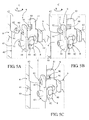
- a first one-piece frame 6 1 is positioned inside the safety perimeter P, and the lower end 42 of its post segment 40 is engaged on the upper end 41 of the post segment 40 of the one-piece frame 6 of the lower level 2 by shifting the approximately 1/8 of a turn to escape the locking devices 10 and is then rotated (arrow R in the Figures 5A and 5B ) Of about 1/8 of a turn about its pivot axis C to bring the locking fingers 91 into the slots 90 until the radial stop 92 abuts against the corresponding locking device 10 and stops the movement.
- the first one-piece frame 6 1 is pivoted ( figure 3A ) about its pivot axis C inside the safety perimeter P to be able to fit the through hole 81 of the first one-piece frame 6 1 on the pawl pin 80 of the fourth one-piece frame 6 4 in order to lock this horizontal assembly by the tilting of the pawl 82.
- These steps can be reproduced as many times as there are levels 2 to superimpose. To dismount such a shoring tower 1, these steps are carried out in the opposite direction, without it being possible to remove or disconnect a one-piece frame 6 from one of the levels 6 without having previously disassembled the upper levels 6.
- the figures 6 and 7 illustrate an alternative embodiment of the first locking means 8 to obtain an automatic horizontal locking, ie an automatic tilting of the pawl 820 in the locked position without intervention of the operator.
- This alternative embodiment is also the subject of the patent application. FR 13/50506 filed on January 21, 2013 by the plaintiff.
- the constituent parts identical to the previous example bear the same reference numbers.
- This embodiment differs from the previous example by the shape of its pawl 820 and its through hole 810 described below.
- the locking device 100 is reinforced relative to the device of 10 and consists of a U-shaped metal part, radially attached to the upper end 41 of the pole segment 40.
- the upper projecting end of the U-branch comprises the housing 90 of the second locking means 9, for receiving the locking pin 91 of a monobloc frame 6 belonging to the upper level.
- the other leg of the U comprises a notch 93 disposed at the housing 90 to release access to the locking pin 91.
- the leg of the U carrying the housing 90 is extended in the lower part by a radial stop 94, intended to cooperate with the locking tab 830 provided with the through hole 810 of the first locking means 8.
- the ratchet pin 800 is integral with the locking device 100 and extends in the axis A parallel to the upper horizontal beam 61. It carries a pawl 820 forming a latch, pivotally mounted about a pivot axis D between a substantially horizontal position which allows it to enter the through hole 810, and a substantially vertical position that allows it to fall back to the rear of this hole to lock the horizontal assembly.
- the ratchet 820 has a particular shape that allows it to automatically adopt the substantially vertical position due to its own mass. For this purpose, its pivot axis D is offset at the upper part relative to its center of gravity.
- the through hole 810 of axis B is formed in a Z-shaped locking lug 830 integral with the free end of the upper horizontal lug 61, delimiting two vertical, parallel and offset stops, namely an upper abutment 831. upstream of a lower abutment 832 in the direction of the arrow R illustrating the pivoting movement about the pivot axis C of a one-piece frame 6 to be assembled to another adjacent monobloc frame 6 of the same level.
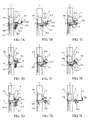
- this locking device 100 is explained in detail with reference to the Figures 7A to 7I when assembling and dismantling two adjacent monoblock frames 6 of the same level.
- the one-piece frames 6 are not shown to simplify the drawings. Only the column segment 40 of the already assembled frame, bearing the ratchet pin 800 integral with the locking device 100, and the Z-shaped locking lug 830 provided at the free end of the upper horizontal beam 61 of the frame are represented. to be assembled carrying the through hole 810.
- the Figure 7A shows the ratchet 820 in the substantially vertical position that it naturally occupies under the effect of its own mass. It comprises a head 821 located above its pivot axis D forming a front support zone and a rear stop, and a foot 822 located below its pivot axis D forming a ballast and provided with a cam profile. before.
- the head and the foot of the pawl 820 are interconnected by a curved central zone 823 forming a front clearance allowing entry of the pawl 820 into the through hole 810.
- the arrow M applied on the locking tab 830 represents the voluntary movement performed by the operator on the one-piece frame 6 to be assembled, namely the pivoting movement along the arrow R about the pivot axis C (see Figure 6A ).
- the Figure 7B shows that the voluntary action M performed by the operator causes the automatic pivoting of the pawl 820 around its pivot axis D in the direction of the arrow N towards its substantially horizontal position so that it enters the through hole 810, and this thanks to the lower stop 832 of the locking plate 830 which circulates on the front cam profile of the foot 822 of the pawl 820.
- the pawl 820 automatically pivots in the opposite direction along the arrow O to return to its substantially vertical initial position by gravity and lock the horizontal assembly of the two adjacent monoblock frames 6, without tools, no additional voluntary operation on the part of the operator.
- the Figure 7D illustrates this horizontal locking position, in which the locking tab 830, of the monobloc frame which has just been assembled, is locked in horizontal translation between the radial abutment 94 and the pawl 820 of the locking device 100 of the frame already assembled, respectively by its lower stops 832 and upper 831.
- the depth of the locking tab 830 is determined according to the the gap between the radial abutment 94 and the pawl 820 substantially vertical position. Thanks to this construction, the one-piece frames 6 are assembled and locked horizontally without play, guaranteeing optimal rigidity of the shoring tower 1.
- the pawl 820 will swing according to the arrow N ( figure 7E ) and position itself automatically against the locking tab 830 on two support points thus creating a double lock. So and as illustrated in the figure 7F , the locking tab 230 can not escape the pawl 820 without a voluntary intervention of the operator on said pawl.
- the U-shaped part of the locking device 100 which carries the ratchet pin 800, prevents any lifting of the locking tab 230, if the operator tries to escape the ratchet 820 by lifting said one-piece frame.
- the one-piece frames 6 used for the construction of the shoring tower 1 according to the invention or any other equivalent tower can be made by a welded assembly of tubular sections for example galvanized steel or the like, which has good strengths. both mechanical and climatic conditions.
- the locking means 8, 9 which are simplified and concentrated in common parts can be reported by welding on the relevant sections. Thus the design of these monobloc frames 6 provides competitive cost.
Landscapes
- Engineering & Computer Science (AREA)
- Architecture (AREA)
- Mechanical Engineering (AREA)
- Civil Engineering (AREA)
- Structural Engineering (AREA)
- Mutual Connection Of Rods And Tubes (AREA)
- Jib Cranes (AREA)
Claims (14)
- Modularer Stützturm (1) für Tief- und Hochbauarbeiten, bestehend aus Monoblock-Rahmen (6), die zusammengebaut werden, um übereinander aufstockbare Ebenen (2) zu bilden, wobei jede Ebene aus vier rechtwinklig zueinander montierte Monoblock-Rahmen (6) besteht und einen Sicherheitsbereich (P) bildet, wobei jeder Monoblock-Rahmen zumindest mit einem Ständer-Segment (40), einem oberen horizontalen Balken (61) und einem diagonalen Querverstrebungsbalken (63) versehen ist, wobei jeder Monoblock-Rahmen zudem erste Verriegelungs-Mittel (8) beträgt, die ausgelegt sind, um die aneinander liegenden Monoblock-Rahmen (6) jeder Ebene (2) paarweise zu verbinden, sowie zweite Verriegelungs-Mittel (9), die ausgelegt sind, um die Ständer-Segmente (40) der zwei übereinander liegenden Ebenen (2) entsprechenden Monoblock-Rahmen (6) paarweise zu verbinden, dadurch gekennzeichnet, dass die besagten ersten Verriegelungs-Mittel (8) jedes Monoblock-Rahmens (6) einerseits zumindest einen Klinkenzapfen (80, 800) mit Achse A betragen, der sich radial vom oberen Ende (41) des Ständer-Segments (40) parallel zum oberen horizontalen Balken (61) erstreckt, wobei besagte Klinke (82, 820) drehend auf besagtem Zapfen (80, 800) angeordnet ist und einen Riegel bildet, und andererseits eine Durchgangsöffnung (81, 810) mit Achse B und mit einer zu besagtem Klinkenzapfen (80, 800) komplementären Form, und die am freien Ende des besagten oberen horizontalen Balkens (61) angeordnet ist, dadurch, dass besagte Achsen A und B senkrecht zueinander sind und in einer selben horizontalen Ebene liegen, so dass besagter Klinkenzapfen (80, 800) und besagte Durchgangsöffnung (81, 810) von zwei anliegenden zusammen zu fügenden Monoblock-Rahmen (6) sich durch eine horizontale Drehbewegung (R) eines der Monoblock-Rahmen in Bezug auf den anderen um eine durch sein Ständer-Segment (40) definierte Drehachse (C) ineinander fügen, wobei besagte Drehbewegung (R) innerhalb des Sicherheitsbereichs (P) erfolgt und besagte Klinke (82, 820) ausgelegt ist, um besagten Klinkenzapfen (80, 800) hinter besagter Durchgangsöffnung (81, 810) in diesem Sicherheitsbereich (P) zu verriegeln.
- Stützturm nach Anspruch 1, dadurch gekennzeichnet, dass besagte Monoblock-Rahmen (6) jeder Ebene (2) identisch sind.
- Stützturm nach Anspruch 1, dadurch gekennzeichnet, dass besagte zweite Verriegelungs-Mittel (9) jedes Monoblock-Rahmens (6) zumindest eine Aufnahme (90) und einen Verriegelungs-Zapfen (91) mit komplementären Formen betragen, wovon die eine am oberen Ende (41) von Ständer-Segment (40) und der andere an einem unteren Ende (42) von besagtem Ständer-Segment (40) vorgesehen sind, wobei der Verriegelungs-Zapfen (91) eines Monoblock-Rahmens (6) einer Ebene (2) ausgelegt ist, um sich durch besagte horizontale Drehbewegung (R) vom betroffenen Monoblock-Rahmen um seine Drehachse (C) in der Aufnahme (90) eines Monoblock-Rahmens (6) einer anliegenden Ebene (2) zu verriegeln.
- Stützturm nach Anspruch 3, dadurch gekennzeichnet, dass der Klinkenzapfen (80, 800) der ersten Verriegelungsmittel (8) und die Aufnahme (90) der zweiten Verriegelungsmittel (9) am oberen Ende (41) des Ständer-Segments (40) jedes Monoblock-Rahmens (6) vorgesehen sind, dadurch, dass die Durchgangsöffnung (81, 810) der ersten Verriegelungsmittel (8) am freien Ende des oberen horizontalen Balkens (61) vorgesehen ist, und dadurch, dass der Verriegelungs-Zapfen (91) am unteren Ende (42) des Ständer-Segments (40) vorgesehen ist.
- Stützturm nach Anspruch 4, dadurch gekennzeichnet, dass der Klinkenzapfen (80, 800) der ersten Verriegelungsmittel (8) und die Aufnahme (90) der zweiten Verriegelungsmittel (9) Teil einer selben Verriegelungs-Vorrichtung (10, 100) sind, die radial am oberen Ende (41) des besagten Ständer-Segments (40) angebaut ist.
- Stützturm nach Anspruch 5, dadurch gekennzeichnet, dass das Ständer-Segment (40) jedes Monoblock-Rahmens (6) zumindest zwei identische Verriegelungs-Vorrichtungen (10, 100) beträgt, die radial an seinem oberen Ende (41) und um 90° versetzt angebaut sind, wobei sich eine der Verriegelungs-Vorrichtungen senkrecht zum oberen horizontalen Balken (61) erstreckt und sich die andere Verriegelungs-Vorrichtung gegenüber des besagten oberen horizontalen Balkens erstreckt.
- Stützturm nach einem beliebigen der Ansprüche 3 bis 6, dadurch gekennzeichnet, dass der Verriegelungs-Zapfen (91) der zweiten Verriegelungsmittel (9) einen Radial-Anschlag (92) aufweist, der ausgelegt ist, um die Amplitude der Drehbewegung (R) eines Monoblock-Rahmens (6) in Bezug auf einen anderen anliegenden Monoblock-Rahmen (6) zu begrenzen und sein Verlassen des besagten Sicherheitsbereichs (P) zu verhindern.
- Stützturm nach Anspruch 7, dadurch gekennzeichnet, dass die besagten zweiten Verriegelungsmittel (9) zumindest zwei radial am unteren Ende (42) von besagtem Ständer-Segment (40) hervorstehende, um einen Winkel von 90° versetzte Verriegelungs-Zapfen (91) betragen, wobei zumindest einer der besagten Verriegelungs-Zapfen besagten Radial-Anschlag (92) aufweist.
- Stützturm nach Anspruch 5, dadurch gekennzeichnet, dass besagte Verriegelungs-Vorrichtung (10, 100) zumindest eine senkrechte Platte (11) beträgt, die sich radial am oberen Ende (42) von Ständer-Segment (40) erstreckt und ausgelegt ist, um einen Träger für eine Fußleiste zu bilden, und dadurch, dass besagte senkrechte Platte zumindest die Aufnahme (90) der besagten zweiten Verriegelungsmittel (9) und den Klinkenzapfen (80, 800) der besagten ersten Verriegelungsmittel (8) beträgt.
- Stützturm nach Anspruch 1, dadurch gekennzeichnet, dass jeder Monoblock-Rahmen (6) zudem einen unteren horizontalen Balken (62) beträgt, der sich von besagtem Ständer-Segment (40) aus erstreckt und über zwei V-förmig angebrachte Querverstrebungsbalken (63, 64) mit der oberem horizontalen Balken (61) verbunden ist.
- Stützturm nach Anspruch 10, dadurch gekennzeichnet, dass jeder Monoblock-Rahmen (6) ein zentrales Leiter-Segment (70) beträgt, das sich vertikal zwischen dem oberen (61) und dem unteren (62) horizontalen Balken, in der von den beiden Querverstrebungsbalken (63, 64) gebildeten V-Form erstreckt.
- Stützturm nach Anspruch 1, dadurch gekennzeichnet, dass Klinke (820) auf besagten Zapfen (800) um eine in Bezug auf ihren Schwerpunkt versetzte Drehachse (D) montiert ist, so dass besagte Klinke (820) unter der Einwirkung ihrer eigenen Masse natürlicherweise eine merklich vertikale Position einnimmt.
- Stützturm nach Anspruch 12, dadurch gekennzeichnet, dass besagte Klinke (820) in ihrem Oberteil einen oberhalb ihrer Drehachse (D) befindlichen Kopf (821) beträgt, der einen vorderen Abstützungsbereich und einen hinteren Anschlag bildet sowie, in ihrem Unterteil, einen unterhalb von besagter Drehachse (D) befindlichen Fuß (822), der einen Ballast mit einem vorderen Nockenprofil bildet.
- Stützturm nach Anspruch 13, dadurch gekennzeichnet, dass Durchgangsöffnung (810) in einer Z-förmigen Verriegelungslasche (830) angeordnet ist, die einen oberen Anschlag (831) und einen unteren Anschlag (832) begrenzt, deren Abstand dem Abstand zwischen dem hinteren Anschlag des Kopfs (821) der Klinke (820) und einem unteren radialen Anschlag (94) der Verriegelungs-Vorrichtung (100) entspricht.
Applications Claiming Priority (2)
| Application Number | Priority Date | Filing Date | Title |
|---|---|---|---|
| FR1258504A FR2995333B1 (fr) | 2012-09-11 | 2012-09-11 | Tour d'etaiement modulaire notamment pour le genie civil |
| FR1350506A FR3001243B1 (fr) | 2013-01-21 | 2013-01-21 | Element de construction, notamment pour echafaudage ou similaire, pourvu d'un dispositif de verrouillage |
Publications (2)
| Publication Number | Publication Date |
|---|---|
| EP2706166A1 EP2706166A1 (de) | 2014-03-12 |
| EP2706166B1 true EP2706166B1 (de) | 2015-04-01 |
Family
ID=49231406
Family Applications (1)
| Application Number | Title | Priority Date | Filing Date |
|---|---|---|---|
| EP20130360027 Active EP2706166B1 (de) | 2012-09-11 | 2013-09-10 | Modularer Stützturm für Tief- und Hochbauarbeiten |
Country Status (3)
| Country | Link |
|---|---|
| EP (1) | EP2706166B1 (de) |
| ES (1) | ES2539930T3 (de) |
| PT (1) | PT2706166E (de) |
Families Citing this family (3)
| Publication number | Priority date | Publication date | Assignee | Title |
|---|---|---|---|---|
| NO2688526T3 (de) * | 2014-10-31 | 2018-03-10 | ||
| DE102020133810A1 (de) * | 2020-12-16 | 2022-06-23 | Peri Ag | Verbinder für ein Modulgerüst, Modulgerüst, Verfahren zur Herstellung eines Modulgerüsts sowie Verwendung eines Verbinders |
| PL444348A1 (pl) * | 2023-04-06 | 2024-10-07 | Altrad-Mostostal Spółka Z Ograniczoną Odpowiedzialnością | Wieża podporowa |
Family Cites Families (4)
| Publication number | Priority date | Publication date | Assignee | Title |
|---|---|---|---|---|
| FR2421253A1 (fr) * | 1978-03-30 | 1979-10-26 | Cambon Michel | Dispositif pour faire varier la hauteur des poteaux d'un echafaudage-tour |
| ES2203270B1 (es) * | 2001-02-14 | 2005-02-16 | Ingenieria De Encofrados Y Servicios, S.L. | Perfeccionamientos en andamios de fachada. |
| FR2879638B1 (fr) * | 2004-12-17 | 2007-03-30 | Mills Sa | Cadre pour tour d'etaiement et tour d'etaiement qui en est equipee |
| FR2939464B1 (fr) | 2008-12-10 | 2018-01-05 | Mills | Perfectionnement aux tours d'etaiement |
-
2013
- 2013-09-10 PT PT133600270T patent/PT2706166E/pt unknown
- 2013-09-10 EP EP20130360027 patent/EP2706166B1/de active Active
- 2013-09-10 ES ES13360027.0T patent/ES2539930T3/es active Active
Also Published As
| Publication number | Publication date |
|---|---|
| PT2706166E (pt) | 2015-08-05 |
| EP2706166A1 (de) | 2014-03-12 |
| ES2539930T3 (es) | 2015-07-07 |
Similar Documents
| Publication | Publication Date | Title |
|---|---|---|
| FR3058432B1 (fr) | Perfectionnement aux tours d'etaiement. | |
| EP3192941B1 (de) | Gerüst, das ein absenkbares geländer umfasst | |
| EP2044273B1 (de) | Stützmast | |
| EP4367344A1 (de) | Gerüstturm und gerüst sowie verwendung des turms und des gerüsts | |
| WO2017191391A1 (fr) | Module pour réaliser un escalier de chantier tournant, ensemble comportant au moins un tel module et escalier de chantier comportant au moins un tel ensemble | |
| FR2929304A1 (fr) | Dispositif d'echafaudage repliable et a hauteur de travail modulable | |
| EP2706166B1 (de) | Modularer Stützturm für Tief- und Hochbauarbeiten | |
| FR2975116A1 (fr) | Echafaudage pliant | |
| FR3045086A1 (fr) | Garde-corps rabattable pour toit terrasse, batiment modulaire comprenant au moins un garde-corps rabattable et construction modulaire comprenant au moins deux batiments modulaires | |
| EP0511921A1 (de) | Modularer Zusammenbau von Deckenschalungstützen; Verfahren und Schalung mit Anwendung dieses Zusammenbaus | |
| EP2216464B1 (de) | Modularer Belag | |
| FR3166650A1 (fr) | Tour d’échafaudage et échafaudage et utilisation de la tour et de l’échafaudage | |
| FR2995333A1 (fr) | Tour d'etaiement modulaire notamment pour le genie civil | |
| EP2177691B1 (de) | Gerüststruktur mit integrierter Treppe | |
| FR3124814A1 (fr) | Echafaudage et utilisation de l’échafaudage | |
| EP1067253B1 (de) | Gerüstrahmen und Gerüst damit zusammengesetzt | |
| FR3115309A1 (fr) | Dispositif de fixation d’un poteau | |
| EP2757210B1 (de) | Bauelement, insbesondere für Gerüst oder ähnliches, das mit einer Verriegelungsvorrichtung versehen ist | |
| EP1073814B1 (de) | Schutzgeländer | |
| CH658878A5 (en) | Prefabricated tubular scaffolding | |
| EP1700977B1 (de) | Verriegelungsvorrichtung für Rahmen von Gerüsten und Stütztürmen | |
| FR2944305A1 (fr) | Garde-corps pour echafaudage | |
| FR3138823A1 (fr) | Structure de travail temporaire | |
| FR3092847A1 (fr) | Escalier provisoire métallique | |
| FR2729418A1 (fr) | Echafaudage convertible multi-niveaux |
Legal Events
| Date | Code | Title | Description |
|---|---|---|---|
| PUAI | Public reference made under article 153(3) epc to a published international application that has entered the european phase |
Free format text: ORIGINAL CODE: 0009012 |
|
| AK | Designated contracting states |
Kind code of ref document: A1 Designated state(s): AL AT BE BG CH CY CZ DE DK EE ES FI FR GB GR HR HU IE IS IT LI LT LU LV MC MK MT NL NO PL PT RO RS SE SI SK SM TR |
|
| AX | Request for extension of the european patent |
Extension state: BA ME |
|
| 17P | Request for examination filed |
Effective date: 20140908 |
|
| RBV | Designated contracting states (corrected) |
Designated state(s): AL AT BE BG CH CY CZ DE DK EE ES FI FR GB GR HR HU IE IS IT LI LT LU LV MC MK MT NL NO PL PT RO RS SE SI SK SM TR |
|
| GRAP | Despatch of communication of intention to grant a patent |
Free format text: ORIGINAL CODE: EPIDOSNIGR1 |
|
| INTG | Intention to grant announced |
Effective date: 20141030 |
|
| GRAS | Grant fee paid |
Free format text: ORIGINAL CODE: EPIDOSNIGR3 |
|
| GRAA | (expected) grant |
Free format text: ORIGINAL CODE: 0009210 |
|
| AK | Designated contracting states |
Kind code of ref document: B1 Designated state(s): AL AT BE BG CH CY CZ DE DK EE ES FI FR GB GR HR HU IE IS IT LI LT LU LV MC MK MT NL NO PL PT RO RS SE SI SK SM TR |
|
| REG | Reference to a national code |
Ref country code: GB Ref legal event code: FG4D Free format text: NOT ENGLISH |
|
| REG | Reference to a national code |
Ref country code: CH Ref legal event code: EP |
|
| REG | Reference to a national code |
Ref country code: IE Ref legal event code: FG4D Free format text: LANGUAGE OF EP DOCUMENT: FRENCH |
|
| REG | Reference to a national code |
Ref country code: DE Ref legal event code: R096 Ref document number: 602013001376 Country of ref document: DE Effective date: 20150513 |
|
| REG | Reference to a national code |
Ref country code: AT Ref legal event code: REF Ref document number: 719189 Country of ref document: AT Kind code of ref document: T Effective date: 20150515 |
|
| REG | Reference to a national code |
Ref country code: ES Ref legal event code: FG2A Ref document number: 2539930 Country of ref document: ES Kind code of ref document: T3 Effective date: 20150707 |
|
| REG | Reference to a national code |
Ref country code: PT Ref legal event code: SC4A Free format text: AVAILABILITY OF NATIONAL TRANSLATION Effective date: 20150626 |
|
| REG | Reference to a national code |
Ref country code: NL Ref legal event code: VDEP Effective date: 20150401 |
|
| REG | Reference to a national code |
Ref country code: AT Ref legal event code: MK05 Ref document number: 719189 Country of ref document: AT Kind code of ref document: T Effective date: 20150401 |
|
| REG | Reference to a national code |
Ref country code: LT Ref legal event code: MG4D |
|
| PG25 | Lapsed in a contracting state [announced via postgrant information from national office to epo] |
Ref country code: NL Free format text: LAPSE BECAUSE OF FAILURE TO SUBMIT A TRANSLATION OF THE DESCRIPTION OR TO PAY THE FEE WITHIN THE PRESCRIBED TIME-LIMIT Effective date: 20150401 |
|
| REG | Reference to a national code |
Ref country code: FR Ref legal event code: PLFP Year of fee payment: 3 |
|
| PG25 | Lapsed in a contracting state [announced via postgrant information from national office to epo] |
Ref country code: NO Free format text: LAPSE BECAUSE OF FAILURE TO SUBMIT A TRANSLATION OF THE DESCRIPTION OR TO PAY THE FEE WITHIN THE PRESCRIBED TIME-LIMIT Effective date: 20150701 Ref country code: CZ Free format text: LAPSE BECAUSE OF FAILURE TO SUBMIT A TRANSLATION OF THE DESCRIPTION OR TO PAY THE FEE WITHIN THE PRESCRIBED TIME-LIMIT Effective date: 20150401 Ref country code: LT Free format text: LAPSE BECAUSE OF FAILURE TO SUBMIT A TRANSLATION OF THE DESCRIPTION OR TO PAY THE FEE WITHIN THE PRESCRIBED TIME-LIMIT Effective date: 20150401 Ref country code: FI Free format text: LAPSE BECAUSE OF FAILURE TO SUBMIT A TRANSLATION OF THE DESCRIPTION OR TO PAY THE FEE WITHIN THE PRESCRIBED TIME-LIMIT Effective date: 20150401 Ref country code: HR Free format text: LAPSE BECAUSE OF FAILURE TO SUBMIT A TRANSLATION OF THE DESCRIPTION OR TO PAY THE FEE WITHIN THE PRESCRIBED TIME-LIMIT Effective date: 20150401 |
|
| PG25 | Lapsed in a contracting state [announced via postgrant information from national office to epo] |
Ref country code: AT Free format text: LAPSE BECAUSE OF FAILURE TO SUBMIT A TRANSLATION OF THE DESCRIPTION OR TO PAY THE FEE WITHIN THE PRESCRIBED TIME-LIMIT Effective date: 20150401 Ref country code: GR Free format text: LAPSE BECAUSE OF FAILURE TO SUBMIT A TRANSLATION OF THE DESCRIPTION OR TO PAY THE FEE WITHIN THE PRESCRIBED TIME-LIMIT Effective date: 20150702 Ref country code: LV Free format text: LAPSE BECAUSE OF FAILURE TO SUBMIT A TRANSLATION OF THE DESCRIPTION OR TO PAY THE FEE WITHIN THE PRESCRIBED TIME-LIMIT Effective date: 20150401 Ref country code: IS Free format text: LAPSE BECAUSE OF FAILURE TO SUBMIT A TRANSLATION OF THE DESCRIPTION OR TO PAY THE FEE WITHIN THE PRESCRIBED TIME-LIMIT Effective date: 20150801 Ref country code: RS Free format text: LAPSE BECAUSE OF FAILURE TO SUBMIT A TRANSLATION OF THE DESCRIPTION OR TO PAY THE FEE WITHIN THE PRESCRIBED TIME-LIMIT Effective date: 20150401 |
|
| REG | Reference to a national code |
Ref country code: DE Ref legal event code: R097 Ref document number: 602013001376 Country of ref document: DE |
|
| PG25 | Lapsed in a contracting state [announced via postgrant information from national office to epo] |
Ref country code: DK Free format text: LAPSE BECAUSE OF FAILURE TO SUBMIT A TRANSLATION OF THE DESCRIPTION OR TO PAY THE FEE WITHIN THE PRESCRIBED TIME-LIMIT Effective date: 20150401 Ref country code: EE Free format text: LAPSE BECAUSE OF FAILURE TO SUBMIT A TRANSLATION OF THE DESCRIPTION OR TO PAY THE FEE WITHIN THE PRESCRIBED TIME-LIMIT Effective date: 20150401 |
|
| PLBE | No opposition filed within time limit |
Free format text: ORIGINAL CODE: 0009261 |
|
| STAA | Information on the status of an ep patent application or granted ep patent |
Free format text: STATUS: NO OPPOSITION FILED WITHIN TIME LIMIT |
|
| PG25 | Lapsed in a contracting state [announced via postgrant information from national office to epo] |
Ref country code: RO Free format text: LAPSE BECAUSE OF NON-PAYMENT OF DUE FEES Effective date: 20150401 Ref country code: SK Free format text: LAPSE BECAUSE OF FAILURE TO SUBMIT A TRANSLATION OF THE DESCRIPTION OR TO PAY THE FEE WITHIN THE PRESCRIBED TIME-LIMIT Effective date: 20150401 Ref country code: PL Free format text: LAPSE BECAUSE OF FAILURE TO SUBMIT A TRANSLATION OF THE DESCRIPTION OR TO PAY THE FEE WITHIN THE PRESCRIBED TIME-LIMIT Effective date: 20150401 |
|
| 26N | No opposition filed |
Effective date: 20160105 |
|
| PG25 | Lapsed in a contracting state [announced via postgrant information from national office to epo] |
Ref country code: MC Free format text: LAPSE BECAUSE OF FAILURE TO SUBMIT A TRANSLATION OF THE DESCRIPTION OR TO PAY THE FEE WITHIN THE PRESCRIBED TIME-LIMIT Effective date: 20150401 |
|
| PG25 | Lapsed in a contracting state [announced via postgrant information from national office to epo] |
Ref country code: SI Free format text: LAPSE BECAUSE OF FAILURE TO SUBMIT A TRANSLATION OF THE DESCRIPTION OR TO PAY THE FEE WITHIN THE PRESCRIBED TIME-LIMIT Effective date: 20150401 |
|
| REG | Reference to a national code |
Ref country code: IE Ref legal event code: MM4A |
|
| PG25 | Lapsed in a contracting state [announced via postgrant information from national office to epo] |
Ref country code: IE Free format text: LAPSE BECAUSE OF NON-PAYMENT OF DUE FEES Effective date: 20150910 |
|
| REG | Reference to a national code |
Ref country code: FR Ref legal event code: PLFP Year of fee payment: 4 |
|
| PG25 | Lapsed in a contracting state [announced via postgrant information from national office to epo] |
Ref country code: MT Free format text: LAPSE BECAUSE OF FAILURE TO SUBMIT A TRANSLATION OF THE DESCRIPTION OR TO PAY THE FEE WITHIN THE PRESCRIBED TIME-LIMIT Effective date: 20150401 |
|
| REG | Reference to a national code |
Ref country code: CH Ref legal event code: PL |
|
| PG25 | Lapsed in a contracting state [announced via postgrant information from national office to epo] |
Ref country code: BG Free format text: LAPSE BECAUSE OF FAILURE TO SUBMIT A TRANSLATION OF THE DESCRIPTION OR TO PAY THE FEE WITHIN THE PRESCRIBED TIME-LIMIT Effective date: 20150401 Ref country code: HU Free format text: LAPSE BECAUSE OF FAILURE TO SUBMIT A TRANSLATION OF THE DESCRIPTION OR TO PAY THE FEE WITHIN THE PRESCRIBED TIME-LIMIT; INVALID AB INITIO Effective date: 20130910 |
|
| PG25 | Lapsed in a contracting state [announced via postgrant information from national office to epo] |
Ref country code: CY Free format text: LAPSE BECAUSE OF FAILURE TO SUBMIT A TRANSLATION OF THE DESCRIPTION OR TO PAY THE FEE WITHIN THE PRESCRIBED TIME-LIMIT Effective date: 20150401 Ref country code: SE Free format text: LAPSE BECAUSE OF FAILURE TO SUBMIT A TRANSLATION OF THE DESCRIPTION OR TO PAY THE FEE WITHIN THE PRESCRIBED TIME-LIMIT Effective date: 20150401 |
|
| PG25 | Lapsed in a contracting state [announced via postgrant information from national office to epo] |
Ref country code: LI Free format text: LAPSE BECAUSE OF NON-PAYMENT OF DUE FEES Effective date: 20160930 Ref country code: CH Free format text: LAPSE BECAUSE OF NON-PAYMENT OF DUE FEES Effective date: 20160930 |
|
| REG | Reference to a national code |
Ref country code: FR Ref legal event code: PLFP Year of fee payment: 5 |
|
| PG25 | Lapsed in a contracting state [announced via postgrant information from national office to epo] |
Ref country code: SM Free format text: LAPSE BECAUSE OF FAILURE TO SUBMIT A TRANSLATION OF THE DESCRIPTION OR TO PAY THE FEE WITHIN THE PRESCRIBED TIME-LIMIT Effective date: 20150401 |
|
| PG25 | Lapsed in a contracting state [announced via postgrant information from national office to epo] |
Ref country code: TR Free format text: LAPSE BECAUSE OF FAILURE TO SUBMIT A TRANSLATION OF THE DESCRIPTION OR TO PAY THE FEE WITHIN THE PRESCRIBED TIME-LIMIT Effective date: 20150401 Ref country code: MK Free format text: LAPSE BECAUSE OF FAILURE TO SUBMIT A TRANSLATION OF THE DESCRIPTION OR TO PAY THE FEE WITHIN THE PRESCRIBED TIME-LIMIT Effective date: 20150401 |
|
| REG | Reference to a national code |
Ref country code: FR Ref legal event code: PLFP Year of fee payment: 6 |
|
| PG25 | Lapsed in a contracting state [announced via postgrant information from national office to epo] |
Ref country code: AL Free format text: LAPSE BECAUSE OF FAILURE TO SUBMIT A TRANSLATION OF THE DESCRIPTION OR TO PAY THE FEE WITHIN THE PRESCRIBED TIME-LIMIT Effective date: 20150401 |
|
| PGFP | Annual fee paid to national office [announced via postgrant information from national office to epo] |
Ref country code: LU Payment date: 20230822 Year of fee payment: 11 |
|
| PGFP | Annual fee paid to national office [announced via postgrant information from national office to epo] |
Ref country code: IT Payment date: 20230908 Year of fee payment: 11 Ref country code: GB Payment date: 20230920 Year of fee payment: 11 |
|
| PGFP | Annual fee paid to national office [announced via postgrant information from national office to epo] |
Ref country code: PT Payment date: 20230818 Year of fee payment: 11 Ref country code: DE Payment date: 20230911 Year of fee payment: 11 Ref country code: BE Payment date: 20230914 Year of fee payment: 11 |
|
| PGFP | Annual fee paid to national office [announced via postgrant information from national office to epo] |
Ref country code: ES Payment date: 20231006 Year of fee payment: 11 |
|
| REG | Reference to a national code |
Ref country code: DE Ref legal event code: R119 Ref document number: 602013001376 Country of ref document: DE |
|
| PG25 | Lapsed in a contracting state [announced via postgrant information from national office to epo] |
Ref country code: PT Free format text: LAPSE BECAUSE OF NON-PAYMENT OF DUE FEES Effective date: 20250310 |
|
| PG25 | Lapsed in a contracting state [announced via postgrant information from national office to epo] |
Ref country code: LU Free format text: LAPSE BECAUSE OF NON-PAYMENT OF DUE FEES Effective date: 20240910 |
|
| GBPC | Gb: european patent ceased through non-payment of renewal fee |
Effective date: 20240910 |
|
| PG25 | Lapsed in a contracting state [announced via postgrant information from national office to epo] |
Ref country code: DE Free format text: LAPSE BECAUSE OF NON-PAYMENT OF DUE FEES Effective date: 20250401 |
|
| PG25 | Lapsed in a contracting state [announced via postgrant information from national office to epo] |
Ref country code: GB Free format text: LAPSE BECAUSE OF NON-PAYMENT OF DUE FEES Effective date: 20240910 |
|
| REG | Reference to a national code |
Ref country code: BE Ref legal event code: MM Effective date: 20240930 |
|
| PG25 | Lapsed in a contracting state [announced via postgrant information from national office to epo] |
Ref country code: BE Free format text: LAPSE BECAUSE OF NON-PAYMENT OF DUE FEES Effective date: 20240930 Ref country code: IT Free format text: LAPSE BECAUSE OF NON-PAYMENT OF DUE FEES Effective date: 20240910 |
|
| PGFP | Annual fee paid to national office [announced via postgrant information from national office to epo] |
Ref country code: FR Payment date: 20250925 Year of fee payment: 13 |
|
| REG | Reference to a national code |
Ref country code: ES Ref legal event code: FD2A Effective date: 20251030 |
|
| PG25 | Lapsed in a contracting state [announced via postgrant information from national office to epo] |
Ref country code: ES Free format text: LAPSE BECAUSE OF NON-PAYMENT OF DUE FEES Effective date: 20240911 |