EP2706228B1 - Rotor blade assembly for a wind turbine - Google Patents
Rotor blade assembly for a wind turbine Download PDFInfo
- Publication number
- EP2706228B1 EP2706228B1 EP13183019.2A EP13183019A EP2706228B1 EP 2706228 B1 EP2706228 B1 EP 2706228B1 EP 13183019 A EP13183019 A EP 13183019A EP 2706228 B1 EP2706228 B1 EP 2706228B1
- Authority
- EP
- European Patent Office
- Prior art keywords
- rotor blade
- strip
- accessory
- blade assembly
- blade
- Prior art date
- Legal status (The legal status is an assumption and is not a legal conclusion. Google has not performed a legal analysis and makes no representation as to the accuracy of the status listed.)
- Active
Links
Images


Classifications
-
- F—MECHANICAL ENGINEERING; LIGHTING; HEATING; WEAPONS; BLASTING
- F03—MACHINES OR ENGINES FOR LIQUIDS; WIND, SPRING, OR WEIGHT MOTORS; PRODUCING MECHANICAL POWER OR A REACTIVE PROPULSIVE THRUST, NOT OTHERWISE PROVIDED FOR
- F03D—WIND MOTORS
- F03D1/00—Wind motors with rotation axis substantially parallel to the air flow entering the rotor
- F03D1/06—Rotors
- F03D1/065—Rotors characterised by their construction elements
- F03D1/0675—Rotors characterised by their construction elements of the blades
-
- F—MECHANICAL ENGINEERING; LIGHTING; HEATING; WEAPONS; BLASTING
- F05—INDEXING SCHEMES RELATING TO ENGINES OR PUMPS IN VARIOUS SUBCLASSES OF CLASSES F01-F04
- F05B—INDEXING SCHEME RELATING TO WIND, SPRING, WEIGHT, INERTIA OR LIKE MOTORS, TO MACHINES OR ENGINES FOR LIQUIDS COVERED BY SUBCLASSES F03B, F03D AND F03G
- F05B2240/00—Components
- F05B2240/20—Rotors
- F05B2240/30—Characteristics of rotor blades, i.e. of any element transforming dynamic fluid energy to or from rotational energy and being attached to a rotor
-
- F—MECHANICAL ENGINEERING; LIGHTING; HEATING; WEAPONS; BLASTING
- F05—INDEXING SCHEMES RELATING TO ENGINES OR PUMPS IN VARIOUS SUBCLASSES OF CLASSES F01-F04
- F05B—INDEXING SCHEME RELATING TO WIND, SPRING, WEIGHT, INERTIA OR LIKE MOTORS, TO MACHINES OR ENGINES FOR LIQUIDS COVERED BY SUBCLASSES F03B, F03D AND F03G
- F05B2260/00—Function
- F05B2260/30—Retaining components in desired mutual position
-
- F—MECHANICAL ENGINEERING; LIGHTING; HEATING; WEAPONS; BLASTING
- F05—INDEXING SCHEMES RELATING TO ENGINES OR PUMPS IN VARIOUS SUBCLASSES OF CLASSES F01-F04
- F05B—INDEXING SCHEME RELATING TO WIND, SPRING, WEIGHT, INERTIA OR LIKE MOTORS, TO MACHINES OR ENGINES FOR LIQUIDS COVERED BY SUBCLASSES F03B, F03D AND F03G
- F05B2260/00—Function
- F05B2260/96—Preventing, counteracting or reducing vibration or noise
-
- Y—GENERAL TAGGING OF NEW TECHNOLOGICAL DEVELOPMENTS; GENERAL TAGGING OF CROSS-SECTIONAL TECHNOLOGIES SPANNING OVER SEVERAL SECTIONS OF THE IPC; TECHNICAL SUBJECTS COVERED BY FORMER USPC CROSS-REFERENCE ART COLLECTIONS [XRACs] AND DIGESTS
- Y02—TECHNOLOGIES OR APPLICATIONS FOR MITIGATION OR ADAPTATION AGAINST CLIMATE CHANGE
- Y02E—REDUCTION OF GREENHOUSE GAS [GHG] EMISSIONS, RELATED TO ENERGY GENERATION, TRANSMISSION OR DISTRIBUTION
- Y02E10/00—Energy generation through renewable energy sources
- Y02E10/70—Wind energy
- Y02E10/72—Wind turbines with rotation axis in wind direction
Definitions
- the present disclosure relates in general to wind turbine rotor blades, and more particularly to a system for attaching an accessory component to a wind turbine rotor blade.
- Wind power is considered one of the cleanest, most environmentally friendly energy sources presently available, and wind turbines have gained increased attention in this regard.
- a modern wind turbine typically includes a tower, generator, gearbox, nacelle, and one or more rotor blades.
- the rotor blades capture kinetic energy of wind using known foil principles.
- the rotor blades transmit the kinetic energy in the form of rotational energy so as to turn a shaft coupling the rotor blades to a gearbox, or if a gearbox is not used, directly to the generator.
- the generator then converts the mechanical energy to electrical energy that may be deployed to a utility grid.
- various accessory components are attached to the rotor blades of wind turbines to perform various functions during operation of the wind turbine. Frequently, these components are attached adjacent to the trailing edges of the rotor blades.
- noise reducers or flow enhancers may be attached to the trailing edges of the rotor blades to reduce the noise and increase the aerodynamic efficiency of the rotor blade. See, for example, US 2011/268558 , US 2012/134817 and US 2012/141269 .
- Typical prior art noise reducers are often provided as serrated strips mounted directly to a trailing edge surface of the rotor blade using glue or another suitable adhesive.
- This configuration may have a variety of disadvantages.
- the noise reducers are generally mounted to rotor blades during manufacturing before the rotor blades are transported to the wind turbine site. The noise reducers are thus easily susceptible to damage during transportation. Attachment of the serrated strips to the stiffer blade material using a relatively high modulus adhesive or glue results in high shear stresses being imparted to the strips during normal operational bending or twisting of the rotor blades, which makes the strips prone to cracking and delamination.
- the adhesives used to mount the blade accessories make replacement of the accessories difficult, expensive, and time consuming.
- an improved attachment system for wind turbine rotor blade accessories such as serrated noise reducer strips, would be desired.
- an attachment system that allows for on-site mounting to a rotor blade would be advantageous.
- a system that reduces damage to the accessories from high shear stresses would be advantageous, as well as a system that allows for relatively easy, cost-effective, and efficient replacement.
- Fig. 1 illustrates a wind turbine 10 of conventional construction.
- the wind turbine 10 includes a tower 12 with a nacelle 14 mounted thereon.
- a plurality of rotor blades 16 are mounted to a rotor hub 18, which is in turn connected to a main flange that turns a main rotor shaft.
- the wind turbine power generation and control components are housed within the nacelle 14.
- the view of Fig. 1 is provided for illustrative purposes only to place the present invention in an exemplary field of use. It should be appreciated that the invention is not limited to any particular type of wind turbine configuration.
- a rotor blade 16 may include surfaces defining a pressure side 22 and a suction side 24 extending between a leading edge 26 and a trailing edge 28.
- the rotor blade 16 may extend from a blade tip 32 to a blade root 34.
- the surfaces defining the pressure side 22, suction side 24, leading edge 26, and trailing edge 28 further define a rotor blade interior.
- the rotor blade 16 may include a plurality of individual blade segments aligned in an end-to-end order from the blade tip 32 to the blade root 34.
- Each of the individual blade segments may be uniquely configured so that the plurality of blade segments define a complete rotor blade 16 having a designed aerodynamic profile, length, and other desired characteristics.
- each of the blade segments may have an aerodynamic profile that corresponds to the aerodynamic profile of adjacent blade segments.
- the aerodynamic profiles of the blade segments may form a continuous aerodynamic profile of the rotor blade 16.
- the rotor blade 16 may be formed as a singular, unitary blade having the designed aerodynamic profile, length, and other desired characteristics.
- the rotor blade 16 may, in exemplary embodiments, be curved. Curving of the rotor blade 16 may entail bending the rotor blade 16 in a generally flap-wise direction and/or in a generally edgewise direction.
- the flap-wise direction may generally be construed as the direction (or the opposite direction) in which the aerodynamic lift acts on the rotor blade 16.
- the edgewise direction is generally perpendicular to the flap-wise direction.
- Flap-wise curvature of the rotor blade 16 is also known as prebend, while edgewise curvature is also known as sweep.
- a curved rotor blade 16 may be pre-bent and/or swept. Curving may enable the rotor blade 16 to better withstand flap-wise and edgewise loads during operation of the wind turbine 10, and may further provide clearance for the rotor blade 16 from the tower 12 during operation of the wind turbine 10.
- the rotor blade 16 may further define a pitch axis 40 ( Figs. 2 and 3 ) relative to the rotor hub 18 of the wind turbine 10.
- the pitch axis 40 may extend generally perpendicularly to the rotor hub 18 and blade root 34 through the center of the blade root 34.
- a pitch angle or blade pitch of the rotor blade 16, i.e., an angle that determines a perspective of the rotor blade 16 with respect to the air flow past the wind turbine 10, may be defined by rotation of the rotor blade 16 about the pitch axis 40.
- the rotor blade 16 may further define chord 42 and a span 44. As shown in Figs. 2 and 3 , the chord 42 may vary throughout the span 44 of the rotor blade 16. Thus, as discussed below, a local chord 46 may be defined for the rotor blade 16 at any point on the rotor blade 16 along the span 44.
- the present disclosure relates to a rotor blade assembly 100 that includes a strip-member blade accessory 110 configured on the rotor blade 16.
- the blade accessory 110 is an elongated member that is attached to one of the blade surfaces for any intended functionality.
- known structures are attached to wind turbine rotor blades 16 to enhance the aerodynamic efficiency/performance of the blades.
- Other known structures are attached to reduce the noise generated by the blade 16. It should be appreciated that the present invention is not limited to any particular type or configuration of blade accessory 110.
- the strip-member blade accessory 110 is a noise reducer 116 attached to the pressure side 22 or suction side 24 of the blade 16 along a portion of the trailing edge 28.
- the noise reducer 110 may be configured on a surface of the rotor blade 16 adjacent the leading edge 26 of the rotor blade 16, or adjacent the tip 32 or the root 34 of the rotor blade 16, or at any other suitable position on the rotor blade 16.
- Such devices are generally used to reduce the aerodynamic noise being emitted from the rotor blade 16 during operation of the wind turbine 10 and/or may increase the aerodynamic efficiency/performance of the rotor blade 16.
- the blade accessory 110 may be formed from various materials.
- a conventional construction is a relatively stiff fiberglass laminate material that is "stiffer" than the underlying shell material of the pressure 22 or suction 24 sides. As explained above, with conventional attachment means, stretching or flexing of the blade surfaces during normal operating conditions of the wind turbine 10 may impart significant sheer stresses to the blade accessory 110, resulting in any combination of cracking, debonding, or delamination of the blade accessory.
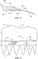
- the blade accessory 110 includes a base portion 114 attached to the blade surface.
- This base portion may be defined as a generally continuous plate-like structure that presents a generally flat, planar surface that contours and adheres to the mating blade surface.
- Functional components may be formed integral with the base portion 114, or separately attached t the base portion.
- a plurality of serrations 112 extend from the base portion 114. While in exemplary embodiments the serrations 112 are generally V-shaped, in alternative embodiments the serrations 112 may be U-shaped, or may have any other shape or configuration suitable for reducing the noise being emitted from and/or increasing the aerodynamic efficiency/performance of the rotor blade 16 during operation of the wind turbine 10. For example, in some non-limiting embodiments, the serrations 112 may be generally sinusoidal or squared-sinusoidal.
- an attachment layer 118 is provided to connect the base portion 114 of the blade accessory 110 to the rotor blade surface.
- This attachment layer 118 has a lower shear modulus than the base portion 114 to allow for shear slippage between the relatively stiff base portion 114 and the underlying rotor blade surface.
- the shear modulus is, in certain embodiments, within the range of 50Kpa - 1MPa.
- the attachment layer 118 may be a double-sided adhesive sheet or strip material 120, such as a Very High Bond (VHB)/SAFT (Solar Acrylic Foam Tape) foam-based tape.
- VHB/SAFT foam-based materials are commercially available, for example from 3M Corporation of St. Paul, Minnesota, USA.
- the foam attachment layer 120 will sheer a small but defined amount with flexing of the underlying blade surfaces, thus reducing sheer stresses in the blade accessory 110.
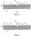
- the attachment layer 118 may be selected to have a particular thickness 122 ( Fig. 6 ) that provides the desired sheer slippage or strain isolation characteristic without adding a detrimental height aspect that could adversely affect the aerodynamic performance of the blade.
- the adhesive tape may have a thickness between 0.5 mm - 5.0 mm.
- the attachment layer 118 may be applied as a continuous strip between the base portion 114 and underlying blade surface, as depicted in Fig. 5 , or may be applied in a discontinuous pattern. According to the invention as depicted in Fig. 9 , the attachment layer 118 includes a plurality of distinct strips 120 (e.g., tape or sheet strips) with a chord-wise gap between adjacent strips. Also according to the invention, the attachment layer may include span-wise gaps between distinct strips 120.
- distinct strips 120 e.g., tape or sheet strips
- the length of the strip-member blade accessory 110 in combination with the attachment layer 118 is a factor that can be varied to reduce sheer stresses in the blade accessory 110. For example, fatigue testing has shown that, for the same type of attachment layer 118, at a certain length the blade accessory 110 will de-bond from the blade surface.
- the strip member blade accessory 110 has a length 124 ( Fig. 2 ) of between 0.1 meters to less than 2.0 meters. In a certain embodiment, the blade accessory 110 has a length of less than 1.0 meters.
- a blade assembly 100 wherein the blade accessory 110 is defined by a plurality of strip components 126 longitudinally aligned and attached along an edge of the blade 16 with a gap 128 ( Fig. 6 ) between adjacent components 126.
- the shorter components 126 have the reduced sheer stress advantages and combine to provide an effective noise reducer 112 along a substantial portion of the trailing edge 28.
- Each of the components 126 may have a length of between 0.1 meters to less than 2.0 meters.
- the attachment layer 118 e.g., tape 120
- the attachment layer 118 is discontinuous along the length of the components 126 and does not bridge the respective gaps 128.
- gaps 128 allow for relative sheer slippage between the different components 126 with less slippage and sheer strain on the individual tape sections.
- the gap 128 may be, for example, 5 mm.
- fillet seals 130 may be provided at the edges of the respective segments 126 to protect the attachment layer 118 from moisture or other elements.
- the seals 130 may be, for example, any type of flexible caulking material.
- Fig. 7 depicts an embodiment wherein the attachment layer 118 includes a layer of resin or putty 119 between the strip/sheet material layer 120 (such as a foam-based layer as described above) and the underlying blade composite material.
- the overall thickness 122 of the attachment layer 118 is preferably within the limits discussed above in this embodiment.
- Fig. 8 depicts an embodiment wherein the attachment layer 118 includes a layer of resin or putty 119 between the strip/sheet material layer 120 (such as a foam-based layer as described above) and the overlying blade accessory base portion 114.
Landscapes
- Engineering & Computer Science (AREA)
- Life Sciences & Earth Sciences (AREA)
- Sustainable Development (AREA)
- Sustainable Energy (AREA)
- Chemical & Material Sciences (AREA)
- Combustion & Propulsion (AREA)
- Mechanical Engineering (AREA)
- General Engineering & Computer Science (AREA)
- Wind Motors (AREA)
- Turbine Rotor Nozzle Sealing (AREA)
Applications Claiming Priority (1)
| Application Number | Priority Date | Filing Date | Title |
|---|---|---|---|
| US13/609,719 US9458821B2 (en) | 2012-09-11 | 2012-09-11 | Attachment system for a wind turbine rotor blade accessory |
Publications (3)
| Publication Number | Publication Date |
|---|---|
| EP2706228A2 EP2706228A2 (en) | 2014-03-12 |
| EP2706228A3 EP2706228A3 (en) | 2018-04-18 |
| EP2706228B1 true EP2706228B1 (en) | 2021-03-17 |
Family
ID=49115404
Family Applications (1)
| Application Number | Title | Priority Date | Filing Date |
|---|---|---|---|
| EP13183019.2A Active EP2706228B1 (en) | 2012-09-11 | 2013-09-04 | Rotor blade assembly for a wind turbine |
Country Status (6)
| Country | Link |
|---|---|
| US (1) | US9458821B2 (da) |
| EP (1) | EP2706228B1 (da) |
| AU (1) | AU2013222047B2 (da) |
| CA (1) | CA2826409C (da) |
| DK (1) | DK2706228T3 (da) |
| ES (1) | ES2874815T3 (da) |
Families Citing this family (35)
| Publication number | Priority date | Publication date | Assignee | Title |
|---|---|---|---|---|
| US9458821B2 (en) * | 2012-09-11 | 2016-10-04 | General Electric Company | Attachment system for a wind turbine rotor blade accessory |
| US9562513B2 (en) * | 2013-05-03 | 2017-02-07 | General Electric Company | Wind turbine rotor blade assembly with surface features |
| DK2896961T3 (da) * | 2014-01-20 | 2021-02-01 | Siemens Gamesa Renewable Energy As | Delamineringsindikator |
| DK2908001T3 (da) * | 2014-02-12 | 2017-01-02 | Siemens Ag | Midler til dæmpning af belastning på en vindmøllerotorvinge |
| DE102014206345A1 (de) * | 2014-04-02 | 2015-10-08 | Wobben Properties Gmbh | Verfahren zum Anbringen einer Zackenhinterkante an einer Blatthinterkante eines Rotorblattes |
| DE102014213929A1 (de) | 2014-07-17 | 2016-01-21 | Wobben Properties Gmbh | Rotorblatthinterkante |
| US11274651B2 (en) | 2014-08-05 | 2022-03-15 | Lm Wp Patent Holding A/S | Wind turbine blade provided with surface mounted device |
| US10100805B2 (en) * | 2015-10-12 | 2018-10-16 | General Electric Compant | Tip extension assembly for a wind turbine rotor blade |
| US10240576B2 (en) | 2015-11-25 | 2019-03-26 | General Electric Company | Wind turbine noise reduction with acoustically absorbent serrations |
| EP3181895A1 (en) * | 2015-12-17 | 2017-06-21 | LM WP Patent Holding A/S | Splitter plate arrangement for a serrated wind turbine blade |
| DK3431754T3 (da) * | 2016-02-12 | 2020-10-26 | Lm Wp Patent Holding As | Savtakket bagkantspanel til en vindmøllevinge |
| US10487796B2 (en) | 2016-10-13 | 2019-11-26 | General Electric Company | Attachment methods for surface features of wind turbine rotor blades |
| US10443579B2 (en) | 2016-11-15 | 2019-10-15 | General Electric Company | Tip extensions for wind turbine rotor blades and methods of installing same |
| ES2973128T3 (es) * | 2017-01-12 | 2024-06-18 | Lm Wind Power As | Una pala de turbina eólica que comprende un dispositivo de reducción de ruido en el borde de salida |
| US10830206B2 (en) | 2017-02-03 | 2020-11-10 | General Electric Company | Methods for manufacturing wind turbine rotor blades and components thereof |
| US11098691B2 (en) | 2017-02-03 | 2021-08-24 | General Electric Company | Methods for manufacturing wind turbine rotor blades and components thereof |
| US10711629B2 (en) | 2017-09-20 | 2020-07-14 | Generl Electric Company | Method of clearance control for an interdigitated turbine engine |
| US10458267B2 (en) | 2017-09-20 | 2019-10-29 | General Electric Company | Seal assembly for counter rotating turbine assembly |
| US11668275B2 (en) | 2017-11-21 | 2023-06-06 | General Electric Company | Methods for manufacturing an outer skin of a rotor blade |
| US10865769B2 (en) | 2017-11-21 | 2020-12-15 | General Electric Company | Methods for manufacturing wind turbine rotor blade panels having printed grid structures |
| US10773464B2 (en) | 2017-11-21 | 2020-09-15 | General Electric Company | Method for manufacturing composite airfoils |
| US11248582B2 (en) | 2017-11-21 | 2022-02-15 | General Electric Company | Multiple material combinations for printed reinforcement structures of rotor blades |
| US10913216B2 (en) | 2017-11-21 | 2021-02-09 | General Electric Company | Methods for manufacturing wind turbine rotor blade panels having printed grid structures |
| US11040503B2 (en) | 2017-11-21 | 2021-06-22 | General Electric Company | Apparatus for manufacturing composite airfoils |
| US11390013B2 (en) | 2017-11-21 | 2022-07-19 | General Electric Company | Vacuum forming mold assembly and associated methods |
| US10920745B2 (en) | 2017-11-21 | 2021-02-16 | General Electric Company | Wind turbine rotor blade components and methods of manufacturing the same |
| US10821652B2 (en) | 2017-11-21 | 2020-11-03 | General Electric Company | Vacuum forming mold assembly and method for creating a vacuum forming mold assembly |
| US11035339B2 (en) | 2018-03-26 | 2021-06-15 | General Electric Company | Shear web assembly interconnected with additive manufactured components |
| US10821696B2 (en) | 2018-03-26 | 2020-11-03 | General Electric Company | Methods for manufacturing flatback airfoils for wind turbine rotor blades |
| US10746157B2 (en) * | 2018-08-31 | 2020-08-18 | General Electric Company | Noise reducer for a wind turbine rotor blade having a cambered serration |
| EP3865703B1 (en) * | 2020-02-12 | 2025-06-11 | Siemens Gamesa Renewable Energy A/S | Wind turbine rotor blade leading-edge protector |
| US11428160B2 (en) | 2020-12-31 | 2022-08-30 | General Electric Company | Gas turbine engine with interdigitated turbine and gear assembly |
| CN117345517B (zh) * | 2022-06-27 | 2025-05-16 | 江苏金风科技有限公司 | 尾缘附件、尾缘附件的制造方法、风机叶片和风力发电机组 |
| EP4534276A1 (de) * | 2023-10-05 | 2025-04-09 | Wobben Properties GmbH | Windenergieanlagen-rotorblatt-hinterkantenkamm und verfahren zum herstellen eines windenergieanlagen-rotorblattes |
| USD1117049S1 (en) * | 2024-06-23 | 2026-03-10 | Naviga Wind Power Spólka Z Ograniczona Odpowiedzialnoscia | Rotor blade |
Citations (1)
| Publication number | Priority date | Publication date | Assignee | Title |
|---|---|---|---|---|
| EP2444658A1 (en) * | 2010-10-21 | 2012-04-25 | Siemens Aktiengesellschaft | Blade of a wind turbine |
Family Cites Families (32)
| Publication number | Priority date | Publication date | Assignee | Title |
|---|---|---|---|---|
| USRE19412E (en) | 1935-01-01 | Aircraft and control thereof | ||
| US2450440A (en) | 1944-12-19 | 1948-10-05 | Roscoe H Mills | Propeller blade construction |
| US3528753A (en) | 1968-06-14 | 1970-09-15 | United Aircraft Corp | Helicopter blade with non-homogeneous structural spar |
| US3586460A (en) | 1969-05-14 | 1971-06-22 | Us Air Force | Rotor blade variable modulus trailing edge |
| US4329119A (en) | 1977-08-02 | 1982-05-11 | The Boeing Company | Rotor blade internal damper |
| FR2542695B1 (fr) | 1983-03-18 | 1985-07-26 | Aerospatiale | Helice multipale a pas variable a pale s en materiaux composites demontables individuellement, procede de fabrication de telles pales et pales ainsi realisees |
| US5346367A (en) | 1984-12-21 | 1994-09-13 | United Technologies Corporation | Advanced composite rotor blade |
| US5088665A (en) | 1989-10-31 | 1992-02-18 | The United States Of America As Represented By The Administrator Of The National Aeronautics And Space Administration | Serrated trailing edges for improving lift and drag characteristics of lifting surfaces |
| US7059833B2 (en) | 2001-11-26 | 2006-06-13 | Bonus Energy A/S | Method for improvement of the efficiency of a wind turbine rotor |
| US7637721B2 (en) | 2005-07-29 | 2009-12-29 | General Electric Company | Methods and apparatus for producing wind energy with reduced wind turbine noise |
| ES2318925B1 (es) | 2005-09-22 | 2010-02-11 | GAMESA INNOVATION & TECHNOLOGY, S.L. | Aerogenerador con un rotor de palas que reduce el ruido. |
| US7458777B2 (en) | 2005-09-22 | 2008-12-02 | General Electric Company | Wind turbine rotor assembly and blade having acoustic flap |
| MX2008015664A (es) * | 2006-06-09 | 2009-03-25 | Vestas Wind Sys As | Aspa de turbina eolica y turbina eolica con regulacion por cambio en el angulo de paso. |
| ES2310958B1 (es) * | 2006-09-15 | 2009-11-10 | GAMESA INNOVATION & TECHNOLOGY, S.L. | Pala de aerogenerador optimizada. |
| US20090074585A1 (en) | 2007-09-19 | 2009-03-19 | General Electric Company | Wind turbine blades with trailing edge serrations |
| US8075278B2 (en) | 2009-05-21 | 2011-12-13 | Zuteck Michael D | Shell structure of wind turbine blade having regions of low shear modulus |
| US8079819B2 (en) | 2009-05-21 | 2011-12-20 | Zuteck Michael D | Optimization of premium fiber material usage in wind turbine spars |
| US8083488B2 (en) | 2010-08-23 | 2011-12-27 | General Electric Company | Blade extension for rotor blade in wind turbine |
| US8038407B2 (en) | 2010-09-14 | 2011-10-18 | General Electric Company | Wind turbine blade with improved trailing edge bond |
| US8523515B2 (en) * | 2010-11-15 | 2013-09-03 | General Electric Company | Noise reducer for rotor blade in wind turbine |
| US8047799B2 (en) * | 2010-12-13 | 2011-11-01 | General Electric Company | Wind turbine blades with improved bond line and associated method |
| US20110268558A1 (en) | 2010-12-20 | 2011-11-03 | General Electric Company | Noise reducer for rotor blade in wind turbine |
| ES2482615T3 (es) * | 2011-02-04 | 2014-08-04 | Lm Wp Patent Holding A/S | Dispositivo generador de torbellinos con secciones ahusadas para una turbina eólica |
| ES2451568T3 (es) * | 2011-02-04 | 2014-03-27 | Lm Wind Power A/S | Generador de torbellinos para turbina eólica con una base que tiene un rebaje para adhesivo |
| US8414261B2 (en) | 2011-05-31 | 2013-04-09 | General Electric Company | Noise reducer for rotor blade in wind turbine |
| US8834127B2 (en) * | 2011-09-09 | 2014-09-16 | General Electric Company | Extension for rotor blade in wind turbine |
| US8506250B2 (en) * | 2011-10-19 | 2013-08-13 | General Electric Company | Wind turbine rotor blade with trailing edge extension and method of attachment |
| DE102012000431A1 (de) * | 2012-01-12 | 2013-07-18 | Smart Blade Gmbh | Rotorblatt |
| ES2554908T3 (es) * | 2012-02-24 | 2015-12-28 | Siemens Aktiengesellschaft | Disposición para reducir el ruido originado por una pala de turbina eólica |
| DK177533B1 (en) * | 2012-05-25 | 2013-09-08 | Envision Energy Denmark Aps | Trailing edge tape |
| US9458821B2 (en) * | 2012-09-11 | 2016-10-04 | General Electric Company | Attachment system for a wind turbine rotor blade accessory |
| US9556849B2 (en) * | 2013-05-02 | 2017-01-31 | General Electric Company | Attachment system and method for wind turbine vortex generators |
-
2012
- 2012-09-11 US US13/609,719 patent/US9458821B2/en active Active
-
2013
- 2013-09-03 AU AU2013222047A patent/AU2013222047B2/en active Active
- 2013-09-04 ES ES13183019T patent/ES2874815T3/es active Active
- 2013-09-04 EP EP13183019.2A patent/EP2706228B1/en active Active
- 2013-09-04 DK DK13183019.2T patent/DK2706228T3/da active
- 2013-09-05 CA CA2826409A patent/CA2826409C/en active Active
Patent Citations (1)
| Publication number | Priority date | Publication date | Assignee | Title |
|---|---|---|---|---|
| EP2444658A1 (en) * | 2010-10-21 | 2012-04-25 | Siemens Aktiengesellschaft | Blade of a wind turbine |
Also Published As
| Publication number | Publication date |
|---|---|
| AU2013222047A1 (en) | 2014-03-27 |
| US20140072440A1 (en) | 2014-03-13 |
| AU2013222047B2 (en) | 2017-02-16 |
| US9458821B2 (en) | 2016-10-04 |
| DK2706228T3 (da) | 2021-06-21 |
| ES2874815T3 (es) | 2021-11-05 |
| CA2826409C (en) | 2017-03-07 |
| EP2706228A3 (en) | 2018-04-18 |
| CA2826409A1 (en) | 2014-03-11 |
| EP2706228A2 (en) | 2014-03-12 |
Similar Documents
| Publication | Publication Date | Title |
|---|---|---|
| EP2706228B1 (en) | Rotor blade assembly for a wind turbine | |
| EP2799709B1 (en) | Method for attachment of wind turbine vortex generators | |
| DK178210B1 (en) | Extension for rotor blade in wind turbine | |
| US10584676B2 (en) | Wind turbine rotor blade assembly with surface features | |
| DK178482B1 (en) | Noise reducer for rotor blade in wind turbine | |
| EP3091225B1 (en) | Wind turbine blade and attachment method to install components, such as tip extensions and winglets, to a wind turbine blade | |
| US8523515B2 (en) | Noise reducer for rotor blade in wind turbine | |
| DK178192B1 (da) | Støjreduktionsindretning til rotorvinge i en vindmølle | |
| AU2013231165B2 (en) | Noise reduction tab and method for wind turbine rotor blade | |
| CN105556115B (zh) | 具有波浪形后缘的风力涡轮机叶片 | |
| CA2869803C (en) | Noise reducing extension plate for rotor blade in wind turbine |
Legal Events
| Date | Code | Title | Description |
|---|---|---|---|
| PUAI | Public reference made under article 153(3) epc to a published international application that has entered the european phase |
Free format text: ORIGINAL CODE: 0009012 |
|
| AK | Designated contracting states |
Kind code of ref document: A2 Designated state(s): AL AT BE BG CH CY CZ DE DK EE ES FI FR GB GR HR HU IE IS IT LI LT LU LV MC MK MT NL NO PL PT RO RS SE SI SK SM TR |
|
| AX | Request for extension of the european patent |
Extension state: BA ME |
|
| PUAL | Search report despatched |
Free format text: ORIGINAL CODE: 0009013 |
|
| AK | Designated contracting states |
Kind code of ref document: A3 Designated state(s): AL AT BE BG CH CY CZ DE DK EE ES FI FR GB GR HR HU IE IS IT LI LT LU LV MC MK MT NL NO PL PT RO RS SE SI SK SM TR |
|
| AX | Request for extension of the european patent |
Extension state: BA ME |
|
| RIC1 | Information provided on ipc code assigned before grant |
Ipc: F03D 1/06 20060101AFI20180314BHEP |
|
| STAA | Information on the status of an ep patent application or granted ep patent |
Free format text: STATUS: REQUEST FOR EXAMINATION WAS MADE |
|
| 17P | Request for examination filed |
Effective date: 20181018 |
|
| RBV | Designated contracting states (corrected) |
Designated state(s): AL AT BE BG CH CY CZ DE DK EE ES FI FR GB GR HR HU IE IS IT LI LT LU LV MC MK MT NL NO PL PT RO RS SE SI SK SM TR |
|
| STAA | Information on the status of an ep patent application or granted ep patent |
Free format text: STATUS: EXAMINATION IS IN PROGRESS |
|
| 17Q | First examination report despatched |
Effective date: 20191023 |
|
| GRAP | Despatch of communication of intention to grant a patent |
Free format text: ORIGINAL CODE: EPIDOSNIGR1 |
|
| STAA | Information on the status of an ep patent application or granted ep patent |
Free format text: STATUS: GRANT OF PATENT IS INTENDED |
|
| INTG | Intention to grant announced |
Effective date: 20201111 |
|
| RIN1 | Information on inventor provided before grant (corrected) |
Inventor name: ZHU, QI Inventor name: JACOBSEN, ERIC MORGAN Inventor name: NAGABHUSHANA, PRADEEPA Inventor name: BAKHUIS, JAN WILLEM Inventor name: RIDDELL, SCOTT GABELL Inventor name: BUSBEY, BRUCE CLARK Inventor name: ESSER, JUERGEN |
|
| GRAS | Grant fee paid |
Free format text: ORIGINAL CODE: EPIDOSNIGR3 |
|
| GRAA | (expected) grant |
Free format text: ORIGINAL CODE: 0009210 |
|
| STAA | Information on the status of an ep patent application or granted ep patent |
Free format text: STATUS: THE PATENT HAS BEEN GRANTED |
|
| AK | Designated contracting states |
Kind code of ref document: B1 Designated state(s): AL AT BE BG CH CY CZ DE DK EE ES FI FR GB GR HR HU IE IS IT LI LT LU LV MC MK MT NL NO PL PT RO RS SE SI SK SM TR |
|
| REG | Reference to a national code |
Ref country code: GB Ref legal event code: FG4D |
|
| REG | Reference to a national code |
Ref country code: CH Ref legal event code: EP |
|
| REG | Reference to a national code |
Ref country code: DE Ref legal event code: R096 Ref document number: 602013076273 Country of ref document: DE |
|
| REG | Reference to a national code |
Ref country code: IE Ref legal event code: FG4D |
|
| REG | Reference to a national code |
Ref country code: AT Ref legal event code: REF Ref document number: 1372471 Country of ref document: AT Kind code of ref document: T Effective date: 20210415 |
|
| REG | Reference to a national code |
Ref country code: DK Ref legal event code: T3 Effective date: 20210616 |
|
| REG | Reference to a national code |
Ref country code: LT Ref legal event code: MG9D |
|
| PG25 | Lapsed in a contracting state [announced via postgrant information from national office to epo] |
Ref country code: NO Free format text: LAPSE BECAUSE OF FAILURE TO SUBMIT A TRANSLATION OF THE DESCRIPTION OR TO PAY THE FEE WITHIN THE PRESCRIBED TIME-LIMIT Effective date: 20210617 Ref country code: BG Free format text: LAPSE BECAUSE OF FAILURE TO SUBMIT A TRANSLATION OF THE DESCRIPTION OR TO PAY THE FEE WITHIN THE PRESCRIBED TIME-LIMIT Effective date: 20210617 Ref country code: HR Free format text: LAPSE BECAUSE OF FAILURE TO SUBMIT A TRANSLATION OF THE DESCRIPTION OR TO PAY THE FEE WITHIN THE PRESCRIBED TIME-LIMIT Effective date: 20210317 Ref country code: FI Free format text: LAPSE BECAUSE OF FAILURE TO SUBMIT A TRANSLATION OF THE DESCRIPTION OR TO PAY THE FEE WITHIN THE PRESCRIBED TIME-LIMIT Effective date: 20210317 Ref country code: GR Free format text: LAPSE BECAUSE OF FAILURE TO SUBMIT A TRANSLATION OF THE DESCRIPTION OR TO PAY THE FEE WITHIN THE PRESCRIBED TIME-LIMIT Effective date: 20210618 |
|
| REG | Reference to a national code |
Ref country code: AT Ref legal event code: MK05 Ref document number: 1372471 Country of ref document: AT Kind code of ref document: T Effective date: 20210317 |
|
| REG | Reference to a national code |
Ref country code: NL Ref legal event code: MP Effective date: 20210317 |
|
| PG25 | Lapsed in a contracting state [announced via postgrant information from national office to epo] |
Ref country code: RS Free format text: LAPSE BECAUSE OF FAILURE TO SUBMIT A TRANSLATION OF THE DESCRIPTION OR TO PAY THE FEE WITHIN THE PRESCRIBED TIME-LIMIT Effective date: 20210317 Ref country code: LV Free format text: LAPSE BECAUSE OF FAILURE TO SUBMIT A TRANSLATION OF THE DESCRIPTION OR TO PAY THE FEE WITHIN THE PRESCRIBED TIME-LIMIT Effective date: 20210317 Ref country code: SE Free format text: LAPSE BECAUSE OF FAILURE TO SUBMIT A TRANSLATION OF THE DESCRIPTION OR TO PAY THE FEE WITHIN THE PRESCRIBED TIME-LIMIT Effective date: 20210317 |
|
| PG25 | Lapsed in a contracting state [announced via postgrant information from national office to epo] |
Ref country code: NL Free format text: LAPSE BECAUSE OF FAILURE TO SUBMIT A TRANSLATION OF THE DESCRIPTION OR TO PAY THE FEE WITHIN THE PRESCRIBED TIME-LIMIT Effective date: 20210317 |
|
| PG25 | Lapsed in a contracting state [announced via postgrant information from national office to epo] |
Ref country code: SM Free format text: LAPSE BECAUSE OF FAILURE TO SUBMIT A TRANSLATION OF THE DESCRIPTION OR TO PAY THE FEE WITHIN THE PRESCRIBED TIME-LIMIT Effective date: 20210317 Ref country code: AT Free format text: LAPSE BECAUSE OF FAILURE TO SUBMIT A TRANSLATION OF THE DESCRIPTION OR TO PAY THE FEE WITHIN THE PRESCRIBED TIME-LIMIT Effective date: 20210317 Ref country code: EE Free format text: LAPSE BECAUSE OF FAILURE TO SUBMIT A TRANSLATION OF THE DESCRIPTION OR TO PAY THE FEE WITHIN THE PRESCRIBED TIME-LIMIT Effective date: 20210317 Ref country code: CZ Free format text: LAPSE BECAUSE OF FAILURE TO SUBMIT A TRANSLATION OF THE DESCRIPTION OR TO PAY THE FEE WITHIN THE PRESCRIBED TIME-LIMIT Effective date: 20210317 Ref country code: LT Free format text: LAPSE BECAUSE OF FAILURE TO SUBMIT A TRANSLATION OF THE DESCRIPTION OR TO PAY THE FEE WITHIN THE PRESCRIBED TIME-LIMIT Effective date: 20210317 |
|
| REG | Reference to a national code |
Ref country code: ES Ref legal event code: FG2A Ref document number: 2874815 Country of ref document: ES Kind code of ref document: T3 Effective date: 20211105 |
|
| PG25 | Lapsed in a contracting state [announced via postgrant information from national office to epo] |
Ref country code: IS Free format text: LAPSE BECAUSE OF FAILURE TO SUBMIT A TRANSLATION OF THE DESCRIPTION OR TO PAY THE FEE WITHIN THE PRESCRIBED TIME-LIMIT Effective date: 20210717 Ref country code: RO Free format text: LAPSE BECAUSE OF FAILURE TO SUBMIT A TRANSLATION OF THE DESCRIPTION OR TO PAY THE FEE WITHIN THE PRESCRIBED TIME-LIMIT Effective date: 20210317 Ref country code: PT Free format text: LAPSE BECAUSE OF FAILURE TO SUBMIT A TRANSLATION OF THE DESCRIPTION OR TO PAY THE FEE WITHIN THE PRESCRIBED TIME-LIMIT Effective date: 20210719 Ref country code: PL Free format text: LAPSE BECAUSE OF FAILURE TO SUBMIT A TRANSLATION OF THE DESCRIPTION OR TO PAY THE FEE WITHIN THE PRESCRIBED TIME-LIMIT Effective date: 20210317 Ref country code: SK Free format text: LAPSE BECAUSE OF FAILURE TO SUBMIT A TRANSLATION OF THE DESCRIPTION OR TO PAY THE FEE WITHIN THE PRESCRIBED TIME-LIMIT Effective date: 20210317 |
|
| REG | Reference to a national code |
Ref country code: DE Ref legal event code: R097 Ref document number: 602013076273 Country of ref document: DE |
|
| PLBE | No opposition filed within time limit |
Free format text: ORIGINAL CODE: 0009261 |
|
| STAA | Information on the status of an ep patent application or granted ep patent |
Free format text: STATUS: NO OPPOSITION FILED WITHIN TIME LIMIT |
|
| PG25 | Lapsed in a contracting state [announced via postgrant information from national office to epo] |
Ref country code: AL Free format text: LAPSE BECAUSE OF FAILURE TO SUBMIT A TRANSLATION OF THE DESCRIPTION OR TO PAY THE FEE WITHIN THE PRESCRIBED TIME-LIMIT Effective date: 20210317 |
|
| 26N | No opposition filed |
Effective date: 20211220 |
|
| PG25 | Lapsed in a contracting state [announced via postgrant information from national office to epo] |
Ref country code: SI Free format text: LAPSE BECAUSE OF FAILURE TO SUBMIT A TRANSLATION OF THE DESCRIPTION OR TO PAY THE FEE WITHIN THE PRESCRIBED TIME-LIMIT Effective date: 20210317 |
|
| PG25 | Lapsed in a contracting state [announced via postgrant information from national office to epo] |
Ref country code: IT Free format text: LAPSE BECAUSE OF FAILURE TO SUBMIT A TRANSLATION OF THE DESCRIPTION OR TO PAY THE FEE WITHIN THE PRESCRIBED TIME-LIMIT Effective date: 20210317 |
|
| REG | Reference to a national code |
Ref country code: CH Ref legal event code: PL |
|
| REG | Reference to a national code |
Ref country code: BE Ref legal event code: MM Effective date: 20210930 |
|
| PG25 | Lapsed in a contracting state [announced via postgrant information from national office to epo] |
Ref country code: IS Free format text: LAPSE BECAUSE OF FAILURE TO SUBMIT A TRANSLATION OF THE DESCRIPTION OR TO PAY THE FEE WITHIN THE PRESCRIBED TIME-LIMIT Effective date: 20210717 Ref country code: MC Free format text: LAPSE BECAUSE OF FAILURE TO SUBMIT A TRANSLATION OF THE DESCRIPTION OR TO PAY THE FEE WITHIN THE PRESCRIBED TIME-LIMIT Effective date: 20210317 |
|
| PG25 | Lapsed in a contracting state [announced via postgrant information from national office to epo] |
Ref country code: LU Free format text: LAPSE BECAUSE OF NON-PAYMENT OF DUE FEES Effective date: 20210904 Ref country code: IE Free format text: LAPSE BECAUSE OF NON-PAYMENT OF DUE FEES Effective date: 20210904 Ref country code: BE Free format text: LAPSE BECAUSE OF NON-PAYMENT OF DUE FEES Effective date: 20210930 |
|
| PG25 | Lapsed in a contracting state [announced via postgrant information from national office to epo] |
Ref country code: LI Free format text: LAPSE BECAUSE OF NON-PAYMENT OF DUE FEES Effective date: 20210930 Ref country code: CH Free format text: LAPSE BECAUSE OF NON-PAYMENT OF DUE FEES Effective date: 20210930 |
|
| PG25 | Lapsed in a contracting state [announced via postgrant information from national office to epo] |
Ref country code: HU Free format text: LAPSE BECAUSE OF FAILURE TO SUBMIT A TRANSLATION OF THE DESCRIPTION OR TO PAY THE FEE WITHIN THE PRESCRIBED TIME-LIMIT; INVALID AB INITIO Effective date: 20130904 |
|
| P01 | Opt-out of the competence of the unified patent court (upc) registered |
Effective date: 20230522 |
|
| PG25 | Lapsed in a contracting state [announced via postgrant information from national office to epo] |
Ref country code: CY Free format text: LAPSE BECAUSE OF FAILURE TO SUBMIT A TRANSLATION OF THE DESCRIPTION OR TO PAY THE FEE WITHIN THE PRESCRIBED TIME-LIMIT Effective date: 20210317 |
|
| REG | Reference to a national code |
Ref country code: GB Ref legal event code: 732E Free format text: REGISTERED BETWEEN 20231123 AND 20231129 |
|
| REG | Reference to a national code |
Ref country code: DE Ref legal event code: R081 Ref document number: 602013076273 Country of ref document: DE Owner name: GENERAL ELECTRIC RENOVABLES ESPANA S.L., ES Free format text: FORMER OWNER: GENERAL ELECTRIC COMPANY, SCHENECTADY, NY, US Ref country code: DE Ref legal event code: R081 Ref document number: 602013076273 Country of ref document: DE Owner name: LM WIND POWER A/S, DK Free format text: FORMER OWNER: GENERAL ELECTRIC COMPANY, SCHENECTADY, NY, US Ref country code: DE Ref legal event code: R082 Ref document number: 602013076273 Country of ref document: DE Ref country code: DE Ref legal event code: R082 Ref document number: 602013076273 Country of ref document: DE Representative=s name: ZIMMERMANN & PARTNER PATENTANWAELTE MBB, DE |
|
| REG | Reference to a national code |
Ref country code: DE Ref legal event code: R082 Ref document number: 602013076273 Country of ref document: DE Representative=s name: ZIMMERMANN & PARTNER PATENTANWAELTE MBB, DE |
|
| PG25 | Lapsed in a contracting state [announced via postgrant information from national office to epo] |
Ref country code: MK Free format text: LAPSE BECAUSE OF FAILURE TO SUBMIT A TRANSLATION OF THE DESCRIPTION OR TO PAY THE FEE WITHIN THE PRESCRIBED TIME-LIMIT Effective date: 20210317 |
|
| PG25 | Lapsed in a contracting state [announced via postgrant information from national office to epo] |
Ref country code: TR Free format text: LAPSE BECAUSE OF FAILURE TO SUBMIT A TRANSLATION OF THE DESCRIPTION OR TO PAY THE FEE WITHIN THE PRESCRIBED TIME-LIMIT Effective date: 20210317 |
|
| REG | Reference to a national code |
Ref country code: ES Ref legal event code: PC2A Owner name: LM WIND POWER A/S Effective date: 20240820 |
|
| PG25 | Lapsed in a contracting state [announced via postgrant information from national office to epo] |
Ref country code: MT Free format text: LAPSE BECAUSE OF FAILURE TO SUBMIT A TRANSLATION OF THE DESCRIPTION OR TO PAY THE FEE WITHIN THE PRESCRIBED TIME-LIMIT Effective date: 20210317 |
|
| REG | Reference to a national code |
Ref country code: ES Ref legal event code: PC2A Owner name: GENERAL ELECTRIC RENOVABLES ESPANA, S.L. Effective date: 20241015 |
|
| REG | Reference to a national code |
Ref country code: DE Ref legal event code: R082 Ref document number: 602013076273 Country of ref document: DE Ref country code: DE Ref legal event code: R081 Ref document number: 602013076273 Country of ref document: DE Owner name: GENERAL ELECTRIC RENOVABLES ESPANA S.L., ES Free format text: FORMER OWNER: LM WIND POWER A/S, KOLDING, DK |
|
| REG | Reference to a national code |
Ref country code: GB Ref legal event code: 732E Free format text: REGISTERED BETWEEN 20241003 AND 20241009 |
|
| PGFP | Annual fee paid to national office [announced via postgrant information from national office to epo] |
Ref country code: DE Payment date: 20250820 Year of fee payment: 13 Ref country code: DK Payment date: 20250820 Year of fee payment: 13 |
|
| PGFP | Annual fee paid to national office [announced via postgrant information from national office to epo] |
Ref country code: GB Payment date: 20250822 Year of fee payment: 13 |
|
| PGFP | Annual fee paid to national office [announced via postgrant information from national office to epo] |
Ref country code: FR Payment date: 20250820 Year of fee payment: 13 |
|
| PGFP | Annual fee paid to national office [announced via postgrant information from national office to epo] |
Ref country code: ES Payment date: 20251001 Year of fee payment: 13 |