EP2706267A1 - Vorrichtung zur Winkelpositionierung, die zwei mechanische Bewegungsübertragungseinheiten umfasst, die beide jeweils an zwei Totpunkten verschachtelt sind - Google Patents
Vorrichtung zur Winkelpositionierung, die zwei mechanische Bewegungsübertragungseinheiten umfasst, die beide jeweils an zwei Totpunkten verschachtelt sind Download PDFInfo
- Publication number
- EP2706267A1 EP2706267A1 EP13180394.2A EP13180394A EP2706267A1 EP 2706267 A1 EP2706267 A1 EP 2706267A1 EP 13180394 A EP13180394 A EP 13180394A EP 2706267 A1 EP2706267 A1 EP 2706267A1
- Authority
- EP
- European Patent Office
- Prior art keywords
- axis
- support
- connecting rod
- along
- pivot connection
- Prior art date
- Legal status (The legal status is an assumption and is not a legal conclusion. Google has not performed a legal analysis and makes no representation as to the accuracy of the status listed.)
- Granted
Links
Images

Classifications
-
- F—MECHANICAL ENGINEERING; LIGHTING; HEATING; WEAPONS; BLASTING
- F16—ENGINEERING ELEMENTS AND UNITS; GENERAL MEASURES FOR PRODUCING AND MAINTAINING EFFECTIVE FUNCTIONING OF MACHINES OR INSTALLATIONS; THERMAL INSULATION IN GENERAL
- F16H—GEARING
- F16H19/00—Gearings comprising essentially only toothed gears or friction members and not capable of conveying indefinitely-continuing rotary motion
- F16H19/08—Gearings comprising essentially only toothed gears or friction members and not capable of conveying indefinitely-continuing rotary motion for interconverting rotary motion and oscillating motion
-
- G—PHYSICS
- G02—OPTICS
- G02B—OPTICAL ELEMENTS, SYSTEMS OR APPARATUS
- G02B7/00—Mountings, adjusting means, or light-tight connections, for optical elements
- G02B7/003—Alignment of optical elements
- G02B7/005—Motorised alignment
-
- F—MECHANICAL ENGINEERING; LIGHTING; HEATING; WEAPONS; BLASTING
- F16—ENGINEERING ELEMENTS AND UNITS; GENERAL MEASURES FOR PRODUCING AND MAINTAINING EFFECTIVE FUNCTIONING OF MACHINES OR INSTALLATIONS; THERMAL INSULATION IN GENERAL
- F16H—GEARING
- F16H21/00—Gearings comprising primarily only links or levers, with or without slides
- F16H21/46—Gearings comprising primarily only links or levers, with or without slides with movements in three dimensions [3D]
- F16H21/54—Gearings comprising primarily only links or levers, with or without slides with movements in three dimensions [3D] for conveying or interconverting oscillating or reciprocating motions
-
- F—MECHANICAL ENGINEERING; LIGHTING; HEATING; WEAPONS; BLASTING
- F16—ENGINEERING ELEMENTS AND UNITS; GENERAL MEASURES FOR PRODUCING AND MAINTAINING EFFECTIVE FUNCTIONING OF MACHINES OR INSTALLATIONS; THERMAL INSULATION IN GENERAL
- F16M—FRAMES, CASINGS OR BEDS OF ENGINES, MACHINES OR APPARATUS, NOT SPECIFIC TO ENGINES, MACHINES OR APPARATUS PROVIDED FOR ELSEWHERE; STANDS; SUPPORTS
- F16M11/00—Stands or trestles as supports for apparatus or articles placed thereon ; Stands for scientific apparatus such as gravitational force meters
- F16M11/02—Heads
- F16M11/04—Means for attachment of apparatus; Means allowing adjustment of the apparatus relatively to the stand
- F16M11/06—Means for attachment of apparatus; Means allowing adjustment of the apparatus relatively to the stand allowing pivoting
- F16M11/12—Means for attachment of apparatus; Means allowing adjustment of the apparatus relatively to the stand allowing pivoting in more than one direction
- F16M11/126—Means for attachment of apparatus; Means allowing adjustment of the apparatus relatively to the stand allowing pivoting in more than one direction for tilting and panning
-
- F—MECHANICAL ENGINEERING; LIGHTING; HEATING; WEAPONS; BLASTING
- F16—ENGINEERING ELEMENTS AND UNITS; GENERAL MEASURES FOR PRODUCING AND MAINTAINING EFFECTIVE FUNCTIONING OF MACHINES OR INSTALLATIONS; THERMAL INSULATION IN GENERAL
- F16M—FRAMES, CASINGS OR BEDS OF ENGINES, MACHINES OR APPARATUS, NOT SPECIFIC TO ENGINES, MACHINES OR APPARATUS PROVIDED FOR ELSEWHERE; STANDS; SUPPORTS
- F16M11/00—Stands or trestles as supports for apparatus or articles placed thereon ; Stands for scientific apparatus such as gravitational force meters
- F16M11/02—Heads
- F16M11/18—Heads with mechanism for moving the apparatus relatively to the stand
-
- G—PHYSICS
- G02—OPTICS
- G02B—OPTICAL ELEMENTS, SYSTEMS OR APPARATUS
- G02B7/00—Mountings, adjusting means, or light-tight connections, for optical elements
- G02B7/18—Mountings, adjusting means, or light-tight connections, for optical elements for prisms; for mirrors
- G02B7/182—Mountings, adjusting means, or light-tight connections, for optical elements for prisms; for mirrors for mirrors
- G02B7/1822—Mountings, adjusting means, or light-tight connections, for optical elements for prisms; for mirrors for mirrors comprising means for aligning the optical axis
- G02B7/1827—Motorised alignment
-
- Y—GENERAL TAGGING OF NEW TECHNOLOGICAL DEVELOPMENTS; GENERAL TAGGING OF CROSS-SECTIONAL TECHNOLOGIES SPANNING OVER SEVERAL SECTIONS OF THE IPC; TECHNICAL SUBJECTS COVERED BY FORMER USPC CROSS-REFERENCE ART COLLECTIONS [XRACs] AND DIGESTS
- Y10—TECHNICAL SUBJECTS COVERED BY FORMER USPC
- Y10T—TECHNICAL SUBJECTS COVERED BY FORMER US CLASSIFICATION
- Y10T74/00—Machine element or mechanism
- Y10T74/18—Mechanical movements
- Y10T74/18056—Rotary to or from reciprocating or oscillating
- Y10T74/18184—Crank, pitman, and lever
- Y10T74/182—Multiple levers
Definitions
- the invention lies in the field of mechanical motion transmission. It relates to a mechanical device for angular positioning and applies in particular to optical instruments requiring positioning an element such as a mirror according to three predefined positions.
- a simple stepping motor can allow angular positioning according to one of its steps.
- conventional devices may be unsuitable for some applications. This is for example the case when angular accuracies of the order of a hundredth of a degree are necessary.
- an optical instrument may require calibration of one of its sensors. This calibration can consist in orienting a mirror in three distinct angular positions.
- a first position corresponds to the position in which the mirror reflects radiation from an area to be studied.
- the mirror is said to point to the area to be studied.
- Two other positions correspond to positions in which the mirror reflects radiation from reference sources. These reference emitters are, for example, black bodies or a target toward the cold space.
- the calibration of the sensor requires in this case a positioning of the mirror in the first calibration position, then in the second calibration position, and finally in the scene position.
- the actuator is a rotary electric motor. Different types of electric motors can be used.
- the voice coil voice coil motors have a high degree of accuracy. However, they require control using a closed loop servo and the maintenance in a given position imposes a permanent power supply.
- Piezoelectric actuators also have high accuracy. However, they must also be controlled by a closed loop servo. In addition, they have a relatively low effort - stroke product. In practice, it is therefore necessary to use piezoelectric actuators with large dimensions.
- the stepper motors have the advantage of being able to be controlled without closed loop and allow the maintenance of a position without requiring power.
- the gearbox makes it possible to reduce the angular displacement at the output relative to the angular displacement of the motor.
- the angular displacement at the output represents a fraction of this pitch.
- the gearbox may for example take the form of a gear device.
- the device in order to obtain low transmission ratios, for example of the order of a hundredth, the device must comprise a large number of toothed wheels.
- such a gearbox introduces play and a resistant torque. There are game-suppression devices, but they introduce extra torque.
- Another reducer solution is based on the use of an arm rotated by the motor via two connecting rods.
- the arm is in pivot connection with a frame.
- a first rod is rotated by the engine.
- the second connecting rod is connected to the first connecting rod by a first pivot connection and to the arm by a second pivot connection.
- the two connecting rods When the axes of these two pivot links are in the same plane with the axis of rotation of the motor, the two connecting rods generate a dead point, that is to say a configuration in which the rotational movement of the arm s' reverse.
- This inversion is accompanied by a one-off reduction in the transmission ratio between the angular displacement of the arm and that of the rotor.
- such a device has only two dead spots and is not suitable for angular positioning in three different positions.
- the first mechanical transmission unit is configured so that the first support can take two distinct angular positions around the first axis for each of which the first and the second link generate a dead point for the first support.
- the second mechanical transmission unit is configured so that the second support can take two distinct angular positions around the fifth axis for each of which the third and fourth connecting rod generate a dead center for the second support.
- the angular positioning device is configured so that the fifth axis is parallel to the seventh axis in one of the angular positions of the first support about the first axis, and that the sixth axis coincides with the first axis in the first axis. one of the angular positions of the second support around the fifth axis.
- the seventh, eighth and ninth axes are orthogonal to the first, second, third and fourth axes.
- the first actuating device may comprise a rotary motor comprising a stator integral with the frame of the angular positioning device, and a rotor integral with the second connecting rod.
- the second actuating device may comprise a rotary motor comprising a stator integral with the frame of the angular positioning device, and a rotor integral with the fourth connecting rod.
- the first support comprises a drive arm, the pivot connection of the first support with the frame being made at a first end of the arm driving, and the pivot connection of the first support with the first link being made at a second end of the drive arm.
- the first support comprises a frame inside which the second support is arranged.
- the first and the second link can generate a dead point for the first support when the third axis coincides with the plane containing the second axis and the fourth axis.
- the third and fourth connecting rods can generate a dead point for the second support when the eighth axis coincides with the plane containing the seventh axis and the ninth axis.
- the pivot links between the third connecting rod and the second support comprise a first pivot connection between the third connecting rod and a link arm along the seventh axis, and a second pivot connection between the link arm and the second link. support according to the sixth axis.
- the invention also relates to a calibration system of an optical instrument, comprising an angular positioning device as described above, an element of the optical instrument being adapted to be fixed to the second support.
- the invention has the particular advantage that it allows to obtain both a low transmission ratio around the angular positions of interest, and a higher transmission ratio outside, which allows to increase the speed of passage between the different positions.
- the angular positioning device comprises a frame and two mechanical assemblies of imbricated motion transmission.
- the first mechanical assembly comprises a first support pivotally connected to the chassis along a first axis. This support can be rotated by a first motor via two connecting rods generating two dead spots for the first support.
- the second mechanical assembly comprises a second support in pivot connection with the first support along a second axis, not parallel to the first axis. This second support can be rotated by a second motor via two connecting rods generating two dead spots for the second support.
- the angular positioning device is configured so that one of the dead spots of the first support can coincide with one of the dead centers of the second support.
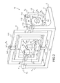
- the figures 1 and 2 represent, in two perspective views, an example of an angular positioning device according to the invention.
- the angular positioning device 1 comprises a frame 2, a first mechanical transmission assembly 10, and a second mechanical transmission assembly 20.
- the first mechanical assembly 10 comprises a first support 11, two connecting rods 12 and 13, and a first actuating device 14.
- the support 11 is in pivot connection with the chassis 2 along a first axis X 1 .
- the first link 12 is in pivot connection with the support 11 along a second axis X 2 , parallel to the axis X 1 .
- the second link 13 is in pivot connection with the first connecting rod 12 along a third axis X 3 , parallel to the axes X 1 and X 2 , and in pivot connection with the chassis 2 along a fourth axis X 4 , parallel to the axes X 1 , X 2 and X 3 .
- the actuating device 14 is able to drive the second link in rotation about the axis X 4 .
- the frame 2 comprises a plate 3 and two arms 4 extending from the plate 3 in a direction orthogonal to the plane of the plate 3.
- the support 11 comprises a rectangular frame 111, and a drive arm 112 extending in a direction orthogonal to the plane of the frame 111. A first end of the drive arm 112 is integral.
- the pivot connection between the support 11 and the frame 2 is made by means of two shafts or pins 113 fixed on the lateral sides of the frame 111 and two bearings 5 formed at the ends of the arms 4.
- the pivot connection between the support 11 and the rod 12 is made at the second end of the drive arm 112.
- the rod 12 comprises a bend at each of its ends so that one end comes to be inserted into a bearing 114 formed in the drive arm 112.
- the other end of the rod 12 is inserted into a bearing 131 formed at one end of the rod 13.
- the actuating device 14 is a rotary engine comprising a s tator integral with the frame 2 and a rotor secured to the second end of the connecting rod 13 and rotating about the axis X 4 .
- the second mechanical transmission unit 20 comprises a second support 21, a connecting arm 22, two links 23 and 24, and a second actuating device 25.
- the second support 21 is in pivot connection with the first support 11 according to a fifth axis X 5 .
- This axis X 5 is not parallel to the axes X 1 to X 4 . It can be, as in the embodiment of the figures 1 and 2 orthogonal to the axes X 1 to X 4 .
- the connecting arm 22 is in pivot connection with the support 21 along an axis X 6 , the orientation of which is discussed below.
- the third connecting rod 23 is in pivot connection with the connecting arm 22 along an axis X 7 , parallel to the axis X 5 .
- the fourth connecting rod 24 is in pivot connection with the third connecting rod 23 along an axis X 8 , and in pivot connection with the chassis 2 along an axis X 9 .
- the X 8 and X 9 axes are parallel to the X 5 and X 7 axes.
- the support 21 comprises a rectangular frame 211 forming part of the frame 111 of the first support 11.
- the pivot connection between the second support 21 and the first support 11 is made by means of two pins 212 fixed on the longitudinal sides of the frame 211 and two bearings 115 formed on the longitudinal sides of the frame 111.
- the pivot connection between the support 21 and the connecting arm 22, the pivot connection between the linkage arm 22 and the connecting rod 23, and the pivot connection between the connecting rods 23 and 24 can each be realized by means of a pin and a bearing cooperating with each other.
- the actuating device 25 is a rotary motor comprising a stator secured to the frame 2 and a rotor secured to the connecting rod 24 and rotating about the axis X 9 . It can also be a stepper motor. The pivot connection between the connecting rod 24 and the frame 2 is thus achieved by the rotary motor.
- each pivot connection could be replaced by a sliding pivot connection having the same axis of rotation or by a ball joint connection.
- the pivot connection between the support 21 and the connecting arm 22, and the pivot connection between the arm 22 and the connecting rod 23 could be combined in a single finger-ball joint between the support 21 and the connecting rod 23 along an axis. orthogonal to the X 6 and X 7 axes.
- the connecting arm 22 is then no longer necessary.
- the finger joint connection could also be replaced by a ball joint or an annular linear connection.
- the angular positioning device according to the invention is controlled by the actuating devices 14 and 25. These actuating devices operate in turn so as to obtain three distinct angular positions for the second support 21.
- This support 21 is suitable receiving an element to be positioned, for example a mirror of an optical instrument.
- the actuating device 14 makes it possible to orient the second support 21 around the axis X 1 . Its actuation rotates the rod 13 around the axis X 4 , which rotates the rod 12 around its instantaneous center of rotation, which itself drives in rotation the drive arm 112 about the axis X 1 , and therefore the frames 111 and 211.
- the first mechanical assembly 10 is configured to take two particular configurations. In each of these configurations, the connecting rods 12 and 13 generate a dead point for the support 11. In general, it is understood by dead point between two connecting rods pivotally connected between them, a particular respective position of these rods for which each element in pivot connection with one of these rods undergoes a reversal of movement when passing through this position.
- the movement can be a rotational or translational movement.
- the rods 12 and 13 generate a dead point for the support 11 when the axis X 3 of the pivot connection between these rods coincides with the plane passing through the axes X 2 and X 4 of the pivot links between the connecting rod 12 and the drive arm 112, and between the connecting rod 13 and the chassis 2, respectively.
- a first neutral point is generated when the X axis 4 is between the X 2 and X 3 axes, as shown in FIGS. figures 1 and 2
- a second neutral point is generated when the X axis 3 is between the axes X 2 and X 4 .
- a dead point could be generated when the X axis 2 is between the axes X 3 and X 4 .
- the direction of rotation of the support 11 is reversed for the same direction of rotation of the actuating device 14. This reversal of the direction of rotation is performed for two angular positions ⁇ 1 and ⁇ 2 of the support 11 around the axis X 1 .
- a continuous rotation of the connecting rod 13 about the axis X 4 causes a rocking movement of the support 11 between the angular positions ⁇ 1 and ⁇ 2 .
- the passage through a neutral position causes a reduction in the transmission ratio between the angular displacement of the rod 13 and that of the support 11.
- the angular positions ⁇ 1 and ⁇ 2 are therefore relatively stable angular positions.
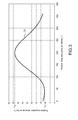
- the figure 3 illustrates, in the form of a graph, the evolution of the angular position of the support 11 as a function of the angular position of the connecting rod 13 for the first mechanical transmission assembly 10 of the figures 1 and 2 .
- This evolution is represented by a curve 31.
- Each angular position is marked with respect to a reference angular position.
- a rotational movement of the connecting rod 13 causes a rotational movement of the support 11 in a first direction of rotation to an angular position ⁇ 1 for which the rods 12 and 13 generate a first neutral.
- the transmission ratio then increases progressively and then decreases again as the angular position ⁇ 1 approaches , the connecting rod 13 having made a complete turn.
- the figure 3 shows that, for a complete revolution of the connecting rod 13, the support 11 oscillates between the angular positions ⁇ 1 and ⁇ 2 .
- the angular displacement between these positions is relatively small, ie about 13 degrees in the embodiment of figures 1 and 2 it is clear that the average transmission ratio between the angular displacement of the connecting rod 13 and the angular displacement of the support 11 is much less than one. Above all, the passage through the dead spots locally causes a significant decrease in the transmission ratio.
- the actuating device 25 makes it possible to orient the second support 21 around the axis X 5 . Its actuation rotates the connecting rod 24 about the axis X 9 , which rotates the connecting rod 23 around its instantaneous center of rotation, which itself drives in rotation the linkage arm 22 and the support 21 around the X axis 5 . It should be noted that the rotation of the support 21 is only possible if the axis X 5 of the pivot connection between the supports 11 and 21 is parallel to the axes X 7 , X 8 and X 9 . The orientation of the axis X 5 depends on the angular position of the support 11 around the axis X 1 .
- the first mechanical assembly 10 is configured so that the X axis 5 is parallel to the X 7 , X 8 and X 9 axes for one of its two dead spots, that is to say when the support 11 is in one of the angular positions ⁇ 1 and ⁇ 2 .
- the orientation of the X axis 5 parallel to the X 7 , X 8 and X 9 axes is thus performed with the maximum accuracy.
- the second mechanical assembly motion transmission 20 is configured to take two particular configurations in each of which the rods 23 and 24 generate a neutral point for the support 21.
- a neutral point is generated for the support 21 when the axis X 8 of the pivot connection between these rods coincides with the plane passing through the axes X 7 and X 9 of the pivot links between the connecting rod 23 and the connecting arm 22, and between the connecting rod 24 and the frame 2, respectively.
- a first neutral point is generated when the X axis 8 is between the X 7 and X 9 axes, as shown in these figures, and a second neutral point is generated when the X axis 9 is between the X axes 7 and X 8 .
- a dead point could be generated when the X axis 7 is between the axes X 8 and X 9 .
- the second mechanical assembly 20 is configured so that the axis X 6 coincides with the axis X 1 for one of its two dead spots, that is to say when the support 21 is in one of the angular positions ⁇ 1 and ⁇ 2 .
- the alignment of the X axis 6 with the axis X 1 is thus performed with the maximum accuracy.
- the angular positioning device is particularly well suited for calibrating an optical instrument.
- An element of the optical instrument for example a mirror, may be attached to the second support.
- the first mechanical motion transmission assembly makes it possible to precisely orient the element for two angular positions around a first axis
- the second mechanical movement transmission assembly makes it possible to orient it precisely for two angular positions around a second axis, not parallel to the first.
- One of the angular positions of interest around the first axis corresponds to one of the angular positions of interest around the second axis, so that the element of the optical instrument is positioned precisely around the first and second axis for three distinct positions.
Landscapes
- Engineering & Computer Science (AREA)
- General Engineering & Computer Science (AREA)
- Physics & Mathematics (AREA)
- Mechanical Engineering (AREA)
- General Physics & Mathematics (AREA)
- Optics & Photonics (AREA)
- Transmission Devices (AREA)
- Mechanical Light Control Or Optical Switches (AREA)
Applications Claiming Priority (1)
| Application Number | Priority Date | Filing Date | Title |
|---|---|---|---|
| FR1202341A FR2995090B1 (fr) | 2012-08-31 | 2012-08-31 | Disposition de positionnement angulaire comprenant deux ensembles mecaniques de transmission de mouvement imbriques a deux points morts chacun |
Publications (2)
| Publication Number | Publication Date |
|---|---|
| EP2706267A1 true EP2706267A1 (de) | 2014-03-12 |
| EP2706267B1 EP2706267B1 (de) | 2015-04-08 |
Family
ID=47664335
Family Applications (1)
| Application Number | Title | Priority Date | Filing Date |
|---|---|---|---|
| EP13180394.2A Active EP2706267B1 (de) | 2012-08-31 | 2013-08-14 | Vorrichtung zur Winkelpositionierung, die zwei mechanische Bewegungsübertragungseinheiten umfasst, die beide jeweils an zwei Totpunkten verschachtelt sind |
Country Status (5)
| Country | Link |
|---|---|
| US (1) | US9086123B2 (de) |
| EP (1) | EP2706267B1 (de) |
| JP (1) | JP6151608B2 (de) |
| ES (1) | ES2541602T3 (de) |
| FR (1) | FR2995090B1 (de) |
Cited By (1)
| Publication number | Priority date | Publication date | Assignee | Title |
|---|---|---|---|---|
| CN107703601A (zh) * | 2017-09-25 | 2018-02-16 | 青岛海信激光显示股份有限公司 | 一种反射镜调节机构 |
Families Citing this family (4)
| Publication number | Priority date | Publication date | Assignee | Title |
|---|---|---|---|---|
| CN106741864B (zh) * | 2016-11-30 | 2021-05-25 | 中国航空工业集团公司沈阳飞机设计研究所 | 一种三功用机械综合运动机构 |
| CN112009710A (zh) * | 2020-09-23 | 2020-12-01 | 袁兴平 | 一种无人机摄像头新型云台结构 |
| US11519549B2 (en) * | 2021-01-26 | 2022-12-06 | CallMe, Inc. | Portable mobile device holder |
| CN113021223B (zh) * | 2021-03-29 | 2022-03-01 | 中国工程物理研究院激光聚变研究中心 | 一种用于大口径平面反射镜的周圈少点夹持框及夹持方法 |
Citations (4)
| Publication number | Priority date | Publication date | Assignee | Title |
|---|---|---|---|---|
| US3026615A (en) * | 1957-11-15 | 1962-03-27 | Giravions Dorand | Guided missile simulator |
| GB1306641A (en) * | 1971-05-05 | 1973-02-14 | Pentacon Dresden Veb | Photographic viewing and printing apparatus |
| FR2234617A1 (de) * | 1973-06-25 | 1975-01-17 | Moderna Butiksinredningar Ab | |
| JP2002148685A (ja) * | 2000-11-08 | 2002-05-22 | Nisca Corp | パンチルトカメラ、及びカメラ用ミラーユニット |
Family Cites Families (11)
| Publication number | Priority date | Publication date | Assignee | Title |
|---|---|---|---|---|
| GB1214715A (en) * | 1968-05-07 | 1970-12-02 | Harry Dudley Wright | Improvements in mechanisms for converting a rotary motion into linear motion |
| US4025193A (en) * | 1974-02-11 | 1977-05-24 | The Boeing Company | Apparatus suitable for use in orienting aircraft in-flight for refueling or other purposes |
| JPS5512425A (en) * | 1978-07-11 | 1980-01-29 | Nippon Electric Co | Adding equipment for stabilization device |
| DE3444230A1 (de) * | 1984-11-30 | 1986-06-12 | Preh, Elektrofeinmechanische Werke Jakob Preh Nachf. Gmbh & Co, 8740 Bad Neustadt | Einstelleinrichtung |
| GB2196753B (en) * | 1986-10-23 | 1990-01-10 | Ferranti Plc | Balanced optical system |
| JP2003018435A (ja) * | 2001-06-28 | 2003-01-17 | Nisca Corp | 首振り装置及びこれを用いた首振りカメラ |
| JP2003018436A (ja) * | 2001-06-28 | 2003-01-17 | Nisca Corp | 首振り装置及びこれを用いた首振りカメラ |
| JP2004153608A (ja) * | 2002-10-31 | 2004-05-27 | Nisca Corp | 首振りカメラ |
| PL2579234T3 (pl) * | 2011-10-07 | 2019-03-29 | E2M Technologies B.V. | Układ platformy ruchomej |
| EP2666727B1 (de) * | 2012-05-24 | 2016-09-07 | MULTIVAC Sepp Haggenmüller SE & Co. KG | Hubeinrichtung für eine Verpackungsmaschine |
| FR2995054B1 (fr) * | 2012-08-31 | 2014-10-03 | Thales Sa | Dispositif de positionnement angulaire a trois points morts |
-
2012
- 2012-08-31 FR FR1202341A patent/FR2995090B1/fr not_active Expired - Fee Related
-
2013
- 2013-08-14 ES ES13180394.2T patent/ES2541602T3/es active Active
- 2013-08-14 EP EP13180394.2A patent/EP2706267B1/de active Active
- 2013-08-20 US US13/971,789 patent/US9086123B2/en active Active
- 2013-08-30 JP JP2013179935A patent/JP6151608B2/ja active Active
Patent Citations (4)
| Publication number | Priority date | Publication date | Assignee | Title |
|---|---|---|---|---|
| US3026615A (en) * | 1957-11-15 | 1962-03-27 | Giravions Dorand | Guided missile simulator |
| GB1306641A (en) * | 1971-05-05 | 1973-02-14 | Pentacon Dresden Veb | Photographic viewing and printing apparatus |
| FR2234617A1 (de) * | 1973-06-25 | 1975-01-17 | Moderna Butiksinredningar Ab | |
| JP2002148685A (ja) * | 2000-11-08 | 2002-05-22 | Nisca Corp | パンチルトカメラ、及びカメラ用ミラーユニット |
Cited By (1)
| Publication number | Priority date | Publication date | Assignee | Title |
|---|---|---|---|---|
| CN107703601A (zh) * | 2017-09-25 | 2018-02-16 | 青岛海信激光显示股份有限公司 | 一种反射镜调节机构 |
Also Published As
| Publication number | Publication date |
|---|---|
| FR2995090A1 (fr) | 2014-03-07 |
| JP6151608B2 (ja) | 2017-06-21 |
| JP2014048668A (ja) | 2014-03-17 |
| US20140060222A1 (en) | 2014-03-06 |
| ES2541602T3 (es) | 2015-07-22 |
| US9086123B2 (en) | 2015-07-21 |
| FR2995090B1 (fr) | 2014-09-26 |
| EP2706267B1 (de) | 2015-04-08 |
Similar Documents
| Publication | Publication Date | Title |
|---|---|---|
| EP3326263B1 (de) | Kompakter getriebemotor | |
| EP2706267B1 (de) | Vorrichtung zur Winkelpositionierung, die zwei mechanische Bewegungsübertragungseinheiten umfasst, die beide jeweils an zwei Totpunkten verschachtelt sind | |
| EP0055720B1 (de) | Vorrichtung zur orientierung und einstellung einer nutzlast | |
| EP2288477B1 (de) | Motorisiertes gelenk mit zwei drehverbindungen und das gelenk einsetzender humanoidroboter | |
| EP2781009B1 (de) | Anzeigemodul für ein armaturenbrett mit flüssigkeitsbewegung | |
| FR2817212A1 (fr) | Lampe de vehicule et appareil d'entrainement en rotation d'un dispositif optique | |
| CA2466893A1 (fr) | Mecanisme articule comprenant un reducteur a cable utilisable dans un bras de robot | |
| FR2672836A1 (fr) | Dispositif d'articulation a structure parallele et appareils de transmission de mouvement a distance en faisant application. | |
| EP2373460A1 (de) | Motorisierte vorrichtung mit einer modularen anordnung | |
| EP2703691B1 (de) | Vorrichtung zur Winkeleinstellung mit drei Totpunkten | |
| FR2761286A1 (fr) | Positionneur multiaxe | |
| EP1964778A1 (de) | Drehgelenk mit Blattfedern | |
| EP3543588A1 (de) | Vorrichtung zur winkeleinstellung | |
| EP0056550B1 (de) | Vorrichtung zum Ausrichten nach zwei senkrechten Achsen, insbesondere für eine Mikrowellenantenne | |
| EP2741406A1 (de) | Schrittschaltmotor mit Doppelrotor | |
| FR2885688A1 (fr) | Actionneur pour indicateurs de mesures | |
| CA2060773C (fr) | Dispositif de support et d'entrainement en rotation d'une charge utile par rapport a une structure, notamment pour un mecanisme de pointage d'antenne de satellite | |
| FR2490335A1 (fr) | Horizon artificiel pour aeronef | |
| EP3839604B1 (de) | Verbesserte exzentrische scan-vorrichtung | |
| EP4401926B1 (de) | Neue architektur für ein mobiles robotersystem | |
| EP0455543B1 (de) | Vorrichtung zur Ausrichtung einer Reflektorantenne | |
| CH721639A2 (fr) | Mécanisme de transformation d'un mouvement rotatif en translation et inversement, dispositif d'affichage et pièce d'horlogerie | |
| FR2615000A1 (fr) | Dispositif de deviation de faisceau lumineux et systeme d'asservissement en comportant application | |
| FR2571906A1 (fr) | Moteur-couple a deux etages | |
| FR2663789A1 (fr) | Dispositif de deplacement d'un organe et application au pointage d'un reflecteur d'antenne. |
Legal Events
| Date | Code | Title | Description |
|---|---|---|---|
| PUAI | Public reference made under article 153(3) epc to a published international application that has entered the european phase |
Free format text: ORIGINAL CODE: 0009012 |
|
| AK | Designated contracting states |
Kind code of ref document: A1 Designated state(s): AL AT BE BG CH CY CZ DE DK EE ES FI FR GB GR HR HU IE IS IT LI LT LU LV MC MK MT NL NO PL PT RO RS SE SI SK SM TR |
|
| AX | Request for extension of the european patent |
Extension state: BA ME |
|
| REG | Reference to a national code |
Ref country code: DE Ref legal event code: R079 Ref document number: 602013001453 Country of ref document: DE Free format text: PREVIOUS MAIN CLASS: F16H0021520000 Ipc: G02B0007182000 |
|
| GRAP | Despatch of communication of intention to grant a patent |
Free format text: ORIGINAL CODE: EPIDOSNIGR1 |
|
| 17P | Request for examination filed |
Effective date: 20140912 |
|
| RBV | Designated contracting states (corrected) |
Designated state(s): AL AT BE BG CH CY CZ DE DK EE ES FI FR GB GR HR HU IE IS IT LI LT LU LV MC MK MT NL NO PL PT RO RS SE SI SK SM TR |
|
| RIC1 | Information provided on ipc code assigned before grant |
Ipc: G02B 7/182 20060101AFI20140926BHEP Ipc: F16H 21/52 20060101ALI20140926BHEP Ipc: F16M 11/18 20060101ALI20140926BHEP |
|
| INTG | Intention to grant announced |
Effective date: 20141017 |
|
| RIN1 | Information on inventor provided before grant (corrected) |
Inventor name: VEZAIN, STEPHANE Inventor name: GUIONIE, M. SEBASTIEN Inventor name: BAUDASSE, YANNICK |
|
| GRAS | Grant fee paid |
Free format text: ORIGINAL CODE: EPIDOSNIGR3 |
|
| GRAA | (expected) grant |
Free format text: ORIGINAL CODE: 0009210 |
|
| AK | Designated contracting states |
Kind code of ref document: B1 Designated state(s): AL AT BE BG CH CY CZ DE DK EE ES FI FR GB GR HR HU IE IS IT LI LT LU LV MC MK MT NL NO PL PT RO RS SE SI SK SM TR |
|
| REG | Reference to a national code |
Ref country code: GB Ref legal event code: FG4D Free format text: NOT ENGLISH |
|
| REG | Reference to a national code |
Ref country code: CH Ref legal event code: EP |
|
| REG | Reference to a national code |
Ref country code: IE Ref legal event code: FG4D Free format text: LANGUAGE OF EP DOCUMENT: FRENCH |
|
| REG | Reference to a national code |
Ref country code: AT Ref legal event code: REF Ref document number: 720992 Country of ref document: AT Kind code of ref document: T Effective date: 20150515 |
|
| REG | Reference to a national code |
Ref country code: DE Ref legal event code: R096 Ref document number: 602013001453 Country of ref document: DE Effective date: 20150521 |
|
| REG | Reference to a national code |
Ref country code: CH Ref legal event code: NV Representative=s name: MARKS AND CLERK (LUXEMBOURG) LLP, CH |
|
| REG | Reference to a national code |
Ref country code: NL Ref legal event code: T3 Ref country code: ES Ref legal event code: FG2A Ref document number: 2541602 Country of ref document: ES Kind code of ref document: T3 Effective date: 20150722 |
|
| REG | Reference to a national code |
Ref country code: NL Ref legal event code: T3 |
|
| REG | Reference to a national code |
Ref country code: AT Ref legal event code: MK05 Ref document number: 720992 Country of ref document: AT Kind code of ref document: T Effective date: 20150408 |
|
| REG | Reference to a national code |
Ref country code: LT Ref legal event code: MG4D |
|
| PG25 | Lapsed in a contracting state [announced via postgrant information from national office to epo] |
Ref country code: NO Free format text: LAPSE BECAUSE OF FAILURE TO SUBMIT A TRANSLATION OF THE DESCRIPTION OR TO PAY THE FEE WITHIN THE PRESCRIBED TIME-LIMIT Effective date: 20150708 Ref country code: PT Free format text: LAPSE BECAUSE OF FAILURE TO SUBMIT A TRANSLATION OF THE DESCRIPTION OR TO PAY THE FEE WITHIN THE PRESCRIBED TIME-LIMIT Effective date: 20150810 Ref country code: LT Free format text: LAPSE BECAUSE OF FAILURE TO SUBMIT A TRANSLATION OF THE DESCRIPTION OR TO PAY THE FEE WITHIN THE PRESCRIBED TIME-LIMIT Effective date: 20150408 Ref country code: HR Free format text: LAPSE BECAUSE OF FAILURE TO SUBMIT A TRANSLATION OF THE DESCRIPTION OR TO PAY THE FEE WITHIN THE PRESCRIBED TIME-LIMIT Effective date: 20150408 Ref country code: FI Free format text: LAPSE BECAUSE OF FAILURE TO SUBMIT A TRANSLATION OF THE DESCRIPTION OR TO PAY THE FEE WITHIN THE PRESCRIBED TIME-LIMIT Effective date: 20150408 |
|
| PG25 | Lapsed in a contracting state [announced via postgrant information from national office to epo] |
Ref country code: GR Free format text: LAPSE BECAUSE OF FAILURE TO SUBMIT A TRANSLATION OF THE DESCRIPTION OR TO PAY THE FEE WITHIN THE PRESCRIBED TIME-LIMIT Effective date: 20150709 Ref country code: RS Free format text: LAPSE BECAUSE OF FAILURE TO SUBMIT A TRANSLATION OF THE DESCRIPTION OR TO PAY THE FEE WITHIN THE PRESCRIBED TIME-LIMIT Effective date: 20150408 Ref country code: LV Free format text: LAPSE BECAUSE OF FAILURE TO SUBMIT A TRANSLATION OF THE DESCRIPTION OR TO PAY THE FEE WITHIN THE PRESCRIBED TIME-LIMIT Effective date: 20150408 Ref country code: IS Free format text: LAPSE BECAUSE OF FAILURE TO SUBMIT A TRANSLATION OF THE DESCRIPTION OR TO PAY THE FEE WITHIN THE PRESCRIBED TIME-LIMIT Effective date: 20150808 Ref country code: AT Free format text: LAPSE BECAUSE OF FAILURE TO SUBMIT A TRANSLATION OF THE DESCRIPTION OR TO PAY THE FEE WITHIN THE PRESCRIBED TIME-LIMIT Effective date: 20150408 |
|
| REG | Reference to a national code |
Ref country code: DE Ref legal event code: R097 Ref document number: 602013001453 Country of ref document: DE |
|
| PG25 | Lapsed in a contracting state [announced via postgrant information from national office to epo] |
Ref country code: DK Free format text: LAPSE BECAUSE OF FAILURE TO SUBMIT A TRANSLATION OF THE DESCRIPTION OR TO PAY THE FEE WITHIN THE PRESCRIBED TIME-LIMIT Effective date: 20150408 Ref country code: EE Free format text: LAPSE BECAUSE OF FAILURE TO SUBMIT A TRANSLATION OF THE DESCRIPTION OR TO PAY THE FEE WITHIN THE PRESCRIBED TIME-LIMIT Effective date: 20150408 |
|
| PLBE | No opposition filed within time limit |
Free format text: ORIGINAL CODE: 0009261 |
|
| STAA | Information on the status of an ep patent application or granted ep patent |
Free format text: STATUS: NO OPPOSITION FILED WITHIN TIME LIMIT |
|
| PG25 | Lapsed in a contracting state [announced via postgrant information from national office to epo] |
Ref country code: SK Free format text: LAPSE BECAUSE OF FAILURE TO SUBMIT A TRANSLATION OF THE DESCRIPTION OR TO PAY THE FEE WITHIN THE PRESCRIBED TIME-LIMIT Effective date: 20150408 Ref country code: CZ Free format text: LAPSE BECAUSE OF FAILURE TO SUBMIT A TRANSLATION OF THE DESCRIPTION OR TO PAY THE FEE WITHIN THE PRESCRIBED TIME-LIMIT Effective date: 20150408 Ref country code: PL Free format text: LAPSE BECAUSE OF FAILURE TO SUBMIT A TRANSLATION OF THE DESCRIPTION OR TO PAY THE FEE WITHIN THE PRESCRIBED TIME-LIMIT Effective date: 20150408 Ref country code: RO Free format text: LAPSE BECAUSE OF NON-PAYMENT OF DUE FEES Effective date: 20150408 |
|
| 26N | No opposition filed |
Effective date: 20160111 |
|
| PG25 | Lapsed in a contracting state [announced via postgrant information from national office to epo] |
Ref country code: MC Free format text: LAPSE BECAUSE OF FAILURE TO SUBMIT A TRANSLATION OF THE DESCRIPTION OR TO PAY THE FEE WITHIN THE PRESCRIBED TIME-LIMIT Effective date: 20150408 Ref country code: LU Free format text: LAPSE BECAUSE OF FAILURE TO SUBMIT A TRANSLATION OF THE DESCRIPTION OR TO PAY THE FEE WITHIN THE PRESCRIBED TIME-LIMIT Effective date: 20150814 |
|
| PG25 | Lapsed in a contracting state [announced via postgrant information from national office to epo] |
Ref country code: SI Free format text: LAPSE BECAUSE OF FAILURE TO SUBMIT A TRANSLATION OF THE DESCRIPTION OR TO PAY THE FEE WITHIN THE PRESCRIBED TIME-LIMIT Effective date: 20150408 |
|
| REG | Reference to a national code |
Ref country code: IE Ref legal event code: MM4A |
|
| PG25 | Lapsed in a contracting state [announced via postgrant information from national office to epo] |
Ref country code: IE Free format text: LAPSE BECAUSE OF NON-PAYMENT OF DUE FEES Effective date: 20150814 |
|
| REG | Reference to a national code |
Ref country code: FR Ref legal event code: PLFP Year of fee payment: 4 |
|
| PG25 | Lapsed in a contracting state [announced via postgrant information from national office to epo] |
Ref country code: MT Free format text: LAPSE BECAUSE OF FAILURE TO SUBMIT A TRANSLATION OF THE DESCRIPTION OR TO PAY THE FEE WITHIN THE PRESCRIBED TIME-LIMIT Effective date: 20150408 |
|
| PG25 | Lapsed in a contracting state [announced via postgrant information from national office to epo] |
Ref country code: BG Free format text: LAPSE BECAUSE OF FAILURE TO SUBMIT A TRANSLATION OF THE DESCRIPTION OR TO PAY THE FEE WITHIN THE PRESCRIBED TIME-LIMIT Effective date: 20150408 Ref country code: HU Free format text: LAPSE BECAUSE OF FAILURE TO SUBMIT A TRANSLATION OF THE DESCRIPTION OR TO PAY THE FEE WITHIN THE PRESCRIBED TIME-LIMIT; INVALID AB INITIO Effective date: 20130814 |
|
| PG25 | Lapsed in a contracting state [announced via postgrant information from national office to epo] |
Ref country code: SE Free format text: LAPSE BECAUSE OF FAILURE TO SUBMIT A TRANSLATION OF THE DESCRIPTION OR TO PAY THE FEE WITHIN THE PRESCRIBED TIME-LIMIT Effective date: 20150408 Ref country code: CY Free format text: LAPSE BECAUSE OF FAILURE TO SUBMIT A TRANSLATION OF THE DESCRIPTION OR TO PAY THE FEE WITHIN THE PRESCRIBED TIME-LIMIT Effective date: 20150408 |
|
| REG | Reference to a national code |
Ref country code: FR Ref legal event code: PLFP Year of fee payment: 5 |
|
| PG25 | Lapsed in a contracting state [announced via postgrant information from national office to epo] |
Ref country code: BE Free format text: LAPSE BECAUSE OF NON-PAYMENT OF DUE FEES Effective date: 20150831 |
|
| PG25 | Lapsed in a contracting state [announced via postgrant information from national office to epo] |
Ref country code: SM Free format text: LAPSE BECAUSE OF FAILURE TO SUBMIT A TRANSLATION OF THE DESCRIPTION OR TO PAY THE FEE WITHIN THE PRESCRIBED TIME-LIMIT Effective date: 20150408 |
|
| PG25 | Lapsed in a contracting state [announced via postgrant information from national office to epo] |
Ref country code: MK Free format text: LAPSE BECAUSE OF FAILURE TO SUBMIT A TRANSLATION OF THE DESCRIPTION OR TO PAY THE FEE WITHIN THE PRESCRIBED TIME-LIMIT Effective date: 20150408 Ref country code: TR Free format text: LAPSE BECAUSE OF FAILURE TO SUBMIT A TRANSLATION OF THE DESCRIPTION OR TO PAY THE FEE WITHIN THE PRESCRIBED TIME-LIMIT Effective date: 20150408 |
|
| REG | Reference to a national code |
Ref country code: FR Ref legal event code: PLFP Year of fee payment: 6 |
|
| PG25 | Lapsed in a contracting state [announced via postgrant information from national office to epo] |
Ref country code: AL Free format text: LAPSE BECAUSE OF FAILURE TO SUBMIT A TRANSLATION OF THE DESCRIPTION OR TO PAY THE FEE WITHIN THE PRESCRIBED TIME-LIMIT Effective date: 20150408 |
|
| PGFP | Annual fee paid to national office [announced via postgrant information from national office to epo] |
Ref country code: NL Payment date: 20250724 Year of fee payment: 13 |
|
| PGFP | Annual fee paid to national office [announced via postgrant information from national office to epo] |
Ref country code: ES Payment date: 20250902 Year of fee payment: 13 |
|
| PGFP | Annual fee paid to national office [announced via postgrant information from national office to epo] |
Ref country code: DE Payment date: 20250716 Year of fee payment: 13 |
|
| PGFP | Annual fee paid to national office [announced via postgrant information from national office to epo] |
Ref country code: IT Payment date: 20250728 Year of fee payment: 13 |
|
| PGFP | Annual fee paid to national office [announced via postgrant information from national office to epo] |
Ref country code: GB Payment date: 20250717 Year of fee payment: 13 |
|
| PGFP | Annual fee paid to national office [announced via postgrant information from national office to epo] |
Ref country code: FR Payment date: 20250721 Year of fee payment: 13 |
|
| PGFP | Annual fee paid to national office [announced via postgrant information from national office to epo] |
Ref country code: CH Payment date: 20250901 Year of fee payment: 13 |