EP2708859A1 - System and method for determining volume of material in a tank - Google Patents
System and method for determining volume of material in a tank Download PDFInfo
- Publication number
- EP2708859A1 EP2708859A1 EP13183191.9A EP13183191A EP2708859A1 EP 2708859 A1 EP2708859 A1 EP 2708859A1 EP 13183191 A EP13183191 A EP 13183191A EP 2708859 A1 EP2708859 A1 EP 2708859A1
- Authority
- EP
- European Patent Office
- Prior art keywords
- tank
- sensors
- controller
- distance
- volume
- Prior art date
- Legal status (The legal status is an assumption and is not a legal conclusion. Google has not performed a legal analysis and makes no representation as to the accuracy of the status listed.)
- Withdrawn
Links
- 239000000463 material Substances 0.000 title claims abstract description 79
- 238000000034 method Methods 0.000 title claims abstract description 9
- 238000010586 diagram Methods 0.000 description 2
- 239000003337 fertilizer Substances 0.000 description 2
- 239000003905 agrochemical Substances 0.000 description 1
- 230000009286 beneficial effect Effects 0.000 description 1
- 238000001514 detection method Methods 0.000 description 1
- 239000000428 dust Substances 0.000 description 1
- 238000005516 engineering process Methods 0.000 description 1
- 239000008187 granular material Substances 0.000 description 1
- 238000005259 measurement Methods 0.000 description 1
- 238000012986 modification Methods 0.000 description 1
- 230000004048 modification Effects 0.000 description 1
- PHPUXYRXPHEJDF-UHFFFAOYSA-N oxyphenisatine acetate Chemical compound C1=CC(OC(=O)C)=CC=C1C1(C=2C=CC(OC(C)=O)=CC=2)C2=CC=CC=C2NC1=O PHPUXYRXPHEJDF-UHFFFAOYSA-N 0.000 description 1
- 238000007789 sealing Methods 0.000 description 1
- 238000001228 spectrum Methods 0.000 description 1
Images


Classifications
-
- G—PHYSICS
- G01—MEASURING; TESTING
- G01F—MEASURING VOLUME, VOLUME FLOW, MASS FLOW OR LIQUID LEVEL; METERING BY VOLUME
- G01F23/00—Indicating or measuring liquid level or level of fluent solid material, e.g. indicating in terms of volume or indicating by means of an alarm
- G01F23/22—Indicating or measuring liquid level or level of fluent solid material, e.g. indicating in terms of volume or indicating by means of an alarm by measuring physical variables, other than linear dimensions, pressure or weight, dependent on the level to be measured, e.g. by difference of heat transfer of steam or water
- G01F23/28—Indicating or measuring liquid level or level of fluent solid material, e.g. indicating in terms of volume or indicating by means of an alarm by measuring physical variables, other than linear dimensions, pressure or weight, dependent on the level to be measured, e.g. by difference of heat transfer of steam or water by measuring the variations of parameters of electromagnetic or acoustic waves applied directly to the liquid or fluent solid material
-
- A—HUMAN NECESSITIES
- A01—AGRICULTURE; FORESTRY; ANIMAL HUSBANDRY; HUNTING; TRAPPING; FISHING
- A01C—PLANTING; SOWING; FERTILISING
- A01C15/00—Fertiliser distributors
- A01C15/005—Undercarriages, tanks, hoppers, stirrers specially adapted for seeders or fertiliser distributors
- A01C15/006—Hoppers
Definitions
- the invention relates to a system for determining volume of material in a tank, the system comprising: one or more sensors positioned above a quantity of material in a tank.
- the invention further comprises a method of measuring a quantity of material in a tank.
- Material level sensors have been used to indicate the level. Such sensors have been used to detect when the level drops below a certain point or points, such as one-quarter full, half full or three quarters full. Video cameras have also been used to allow a machine operator to see the material level in the tank during operation.
- the level of material in a tank can also be determined using an ultrasonic or infrared distance sensor to measure the distance from the sensor at the top of the tank to the surface of the material, usually at a single point. Such a sensor can be used to provide real time data of the height of the material in the tank.
- a system of above mentioned type comprises that the sensors are adapted to detect the distance between the sensors and the surface of the material at multiple locations, the sensors generating output signals indicative of the distance from the sensors to the material surface at the multiple locations; a controller receiving the sensor output signals, the controller adapted to determine a surface profile of the material and the controller adapted to determine the volume of material in the tank using the surface profile and stored data regarding the tank shape.
- a method of measuring a quantity of material in a tank comprises the steps of providing one or more sensors adapted to be positioned above a quantity of material in a tank, the sensors adapted to detect the distance between the sensors and the surface of the material at multiple locations, the sensors generating output signals indicative of the distance between the sensors and the surface of the material at the multiple locations; providing a controller adapted to receive the sensor output signals, the controller adapted to determine a surface profile of the material and the controller adapted to determine the volume of material in the tank using the surface profile and stored data regarding the tank shape; operating the sensors to determine the distance between the sensors and the surface of the material at the multiple locations and generating the output signals indicative of the distance between the sensors and the surface of the material at the multiple locations; receiving the output signals at the controller; and using the controller to determine a material surface and material volume.
- FIG. 1 shows an agricultural implement such as an air seeder 2.
- the air seeder 2 comprises a commodity cart 4 towed between a tractor (not shown) and a tilling implement 6.
- the commodity cart 4 has a frame 10 upon which the product tanks 8 and 9 and wheels 12 are mounted.
- Each product tank has a door 3 releasably sealing an opening 5 (shown in Figs 2 and 5 ) at its upper end for filling the tank with product.
- a metering system 14 is provided at the lower end of each tank (only one of which is shown) for controlled feeding of product (in this case, granular material) into a pneumatic distribution system 16 at a primary distribution manifold 18.
- the tilling implement 8, towed behind the commodity cart 4 includes a frame 20 to which ground openers 22 and packers 24 are mounted.
- the pneumatic distribution system 16 includes a centrifugal fan 26 which is connected to a plenum 28, which is in turn connected by distribution lines 30 to one or more primary distribution manifolds 18, each associated with a product tank 8 or 9.
- the primary distribution manifolds 18 are connected by distribution lines 30 to a dimpled riser tube 32, which is coupled to a secondary distribution header 34.
- Secondary distribution lines 36 connect the secondary distribution header 34 to seed boots 38 mounted on the ground openers 22.
- the secondary distribution headers 34 divide the product substantially evenly into a series of the distribution lines 36 leading to the seed boots 38 on the ground openers 22.
- Fig. 2 is a top view of the tank 8. The door at the upper opening 5 is not shown.
- the top of the tank has been equipped with five distance sensors 50.
- the sensors 50 are used to measure the distance from the sensors to the surface 44 of the material 42 as shown in Fig. 3 .
- the sight-lines of the three sensors 50 on the center-line are shown as dashed lines 52.
- the sensors 50 are coupled to controller 56 as shown in Fig. 4 to communicate the output signals of the sensors to the controller.
- the controller uses the distance data from the sensors to the material surface 44 to create a surface profile of the material. The more sensors that are used, the more accurate will be the generated surface profile. While five sensors are shown in Fig. 2 , five to ten sensors will produce an accurate surface profile in most air seeder applications.
- the sensors 50 can be ultrasonic, infrared or any other distance measuring sensor suitable for use with seed, fertilizer and other agricultural chemicals.
- the need to operate in a dust filled environment may be a factor in the choice of sensor type.
- a three dimensional laser scanner or camera may also be used but adds considerable cost.
- the controller uses the profile and stored data on the size and configuration of the tank 8 to calculate the volume of material in the tank. It is this step that moves beyond mere knowledge of the material height at one or more locations to actual knowledge of the quantity of material in the tank. If the density of the material is known, the weight can then be calculated once the volume is determined. Density information can be stored in a memory using nominal values for different materials. Alternatively, after a known weight of material is supplied to the tank, the surface profile can be determined from distance measurement, the volume calculated and then the density calculated. Operation of the machine may result in compacting of the material thereby increasing the density. This must be accounted for.
- the use of sensors to generate a surface profile and from there to calculate volume and weight overcomes the limitations on the use of load cells described above.
- Fig. 2 Multiple sensors as shown in Fig. 2 require a wiring harness to connect the sensors to the controller, adding to the cost and complexity of the system. Cost and complexity can be reduced by using a single sensor that measures the distance to multiple points on the material surface.
- One type of relatively low cost sensor is a 2-dimensional camera multiple point active auto-focus sensor.
- a single sensor 60 is provided at the top of the tank 8 which measures the distance to the surface 44 at multiple locations. The various lines along with the sensor detects the distance to the surface 44 are shown by the dashed lines 62.
- the number of detection points can be any number desired to achieve the desired accuracy but likely five to nine points will be sufficient in the context of an agricultural air seeder tank.
- Low to midrange consumer cameras typically have three to nine focus points where the sensor determines the distance from the camera to each point. Higher end cameras may have many more focus points.
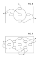
- Camera auto-focus sensors typically have the focus points arranged in a grid pattern as shown in Fig. 6 with five sensor points 54 or as shown in Fig. 7 with nine sensor points 54. By providing distance information to multiple points, the sensor offers information similar to a 3-dimension camera.
- the sensor output signals are communicated to a controller 56 as shown in Fig. 4 .
- a sensor can determine distance, including ultrasonic sound waves and infrared light.
- sound waves are emitted from the sensor, and by measuring the delay in the reflection of the sound waves, distance to the subject is calculated.
- Several cameras, including the Polaroid Spectra and SX-70 apply an ultrasonic auto-focus sensor.
- the infrared light is usually used to triangulate the distance to the subject.
- Compact cameras including the Nikon 35TiQD and 28TiQD, the Canon AF35M, and the Contax T2 and T3 use an infrared system.
- Other methods of determining the distance to the object instead of triangulation are the time of flight for the reflected signal and the amount of infrared light reflected from the subject.
- the output signals from the multiple point sensor 60 are communicated to the controller 56.
- the controller is programmed or configured to receive the distance data from the sensor 60 and determine a profile of the material surface 44. Using the surface profile and stored data on the tank shape, the controller then determines the volume of material in the tank. Material volume can be converted to material weight using density information.
Landscapes
- Physics & Mathematics (AREA)
- Life Sciences & Earth Sciences (AREA)
- Soil Sciences (AREA)
- Fluid Mechanics (AREA)
- General Physics & Mathematics (AREA)
- Thermal Sciences (AREA)
- Electromagnetism (AREA)
- Environmental Sciences (AREA)
- Length Measuring Devices By Optical Means (AREA)
- Measurement Of Levels Of Liquids Or Fluent Solid Materials (AREA)
- Fertilizing (AREA)
- Sowing (AREA)
- Length Measuring Devices With Unspecified Measuring Means (AREA)
Abstract
Description
- The invention relates to a system for determining volume of material in a tank, the system comprising: one or more sensors positioned above a quantity of material in a tank. The invention further comprises a method of measuring a quantity of material in a tank.
- When distributing material from a tank, it is often beneficial to know the quantity of material in the tank. One such material distribution application is in the context of an agricultural air seeder. It is important to know when the material, such as seed or fertilizer, will be exhausted so the machine can be resupplied. Material level sensors have been used to indicate the level. Such sensors have been used to detect when the level drops below a certain point or points, such as one-quarter full, half full or three quarters full. Video cameras have also been used to allow a machine operator to see the material level in the tank during operation. The level of material in a tank can also be determined using an ultrasonic or infrared distance sensor to measure the distance from the sensor at the top of the tank to the surface of the material, usually at a single point. Such a sensor can be used to provide real time data of the height of the material in the tank.
- While knowledge of the material level in the tank is useful to determine when to resupply the tank, this is of limited value. More useful is knowledge of the actual quantity of material in the tank. Recent advances in technology have used load cells supporting a tank to continuously measure the weight of material in a tank. However, the ability to accurately weigh a tank or container requires that each tank be separated from other tanks and scales cannot be used with multiple compartment tanks. Knowing the exact quantity of material in the tank in real time can be useful in automatic meter calibration without a separate calibration procedure with the machine stopped.
- It is therefore an object of the invention to overcome above mention problems.
- The object will be achieved by the teaching of
independent claims 1 and 7. Further advantageous solutions will be defined in the accompanying claims. - Accordingly, a system of above mentioned type comprises that the sensors are adapted to detect the distance between the sensors and the surface of the material at multiple locations, the sensors generating output signals indicative of the distance from the sensors to the material surface at the multiple locations; a controller receiving the sensor output signals, the controller adapted to determine a surface profile of the material and the controller adapted to determine the volume of material in the tank using the surface profile and stored data regarding the tank shape. Further a method of measuring a quantity of material in a tank comprises the steps of providing one or more sensors adapted to be positioned above a quantity of material in a tank, the sensors adapted to detect the distance between the sensors and the surface of the material at multiple locations, the sensors generating output signals indicative of the distance between the sensors and the surface of the material at the multiple locations; providing a controller adapted to receive the sensor output signals, the controller adapted to determine a surface profile of the material and the controller adapted to determine the volume of material in the tank using the surface profile and stored data regarding the tank shape; operating the sensors to determine the distance between the sensors and the surface of the material at the multiple locations and generating the output signals indicative of the distance between the sensors and the surface of the material at the multiple locations; receiving the output signals at the controller; and using the controller to determine a material surface and material volume.
-
Fig. 1 is a side elevational view of an air seeder having an air cart and tool; -
Fig. 2 is a top view of the air cart tank illustrating multiple sensors at the top of the tank; -
Fig. 3 is a sectional view of the air cart tank as seen along the line 3-3 ofFig. 2 ; -
Fig. 4 is a schematic diagram of a control circuit; -
Fig. 5 is another sectional view of the air cart tank likeFig. 3 illustrating another embodiment; and -
Figs. 6 and 7 are diagrams showing multiple focus points for camera auto-focus sensors; -
FIG. 1 shows an agricultural implement such as anair seeder 2. Theair seeder 2 comprises a commodity cart 4 towed between a tractor (not shown) and a tilling implement 6. The commodity cart 4 has aframe 10 upon which theproduct tanks 8 and 9 andwheels 12 are mounted. Each product tank has adoor 3 releasably sealing an opening 5 (shown inFigs 2 and5 ) at its upper end for filling the tank with product. Ametering system 14 is provided at the lower end of each tank (only one of which is shown) for controlled feeding of product (in this case, granular material) into apneumatic distribution system 16 at aprimary distribution manifold 18. The tilling implement 8, towed behind the commodity cart 4, includes aframe 20 to whichground openers 22 andpackers 24 are mounted. - The
pneumatic distribution system 16 includes acentrifugal fan 26 which is connected to aplenum 28, which is in turn connected bydistribution lines 30 to one or moreprimary distribution manifolds 18, each associated with aproduct tank 8 or 9. Theprimary distribution manifolds 18 are connected bydistribution lines 30 to adimpled riser tube 32, which is coupled to asecondary distribution header 34.Secondary distribution lines 36 connect thesecondary distribution header 34 toseed boots 38 mounted on theground openers 22. - During operation of the
air seeder 2, air and product flow in thepneumatic distribution system 16 from theprimary distribution manifold 18 throughdistribution lines 30 to thedimpled riser tubes 32 which attempt to randomize distribution of product from thesecondary distribution headers 34 which are immediately downstream. Thesecondary distribution headers 34 divide the product substantially evenly into a series of thedistribution lines 36 leading to theseed boots 38 on theground openers 22. -
Fig. 2 is a top view of thetank 8. The door at theupper opening 5 is not shown. The top of the tank has been equipped with fivedistance sensors 50. Thesensors 50 are used to measure the distance from the sensors to thesurface 44 of thematerial 42 as shown inFig. 3 . The sight-lines of the threesensors 50 on the center-line are shown as dashedlines 52. Thesensors 50 are coupled tocontroller 56 as shown inFig. 4 to communicate the output signals of the sensors to the controller. The controller uses the distance data from the sensors to thematerial surface 44 to create a surface profile of the material. The more sensors that are used, the more accurate will be the generated surface profile. While five sensors are shown inFig. 2 , five to ten sensors will produce an accurate surface profile in most air seeder applications. Thesensors 50 can be ultrasonic, infrared or any other distance measuring sensor suitable for use with seed, fertilizer and other agricultural chemicals. The need to operate in a dust filled environment may be a factor in the choice of sensor type. A three dimensional laser scanner or camera may also be used but adds considerable cost. - Once the profile of the
surface 44 is created from the sensor data, the controller uses the profile and stored data on the size and configuration of thetank 8 to calculate the volume of material in the tank. It is this step that moves beyond mere knowledge of the material height at one or more locations to actual knowledge of the quantity of material in the tank. If the density of the material is known, the weight can then be calculated once the volume is determined. Density information can be stored in a memory using nominal values for different materials. Alternatively, after a known weight of material is supplied to the tank, the surface profile can be determined from distance measurement, the volume calculated and then the density calculated. Operation of the machine may result in compacting of the material thereby increasing the density. This must be accounted for. The use of sensors to generate a surface profile and from there to calculate volume and weight, overcomes the limitations on the use of load cells described above. - Multiple sensors as shown in
Fig. 2 require a wiring harness to connect the sensors to the controller, adding to the cost and complexity of the system. Cost and complexity can be reduced by using a single sensor that measures the distance to multiple points on the material surface. One type of relatively low cost sensor is a 2-dimensional camera multiple point active auto-focus sensor. With reference toFig. 5 , asingle sensor 60 is provided at the top of thetank 8 which measures the distance to thesurface 44 at multiple locations. The various lines along with the sensor detects the distance to thesurface 44 are shown by thedashed lines 62. The number of detection points can be any number desired to achieve the desired accuracy but likely five to nine points will be sufficient in the context of an agricultural air seeder tank. - Low to midrange consumer cameras typically have three to nine focus points where the sensor determines the distance from the camera to each point. Higher end cameras may have many more focus points. Camera auto-focus sensors typically have the focus points arranged in a grid pattern as shown in
Fig. 6 with fivesensor points 54 or as shown inFig. 7 with nine sensor points 54. By providing distance information to multiple points, the sensor offers information similar to a 3-dimension camera. The sensor output signals are communicated to acontroller 56 as shown inFig. 4 . - There are various ways a sensor can determine distance, including ultrasonic sound waves and infrared light. In the first case, sound waves are emitted from the sensor, and by measuring the delay in the reflection of the sound waves, distance to the subject is calculated. Several cameras, including the Polaroid Spectra and SX-70 apply an ultrasonic auto-focus sensor. In the case of an infrared sensor, the infrared light is usually used to triangulate the distance to the subject. Compact cameras including the Nikon 35TiQD and 28TiQD, the Canon AF35M, and the Contax T2 and T3 use an infrared system. Other methods of determining the distance to the object instead of triangulation are the time of flight for the reflected signal and the amount of infrared light reflected from the subject.
- As with the
multiple sensors 50 above, the output signals from themultiple point sensor 60 are communicated to thecontroller 56. The controller is programmed or configured to receive the distance data from thesensor 60 and determine a profile of thematerial surface 44. Using the surface profile and stored data on the tank shape, the controller then determines the volume of material in the tank. Material volume can be converted to material weight using density information. - Having described the preferred embodiment, it will become apparent that various modifications can be made without departing from the scope of the invention as defined in the accompanying claims.
Claims (8)
- A system for determining volume of material in a tank (8, 9), the system comprising: one or more sensors (50, 60) positioned above a quantity of material (42) in a tank (8, 9), characterized in that the sensors (50, 60) are adapted to detect the distance between the sensors (50, 60) and the surface (44) of the material (42) at multiple locations, the sensors (50, 60) generating output signals indicative of the distance from the sensors (50, 60) to the material surface (44) at the multiple locations; a controller (56) receiving the sensor output signals, the controller (56) adapted to determine a surface profile of the material (42) and the controller (56) adapted to determine the volume of material (42) in the tank (8, 9) using the surface profile and stored data regarding the tank shape.
- The system of claim 1 wherein each sensor (50, 60) is used to detect the material surface (42) at a single location.
- The system of claim 1 or 2 wherein one sensor (60) is used to detect the material surface at multiple locations.
- The system of claim 3 wherein the sensor (60) is a two-dimensional multiple point camera autofocus sensor.
- The system of one of the claims 1 to 4 wherein the controller (56) is further adapted to determine weight of material (42) in the tank (8, 9) based on the calculated volume and stored data regarding material density.
- A method of measuring a quantity of material (42) in a tank (8, 9) comprising the steps of:providing one or more sensors (50, 60) adapted to be positioned above a quantity of material (42) in a tank (8, 9), the sensors (50, 60) adapted to detect the distance between the sensors (50, 60) and the surface (44) of the material (42) at multiple locations, the sensors (50, 60) generating output signals indicative of the distance between the sensors (50, 60) and the surface (44) of the material (42) at the multiple locations;providing a controller (56) adapted to receive the sensor output signals, the controller (56) adapted to determine a surface profile of the material and the controller (56) adapted to determine the volume of material (42) in the tank (8, 9) using the surface profile and stored data regarding the tank shape;operating the sensors (50, 60) to determine the distance between the sensors (50, 60) and the surface (44) of the material (42) at the multiple locations and generating the output signals indicative of the distance between the sensors (50, 60) and the surface (44) of the material (42) at the multiple locations;receiving the output signals at the controller (56); andusing the controller (56) to determine a material surface (44) and material volume.
- The method of claim 6 further comprising the step of calculating a material weight based on the calculated volume and stored material density data.
- The method of claim 6 or 7 further comprising the step of:filing the tank (8, 9) with a quantity of material having a known weight;determining a surface profile of the material (42);determining the material volume; andusing the volume and known weight of the material (42), calculating a material density.
Applications Claiming Priority (1)
| Application Number | Priority Date | Filing Date | Title |
|---|---|---|---|
| US13/618,817 US20140076047A1 (en) | 2012-09-14 | 2012-09-14 | Tank commidity volume measurement apparatus and method |
Publications (1)
| Publication Number | Publication Date |
|---|---|
| EP2708859A1 true EP2708859A1 (en) | 2014-03-19 |
Family
ID=49165529
Family Applications (1)
| Application Number | Title | Priority Date | Filing Date |
|---|---|---|---|
| EP13183191.9A Withdrawn EP2708859A1 (en) | 2012-09-14 | 2013-09-05 | System and method for determining volume of material in a tank |
Country Status (8)
| Country | Link |
|---|---|
| US (1) | US20140076047A1 (en) |
| EP (1) | EP2708859A1 (en) |
| CN (1) | CN103673942A (en) |
| AR (1) | AR092573A1 (en) |
| AU (1) | AU2013228017A1 (en) |
| BR (1) | BR102013023311A2 (en) |
| CA (1) | CA2826986A1 (en) |
| RU (1) | RU2013142089A (en) |
Cited By (5)
| Publication number | Priority date | Publication date | Assignee | Title |
|---|---|---|---|---|
| WO2017137832A1 (en) | 2016-02-11 | 2017-08-17 | Ubikwa Systems, Slu | A method and a system for assessing the amount of content stored within a container |
| WO2018231433A1 (en) * | 2017-06-14 | 2018-12-20 | Grow Solutions Tech Llc | Systems and methods for determining seed levels in a grow pod |
| EP3932168A1 (en) * | 2020-07-03 | 2022-01-05 | Deere & Company | System for determining an indication of a volume of a material in a tank of an air seeder commodity cart and method for such |
| WO2023169848A1 (en) * | 2022-03-07 | 2023-09-14 | Amazonen-Werke H. Dreyer SE & Co. KG | Agricultural distribution machine for applying distribution material and method for operating an agricultural distribution machine |
| EP4268564A1 (en) * | 2022-04-28 | 2023-11-01 | Deere & Company | Agricultural machine and method of automatically redistributing weight across a frame of such |
Families Citing this family (13)
| Publication number | Priority date | Publication date | Assignee | Title |
|---|---|---|---|---|
| US20160061643A1 (en) * | 2014-08-28 | 2016-03-03 | Raven Industries, Inc. | Method of sensing volume of loose material |
| US9829364B2 (en) * | 2014-08-28 | 2017-11-28 | Raven Industries, Inc. | Method of sensing volume of loose material |
| KR102478453B1 (en) * | 2016-01-28 | 2022-12-16 | 엘지전자 주식회사 | Laundry machine and Controlling Method of the Same |
| WO2017179038A1 (en) * | 2016-04-11 | 2017-10-19 | Cyber Green Online Solutions Ltd. | Device, system, and method of estimating volume of material in a container |
| US11206754B2 (en) | 2018-02-21 | 2021-12-28 | Deere & Company | Depth sensing with absolute position and temperature compensation |
| CN108370694A (en) * | 2018-03-22 | 2018-08-07 | 福建江夏学院 | A kind of sugarcane broadcast leakage kind detection device |
| US10820486B2 (en) | 2018-09-07 | 2020-11-03 | Cnh Industrial Canada, Ltd. | Air cart automatic fan control calibration |
| CN109827646A (en) * | 2018-12-21 | 2019-05-31 | 太原重工股份有限公司 | Weighing method and weighing device for powder material |
| US11147207B2 (en) | 2019-01-29 | 2021-10-19 | Cnh Industrial Canada, Ltd. | System and method for automatic tank metering control |
| US11202404B2 (en) | 2019-03-05 | 2021-12-21 | Deere & Company | Planter row unit downforce control with ground view sensor |
| US11134606B2 (en) | 2019-03-08 | 2021-10-05 | Deere & Company | Planter row unit with load sensing depth stop assembly |
| US12029146B2 (en) | 2019-10-30 | 2024-07-09 | Deere & Company | Implement having weight transfer system and method of operating the same |
| US12075720B2 (en) | 2021-02-05 | 2024-09-03 | Cnh Industrial Canada, Ltd. | System and method for operating a material metering system of an agricultural implement |
Citations (2)
| Publication number | Priority date | Publication date | Assignee | Title |
|---|---|---|---|---|
| WO2001060718A2 (en) * | 2000-02-17 | 2001-08-23 | Bintech. Lllp | Bulk materials management apparatus and method |
| EP2417846A1 (en) * | 2010-08-12 | 2012-02-15 | Deere & Company | Method of operating a distribution apparatus |
Family Cites Families (5)
| Publication number | Priority date | Publication date | Assignee | Title |
|---|---|---|---|---|
| US5125746A (en) * | 1990-06-07 | 1992-06-30 | Harold Lipshitz | Surface topography measurement apparatus and method |
| CN1022441C (en) * | 1990-10-08 | 1993-10-13 | 吉林热电厂 | Automatic measuring device for large coal pile volume |
| US20020014116A1 (en) * | 1999-02-26 | 2002-02-07 | Campbell Ronald H. | Methods and systems for measuring crop density |
| CN101718523B (en) * | 2009-11-10 | 2011-08-17 | 天津理工大学 | System and method for measuring volume of material pile based on GPU |
| CN102155913A (en) * | 2011-03-07 | 2011-08-17 | 湖南新航程智能测控技术有限公司 | Method and device for automatically measuring coal pile volume based on image and laser |
-
2012
- 2012-09-14 US US13/618,817 patent/US20140076047A1/en not_active Abandoned
-
2013
- 2013-09-05 EP EP13183191.9A patent/EP2708859A1/en not_active Withdrawn
- 2013-09-10 CA CA2826986A patent/CA2826986A1/en not_active Abandoned
- 2013-09-11 BR BR102013023311-0A patent/BR102013023311A2/en not_active IP Right Cessation
- 2013-09-12 AU AU2013228017A patent/AU2013228017A1/en not_active Abandoned
- 2013-09-12 CN CN201310414944.9A patent/CN103673942A/en active Pending
- 2013-09-13 AR ARP130103300A patent/AR092573A1/en unknown
- 2013-09-13 RU RU2013142089/13A patent/RU2013142089A/en not_active Application Discontinuation
Patent Citations (2)
| Publication number | Priority date | Publication date | Assignee | Title |
|---|---|---|---|---|
| WO2001060718A2 (en) * | 2000-02-17 | 2001-08-23 | Bintech. Lllp | Bulk materials management apparatus and method |
| EP2417846A1 (en) * | 2010-08-12 | 2012-02-15 | Deere & Company | Method of operating a distribution apparatus |
Cited By (11)
| Publication number | Priority date | Publication date | Assignee | Title |
|---|---|---|---|---|
| WO2017137832A1 (en) | 2016-02-11 | 2017-08-17 | Ubikwa Systems, Slu | A method and a system for assessing the amount of content stored within a container |
| CN109073447A (en) * | 2016-02-11 | 2018-12-21 | 乌比克瓦系统公司 | For assessing the method and system of the inner capacities of container memory storage |
| US10488245B2 (en) | 2016-02-11 | 2019-11-26 | Ubikwa Systems, Slu | Method and a system for assessing the amount of content stored within a container |
| WO2018231433A1 (en) * | 2017-06-14 | 2018-12-20 | Grow Solutions Tech Llc | Systems and methods for determining seed levels in a grow pod |
| US10842085B2 (en) | 2017-06-14 | 2020-11-24 | Grow Solutions Tech Llc | Systems and methods for determining seed levels in a grow pod |
| EP3932168A1 (en) * | 2020-07-03 | 2022-01-05 | Deere & Company | System for determining an indication of a volume of a material in a tank of an air seeder commodity cart and method for such |
| US12016264B2 (en) | 2020-07-03 | 2024-06-25 | Deere & Company | Measurement of seeder cart tank contents |
| WO2023169848A1 (en) * | 2022-03-07 | 2023-09-14 | Amazonen-Werke H. Dreyer SE & Co. KG | Agricultural distribution machine for applying distribution material and method for operating an agricultural distribution machine |
| EP4268564A1 (en) * | 2022-04-28 | 2023-11-01 | Deere & Company | Agricultural machine and method of automatically redistributing weight across a frame of such |
| US20230345859A1 (en) * | 2022-04-28 | 2023-11-02 | Deere & Company | Automatic volume-based frame weight distribution system and method |
| US12575476B2 (en) * | 2022-04-28 | 2026-03-17 | Deere & Company | Automatic volume-based frame weight distribution system and method |
Also Published As
| Publication number | Publication date |
|---|---|
| RU2013142089A (en) | 2015-03-20 |
| BR102013023311A2 (en) | 2017-12-26 |
| US20140076047A1 (en) | 2014-03-20 |
| AR092573A1 (en) | 2015-04-22 |
| CA2826986A1 (en) | 2014-03-14 |
| CN103673942A (en) | 2014-03-26 |
| AU2013228017A1 (en) | 2014-04-03 |
Similar Documents
| Publication | Publication Date | Title |
|---|---|---|
| EP2708859A1 (en) | System and method for determining volume of material in a tank | |
| EP2417846B1 (en) | Method of operating a distribution apparatus | |
| EP2708104B1 (en) | Product distribution machine and method for such | |
| RU2649142C2 (en) | System and method for controlling managed transport device for harvested crops | |
| CN103307976B (en) | The monitoring method of grain stock in barn | |
| AU2020284512A1 (en) | Methods and systems for using duty cycle of sensors to determine seed or particle flow rate | |
| RU2725696C2 (en) | System for recording volume of loaded material, having several radar sensors | |
| CA3013695A1 (en) | A method and a system for assessing the amount of content stored within a container | |
| US20240389500A1 (en) | Measurement of seeder cart tank contents | |
| EP3462828A1 (en) | Method for calibration of feed rate of a metering device and a metering device | |
| AU2013237637A1 (en) | Train Wagon 3D Profiler | |
| WO2016060893A1 (en) | Optically-based method and system for measuring liquids in tanks | |
| CN206827396U (en) | A kind of feed bin for being convenient for material position and continuously measuring | |
| US20240180067A1 (en) | Methods and Systems for Measuring Duty Cycle and Pulse Frequency of Sensors to Determine Seed or Particle Metrics | |
| KR102924950B1 (en) | Loadcell-based mass measurement system for field crops including napa cabbage yield monitoring | |
| CN205906546U (en) | Cabinet stock material real -time measuring system is stored up in tobacco producion | |
| EP4501094A1 (en) | Method of operating an agricultural work machine | |
| US20260007093A1 (en) | Seeding implement with sensors | |
| US12608994B2 (en) | Banknote processing device and method for monitoring a filling state of a banknote processing device | |
| CN114295055B (en) | Device and method for measuring object volume | |
| CN120740443B (en) | A method and apparatus for detecting the volume of materials in a hopper | |
| CN106679717A (en) | Beidou single antenna-based crop yield and humidity distribution measurement device and yield and humidity measuring measurement thereof | |
| EP4631335A1 (en) | Mobile agricultural material application machine and method of operating such | |
| EA051965B1 (en) | AGRICULTURAL DISTRIBUTION MACHINE FOR APPLYING THE MATERIAL TO BE SPREADED AND A METHOD FOR CONTROLLING THE OPERATION OF AN AGRICULTURAL DISTRIBUTION MACHINE | |
| Gierz et al. | A control system that causes the check for obstruction of the ducts of seed metering |
Legal Events
| Date | Code | Title | Description |
|---|---|---|---|
| PUAI | Public reference made under article 153(3) epc to a published international application that has entered the european phase |
Free format text: ORIGINAL CODE: 0009012 |
|
| AK | Designated contracting states |
Kind code of ref document: A1 Designated state(s): AL AT BE BG CH CY CZ DE DK EE ES FI FR GB GR HR HU IE IS IT LI LT LU LV MC MK MT NL NO PL PT RO RS SE SI SK SM TR |
|
| AX | Request for extension of the european patent |
Extension state: BA ME |
|
| 17P | Request for examination filed |
Effective date: 20140919 |
|
| RBV | Designated contracting states (corrected) |
Designated state(s): AL AT BE BG CH CY CZ DE DK EE ES FI FR GB GR HR HU IE IS IT LI LT LU LV MC MK MT NL NO PL PT RO RS SE SI SK SM TR |
|
| STAA | Information on the status of an ep patent application or granted ep patent |
Free format text: STATUS: THE APPLICATION IS DEEMED TO BE WITHDRAWN |
|
| 18D | Application deemed to be withdrawn |
Effective date: 20140920 |