EP2709418A2 - Procédé de transmission de données, dispositif de n ud de distribution de flux de données, équipement utilisateur et système - Google Patents
Procédé de transmission de données, dispositif de n ud de distribution de flux de données, équipement utilisateur et système Download PDFInfo
- Publication number
- EP2709418A2 EP2709418A2 EP11795095.6A EP11795095A EP2709418A2 EP 2709418 A2 EP2709418 A2 EP 2709418A2 EP 11795095 A EP11795095 A EP 11795095A EP 2709418 A2 EP2709418 A2 EP 2709418A2
- Authority
- EP
- European Patent Office
- Prior art keywords
- wlan
- offloading
- user equipment
- user data
- point device
- Prior art date
- Legal status (The legal status is an assumption and is not a legal conclusion. Google has not performed a legal analysis and makes no representation as to the accuracy of the status listed.)
- Granted
Links
Images


Classifications
-
- H—ELECTRICITY
- H04—ELECTRIC COMMUNICATION TECHNIQUE
- H04W—WIRELESS COMMUNICATION NETWORKS
- H04W36/00—Hand-off or reselection arrangements
- H04W36/16—Performing reselection for specific purposes
- H04W36/22—Performing reselection for specific purposes for handling the traffic
-
- H—ELECTRICITY
- H04—ELECTRIC COMMUNICATION TECHNIQUE
- H04L—TRANSMISSION OF DIGITAL INFORMATION, e.g. TELEGRAPHIC COMMUNICATION
- H04L45/00—Routing or path finding of packets in data switching networks
- H04L45/38—Flow based routing
Definitions
- the present invention relates to the field of communications, and in particular, to a data transmission method, an offloading point device, a user equipment, and a system.
- WLAN Wireless Local Area Network
- WiFi Wireless Fidelity, wireless fidelity
- An AP is an access point of a WLAN. After an association and authorization process, a WLAN terminal may communicate with the AP.
- An AC has functions of routing and switching as well as managing the AP.
- An external interface of the AP is an IP interface. Therefore, through the AC a user IP data packet from the AP may enter an external IP packet network, typically the Internet (the Internet).
- the AC is connected to an AAA server (authentication, authorization and accounting; Authentication, Authorization and Accounting).
- a 3GPP AAA server in a mobile communication network, such as GPRS, UMTS or LTE, of a mobile operator performs authentication, authorization, and accounting.
- the 3GPP AAA server is connected to an HLR (Home Location Register, home location register).
- HLR Home Location Register, home location register.
- the networking solution of an independent WLAN is simple, the networking solution supports neither interworking with the mobile communication network nor reuse of existing devices in the mobile communication network such as GPRS, UMTS, or LTE.
- the interworking not supported includes: handover between the WLAN and the mobile communication network, and accessing a PS (Packet-Switched Domain, packet-switched domain) service such as an IMS (IP Multimedia Subsystem, IP multimedia subsystem) service through the WLAN.
- PS Packet-Switched Domain, packet-switched domain
- IMS IP Multimedia Subsystem
- the unlicensed spectrum used by the WLAN is vulnerable to different types of interference, and the WLAN AP is generally set up in hotspot areas, instead of being networked to provide continuous coverage.
- an I-WLAN (Interworking WLAN, interworking WLAN) networking manner of 3GPP may be used.
- an AC is connected to a GGSN (Gateway GPRS Support Node, gateway GPRS support node) through a TTG (Tunnel Terminating Gateway, tunnel terminating gateway).
- the GGSN is a gateway between the GPRS and UMTS systems and an external IP network, and the TTG is connected to the GGSN through a standard Gn interface of the 3GPP.
- the WLAN is connected with the GGSN through the TTG to implement interworking with the mobile communication network such as GPRS, UMTS, or LTE and reuse the existing functions of the mobile communication network such as authentication, authorization, accounting, policy control and traffic policing.
- a TG function and a GGSN function may be combined into a PDG (Packet Data Gateway, packet data gateway).
- the 3GPP further proposes IFOM (IP Flow Mobility and Seamless WLAN Offloading, IP flow mobility and seamless WLAN offloading) in Release 10, so as to further improve user experience, which is mainly characterized in that a UE (User Equipment, user equipment) is allowed to use a mobile communication network, such as GPRS, UMTS, or LTE, and an I-WLAN network to transmit different IP data flows of the UE respectively, thereby realizing more flexible data offloading and increasing a peak rate of a user.
- IFOM IP Flow Mobility and Seamless WLAN Offloading, IP flow mobility and seamless WLAN offloading
- the existing WLAN networking modes have a common characteristic that the WLAN is a completely independent network. Therefore, mobile operators who have no fixed network resources need to construct a new transmission network for the WLAN, which increases the period and cost of network construction.
- Embodiments of the present invention provide a data transmission method, an offloading point device, a user equipment, and a system, so as to increase a transmission rate of a system.
- a data transmission method which includes: receiving offloading control signaling sent by a user equipment, where the offloading control signaling carries a cellular network identifier and a wireless local area network WLAN identifier of the user equipment; according to the identifier and the WLAN identifier of the user equipment, establishing a mapping relationship between the WLAN identifier of the user equipment and all bearer channels of the user equipment; and according to a data offloading manner determined by negotiating with the user equipment and the mapping relationship, the data offloading manner being used to designate all or a part, that is transmitted through a WLAN air interface, of user data flows in a downlink and/or uplink direction of the user equipment, determining a bearer channel corresponding to all or a part of the user data flows.
- a data transmission method which includes: sending offloading control signaling to an offloading point device, where the offloading control signaling carries a cellular network identifier and a wireless local area network WLAN identifier of a user equipment, so that the offloading point device establishes a mapping relationship between the WLAN identifier of the user equipment and all bearer channels of the user equipment according to the cellular network identifier and the WLAN identifier of the user equipment; and negotiating with the offloading point device to determine a data offloading manner, where the data offloading manner is used to designate all or a part of user data flows of a downlink and/or uplink direction of the user equipment that are transmitted through a WLAN air interface, so that the offloading point device determines, according to the data offloading manner and the mapping relationship, a bearer channel corresponding to all or a part of the user data flows.
- an offloading point device which includes: a receiving unit, configured to receive offloading control signaling sent by a user equipment, where the offloading control signaling carries a cellular network identifier and a wireless local area network WLAN identifier of the user equipment; an establishing unit, configured to establish a mapping relationship between the WLAN identifier of the user equipment and all bearer channels of the user equipment according to the cellular network identifier and the WLAN identifier of the user equipment; and a determining unit, configured to, according to a data offloading manner determined by negotiating with the user equipment and the mapping relationship, the data offloading manner being used to designate all or a part, that is transmitted through the WLAN air interface, of user data flows in a downlink and/or uplink direction of the user equipment, determine a bearer channel corresponding to all or a part of the user data flows.
- a user equipment which includes: a sending unit, configured to send offloading control signaling to an offloading point device, where the offloading control signaling carries a cellular network identifier and a wireless local area network WLAN identifier of the user equipment, so that the offloading point device establishes a mapping relationship between the WLAN identifier of the user equipment and all bearer channels of the user equipment according to the cellular network identifier and the WLAN identifier of the user equipment; and a negotiating unit, configured to negotiate with the offloading point device to determine a data offloading manner, where the data offloading manner is used to designate all or a part of a user data flows of a downlink and/or uplink direction of the user equipment that are transmitted through the WLAN air interface, so that the offloading point device determines, according to the data offloading manner and the mapping relationship, a bearer channel corresponding to all or a part of the user data flows.
- a communication system which includes the aforementioned offloading point device or the aforementioned user equipment.
- the bearer channel corresponding to all or a part of user data that is transmitted through the WLAN air interface is determined, so as to transmit all or a part of the user data through the WLAN air interface in the uplink or downlink direction, thereby increasing a transmission rate.
- a WLAN is used as a natural extension of and a supplement to an LTE mobile communication network, so that the WLAN becomes a part of a mobile communication network such as LTE, which saves the needs of forming two networks and reduces the period and cost of network construction, thereby dramatically increasing a transmission rate of a mobile communication network user and effectively improving user experience.
- using the WLAN to transmit a part or all of user data originally required to be transmitted through a cellular network achieves the effect of alleviating a data transmission pressure on the cellular network, which is generally called offloading.
- air interfaces of the WLAN and a cellular system can be used to transmit the user data at the same time, not only the effect of reducing the data transmission load on the cellular network, namely, offloading, is achieved, but also the effect of improving a user peak rate and user experience is achieved, which is therefore also called converged transmission of the WLAN and the cellular system in the embodiments of the present invention.
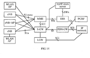
- FIG. 1 is a schematic diagram of a tightly coupled network architecture of LTE and a WLAN that can apply an embodiment of the present invention.
- An MME Mobility Management Entity, mobility management entity
- an S-GW Serving Gateway, serving gateway
- a PDN-GW Packet Data Network Gateway, packet data network gateway
- PCRF Policy charging and rules function, Policy Charging and Rules Function
- HSS Home Subscriber Server, home subscriber server
- 3GPP AAA Server shown and so on in FIG. 1 may be LTE core network EPC (Evolved Packet Core, evolved packet core) network elements defined by an existing 3GPP protocol system.
- EPC Evolved Packet Core, evolved packet core
- the MME and the S-GW are interconnected through an S11 interface, and the S-GW is connected to the PDN-GW through an S5 interface.
- the PDN-GW is connected to an external packet data network (for example, an IP network) through an SGi interface, and is meanwhile connected to the PCRF through a Gx interface.
- the MME is further connected to the HSS through an S6a interface.
- the 3GPP AAA Server is connected to the HSS through an SWx interface.
- Only one LTE wireless access network element namely an eNB (evolved Node B, evolved Node B), exists.
- the eNB is connected to the MME and the S-GW through a control plane interface S1-mme and a user plane interface S1u respectively.
- a transport layer protocol of the control plane S1-mme interface is an SCTP (Stream Control Transmission Protocol, stream control transmission protocol).
- a transport layer protocol of the user plane S1u interface is a GTP-U (GPRS Tunneling Protocol - User plane, GPRS tunneling protocol - user plane) protocol borne on a UDP. That is to say, user data is borne in a GTP-U tunnel.
- GTP-U GPRS Tunneling Protocol - User plane, GPRS tunneling protocol - user plane
- the GTP-U tunnel is uniquely identified by a combination of a TEID (Tunnel Endpoint Identifier, tunnel endpoint identifier) of a GTP-U header, a UDP port number of a UDP/IP layer, and an IP address.
- a TEID Tunnel Endpoint Identifier, tunnel endpoint identifier
- the combination that is used to identify the GTP-U tunnel and is formed of the TEID, the UDP port number of the UDP/IP layer and the IP address is called a GTP-U tunnel identifier.
- a user data offloading function may be located in the S-GW or in the eNB.
- an offloading point device may be an S-GW or an eNB. Illustration is provided below through an example in which the offloading point device is an S-GW. That is, in addition to having relevant functions defined by the existing 3GPP protocol system, the S-GW further has a function of performing offloading on a user data flow between LTE and a WLAN. That is, user plane data is transmitted through a WLAN channel and/or an LTE channel, and a control plane message is still transmitted through the LTE channel.
- a term "offloading point device” is used to refer to a network element having the user data offloading function, for example, an evolved Node B eNB or a serving gateway S-GW.
- a WLAN AP is logically connected to an S-GW.
- the WLAN AP may share a station address with an eNB, and be connected to the S-GW.
- the WLAN AP does not share a station address with an eNB, but is connected to the S-GW through the eNB.
- the WLAN AP does not share a station address with an eNB, and is directly connected to the S-GW.
- the WLAN AP share a station address with the eNB the WLAN AP and the eNB may be the same physical device, that is, the eNB is meanwhile integrated with functions of the WLAN AP, and may be two independent physical devices.
- Logical interfaces between the S-GW and the WLAN AP are divided into a control plane and a user plane.
- the control plane is used to transmit information related to management and control of the user plane to manage a user plane transmission channel between the S-GW and the WLAN AP, and may adopt a TCP over IP or SCTP over IP manner to perform transmission.
- the user plane is used to transmit a user data flow that is offloaded to the WLAN AP and transmitted through a WLAN network, and may adopt a UDP over IP manner to perform transmission.
- an AC WLAN AP Controller, WLAN AP controller
- a logical interface exists between the AC and each WLAN AP, and transmission may be performed through TCP over IP or SCTP over IP, which is mainly used to transmit WLAN related management and control information, so as to perform WLAN related management and control such as performing security authentication on a WLAN AP connected thereto, network management, and coordination and management of interference between WLAN APs.
- the AC is connected to an AAA server, so as to perform access authentication on a WLAN user.
- the AAA server is preferably a 3GPP AAA Server.
- a connection manner is the same as a connection manner between an AC or a TTG and an AAA server in the aforementioned existing WLAN network.
- FIG. 2 is a schematic diagram of a tightly coupled network architecture of LTE and a WLAN that can apply an embodiment of the present invention.
- the AC does not act as an independent device, and functions thereof and WLAN related management and control functions are integrated in the S-GW, so that the S-GW is connected to the AAA server to perform access authentication on a WLAN user.
- an offloading point device when an offloading point device is the S-GW, since the S-GW has an accounting information collecting function, the S-GW may make statistics on information on such as user data traffic passing through an LTE air interface and a WLAN air interface respectively and duration, and provide the information for an offline or online accounting system, so that the system can perform a required accounting function.
- an accounting information collecting function is required to be added to the eNB, so that the eNB may make statistics on information on such as user data traffic passing through an LTE air interface and a WLAN air interface respectively and duration, and provide the information for an offline or online accounting system, so that the system can perform a required accounting function.
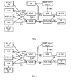
- FIG. 3A is a schematic diagram of a user data transmission flow when a WLAN AP does not share a station address with an eNB but is connected to an S-GW through the eNB, in which dashed arrows represent an IP flow transmission process.
- user data arrives at a PDN-GW through an SGi interface, arrives at an S-GW through a GTP-U tunnel, passes through an S-GW function unit, and is then divided into two parts by a user data offloading unit 310.
- the part of user data that is transmitted through an LTE air interface is sent to an eNB through a GTP-U channel, and is sent by the eNB to a UE through the LTE air interface.
- the part that is transmitted through a WLAN air interface is directly transmitted to a WLAN AP, or is forwarded to the WLAN AP through an eNB (when the WLAN AP and the eNB do not share a station address, and the WLAN AP is connected to an S-GW through the eNB), and then transmitted by a MAC layer and a physical layer of a WLAN through the WLAN air interface.
- Segmented transmission of a transport layer packet of an interface between the S-GW and the WLAN AP may adopt the following two manners. In one manner, the transport layer packet of the interface between the S-GW and the WLAN AP is directly transmitted.
- a source address and a destination address of an IP header are the S-GW and the WLAN AP respectively, which requires the eNB (the WLAN AP and the eNB do not share a station address) to have an IP layer routing function, so that user data transmitted through the WLAN AP can be correctly forwarded according to an IP address of the WLAN AP.
- the IP layer routing function may also be performed by an external IP routing device.
- both an S-GW side and an eNB side have multiplexing/demultiplexing operations, so that an S lu interface packet and a transport layer packet of the interface between the S-GW and the WLAN AP are borne on different transmission channels respectively, and then multiplexed on a physical line of an S1u interface, thereby realizing shared transmission on the S1u interface.
- a transport layer packet of the interface between the S-GW and the WLAN AP is borne on a UDP over IP tunnel of the physical line of the S1u interface, where the UDP port number is different from a UDP port number of a GTP-U channel of the S1u interface, so that multiplexing/demultiplexing operations on an eNB side can separate two paths of data that are multiplexed into each other.
- the UDP port numbers are used to distinguish different WLAN APs, that is, the eNB forwards a transport layer packet of the interface between the S-GW and the WLAN AP that is borne on a corresponding UDP port to a corresponding WLAN AP according to the UDP port number.
- the multiplexing/demultiplexing operations may be performed by an external device in addition to the S-GW and the eNB.
- a process of an uplink direction is opposite to the process of the downlink direction, and is not repeated herein.
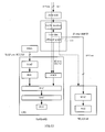
- FIG. 3B illustrates implementation of a user data offloading function in an eNB, in which dashed arrows represent an IP flow transmission process.
- Downlink user data arrives at a PDN-GW through an SGi interface, and then arrives at an eNB through an S-GW after passing through a GTP-U tunnel.
- the user data arriving at the eNB first enters a user data offloading unit 320.
- the user data offloading unit 320 divides downlink data flows of a UE into two parts, which are transmitted through LTE and WLAN air interfaces respectively.
- the part that is transmitted through the LTE air interface is completely the same as a standard LTE protocol.
- the part that is transmitted through the WLAN air interface is first transmitted to a WLAN AP (when the WLAN AP and the eNB do not share a station address) through a line between the eNB and the WLAN AP, and then transmitted by a MAC layer and a physical layer of a WLAN through the WLAN air interface.
- a process of an uplink direction is opposite to the process of the downlink direction, and is not repeated herein.
- FIG. 4 is a flow chart of a data transmission method according to an embodiment of the present invention.
- the method in FIG. 4 is executed by an offloading point device (such as an eNB and an S-GW).
- an offloading point device such as an eNB and an S-GW.
- the data offloading manner being used to designate all or a part of user data flows that are transmitted through a WLAN air interface in a downlink and/or uplink direction of the user equipment, determine a bearer channel corresponding to all or a part of the user data flows.
- the bearer channel corresponding to all or a part of user data that is transmitted through the WLAN air interface is determined, so as to transmit all or a part of the user data through the WLAN air interface in the uplink or downlink direction, thereby increasing a transmission rate.
- FIG. 5 is a flow chart of a data transmission method according to an embodiment of the present invention.
- the method in FIG. 5 is executed by a user equipment (for example, a UE or a terminal of another type), and corresponds to the method in FIG. 4 .
- a user equipment for example, a UE or a terminal of another type
- the offloading control signaling carries a cellular network identifier and a wireless local area network WLAN identifier of a user equipment, so that the offloading point device establishes a mapping relationship between the WLAN identifier of the user equipment and all bearer channels of the user equipment according to the cellular network identifier and the WLAN identifier of the user equipment.
- the offloading point device negotiates with the offloading point device to determine a data offloading manner, where the data offloading manner is used to designate all or a part of user data flows of a downlink and/or uplink direction of the user equipment that is transmitted through the WLAN air interface, so that the offloading point device determines, according to the data offloading manner and the mapping relationship, a bearer channel corresponding to all or a part of the user data flows.
- the bearer channel corresponding to all or a part of user data that is transmitted through the WLAN air interface is determined, so as to transmit all or a part of the user data through the WLAN air interface in the uplink or downlink direction, thereby increasing a transmission rate.
- an example of the cellular network identifier transmitted in 401 and 501 is an IMSI (International Mobile Subscriber Identity, international mobile subscriber identity), and an example of the WLAN identifier is a WLAN MAC (Media Access Control, media access control) address.
- IMSI International Mobile Subscriber Identity, international mobile subscriber identity
- WLAN MAC Media Access Control, media access control
- the offloading control signaling in 401 and 501 may be application layer offloading control signaling that is transmitted between a user equipment and an offloading point device through an application layer of an LTE air interface.
- the offloading control signaling may be transferred through an NAS (Non-Access-Stratum, non-access-stratum) message.
- the offloading point device is an evolved Node B eNB
- the offloading control signaling may be transferred through an RRC (Radio Resource Control, radio resource control) message.
- RRC Radio Resource Control, radio resource control
- An NAS protocol between a UE and an S-GW in existing standards may be expanded directly to add all functions performed by application layer offloading control signaling between a UE and an S-GW in the present invention, so that NAS signaling may be used to transmit offloading control related information between a UE and an S-GW in the present invention.
- an RRC protocol between a UE and an eNB in existing standards may be expanded directly, that is, RRC signaling is used for transmission.
- the offloading control signaling transmitted between the UE and the offloading point device may also be used for functions such as WLAN discovery, authentication and mobility management, which is described below in detail.
- the application layer offloading control signaling may be transmitted through an EPS (Evolved Packet System, evolved packet system) bearer.
- the EPS bearer may be one of one or more EPS bearers established by an LTE network control plane function according to a standard LTE protocol.
- a UE may be connected to multiple PDNs (Packet Data Networks, packet data networks), and a PDN connection at least includes an EPS bearer.
- An EPS bearer is a basic unit for an LTE network to perform QoS (Quality of Service) control.
- each EPS bearer corresponds to a TFT (Traffic Flow Template, traffic flow template).
- the TFT is a group of packet filters (packet filter).
- Each packet filter typically includes characteristics such as an IP address of an accessed remote server, a protocol type, and a port range, and is used to match and separate IP packets having the same characteristics. Therefore, the TFT can divide a user data flow into multiple IP flows, which are transmitted through different EPS bearers respectively.
- FIG. 6 is a schematic diagram of an EPS bearer in an LTE system.
- An uplink or downlink direction EPS bearer is formed segment by segment by a radio bearer from a UE to an eNB, an S1 bearer from the eNB to an S-GW, and an S5 bearer from the S-GW to a PDN-GW.
- the radio bearer from the UE to the eNB and the S1 bearer from the eNB to the S-GW are collectively referred to as an E-RAB (E-UTRAN Radio Access Bearer, E-UTRAN radio access bearer).
- E-RAB E-UTRAN Radio Access Bearer, E-UTRAN radio access bearer
- the S5 bearer from the S-GW to the PDN-GW and the S1 bearer from the eNB to the S-GW are both GTP-U tunnels.
- the UE adopts an uplink traffic flow template (UL-TFT) to perform matching on each packet from an application layer, so as to divide the packets into different uplink IP flows, and send the uplink IP flows through corresponding uplink EPS bearers. Therefore, the UE stores an identifier, that is, an uplink E-RAB ID, uniquely corresponding to each uplink EPS bearer of the UE.
- the S-GW also takes advantages of that the uplink E-RAB ID corresponds to an uplink EPS bearer of the UE, and meanwhile the S-GW also stores an S1 interface GTP-U tunnel identifier uniquely corresponding to the uplink E-RAB ID. Therefore, when the UE is connected to multiple PDNs at the same time, an uplink E-RAB ID can uniquely correspond to an uplink IP flow of a PDN connection.
- the PDN-GW uses a downlink TFT (DL-TFT) to perform matching on each downlink packet, so as to divide the downlink packets into different downlink IP flows, and send the downlink IP flows through corresponding downlink EPS bearers.
- DL-TFT downlink TFT
- the S-GW and the UE both take advantage of that a downlink E-RAB ID uniquely corresponds to a downlink EPS bearer of the UE, and meanwhile the S-GW also stores an S1 interface GTP-U tunnel identifier uniquely corresponding to the downlink E-RAB ID. Therefore, when the UE is connected to multiple PDNs at the same time, a downlink E-RAB ID uniquely corresponds to a downlink IP flow of a PDN connection.
- EPS bearers are formed of a default bearer and a dedicated bearer.
- the default bearer is established during network attachment (Network Attachment), and the dedicated bearer is a bearer added based on the default bearer. If the UE does not have a pre-allocated static IP address, the UE may request the network to allocate an IP address during network attachment. Different EPS bearers of a same PDN connection have a same IP address.
- the UE enters an EMM-REGISTERED state, the EPS bearer is in an active state, the GTP-U tunnels of the S1 interface and the S5 interface are open, and a user data packet may be transmitted between the eNB and the PDN-GW.
- a control plane function of an LTE network may establish one or more EPS bearers of a user plane according to a standard LTE protocol.
- the eNB maps a radio bearer of each EPS bearer into an LTE radio link, or a WLAN radio link, or LTE and WLAN radio links provided at the same time.
- the UE maps a radio bearer of each EPS bearer into an LTE radio link, or a WLAN radio link, or LTE and WLAN radio links provided at the same time.
- Control plane messages (including NAS and AS messages) are still transmitted through the LTE air interface, but a data plane may be partially or completely transmitted through the WLAN air interface.
- the EPS bearer is expanded, so as to allow the radio bearer part of the EPS bearer to be an LTE radio link, or a WLAN radio link, or LTE and WLAN radio links provided at the same time.
- the following EPS bearers are all EPS bearers expanded in the present invention, and are not limited to the definition in the existing LTE protocol that the radio bearer part of the EPS bearer is only an LTE radio link.
- the user data offloading function can be located not only in the S-GW but also in the eNB.
- illustration is provided below by taking an example in which the user data offloading function is located in the S-GW.
- LTE and WLAN converged transmission related functions, there is no difference between locating the user data offloading function in the S-GW and locating the user data offloading function in the eNB, so that the following description of performing offloading on user data between the LTE and the WLAN is applicable to both the situation in which the user data offloading function is located in the S-GW and the situation in which the user data offloading function is located in the eNB.
- the UE may negotiate with the offloading point device (for example, an eNB or an S-GW) through the application layer offloading control signaling.
- the offloading point device for example, an eNB or an S-GW
- a data offloading method of the present invention is described below with reference to specific embodiments.
- the determining the bearer channel corresponding to all or a part of the user data flows includes: according to the determined data offloading manner, establishing an end-to-end tunnel, running through a wireless local area network WLAN air interface, to the user equipment, the end-to-end tunnel being used to transmit all or a part of the user data flows, and establishing a mapping relationship between a tunnel number of the end-to-end tunnel and an E-RAB ID corresponding to the bearer channel (for example, a GTP-U tunnel shown in FIG. 6 ).
- the offloading point device may transmit the user data flow to the user equipment through the end-to-end tunnel.
- the offloading point device can also determine a bearer channel through which the uplink user data flow is forwarded.
- an existing IP flow bearing mechanism of LTE is applied, that is, in the downlink direction, the PDN-GW uses an existing DL-TFT function to divide downlink user data of the UE into different downlink IP flows (IP Flow).
- IP Flow downlink IP flows
- the downlink IP flow in a core network arrives at the S-GW through a corresponding downlink GTP-U tunnel (an example of the bearer channel).
- the S-GW connects a part or all of the downlink GTP-U tunnels that bear the downlink IP flows to corresponding downlink WLAN radio bearers, and connects the rest of the downlink GTP-U tunnels that bear the downlink IP flows to corresponding downlink LTE radio bearers, so that a part or all of the downlink IP flows are offloaded to the WLAN air interface, thereby realizing offloading and converged transmission of downlink user data at the LTE and WLAN air interfaces.
- the UE uses an existing UL-TFT function to divide uplink user data of the UE into different uplink IP flows.
- the S-GW connects a part or all of the uplink GTP-U tunnels that bear the uplink IP flows to corresponding uplink WLAN radio bearers, and connects the rest of the uplink GTP-U tunnels that bear the uplink IP flows to corresponding uplink LTE radio bearers, so that as long as the UE sends a part or all of the uplink IP flows through corresponding uplink WLAN radio bearers, and sends the rest of the uplink IP flows through corresponding uplink LTE radio bearer, the S-GW can forward a part or all of the uplink IP flows that are borne by the uplink WLAN radio to corresponding uplink GTP-U tunnels, and forward the rest of the uplink IP flows that are borne by the uplink LTE radio to corresponding uplink GTP-U tunnels, thereby realizing offloading and converged transmission of uplink user data at the LTE and WLAN air
- the S-GW is required to perform the operation of connecting a part or all of the GTP-U tunnels of the UE to the WLAN radio bearers of the UE for the UE, which includes: in the uplink direction, connecting a part or all of the GTP-U tunnels that bearer the uplink IP flows to the corresponding uplink WLAN radio bearers and connecting the rest of the GTP-U tunnels that bear the uplink IP flows to the corresponding uplink WLAN radio bearers; and in the downlink direction, connecting a part or all of the GTP-U tunnels that bear the downlink IP flows to the corresponding downlink WLAN radio bearers and connecting the rest of the GTP-U tunnels that bear the downlink IP flows to the corresponding downlink WLAN radio bearers.
- the WLAN AP uses a MAC address of a UE to uniquely identify the UE, and a user plane interface between the S-GW and the WLAN AP may use UDP port numbers to distinguish different UEs. Therefore, the WLAN AP and the S-GW may establish a mapping relationship between the MAC address of the UE and a corresponding UDP port number of the user plane interface between the S-GW and the WLAN AP. In this way, any uplink data packet from the UE of the MAC address is received by the WLAN AP and sent through a corresponding UDP port to the S-GW.
- the S-GW uses the UDP port number to make the uplink data packet correspond to a corresponding bearer channel (for example, a GTP-U tunnel) of the UE.
- a bearer channel for example, a GTP-U tunnel
- the S-GW sends a downlink data packet, which is required to be transmitted through the WLAN air interface, of the UE to the WLAN AP through the UDP port according to the mapping relationship between the UDP port number of the user plane interface between the S-GW and the WLAN AP and the MAC address of the UE.
- the WLAN AP receives a downlink data packet that is transmitted through a certain UDP port and from the S-GW, and searches for the MAC address of the corresponding UE according to the UDP port number, so as to send the downlink data packet to the UE of the corresponding MAC address through the WLAN air interface.
- the S-GW can only obtain the UDP port number or information of a WLAN MAC address of the UE from the interface of the S-GW and the WLAN AP.
- the S-GW is required to establish a mapping relationship between the WLAN MAC address of the UE and all bearer channels of the UE.
- the UE informs the S-GW of the mapping relationship between the IMSI of the UE and the WLAN MAC address of the UE through application layer offloading control signaling between the UE and the S-GW, where the IMSI is a unique identifier of a UE in a mobile cellular network.
- the S-GW stores the mapping relationship between the IMSI of each UE and all bearer channels of the UE. In this way, by using the IMSI and the WLAN MAC address of the UE, the S-GW may establish a mapping relationship between the WLAN MAC address of the UE and all the bearer channels of the UE.
- the WLAN air interface does not distinguish a part or all of IP flows of the UE that are transmitted through the WLAN air interface, so that in order to enable the UE to distinguish in the downlink direction different IP flows of the UE that are transmitted through the WLAN air interface, and to enable the S-GW to distinguish in the uplink direction different IP flows of the UE and send all the IP flows to corresponding GTP-U tunnels, the S-GW and the UE are further required to establish a consistent mapping relationship between a part or all of the IP flows that are transmitted through the WLAN air interface and the corresponding bearers. Therefore, in this embodiment, the UE and the S-GW establish multiple end-to-end tunnels. An end-to-end tunnel transmits an IP flow of the UE that is transmitted through the WLAN air interface. Therefore, according to tunnel numbers of the end-to-end tunnels between the UE and the S-GW, the S-GW and the UE can determine the mapping relationship between a part or all of the IP flows that are transmitted through the WLAN air interface and the corresponding bearers.
- the UE and the S-GW each store an EPS bearer identifier of each UE, that is, an E-RAB ID, which corresponds to a corresponding EPS bearer. That is to say, as long as the UE and the S-GW succeed in negotiating, through the application layer offloading control signaling between the UE and the S-GW, the mapping relationship between the tunnel number of the end-to-end tunnel between the UE and the S-GW, which transmit a part or all of the IP flows through the WLAN air interface, and the E-RAB ID of the corresponding bearer, the S-GW and the UE may determine, according to the mapping relationship, the mapping relationship between a part or all of the IP flows that are transmitted through the WLAN air interface and the corresponding bearer.
- the S-GW may distinguish different PDN connections of a same UE and uplink IP flows on different EPS bearers of a same PDN connection according to the tunnel numbers, so as to send the uplink IP flow to the PDN-GW through the GTP-U tunnel of the corresponding S5 interface; in the downlink direction, the S-GW sends downlink IP flows of the UE from different GTP-U tunnels to the UE through corresponding end-to-end tunnels between the UE and the S-GW and through the WLAN air interface, so that the UE can distinguish different PDN connections of the UE according to the tunnel numbers of the end-to-end tunnels between the UE and the S-GW.
- FIG. 7A illustrates an end-to-end tunnel manner between an UE and an S-GW.
- a user IP packet (an inner IP packet) is encapsulated in an outer UDP/IP packet.
- a source address of an IP packet header of a user IP packet is an IP address of the UE
- a destination address is an IP address of a remote server
- a source address of an IP packet header of an outer IP packet is the IP address of the UE
- a destination address is an IP address of an eNB or an S-GW corresponding to the UE
- a UDP port number of a UDP header of the outer IP packet is a tunnel number of the end-to-end tunnel.
- FIG. 7B illustrates an end-to-end tunnel manner between an UE and an S-GW. It can be seen that, before a user IP packet, a tunnel layer field is added, which is used to indicate an E-RAB ID of a bearer corresponding to the end-to-end tunnel, and acts as a tunnel number of the end-to-end tunnel.
- the end-to-end tunnel between the UE and the S-GW may also be achieved through other manners, for example, achieved by adopting protocols such as IPSec (Internet Protocol Security, Internet protocol security) and IEEE 802.2 LLC (Logical Link Control, logical link control).
- protocols such as IPSec (Internet Protocol Security, Internet protocol security) and IEEE 802.2 LLC (Logical Link Control, logical link control).
- FIG. 8 is a schematic diagram of protocol stacks, which are involved in this embodiment, of a UE, a WLAN AP, and an S-GW.
- one part of user data flows (“user data A” shown in the drawing) are transmitted through an LTE air interface
- the other part of the user data flows (“user data B” shown in the drawing) are transmitted through a WLAN air interface
- this part of the user data flows are transmitted through an end-to-end tunnel between the UE and the S-GW.
- a data plane interface between the S-GW and the WLAN AP adopts a UDP over IP manner for transmission
- a control plane interface adopts a TCP over IP or SCTP over IP manner for transmission
- all of the data flows ("user data A+B" shown in the drawing) of the user is finally transmitted between the S-GW and the PDN-GW through a GTP-U tunnel of an S1 interface user plane.
- the LTE air interface is further used to transmit application layer offloading control signaling between the UE and the S-GW, and the signaling may be transmitted through a TCP protocol.
- a first manner in which the UE and the S-GW identify the application layer offloading control signaling is: when multiple EPS bearers exist between the UE and the S-GW, a system allocates a specific bearer channel (for example, one of the multiple EPS bearers) to the application layer offloading control signaling, so that any information transmitted on the specific bearer can be processed by the UE and the S-GW as application layer offloading control signaling.
- a second manner in which the UE and the S-GW identify the application layer offloading control signaling is: a UE side address of the application layer offloading control signaling, namely, an IP address obtained by the UE during network attachment, an S-GW side IP address, and a specific IP address (the UE may obtain an IP address of a serving S-GW thereof through a DNS in a domain name manner) configured by a system are transmitted, so that when receiving an IP packet with a destination address being the specific IP address, the S-GW determines that the IP packet bears application layer offloading control signaling from the UE; similarly, when receiving an IP packet with a source address being the specific IP address, the UE determines that the IP packets bears application layer offloading control signaling from the S-GW.
- the specific IP address is located in the IP address space of the external PDN. To avoid confusing the application layer offloading control signaling and the data packet of the UE, the specific IP address may be a reserved IP address. Taking IPv4 as an example, the specific IP address may be an address between 192.168.0.0 and 192.168.255.255.
- a third manner in which the UE and the S-GW identify the application layer offloading control signaling is: a UE side address of the application layer offloading control signaling, namely, an IP address obtained by the UE during network attachment, an S-GW side IP address, and a specific IP address (the UE may obtain an IP address of a serving S-GW thereof through a DNS in a domain name manner) configured by a system are transmitted, and a TCP protocol that transmits the application layer offloading control signaling adopts a specific TCP port, so that when a destination address received by the S-GW is the specific IP address and a TCP port number is the specific TCP port, it is determined that the TCP over IP packet bears application layer offloading control signaling from the UE; similarly, when a source address received by the UE is the specific IP address and a TCP port number is the specific TCP port, it is determined that the TCP over IP packet bears application layer offloading control signaling from the S-GW.
- the specific IP address is located in the IP address space of the external PDN. To avoid confusing the application layer offloading control signaling and the data packet of the UE, the specific IP address may be a reserved IP address. Taking IPv4 as an example, the specific IP address may be an address between 192.168.0.0 and 192.168.255.255.
- the specific TCP port is a less frequently used TCP port (for example, 0-1024 are frequently used TCP port numbers).
- An establishment process of converged transmission of the LTE and the WLAN in this embodiment is described below.
- a network attachment process is started to enter an EMM-REGISTERED state, and at the moment, an EPS bearer is in an active state, and the UE therefore obtains an IP address and establishes at least one EPS bearer.
- the UE and the S-GW may use one of the at least one EPS bearer to initiate an application layer offloading control signaling process between the UE and the S-GW, so as to establish the converged transmission of the LTE and the WLAN.
- the S-GW can obtain location information of the UE.
- the S-GW can obtain a cell or a tracking area (Tracking Area, TA) where the UE is.
- the eNB may further obtain, through wireless measurement on the LTE air interface, more precise location information on whether the UE is located in the center of the cell or on edges of some neighboring cells.
- the S-GW may notify, through application layer offloading control signaling, the UE that an accessible WLAN AP exists in a current location, so as to enable the WLAN function module to start WLAN offloading.
- the S-GW may also notify, through application layer offloading control signaling, the UE that no accessible WLAN AP exists in a current location (for example, the UE leaves a WLAN hot spot area, or the WLAN limits access of users due to reasons such as severe interference and a too heavy load), so as to disable the WLAN function module to reduce power consumption of the UE.
- the UE may obtain a BSSID (Basic Service Set Identity, basic service set identity) uniquely identifying the WLAN AP.
- BSSID Basic Service Set Identity
- the BSSID of a WLAN AP is a WLAN MAC address of the WLAN AP.
- the S-GW stores a BSSID list of all WLAN APs connected to the S-GW.
- the UE may send, through application layer offloading control signaling between the UE and the S-GW, a WLAN MAC address thereof and a BSSID of a WLAN AP with which the UE attempts to be associated to the S-GW, and the S-GW matches the BSSID with a BSSID list stored by the S-GW and being of the connected WLAN APs, and if the matching fails, notifies the UE of not initiating association to the WLAN AP, and if the matching succeeds, notifies the UE that association with the WLAN AP and a WLAN authentication process may be initiated.
- the WLAN authentication process may adopt an authentication manner based on a SIM (Subscriber Identity Module, subscriber identity module) or a USIM (Universal Subscriber Identity Module, universal subscriber identity module).
- SIM Subscriber Identity Module
- USIM Universal Subscriber Identity Module, universal subscriber identity module
- Standards such as specifications RFC4186 and RFC4187 of IETF may be referred to for a detailed process.
- the WLAN authentication process may also adopt an automatic authentication manner based on a WLAN MAC address or a WLAN MAC address and an IP address of the UE.
- the UE informs the S-GW of a WLAN MAC address thereof or even an IP address thereof through application layer offloading control signaling between the UE and the S-GW
- the S-GW sends the WLAN MAC address of the UE or even the IP address thereof to the WLAN AP that is successfully matched through the BSSID and is associated.
- the UE further negotiates an encryption algorithm and a key to the encryption algorithm with the S-GW through application layer offloading control signaling between the UE and the S-GW.
- the S-GW sends the negotiated encryption algorithm of the WLAN air interface and the key to the encryption algorithm to the WLAN AP that is successfully matched through the BSSID and is associated.
- the WLAN AP establishes a binding relationship between the WLAN MAC address of the UE and the key to the encryption algorithm, or a binding relationship between the WLAN MAC address and IP address of the UE and the key to the encryption algorithm. In this way, only a UE satisfying the binding relationship can be considered legal by the WLAN AP and permitted for accessing.
- the UE informs the S-GW through application layer offloading control signaling between the UE and the S-GW that the UE (a WLAN MAC address is used to identify the UE) already accesses the WLAN AP, or the WLAN AP informs the S-GW through a control plane interface between the WLAN AP and the S-GW that the UE already accesses the WLAN AP, and the S-GW stores a mapping relationship between the UE and a BSSID of the WLAN AP to which the UE accesses.
- the S-GW updates the mapping relationship between the UE and a BSSID of a new WLAN AP to which the UE accesses. In this way, by using the mapping relationship, the S-GW can always send downlink user data offloaded to the WLAN to a WLAN AP currently accessed by the UE, so as to send the downlink user data to the UE through the WLAN AP.
- the UE and the S-GW make the following preparations for establishment of converged transmission of the LTE and the WLAN.
- the UE informs the S-GW of the IMSI and the WLAN MAC address of the UE through the application layer offloading control signaling between the UE and the S-GW, the S-GW uses the IMSI and the WLAN MAC address of the UE to establish a mapping relationship between the WLAN MAC address of the UE and all bearer channels (that is, GTP-U tunnels) of the UE.
- the UE may further negotiate and determine a data offloading manner of the UE through the application layer offloading control signaling between the UE and the S-GW, for example, for uplink and downlink respectively, determine which IP flows (one-to-one corresponding to E-RAB IDs/GTP-U tunnel identifiers respectively) are transmitted through the WLAN air interface (the rest is transmitted through the LTE air interface). For example, it is assumed that a PDN connection of a UE establishes four EPS bearers, which correspond to four IP flows respectively. After negotiation, the first and fourth IP flows are transmitted through the WLAN air interface, and the second and third IP flows are transmitted through the LTE air interface.
- a user is allowed to configure a ratio or priority of data traffic transmitted through the LTE air interface and the WLAN air interface. For example, if a tariff policy of an operator stipulates that WLAN access is free, or the tariff of the traffic passing through the WLAN is lower than the tariff of LTE, the user is more willing to preferably select the WLAN for data transmission. For another example, when power of a battery of the user is insufficient, the user is more inclined to select the air interface that consumes less power to transmit data, so as to extend the battery life of a terminal.
- the system performs further selection according certain principles based on the selection of the user. For example, the system may perform selection according to congestion situations of the two air interfaces. When a transmission rate of the WLAN decreases significantly due to strong interference, the system may, based on the selection of the user, offload the traffic to the LTE air interface.
- the UE may further negotiate, through the application layer offloading control signaling between the UE and the S-GW, the mapping relationship between the tunnel number of the end-to-end tunnel between the UE and the S-GW, which transmit a part or all of the IP flows through the WLAN air interface, and the E-RAB ID of the corresponding bearer.
- the S-GW and the UE may determine the mapping relationship between a part or all of the IP flows that are transmitted through the WLAN air interface and the corresponding bearer.
- the S-GW and the WLAN AP accessed by the UE negotiate, through a control plane interface between the S-GW and the WLAN AP, a UDP port number of uplink data and/or downlink data of the UE transmitted by the user plane interface between the S-GW and the WLAN AP.
- the WLAN AP and the S-GW may establish a mapping relationship between the MAC address of the UE and a corresponding UDP port number of the user plane interface between the S-GW and the WLAN AP.
- the UE uses the UL-TFT function to divide the uplink data flows of the UE into different uplink IP flows, maps a part or all of uplink IP flows that are required to be transmitted through the WLAN air interface to a corresponding end-to-end tunnel between the UE and the S-GW, which are sent to the WLAN AP through the WLAN air interface.
- the WLAN AP sends all uplink data packets of the UE from the MAC address to the S-GW through a corresponding UDP port.
- the S-GW uses the UDP port number to find a corresponding bearer channel (for example, a GTP-U tunnel) of the UE according to the mapping relationship between the UDP port number of the user plane interface between the S-GW and the WLAN AP and the MAC address of the UE, and uses the mapping relationship between the end-to-end tunnel number between the UE and the S-GW and the corresponding GTP-U tunnel of a part or all of the IP flows to forward a part or all of the IP flows to corresponding uplink GTP-U tunnels respectively.
- a corresponding bearer channel for example, a GTP-U tunnel
- the UE sends the rest of the uplink IP flows to the S-GW through a corresponding uplink LTE radio bearer according to existing standards of the LTE, which are then forwarded by the S-GW to corresponding uplink GTP-U tunnels respectively.
- a corresponding uplink LTE radio bearer according to existing standards of the LTE, which are then forwarded by the S-GW to corresponding uplink GTP-U tunnels respectively.
- the PDN-GW uses the DL-TFT function to divide the downlink data flows of the UE into different downlink IP flows.
- the downlink IP flows arrive at the S-GW through corresponding downlink GTP-U tunnels.
- the S-GW maps a part or all of the downlink IP flows to corresponding end-to-end tunnels between the UE and the S-GW respectively, which are sent to the WLAN AP through a corresponding UDP port.
- the WLAN AP uses the UDP port number to send all downlink data packets of the UE from the UDP port to the UE of the MAC address through the WLAN air interface according to the mapping relationship between the UDP port number of the user plane interface between the S-GW and the WLAN AP and the MAC address of the UE.
- the UE uses the mapping relationship between the end-to-end tunnel number between the UE and the S-GW and a part or all of the IP flows to distinguish IP flows of different PDN connections of the UE. Meanwhile, the S-GW sends the rest of the downlink IP flows to the UE through a corresponding downlink LTE radio bearer according to existing standards of the LTE. In this way, converged transmission of the downlink user data at the LTE and WLAN air interfaces is realized.
- the S-GW receives an S-GW handover request of the UE.
- the S-GW Before the S-GW decides to start S-GW handover, the S-GW first performs reconfiguration on offloading to reconfigure a user data flow originally offloaded by the WLAN to be transmitted by the LTE, and notifies, through the application layer offloading control signaling between the UE and the S-GW, the UE and a currently accessed WLAN AP to dissociate, or informs, through the control plane interface between the S-GW and the WLAN AP, the UE that the currently accessed WLAN AP dissociates the UE.
- the S-GW After the dissociation succeeds, the S-GW starts an S-GW handover process. After the S-GW handover completes and the UE is handed over to a new S-GW, if an accessible WLAN AP is currently available, the UE follows the aforementioned process again to access a WLAN AP connected to a current serving S-GW, so as to re-establish converged transmission of the LTE and the WLAN.
- Embodiment 2 (An S-GW has a built-in packet filter/a UE has a built-in packet filter outside an LTE communication module)
- a PDN connection of a UE corresponds to only one EPS bearer, that is, only one GTP-U tunnel exists between a PDN-GW and an S-GW.
- a DL-TFT function of the PDN-GW is not used to divide downlink data flows of the UE.
- a packet filter is built in an S-GW, to divide downlink user data of each PDN connection of the UE into different downlink IP flows (IP Flow).
- the S-GW then sends a part or all of the downlink IP flows to a WLAN AP according to a data offloading manner negotiated with the UE, which are transmitted to the UE through a WLAN air interface, and meanwhile the rest of the downlink IP flows are transmitted to the UE through an LTE air interface, thereby realizing offloading and converged transmission of the downlink user data at the LTE and WLAN air interfaces.
- the UE uses a built-in packet filter outside an LTE communication module (generally an independent ASIC chip) to divide an uplink data flow from each PDN connection of an application layer into different uplink IP flows.
- the UE then sends a part or all of the uplink IP flows to a WLAN AP through the WLAN air interface according to a data offloading manner negotiated with the S-GW, which are then transmitted by the WLAN AP to the S-GW. Meanwhile, the rest of the uplink IP flows are transmitted to the S-GW through the LTE air interface.
- the S-GW forwards all the uplink IP flows of the PDN connection from the WLAN air interface and the LTE air interface to an uplink GTP-U tunnel corresponding to the PDN connection, thereby realizing offloading and converged transmission of the uplink user data at the LTE and WLAN air interfaces.
- a WLAN AP uses a MAC address of a UE to uniquely identify the UE, and a user plane interface between the S-GW and the WLAN AP may use UDP port numbers to distinguish different UEs. Therefore, the WLAN AP and the S-GW may establish a mapping relationship between the MAC address of the UE and a corresponding UDP port number of the user plane interface between the S-GW and the WLAN AP. In this way, any uplink data packet from the UE of the MAC address is received by the WLAN AP and sent through a corresponding UDP port to the S-GW.
- the S-GW uses the UDP port number to make the uplink data packet correspond to a corresponding bearer channel (for example, a GTP-U tunnel) of the UE.
- a bearer channel for example, a GTP-U tunnel
- the S-GW sends a downlink data packet, which is required to be transmitted through the WLAN air interface, of the UE to the WLAN AP through the UDP port according to the mapping relationship between the UDP port number of the user plane interface between the S-GW and the WLAN AP and the MAC address of the UE.
- the WLAN AP receives a downlink data packet that is transmitted through a certain UDP port and from the S-GW, and searches for the MAC address of the corresponding UE according to the UDP port number, so as to send the downlink data packet to the UE of the corresponding MAC address through the WLAN air interface.
- the S-GW can only obtain the UDP port number or information of a WLAN MAC address of the UE from the interface of the S-GW and the WLAN AP.
- the S-GW is required to establish a mapping relationship between the WLAN MAC address of the UE and all bearer channels of the UE.
- a PDN connection of a UE corresponds to only one EPS bearer, that is, only one GTP-U tunnel exists between the PDN-GW and the S-GW, because the UE may be connected to multiple PDNs at the same time, a UE in the S-GW may correspond to multiple GTP-U tunnels.
- the UE informs the S-GW of a mapping relationship between the IMSI of the UE and the WLAN MAC address of the UE through application layer offloading control signaling between the UE and the S-GW, where the IMSI is a unique identifier of a UE in a mobile cellular network.
- the S-GW stores a mapping relationship between the IMSI of each UE and all bearer channels of the UE. In this way, by using the IMSI and the WLAN MAC address of the UE, the S-GW may establish a mapping relationship between the WLAN MAC address of the UE and all the bearer channels of the UE.
- a PDN connection of a UE establishes only one EPS bearer, that is, only one GTP-U tunnel exists between the PDN-GW and the S-GW, because the UE may be connected to multiple PDNs at the same time, a UE in the S-GW may correspond to multiple GTP-U tunnels.
- different PDN connections of a same UE are also required to be distinguished, so as to provide uplink data of a corresponding PDN connection for a corresponding application layer.
- the WLAN AP cannot distinguish IP flows of different PDN connections of the same UE that are transmitted from the UE through the WLAN air interface, so that both the S-GW and the UE are required to be provided with a method for distinguishing the IP flows of the different PDN connections of the same UE that are transmitted from the UE through the WLAN air interface.
- the IP address is used to distinguish the IP flows over one PDN connection from the IP flows over another PDN connection of the same UE.
- the IP addresses in different PDNs are independent of each other. Therefore, when a UE is connected to multiple PDNs simultaneously, it is possible that the IP addresses allocated to the same UE for use in different PDN connections are the same. Therefore, the IP address allocated for use in different PDN connections should not be the same so that the IP address can be used to distinguish between different PDN connections of the same UE.
- the IP address space is enormous, it is hardly possible that two or more PDNs allocate the same IP address to the same UE; if the IP address allocated for the second PDN connection is the same as the IP address allocated for the first PDN connection, the UE may require the network to allocate another IP address for the second PDN connection to avoid such special circumstances.
- the UE resolves a destination address of a user IP packet on each downlink EPS bearer of the UE (that is, an IP address of a corresponding PDN connection of the UE), so as to establish a mapping relationship between IP addresses of all PDN connections of the UE and corresponding application layers.
- the S-GW resolves a source address of a user IP packet on each uplink EPS bearer of the UE (that is, an IP address of a corresponding PDN connection of the UE), so as to establish a mapping relationship between IP addresses of all PDN connections of the UE and corresponding GTP-U tunnels.
- application layer offloading control signaling between the UE and the S-GW can be used to transmit a part or all of uplink and/or downlink IP flows through the WLAN air interface, so as to establish converged transmission of the LTE and the WLAN.
- FIG. 9 is a schematic diagram of protocol stacks, which are involved in this embodiment, of a UE, a WLAN AP, and an S-GW.
- one part of user data flows (“user data A” shown in the drawing) are transmitted through an LTE air interface
- the other part of the user data flows (“user data B” shown in the drawing) are transmitted through a WLAN air interface.
- a data plane interface between the S-GW and the WLAN AP adopts a UDP over IP manner for transmission
- a control plane interface adopts a TCP over IP or SCTP over IP manner for transmission
- all of the data (“user data A+B" shown in the drawing) of the user is finally transmitted between the S-GW and the PDN-GW through a GTP-U tunnel of an S1 interface user plane.
- the LTE air interface is further used to transmit application layer offloading control signaling between the UE and the S-GW, and the signaling may be transmitted through a TCP protocol.
- a first manner in which the UE and the S-GW identify the application layer offloading control signaling is: a UE side address of the application layer offloading control signaling, namely, an IP address obtained by the UE during network attachment, an S-GW side IP address, and a specific IP address (the UE may obtain an IP address of a serving S-GW thereof through a DNS in a domain name manner) configured by a system are transmitted, so that when receiving an IP packet with a destination address being the specific IP address, the S-GW determines that the IP packet bears application layer offloading control signaling from the UE; similarly, when receiving an IP packet with a source address being the specific IP address, the UE determines that the IP packets bears application layer offloading control signaling from the S-GW.
- the specific IP address is located in the IP address space of the external PDN. To avoid confusing the application layer offloading control signaling and the data packet of the UE, the specific IP address may be a reserved IP address. Taking IPv4 as an example, the specific IP address may be an address between 192.168.0.0 and 192.168.255.255.
- a second manner in which the UE and the S-GW identify the application layer offloading control signaling is: a UE side address of the application layer offloading control signaling, namely, an IP address obtained by the UE during network attachment, an S-GW side IP address, and a specific IP address (the UE may obtain an IP address of a serving S-GW thereof through a DNS in a domain name manner) configured by a system are transmitted, and a TCP protocol that transmits the application layer offloading control signaling adopts a specific TCP port, so that when a destination address received by the S-GW is the specific IP address and a TCP port number is the specific TCP port, it is determined that the TCP over IP packet bears application layer offloading control signaling from the UE; similarly, when a source address received by the UE is the specific IP address and a TCP port number is the specific TCP port, it is determined that the TCP over IP packet bears application layer offloading control signaling from the S-GW.
- the specific IP address is located in the IP address space of the external PDN. To avoid confusing the application layer offloading control signaling and the data packet of the UE, the specific IP address may be a reserved IP address. Taking IPv4 as an example, the specific IP address may be an address between 192.168.0.0 and 192.168.255.255.
- the specific TCP port is a less frequently used TCP port (for example, 0-1024 are frequently used TCP port numbers).
- An establishment process of converged transmission of the LTE and the WLAN is described below.
- a network attachment process is started to enter an EMM-REGISTERED state, and at the moment, an EPS bearer is in an active state, and the UE therefore obtains an IP address of a corresponding PDN connection and establishes an EPS bearer.
- the UE and the S-GW may use the EPS bearer to initiate an application layer offloading control signaling process between the UE and the S-GW, so as to establish the converged transmission of the LTE and the WLAN.
- the S-GW can obtain location information of the UE.
- the S-GW can obtain a cell or a tracking area (Tracking Area, TA) where the UE is.
- the eNB may further obtain, through wireless measurement on the LTE air interface, more precise location information on whether the UE is located in the center of the cell or on edges of some neighboring cells.
- the S-GW may notify, through application layer offloading control signaling, the UE that an accessible WLAN AP exists in a current location, so as to enable the WLAN function module to start WLAN offloading.
- the S-GW may also notify, through application layer offloading control signaling, the UE that no accessible WLAN AP exists in a current location (for example, the UE leaves a WLAN hot spot area, or the WLAN limits access of users due to reasons such as severe interference and a too heavy load), so as to disable the WLAN function module to reduce power consumption of the UE.
- the UE may obtain a BSSID uniquely identifying the WLAN AP.
- the BSSID of a WLAN AP is a WLAN MAC address of the WLAN AP.
- the S-GW stores a BSSID list of all WLAN APs connected to the S-GW.
- the UE may send, through application layer offloading control signaling between the UE and the S-GW, a WLAN MAC address thereof and a BSSID of a WLAN AP with which the UE attempts to be associated to the S-GW, and the S-GW matches the BSSID with a BSSID list stored by the S-GW and being of the connected WLAN APs, and if the matching fails, notifies the UE of not initiating association to the WLAN AP, and if the matching succeeds, notifies the UE that association with the WLAN AP and a WLAN authentication process may be initiated.
- the WLAN authentication process may adopt an authentication manner based on a SIM or a USIM.
- Standards such as specifications RFC4186 and RFC4187 of IETF may be referred to for a detailed process.
- the WLAN authentication process may also adopt an automatic authentication manner based on a WLAN MAC address or a WLAN MAC address and an IP address of the UE.
- the UE informs the S-GW of a WLAN MAC address thereof or even an IP address thereof through application layer offloading control signaling between the UE and the S-GW.
- the S-GW sends the WLAN MAC address of the UE or even the IP address thereof to the WLAN AP that is successfully matched through the BSSID and is associated.
- the UE further negotiates an encryption algorithm and a key to the encryption algorithm with the S-GW through application layer offloading control signaling between the UE and the S-GW.
- the S-GW sends the negotiated encryption algorithm of the WLAN air interface and the key to the encryption algorithm to the WLAN AP that is successfully matched through the BSSID and is associated.
- the WLAN AP establishes a binding relationship between the WLAN MAC address of the UE and the key to the encryption algorithm, or a binding relationship between the WLAN MAC address and IP address of the UE and the key to the encryption algorithm. In this way, only a UE satisfying the binding relationship can be considered legal by the WLAN AP and permitted for accessing.
- the UE informs the S-GW through application layer offloading control signaling between the UE and the S-GW that the UE (a WLAN MAC address is used to identify the UE) already accesses the WLAN AP, or the WLAN AP informs the S-GW through a control plane interface between the WLAN AP and the S-GW that the UE already accesses the WLAN AP, and the S-GW stores a mapping relationship between the UE and a BSSID of the WLAN AP to which the UE accesses.
- the S-GW updates the mapping relationship between the UE and a BSSID of a new WLAN AP to which the UE accesses. In this way, by using the mapping relationship, the S-GW can always send downlink user data offloaded to the WLAN to a WLAN AP currently accessed by the UE, so as to send the downlink user data to the UE through the WLAN AP.
- the UE and the S-GW make the following preparations for establishment of converged transmission of the LTE and the WLAN.
- the S-GW and the WLAN AP accessed by the UE negotiate, through a control plane interface between the S-GW and the WLAN AP, a UDP port number of uplink data and/or downlink data of the UE transmitted by the user plane interface between the S-GW and the WLAN AP.
- the WLAN AP and the S-GW may establish a mapping relationship between the MAC address of the UE and a corresponding UDP port number of the user plane interface between the S-GW and the WLAN AP.
- the UE uses a built-in packet filter outside an LTE communication module (generally an independent ASIC chip) to divide an uplink data flow from each PDN connection of an application layer into different uplink IP flows.
- the UE then sends a part or all of the uplink IP flows to a WLAN AP through the WLAN air interface according to a data offloading manner negotiated with the S-GW, and the WLAN AP transmits all uplink data packets of the UE from the MAC address to the S-GW through a corresponding UDP port.
- the S-GW uses the UDP port number to find a corresponding bearer channel (for example, a GTP-U tunnel) of the UE according to the mapping relationship between the UDP port number of the user plane interface between the S-GW and the WLAN AP and the MAC address of the UE, divides all uplink data packets of the UE that are transmitted through the WLAN into at least one data flow according different source IP addresses (corresponding to different PDN connections), and uses the established mapping relationship between the IP addresses of all the PDN connections of the UE and the corresponding GTP-U tunnels to forward the at least one data flow to the corresponding GTP-U tunnel respectively.
- a corresponding bearer channel for example, a GTP-U tunnel
- the UE sends the rest of the uplink IP flows to the S-GW through a corresponding uplink LTE radio bearer according to existing standards of the LTE, which are then forwarded by the S-GW to corresponding uplink GTP-U tunnels respectively.
- a corresponding uplink LTE radio bearer according to existing standards of the LTE, which are then forwarded by the S-GW to corresponding uplink GTP-U tunnels respectively.
- the S-GW divides a downlink data flow of each PDN connection of the UE into different downlink IP flows through a built-in packet filter.
- the S-GW then sends a part or all of the downlink IP flows to a WLAN AP through a corresponding UDP port according to a data offloading manner negotiated with the UE.
- the WLAN AP uses the UDP port number to send all downlink data packets of the UE from the UDP port to the UE of the MAC address through the WLAN air interface according to the mapping relationship between the UDP port number of the user plane interface between the S-GW and the WLAN AP and the MAC address of the UE.
- the UE divides all uplink data packets from the WLAN air interface into at least one data flow according different destination IP addresses (corresponding to different PDN connections), and uses the established mapping relationship between the IP addresses of all the PDN connections of the UE and the corresponding application layers to forward the at least one data flow to the corresponding application layer respectively.
- the S-GW sends the rest of the downlink IP flows to the UE through a corresponding downlink LTE radio bearer according to existing standards of the LTE. In this way, converged transmission of the downlink user data at the LTE and WLAN air interfaces is realized.
- the S-GW receives an S-GW handover request of the UE.
- the S-GW Before the S-GW decides to start S-GW handover, the S-GW first performs reconfiguration on offloading to reconfigure a user data flow originally offloaded by the WLAN to be transmitted by the LTE, and notifies, through the application layer offloading control signaling between the UE and the S-GW, the UE and a currently accessed WLAN AP to dissociate, or informs, through the control plane interface between the S-GW and the WLAN AP, the UE that the currently accessed WLAN AP dissociates the UE.
- the S-GW After the dissociation succeeds, the S-GW starts an S-GW handover process. After the S-GW handover completes and the UE is handed over to a new S-GW, if an accessible WLAN AP is currently available, the UE follows the aforementioned process again to access a WLAN AP connected to a current serving S-GW, so as to re-establish converged transmission of the LTE and the WLAN.
- IP flows may be dynamically scheduled between the LTE/WLAN, thereby making the control flexible. Meanwhile, the problems that the UE is required to obtain an access layer bearer identifier, such as an E-RAB ID and an LTE communication module is required to output IP flows that are output by a UL-TFT and offloaded through the WLAN are avoided, thereby making implementation easy.
- an access layer bearer identifier such as an E-RAB ID
- an LTE communication module is required to output IP flows that are output by a UL-TFT and offloaded through the WLAN are avoided, thereby making implementation easy.
- FIG. 10 is a schematic diagram of a tightly coupled network architecture of an LTE HeNB and a WLAN according to an embodiment of the present invention.
- An HeNB Home eNB, home eNB
- an HeNB GW Home eNB Gateway, home eNB gateway
- FIG. 10 are network elements of an LTE home evolved Node B access network defined by a 3GPP protocol system.
- the HeNB On a user plane, the HeNB is connected to an S-GW through an S1u interface.
- the HeNB is connected to the HeNB GW through an S1-mme interface.
- the HeNB GW is mainly responsible for control plane convergence, so that the HeNB GW is also connected to the S-GW through an S1-mme interface.
- a transport layer protocol of the S1-mme interface of the control plane is an SCTP (Stream Control Transmission Protocol, stream control transmission protocol).
- the user plane S1u interface adopts a GTP-U (GPRS Tunneling Protocol - User plane, GPRS tunneling protocol - user plane) transport layer protocol borne on the UDP, that is, in a GTP-U tunnel.
- GTP-U GPRS Tunneling Protocol - User plane, GPRS tunneling protocol - user plane
- a WLAN AP and the HeNB are generally integrated in a same physical device.
- the WLAN AP and the HeNB may also be connected to an HeNB GW separately.
- a transmission network shown in FIG. 12 provides the HeNB and the WLAN AP with an IP transmission channel for accessing the HeNB GW.
- the HeNB GW further includes the aforementioned AC control and management functions in the existing WLAN network, which include WLAN related management and control functions such as performing security authentication on the WLAN AP connected to the HeNB GW, network management, and coordination and management of interference between WLAN APs. Therefore, the HeNB GW is further connected to an AAA server, so as to perform access authentication on a WLAN user.
- the AAA server is preferably a 3GPP AAA Server.
- FIG. 11 is a schematic diagram of another tightly coupled network architecture of an LTE HeNB and a WLAN according to an embodiment of the present invention.
- the aforementioned AC control and management functions in the existing WLAN network which include WLAN related management and control functions such as performing security authentication on the WLAN AP connected to the HeNB GW, network management, and coordination and management of interference between WLAN APs, are not integrated in the HeNB GW, and act as an independent device AC (WLAN AP Controller, WLAN AP controller) to be connected to the HeNB GW and the AAA server.
- An IP interface may be adopted between the AC and the HeNB GW.
- the HeNB GW performs a function of forwarding an IP packet bearing WLAN related management and control between the AC and the WLAN AP.
- a logical interface exists between the HeNB GW and the WLAN AP.
- the interface is divided into a control plane and a user plane.
- the control plane is used to transmit WLAN related management and control information and mobility management related information.
- the user plane is used to transmit a user data flow that is offloaded to the WLAN AP and transmitted through the WLAN.
- the user plane adopts a UDP over IP manner for transmission.
- the control plane adopts a TCP over IF or SCTP over IP manner for transmission.
- a logical interface also exists between the AC and the WLAN AP, and may adopt the TCP over IP or SCTP over IP manner for transmission, so as to transmit WLAN related management and control information.
- the control plane of the interface between the HeNB GW and the WLAN AP mainly transmits mobility management related information.
- a user data offloading function for realizing converged transmission of the LTE and the WLAN may be realized in an HeNB (when the HeNB and the WLAN AP are integrated), and may also be realized in an S-GW.
- FIG. 12 is a schematic diagram of user data transmission when the user data offloading function is in the HeNB (the offloading point device is the HeNB). Taking a downlink direction as an example, user data arrives at a PDN-GW through a Gi interface, the arrives at an S-GW through a GTP-U tunnel of an S5 interface, and then arrives at an HeNB (the HeNB and a WLAN AP are integrated) through a GTP-U tunnel of an S1u interface.
- the user data arriving at the HeNB is first divided by a user data offloading unit 121 into two parts, so as to be transmitted through UMTS and WLAN air interfaces respectively.
- FIG. 13 is a schematic diagram of user data transmission when the user data offloading function is in an S-GW (the offloading point device is the S-GW).
- the manner is applicable to a situation where the HeNB and the WLAN AP are integrated, a situation where the HeNB and the WLAN AP perform independent coverage respectively, and a situation where a UE performs converged transmission with a macro evolved Node B eNB and a WLAN AP at the same time (the WLAN AP performs networking according to an architecture of a home evolved Node B, and the eNB and the WLAN AP are connected to a same S-GW).
- a downlink direction after being processed by an S-GW function in an S-GW, user data is divided by a user data offloading unit 131 into two parts.
- User data transmitted through the LTE is sent to an HeNB or an eNB through a transmission channel of a user plane of S1u, that is, GTP-U/LTDP/IP, and user data transmitted through the WLAN is sent to a WLAN AP through UDP/IP, which are transmitted through two air interfaces respectively.
- a process of an uplink direction is opposite to the process of the downlink direction, and is not repeated herein.
- FIG. 14 and FIG. 15 are schematic diagrams of exemplary architectures of WLAN-Only scenarios according to an embodiment of the present invention.
- FIG. 14 corresponds to the architecture in FIG. 1
- FIG. 15 corresponds to the architecture in FIG. 10 .
- Functions of an AC are combined in an S-GW or an HeNB GW.
- a WLAN-Only application of the embodiment of the present invention may also be used in an architecture where an AC acts as a separate network element (corresponding to the architectures in FIG. 2 and FIG. 11 ).
- a WLAN-only terminal does not have cellular network accessing ability, so that different from a dual-mode terminal having both a cellular system accessing function and a WLAN accessing function, for the WLAN-only terminal, the problem of handover between a cell and a WLAN does not need to be considered, and meanwhile, the WLAN is generally applied in a hot spot area, that is to say, the WLAN does not have continuous coverage, and cannot realize mobility across hot spots of different areas. Therefore, for a WLAN-only terminal, realization of handover between WLAN APs in a certain hot spot area can meet demands.
- a data convergence point such as an eNB, an HeNB, and an S-GW
- WLAN APs of multiple hot spot areas may have continuous coverage or discontinuous coverage.
- WLANs between different data convergence points do not have continuous WLAN coverage, and are independent WLAN serving areas.
- WLAN mobility between data convergence points is not required, so that for a WLAN-Only terminal, data thereof is not required to pass through an EPC core network, and may be offloaded to an external IP network directly from the data convergence point. Therefore, as shown in FIG. 14 to FIG. 15 , a data convergence point (such as an eNB, an HeNB, and an S-GW) is connected to an LGW (Local Gateway, local gateway).
- LGW Local Gateway, local gateway
- An IP interface exists between the LGW and the data convergence point.
- the control plane may perform transmission through TCP over IP or SCTP over IP.
- User plane data may be transmitted through UDP over IP.
- the LGW may be integrated with the data convergence point, and the data convergence point is directly connected to an external IP network.
- the LGW may also be a PDN GW with simplified functions and small capacity.
- An interface between the LGW and the S-GW may adopt a GTP (GPRS tunnel protocol) transmission protocol of a cellular system packet domain, that is, the control plane adopts GTPv2-C, the user plane adopts a GTP-U manner, and GTPv2-C and GTP-U are both borne on the UDP/IP.
- GTP GPRS tunnel protocol
- an interface may be configured between the data convergence point and the PDN GW, so that the data convergence point may directly transmit data of the WLAN-Only terminal to a PDN GW through the interface.
- a WLAN-only terminal Unlike a dual-mode terminal whose authentication is generally based on a SIM/USIM, a WLAN-only terminal generally lacks a cellular device, and therefore, the user authentication is still based on the user name and password, namely, the user is authenticated by automatically or manually inputting the user name and password allocated by the system.
- the WLAN-Only terminal can be handed over between APs based on an existing WLAN protocol.
- a WLAN-Only terminal is associated with the AP, and a user name and a password allocated by a system are used to perform WLAN authentication.
- Authentication request information is sent to an S-GW through a control plane interface between the WLAN AP and the S-GW.
- the S-GW queries an AAA server to verify validity of a user.
- the system uses a DHCP function in an LGW to allocate an IP address to the terminal, so that the terminal can perform data transmission through the WLAN AP.
- the S-GW records the MAC address and IP address of the terminal, and the BSSID of the currently associated WLAN AP.
- the BSSID is generally configured as a MAC address of the WLAN AP.
- the S-GW also stores a list of BSSIDs of all connected WLAN APs. In this way, the S-GW stores the mapping relationship between the MAC/IP address of the terminal and the BSSID of the associated WLAN AP.
- the S-GW updates the mapping relationship between the MAC/IP address of the terminal and the BSSID of the associated WLAN AP. According to this mapping relationship, the S-GW can send the downlink data of the terminal to the associated WLAN AP.
- Basic functions of the LGW are to transmit user data, which is from a data convergence point, to an external IP network through UDP over IP, and meanwhile include, but not limited to, common packet data gateway functions such as: a DHCP (Dynamic Host Configuration Protocol, dynamic host configuration protocol) server automatically allocating an IP address to a terminal, a firewall or network address translation function, a deep packet inspection function (Deep Packet Inspection, DPI), a data flow policing (Policing) function, and a packet routing function (sending a user IP packet to a corresponding packet data network).
- DHCP Dynamic Host Configuration Protocol, dynamic host configuration protocol
- DPI deep packet inspection function
- Policy data flow policing
- packet routing function sending a user IP packet to a corresponding packet data network.
- the embodiment of the present invention realizes a real single-network (Single-Network), and the WLAN is directly deployed on an existing cellular system network, thereby making network planning, construction, and maintenance simpler and cheaper when compared with construction of a new independent WLAN network.
- Single-Network Single-Network
- the embodiment of the present invention can support that a WLAN AP and a cellar evolved Node B eNB share a station address, and support independent WLAN hot spots not sharing any station address, thereby making networking forms flexible.
- the WLAN may be regarded as a wireless air interface enhancement technology similar to carrier convergence or MIMO (Multiple Input Multiple Output, multiple input multiple output), which increases the transmission rate dramatically and effectively improves user experience.
- the embodiment of the present invention incurs small modifications to existing LTE and WLAN air interfaces and network protocols, and is easy to be applied.
- FIG. 16 is a schematic block diagram of an offloading point device according to an embodiment of the present invention.
- An offloading point device 160 in FIG. 16 may be an S-GW or an eNB, and includes a receiving unit 161, an establishing unit 162, and a determining unit 163.
- the receiving unit 161 receives offloading control signaling sent by a user equipment, where the offloading control signaling carries a cellular network identifier and a wireless local area network WLAN identifier of the user equipment.
- the establishing unit 162 establishes a mapping relationship between the WLAN identifier of the user equipment and all bearer channels of the user equipment according to the cellular network identifier and the WLAN identifier of the user equipment.
- the determining unit 163 according to a data offloading manner determined by negotiating with the user equipment and the mapping relationship, the data offloading manner being used to designate all or a part of user data flows that are transmitted through a WLAN air interface in a downlink and/or uplink direction of the user equipment, determines a bearer channel corresponding to all or a part of the user data flows.
- the bearer channel corresponding to all or a part of user data that is transmitted through the WLAN air interface is determined, so as to transmit all or a part of the user data through the WLAN air interface in the uplink or downlink direction, thereby increasing a transmission rate.
- FIG. 17 is a schematic block diagram of an offloading point device according to another embodiment of the present invention.
- an offloading point device 170 in FIG. 17 the same reference numerals are used by the same or like parts as those in FIG. 16 .
- the offloading point device 170 in FIG. 17 further includes an offloading unit 171 and a converging unit 172.
- the determining unit 163 is specifically configured to, according to a determined data offloading manner, establish an end-to-end tunnel with a user equipment that passes through a wireless local area network WLAN air interface, the end-to-end tunnel being used to transmit all or a part of user data flows, and establish a mapping relationship between a tunnel number of the end-to-end tunnel and an E-RAB ID corresponding to a bearer channel.
- the tunnel number of the end-to-end tunnel may be a UDP port number or an E-RAB ID.
- the offloading unit 171 receives all of user data flows of a downlink direction and from a PDN-GW. All of the user data flows in the downlink direction is obtained by the PDN-GW by dividing downlink user data of a user equipment through a downlink traffic flow template DL-TFT.
- the offloading unit 171 determines an E-RAB ID corresponding to a bearer channel that transmits all or a part of the user data flows, and sends all or a part of the user data flows to the user equipment through an end-to-end tunnel corresponding to the determined E-RAB ID.
- the offloading unit 171 sends the rest of the user data flows to the user equipment through at least one evolved packet system EPS bearer.
- the at least one EPS bearer is established for the user equipment through a control plane of a long term evolution LTE air interface.
- all or a part of user data flows in the uplink direction are uplink user data flows that are sent by a user equipment through an end-to-end tunnel.
- the uplink user data flows are obtained by the user equipment by dividing uplink user data of the user equipment through an uplink traffic flow template UL-TFT.
- the converging unit 172 receives the uplink user data flow, extracts a tunnel number of an end-to-end tunnel from the uplink user data flow, and sends the uplink user data flow through a bearer channel corresponding to the extracted tunnel number.
- the offloading unit 171 and the converging unit 172 may be combined into a functional unit.
- the offloading point device 170 uses an existing TFT function of the LTE to transmit all or a part of the user data flows through an end-to-end tunnel between the offloading point device 170 and the UE, thereby increasing data transmission efficiency.
- FIG. 18 is a schematic block diagram of an offloading point device according to another embodiment of the present invention.
- an offloading point device 180 of FIG. 18 the same reference numerals are used by the same or like parts as those in FIG. 16 .
- the offloading point device 180 in FIG. 18 further includes a packet filter 181, a selecting unit 182, a sending unit 183, and a converging unit 184.
- each packet data network PDN connection of a user equipment corresponds to a bearer channel.
- the determining unit 163 is specifically configured to parse user data transmitted through an LTE air interface, obtain an IP address, corresponding to each PDN connection, of the user equipment, and establish a mapping relationship between the IP address and the bearer channel.
- the packet filter 181 divides downlink user data into user data flows.
- the selecting unit 182 select all or a part of the user data flows from the divided user data flows according to a data offloading manner.
- the sending unit 183 sends all or a part of the user data flows to the user equipment through a WLAN air interface.
- the sending unit 183 sends the rest of the user data flows to the user equipment through an LTE air interface.
- all or a part of user data flows in the uplink direction are uplink user data flows that are sent by a user equipment through a WLAN air interface.
- the uplink user data flows are obtained by the user equipment by using the packet filter outside an LTE communication module to divide uplink user data of the user equipment.
- the converging unit 184 receives the uplink user data flow, extracts an IP address of the user equipment from the uplink user data flow, and sends the uplink user data flow through a bearer channel corresponding to the extracted IP address.
- the offloading point device 180 uses the built-in packet filter to divide data, and performs offloading/convergence on the data flow according to the data offloading manner determined by negotiating, thereby improving transmission efficiency of a system.
- offloading control signaling is application layer offloading control signaling that is transmitted between a user equipment and an offloading point device through an application layer of an LTE air interface.
- the receiving unit 161 when multiple EPS bearers exist between a user equipment and an offloading point device, receives application layer offloading control signaling that is sent through a specific bearer among the multiple EPS bearers by the user equipment.
- the receiving unit 161 receives an IP packet sent by the user equipment.
- the IP packet carries the application layer offloading control signaling.
- a destination address of the IP packet is a specific IP address of the offloading point device.
- the receiving unit 161 receives an IP packet sent by the user equipment.
- the IP packet carries the application layer offloading control signaling.
- a destination address of the IP packet is a specific IP address of the offloading point device, and a TCP port number of the IP packet is a specific TCP port number.
- the offloading control signaling may also be transferred through a non-access-stratum NAS message, or when the offloading point devices 160-180 are evolved Node Bs eNB, the offloading control signaling may be transferred through a radio resource control RRC message.
- an offloading point device informs a user equipment of that an accessible WLAN access point device is available in a current location, so that the user equipment may determine whether to enable a WLAN function and/or a WLAN offloading function.
- an offloading point device informs a user equipment of that no accessible WLAN access point device is available in a current location, so that the user equipment may determine whether to disable a WLAN function and/or a WLAN offloading function.
- an offloading point device receives a basic service set identity BSSID of a WLAN access point device identified by a user equipment, determines, according to the BSSID, whether the WLAN access point device identified by the user equipment is in a management scope, and only allows the user equipment to be associated with a WLAN access point device in the management scope.
- an offloading point device sends a WLAN identifier of the user equipment to a WLAN access point device, and the WLAN access point device regards the user equipment having the WLAN identifier as a legal terminal that is already authenticated, and allows the user equipment having the WLAN identifier to perform data transmission through the WLAN access point device.
- an offloading point device before initiating serving gateway relocation, reconfigures user data determined to be transmitted through a WLAN to be transmitted through an LTE air interface, notifies, through the offloading control signaling, the user equipment of being dissociated from a currently associated WLAN access point device, or informs, through a control plane interface between the offloading point device and a WLAN access device, the user equipment of that a currently associated WLAN access device is dissociated from the user equipment.
- an offloading point device makes statistics on traffic and/or duration of all or a part of user data of user data transmission that is transmitted through a WLAN air interface, and provides an offline or online server with information of the traffic and/or duration.
- a cellular network identifier of the user equipment may be an IMSI.
- a WLAN identifier of the user equipment may be a MAC address.
- the user data flow is an IP flow.
- FIG. 19 is a schematic block diagram of a user equipment according to an embodiment of the present invention.
- An example of a user equipment 190 in FIG. 19 is a UE, which includes a sending unit 191 and a negotiating unit 192.
- the sending unit 191 sends offloading control signaling to an offloading point device, where the offloading control signaling carries a cellular network identifier and a wireless local area network WLAN identifier of the user equipment, so that the offloading point device establishes a mapping relationship between the WLAN identifier of the user equipment and all bearer channels of the user equipment according to the cellular network identifier and the WLAN identifier of the user equipment.
- the negotiating unit 192 negotiates with the offloading point device to determine a data offloading manner, where the data offloading manner is used to designate all or a part of user data flows of a downlink and/or uplink direction of the user equipment that are transmitted through the WLAN air interface, so that the offloading point device determines, according to the data offloading manner and the mapping relationship, a bearer channel corresponding to all or a part of the user data flows.
- the bearer channel corresponding to all or a part of user data that is transmitted through the WLAN air interface is determined, so as to transmit all or a part of the user data through the WLAN air interface in the uplink or downlink direction, thereby increasing a transmission rate.
- FIG. 20 is a schematic block diagram of a user equipment according to another embodiment of the present invention.
- a user equipment 200 of FIG. 20 the same reference numerals are used by the same or like parts as those in FIG. 19 .
- the user equipment 200 further includes a tunnel unit 201 and an offloading unit 202.
- the tunnel unit 201 establishes, according to a determined data offloading manner, an end-to-end tunnel that is between the user equipment and an offloading point device and passes through a wireless local area network WLAN air interface.
- the end-to-end tunnel is used to transmit all or a part of user data flows.
- the offloading unit 202 divides uplink user data into user data flows through an uplink traffic flow template UL-TFT, and sends all or a part of the user data flows to the offloading point device through the end-to-end tunnel.
- the all or a part of the user data flows carry a tunnel number of the end-to-end tunnel.
- the tunnel number of the end-to-end tunnel may be a UDP port number or an E-RAB ID.
- the offloading unit 202 sends the rest of the user data flows to the offloading point device through an LTE air interface.
- the user equipment 200 uses an existing TFT function of the LTE to transmit all or a part of the user data flows through the end-to-end tunnel between the user equipment 200 and the UE, thereby increasing data transmission efficiency.
- FIG. 21 is a schematic block diagram of a user equipment according to another embodiment of the present invention.
- a user equipment 210 of FIG. 21 the same reference numerals are used by the same or like parts as those in FIG. 19 .
- the user equipment 200 further includes a connecting unit 211, an establishing unit 212, a packet filter 213, a data flow sending unit 214, and a converging unit 215.
- the connecting unit 211 establishes a PDN connection between the user equipment and one or more packet data networks PDN through a control plane of a long term evolution LTE air interface.
- Each PDN connection corresponds to a bearer channel, and each PDN connection is allocated with an IP address.
- the connecting unit 211 may request the second PDN to allocate an IP address to the user equipment again.
- the establishing unit 212 establishes a mapping relationship between IP addresses of all PDN connections of the user equipment and an application layer.
- the packet filter 213 of the user equipment 210 is located outside an LTE communication module, and is configured to divide uplink user data from each PDN connection of the application layer into user data flows.
- the data flow sending unit 214 sends all or a part of the user data flows through a WLAN air interface according to the data offloading manner.
- the all or a part of the user data flows carry an IP address corresponding to the application layer.
- the data flow sending unit 214 sends the rest of the user data flows through an LTE air interface.
- the converging unit 215 receives a downlink user data flow sent through the WLAN air interface, extracts a destination IP address carried in the downlink user data flow, and forwards the downlink user data flow to an application layer corresponding to the destination IP address.
- the user equipment 210 of this embodiment uses the built-in packet filter (located outside the LTE communication module) to divide data, and performs offloading/convergence on the data flow according to the data offloading manner determined by negotiating, thereby improving transmission efficiency of a system.
- the built-in packet filter located outside the LTE communication module
- offloading control signaling is application layer offloading control signaling that is transmitted between a user equipment and an offloading point device through an application layer of an LTE air interface.
- the sending unit 191 sends application layer offloading control signaling to the offloading point device through a specific bearer among the multiple EPS bearers.
- the sending unit 191 sends an IP packet to the offloading point device.
- the IP packet carries the application layer offloading control signaling.
- a destination address of the IP packet is a specific IP address of the offloading point device.
- the sending unit 191 sends an IP packet to the offloading point device.
- the IP packet carries the application layer offloading control signaling.
- a destination address of the IP packet is a specific IP address of the offloading point device, and a TCP port number of the IP packet is a specific TCP port number.
- the offloading control signaling is transferred through a non-access-stratum NAS message.
- the offloading point device is an evolved Node B eNB
- the offloading control signaling is transferred through a radio resource control RRC message.
- the user equipment receives a notification by the offloading point device through the offloading control signaling regarding availability of an accessible WLAN access point device in a current location, and determines, according to the notification, whether to enable a WLAN function and/or a WLAN offloading function.
- the user equipment receives a notification by the offloading point device through the offloading control signaling regarding unavailability of any accessible WLAN access point device in a current location, and determines, according to the notification, whether to disable a WLAN function and/or a WLAN offloading function.
- the user equipment identifies a basic service set identity BSSID of a WLAN access point device, sends the identified BSSID to the offloading point device through the application layer offloading control signaling, so that the offloading point device determines, according to the BSSID, whether a WLAN access point device identified by the user equipment is in a management scope, and only allows the user equipment to be associated with a WLAN access point device in the management scope.
- a basic service set identity BSSID of a WLAN access point device sends the identified BSSID to the offloading point device through the application layer offloading control signaling, so that the offloading point device determines, according to the BSSID, whether a WLAN access point device identified by the user equipment is in a management scope, and only allows the user equipment to be associated with a WLAN access point device in the management scope.
- a communication system may include the .offloading point devices 160-180 (for example, implemented as an eNB or an S-GW), or include the user equipments 190-210.
- the .offloading point devices 160-180 for example, implemented as an eNB or an S-GW
- the user equipments 190-210 may include the .offloading point devices 160-180 (for example, implemented as an eNB or an S-GW), or include the user equipments 190-210.
- the communication system may further include a WLAN access point device (WLAN AP), which is connected to an eNB (for example, through an IP interface), shares a station address with the eNB, or is integrated into a device with the eNB (referring to FIG. 1 to FIG. 2 ).
- WLAN AP may be connected to an HeNB, share a station address with an eNB, or be integrated into a device with the eNB (referring to FIG. 10 to FIG. 11 ).
- the communication system may further include a local gateway LGW (referring to FIG. 14 to FIG. 15 ).
- the LGW is connected to an S-GW and a core network, and when a user equipment transmits data only through a WLAN air interface, receives uplink user data from the S-GW, forwards the uplink user data to the core network, and/or receives downlink user data from the core network and forwards the downlink user data to the S-GW.
- Basic functions of the LGW are to transmit user data, which is from a data convergence point, to an external IP network through UDP over IP, and meanwhile include, but not limited to, common packet data gateway functions such as: a DHCP server automatically allocating an IP address to a terminal, a firewall or network address translation function, a deep packet inspection function, a data flow policing function, and a packet routing function.
- common packet data gateway functions such as: a DHCP server automatically allocating an IP address to a terminal, a firewall or network address translation function, a deep packet inspection function, a data flow policing function, and a packet routing function.
- the communication system may include an access point control device (AC) connected to an offline or online server.
- the AC is configured to perform security authentication, network management, coordination, and/or interference processing on a WLAN access device.
- the AC may be integrated into a device with an S-GW (referring to FIG. 2 and FIG. 14 to FIG. 15 ), or act as an independent device connected to the S-GW (referring to FIG. 1 ).
- the AC may be integrated into a device with an HeNB GW (referring to FIG. 10 ), or act as an independent device connected to the HeNB GW (referring to FIG. 11 ).
- the disclosed system, apparatus, and method may be implemented in other modes.
- the described apparatus embodiment is merely exemplary.
- the unit division is merely logical function division and may be other division in actual implementation.
- a plurality of units or components may be combined or integrated into another system, or some features may be ignored or not performed.
- the displayed or discussed mutual couplings or direct couplings or communication connections may be implemented through some interfaces.
- the indirect couplings or communication connections between the apparatuses or units may be implemented in electronic, mechanical, or other forms.
- the units described as separate parts may or may not be physically separate, and parts displayed as units may or may not be physical units, may be located in one position, or may be distributed on multiple network units. A part or all of the units may be selected according to the actual needs to achieve the objectives of the solutions of the embodiments.
- functional units in the embodiments of the present invention may be integrated into a processing unit, or each of the units may exist alone physically, or two or more units are integrated into a unit.
- the integrated unit may be implemented in a form of hardware, or may be implemented in a form of a software functional unit.
- the integrated unit When the integrated units are implemented in the form of a software functional unit and sold or used as an independent product, the integrated unit may be stored in a computer-readable storage medium. Based on such an understanding, the technical solutions of the present invention essentially, or the part contributing to the prior art, or all or a part of the technical solutions may be implemented in the form of a software product.
- the computer software product is stored in a storage medium and includes several instructions for instructing a computer device (which may be a personal computer, a server, a network device, and the like) to perform all or a part of steps of the methods described in the embodiments of the present invention.
- the storage medium includes: any medium that can store program codes, such as a USB flash disk, a removable hard disk, a read-only memory (ROM, Read-Only Memory), a random access memory (RAM, Random Access Memory), a magnetic disk, or an optical disk.
- program codes such as a USB flash disk, a removable hard disk, a read-only memory (ROM, Read-Only Memory), a random access memory (RAM, Random Access Memory), a magnetic disk, or an optical disk.
Landscapes
- Engineering & Computer Science (AREA)
- Computer Networks & Wireless Communication (AREA)
- Signal Processing (AREA)
- Mobile Radio Communication Systems (AREA)
Applications Claiming Priority (1)
| Application Number | Priority Date | Filing Date | Title |
|---|---|---|---|
| PCT/CN2011/074982 WO2011157129A2 (fr) | 2011-05-31 | 2011-05-31 | Procédé de transmission de données, dispositif de nœud de distribution de flux de données, équipement utilisateur et système |
Publications (3)
| Publication Number | Publication Date |
|---|---|
| EP2709418A2 true EP2709418A2 (fr) | 2014-03-19 |
| EP2709418A4 EP2709418A4 (fr) | 2014-06-18 |
| EP2709418B1 EP2709418B1 (fr) | 2020-03-25 |
Family
ID=45348617
Family Applications (1)
| Application Number | Title | Priority Date | Filing Date |
|---|---|---|---|
| EP11795095.6A Active EP2709418B1 (fr) | 2011-05-31 | 2011-05-31 | Dispositif de point de déchargement, équipement utilisateur et procédés correspondants |
Country Status (4)
| Country | Link |
|---|---|
| US (1) | US9414281B2 (fr) |
| EP (1) | EP2709418B1 (fr) |
| CN (1) | CN102918922B (fr) |
| WO (1) | WO2011157129A2 (fr) |
Cited By (24)
| Publication number | Priority date | Publication date | Assignee | Title |
|---|---|---|---|---|
| EP2675230A3 (fr) * | 2012-06-12 | 2014-10-08 | Nokia Corporation | Procédés, appareils et produits de programme informatique pour la configuration de porteuses de signalisation radio |
| WO2014166520A1 (fr) * | 2013-04-08 | 2014-10-16 | Nokia Solutions And Networks Oy | Commande de déchargement par le réseau |
| WO2015043645A1 (fr) * | 2013-09-27 | 2015-04-02 | Nokia Solutions And Networks Oy | Procédé, appareil et programme informatique pour commander un support de données |
| EP2836010A4 (fr) * | 2012-05-16 | 2015-04-15 | Huawei Tech Co Ltd | Procédé, appareil et système de transmission de distribution de données |
| EP2871811A4 (fr) * | 2012-07-25 | 2015-05-20 | Huawei Tech Co Ltd | Procédé de dérivation de données, dispositif de transmission de données et dispositif de noeud de dérivation |
| WO2015090360A1 (fr) * | 2013-12-17 | 2015-06-25 | Nokia Solutions And Networks Gmbh & Co. Kg | Sélection de réseau de données de contenu basée sur une charge de cellule |
| EP2897438A1 (fr) * | 2014-01-20 | 2015-07-22 | Telefonaktiebolaget L M Ericsson (publ) | Routage d'une session IP sur un réseau WLAN |
| WO2015126999A1 (fr) * | 2014-02-19 | 2015-08-27 | Convida Wireless, Llc | Extensions de passerelles de desserte pour la mobilité intersystème |
| WO2015028924A3 (fr) * | 2013-08-29 | 2015-08-27 | Telefonaktiebolaget L M Ericsson (Publ) | Prise en charge de modèle qos basé sur une porteuse 3gpp, sur un réseau wifi |
| EP2950577A4 (fr) * | 2013-01-23 | 2016-01-20 | Zte Corp | Procédé et appareil de transmission de données multiflux |
| WO2016043867A1 (fr) * | 2014-09-18 | 2016-03-24 | Qualcomm Incorporated | Mécanisme de commande initié par station de base pour prendre en charge une liaison supplémentaire |
| EP2983434A4 (fr) * | 2013-05-17 | 2016-04-20 | Huawei Tech Co Ltd | Procede de distribution de donnees de service, equipement de reseau d'acces et terminal |
| WO2016073151A1 (fr) * | 2014-11-07 | 2016-05-12 | Qualcomm Incorporated | Gestion d'une indication de possibilité de délestage wlan |
| WO2016156436A1 (fr) * | 2015-03-31 | 2016-10-06 | British Telecommunications Public Limited Company | Sélection d'interface |
| WO2016156430A1 (fr) * | 2015-03-31 | 2016-10-06 | British Telecommunications Public Limited Company | Sélection d'interface wlan-lte |
| KR20170107485A (ko) * | 2015-02-20 | 2017-09-25 | 후지쯔 가부시끼가이샤 | 무선 통신 시스템, 기지국 및 이동국 |
| EP3141031A4 (fr) * | 2014-05-08 | 2017-12-20 | Intel IP Corporation | Appareil, système et procédé de communication d'informations de délestage de réseau local sans fil (wlan) entre gestionnaires cellulaires |
| WO2017214927A1 (fr) * | 2016-06-16 | 2017-12-21 | Hewlett Packard Enterprise Development Lp | Génération d'un ensemble de règles correspondant à un flux de protocole internet à l'aide d'un mode de réflexion |
| JP2018502501A (ja) * | 2014-12-12 | 2018-01-25 | コンヴィーダ ワイヤレス, エルエルシー | 統合スモールセル/WiFiネットワーク(ISWN)における課金 |
| EP3158818A4 (fr) * | 2014-06-23 | 2018-02-14 | Intel Corporation | Appareil, système et procédé de tunnelisation de supports radio de données via une liaison de réseau local sans fil |
| US10231177B2 (en) | 2015-03-31 | 2019-03-12 | British Telecommunications Public Limited Company | Interface selection in a wireless router |
| US10594596B2 (en) | 2015-03-30 | 2020-03-17 | British Telecommunications Public Limited Company | Data transmission |
| US10645572B2 (en) | 2014-06-18 | 2020-05-05 | Telefonaktiebolaget Lm Ericsson (Publ) | Method for generating a common identifier for a wireless device in at least two different types of networks |
| EP2832116B1 (fr) * | 2012-03-30 | 2021-04-28 | Nec Corporation | Dispositif de communication, station de base, noeud de communication, système de communication et procédé correspondant |
Families Citing this family (66)
| Publication number | Priority date | Publication date | Assignee | Title |
|---|---|---|---|---|
| US9374744B2 (en) * | 2011-08-10 | 2016-06-21 | Kt Corporation | Apparatus and method for seamless handoff of a service between different types of networks |
| JP5855987B2 (ja) * | 2012-03-19 | 2016-02-09 | Kddi株式会社 | 通信装置及び基地局装置 |
| CN103379542B (zh) * | 2012-04-18 | 2016-09-07 | 中兴通讯股份有限公司 | 应用于wlan网络的分流业务信息的获取方法及系统 |
| CN108337633B (zh) * | 2012-04-20 | 2020-11-17 | 华为技术有限公司 | 数据分流配置方法、基站系统和用户终端 |
| CN103379590B (zh) * | 2012-04-25 | 2019-01-15 | 中兴通讯股份有限公司 | 数据传输方法及装置 |
| CN103379548B (zh) | 2012-04-28 | 2016-03-30 | 华为技术有限公司 | 网络分流的方法和基站 |
| CN103582079A (zh) * | 2012-08-10 | 2014-02-12 | 中兴通讯股份有限公司 | 一种联合传输的实现方法和系统 |
| WO2014029443A1 (fr) * | 2012-08-23 | 2014-02-27 | Telefonaktiebolaget L M Ericsson (Publ) | Commande d'accès destinée à un réseau local sans fil |
| CN103959855B (zh) * | 2012-11-07 | 2018-01-12 | 华为技术有限公司 | 数据分流方法及数据分流控制设备、传输点、终端 |
| US9603192B2 (en) * | 2013-01-16 | 2017-03-21 | Ncore Communications, Inc. | Methods and apparatus for hybrid access to a core network |
| CN108650691B (zh) * | 2013-04-16 | 2021-08-13 | 华为技术有限公司 | 小区切换方法及设备 |
| US10834649B2 (en) | 2013-05-30 | 2020-11-10 | Telefonaktiebolaget Lm Ericsson (Publ) | RAN-controlled selective handover between first and second RAN:S |
| WO2014205817A1 (fr) * | 2013-06-28 | 2014-12-31 | 华为技术有限公司 | Procédé, appareil et système de planification de données |
| CN103338483B (zh) * | 2013-07-24 | 2016-08-10 | 成都西加云杉科技有限公司 | 数据分流方法、数据分流设备及异构网络 |
| US10716097B2 (en) | 2013-08-09 | 2020-07-14 | Qualcomm Incorporated | Disjoint bearer routing |
| US9380494B2 (en) | 2013-09-27 | 2016-06-28 | Intel IP Corporation | Systems, methods and devices for traffic offloading |
| US9642060B2 (en) | 2013-12-20 | 2017-05-02 | Industrial Technology Research Institute | Communication methods of IP flow mobility with radio access network level enhancement |
| EP3090510A4 (fr) * | 2013-12-31 | 2017-11-29 | Bandwidthx Inc. | Systèmes et procédés d'attribution de ressources à des réseaux d'accès alternatifs |
| US9191410B2 (en) * | 2014-01-13 | 2015-11-17 | Nokia Solutions And Networks Oy | Method and apparatus for enhancing communication security |
| US9420503B2 (en) | 2014-01-21 | 2016-08-16 | Cisco Technology, Inc. | System and method for seamless mobility in a network environment |
| US20150215840A1 (en) * | 2014-01-30 | 2015-07-30 | Intel IP Corporation | Systems, methods and devices for application specific routing in dual connectivity |
| US10433226B2 (en) * | 2014-02-11 | 2019-10-01 | Telefonaktiebolaget Lm Ericsson (Publ) | WLAN—3GPP interworking |
| WO2015152659A1 (fr) | 2014-04-02 | 2015-10-08 | 삼성전자 주식회사 | Procédé et appareil pour orienter un trafic entre un réseau cellulaire et un réseau de réseau local (lan) sans fil dans un système de communication mobile |
| US20150304898A1 (en) * | 2014-04-21 | 2015-10-22 | Qualcomm Incorporated | Systems, methods and apparatus for controlling offloadability of public data network connections to wireless local area networks and detach from cellular networks |
| FR3022665B1 (fr) * | 2014-06-23 | 2016-07-15 | Sigfox | Procede de recuperation d'un code d'authentification requis par une borne de controle et systeme correspondant |
| CN106576395B (zh) | 2014-07-14 | 2020-10-27 | 康维达无线有限责任公司 | 经由集成小小区和WiFi网关的系统间切换和多连接 |
| CN105472764A (zh) * | 2014-08-20 | 2016-04-06 | 深圳市中兴微电子技术有限公司 | 一种接入lte网络的方法及电子设备 |
| CN105557019B (zh) * | 2014-08-21 | 2019-06-21 | 华为技术有限公司 | 一种资源分配、业务传输方法及装置 |
| CN105472767B (zh) * | 2014-09-02 | 2019-03-08 | 中国电信股份有限公司 | 通信方法和系统以及lte宏基站和lte小基站 |
| US10560846B2 (en) * | 2014-09-08 | 2020-02-11 | Blackberry Limited | Method and apparatus for authenticating a network entity using unlicensed wireless spectrum |
| US10292142B2 (en) | 2014-09-08 | 2019-05-14 | Blackberry Limited | Method and apparatus for simultaneous use of both licensed and unlicensed wireless spectrum |
| EP3207738B1 (fr) * | 2014-10-15 | 2019-07-31 | Intel IP Corporation | Commande de trafic de liaison montante dans une technologie wifi/lte étroitement intégrée |
| US10104705B2 (en) * | 2014-11-05 | 2018-10-16 | Intel IP Corporation | Apparatus, system and method of communicating between a cellular manager and a user equipment (UE) via a WLAN access device |
| KR101905941B1 (ko) * | 2014-11-13 | 2018-10-11 | 주식회사 케이티 | Wlan 캐리어를 이용한 데이터 송수신 방법 및 그 장치 |
| CN107113899B (zh) * | 2015-01-20 | 2021-07-30 | 英特尔公司 | 用于双向ip流移动性控制的设备和网关 |
| GB2534865A (en) * | 2015-01-30 | 2016-08-10 | Nec Corp | Communication system |
| CN106211809B (zh) * | 2015-03-27 | 2019-10-22 | 华为技术有限公司 | 一种数据传输方法、装置及系统 |
| WO2016169045A1 (fr) * | 2015-04-24 | 2016-10-27 | 华为技术有限公司 | Procédé et appareil pour connecter un réseau cellulaire et un wlan simultanément |
| EP3119118B1 (fr) * | 2015-07-17 | 2020-07-15 | HTC Corporation | Gestion de l'agrégation de réseau local sans fil cellulaire |
| HK1252830A1 (zh) * | 2015-07-24 | 2019-06-06 | 苹果公司 | 经由wlan节点在蜂窝管理器和用户设备(ue)之间进行通信的装置、系统和方法 |
| GB2541392A (en) * | 2015-08-14 | 2017-02-22 | Nec Corp | Communication system |
| CN106470452B (zh) * | 2015-08-18 | 2021-08-13 | 中兴通讯股份有限公司 | 一种终端发起接入请求的方法和装置 |
| TWI573422B (zh) * | 2015-09-18 | 2017-03-01 | Chunghwa Telecom Co Ltd | Heterogeneous network integration method and system |
| US10045211B2 (en) | 2015-09-29 | 2018-08-07 | Bandwidthx Inc. | Authentication and authorization of mobile devices for usage of access points in an alternative network |
| DE102015122936B4 (de) * | 2015-12-29 | 2024-08-01 | Deutsche Telekom Ag | Verfahren zur flexibleren Ressourcennutzung bei der Telekommunikation |
| CN105592559B (zh) * | 2016-02-16 | 2019-06-07 | 北京佰才邦技术有限公司 | 基于基站调度业务数据的方法和装置 |
| US11297687B2 (en) * | 2016-04-19 | 2022-04-05 | Sony Corporation | Information processing device, information processing system, and information processing method |
| WO2017213654A1 (fr) * | 2016-06-09 | 2017-12-14 | Intel Corporation | Traitement de téléchargement vers l'aval entre un équipement utilisateur et un réseau |
| CN108029043B (zh) | 2016-06-30 | 2021-04-06 | 北京小米移动软件有限公司 | 数据传输方法及装置 |
| US11115385B1 (en) * | 2016-07-27 | 2021-09-07 | Cisco Technology, Inc. | Selective offloading of packet flows with flow state management |
| CN106488511A (zh) * | 2016-11-08 | 2017-03-08 | 北京佰才邦技术有限公司 | 一种流量卸载的方法、基站和wlan设备 |
| EP3886501B1 (fr) | 2016-11-16 | 2024-04-24 | Huawei Technologies Co., Ltd. | Commutation d'une connexion de type ethernet d'une passerelle de plan d'utilisateur source à une passerelle de plan d'utilisateur cible |
| CN109275160B (zh) * | 2017-07-17 | 2020-07-07 | 华为技术有限公司 | 数据分流方法、设备及系统 |
| CN107241356B (zh) * | 2017-07-24 | 2020-08-14 | 无锡江南计算技术研究所 | 一种网络设备合法性验证方法 |
| CN109788578B (zh) * | 2017-11-14 | 2020-11-24 | 北京佰才邦技术有限公司 | 一种lte与wifi聚合的方法、网络设备及终端设备 |
| EP3709713B1 (fr) * | 2017-11-24 | 2022-01-19 | Guangdong Oppo Mobile Telecommunications Corp., Ltd. | Procédé d'accès à un réseau local sans fil, dispositif terminal et dispositif réseau |
| CN108449755A (zh) * | 2018-04-03 | 2018-08-24 | 新华三技术有限公司 | 一种终端接入方法和装置 |
| US10993110B2 (en) * | 2018-07-13 | 2021-04-27 | Nvidia Corp. | Connectionless fast method for configuring Wi-Fi on displayless Wi-Fi IoT device |
| US11005913B1 (en) * | 2019-01-11 | 2021-05-11 | TeliApp Corporation | System for obtaining internet access for computing device tethered to mobile device having internet connection via universal translating software adapter and universal muxer data tracker |
| CN109889448B (zh) * | 2019-03-25 | 2021-03-02 | 武汉思普崚技术有限公司 | 一种网络流量的分流方法及装置 |
| EP4173373A4 (fr) * | 2020-06-26 | 2024-03-27 | Qualcomm Incorporated | Techniques de configuration de support de liaison descendante supplémentaire pour un ue en semi-duplex |
| CN112437404B (zh) * | 2020-09-29 | 2022-05-17 | 海能达通信股份有限公司 | 实现端到端的数据传输的方法、单元及网关 |
| WO2022100707A1 (fr) * | 2020-11-13 | 2022-05-19 | 华为技术有限公司 | Procédé, appareil et système de détermination d'informations de flux de données |
| CN115623486A (zh) * | 2021-07-15 | 2023-01-17 | 华为技术有限公司 | 个人身份识别码pin码的处理方法和装置 |
| CN114173422B (zh) * | 2021-12-08 | 2022-09-06 | 深圳市领创星通科技有限公司 | 一种上行数据处理方法、接入网设备及存储介质 |
| GB2617816A (en) * | 2022-01-27 | 2023-10-25 | British Telecomm | Method of operating a telecommunications network |
Family Cites Families (15)
| Publication number | Priority date | Publication date | Assignee | Title |
|---|---|---|---|---|
| US20040266426A1 (en) | 2003-03-12 | 2004-12-30 | Marsh Gene W. | Extension of a local area phone system to a wide area network with handoff |
| CN101150493B (zh) * | 2006-09-20 | 2012-06-27 | 华为技术有限公司 | 一种在接入终端上实现业务分流的方法及系统 |
| KR100837704B1 (ko) * | 2006-09-29 | 2008-06-13 | 한국전자통신연구원 | 진화된 umts 망 시스템에서의 데이터 전송 방법 |
| CN101203024B (zh) * | 2006-12-15 | 2012-05-23 | 华为技术有限公司 | 无线网络搜索方法和系统及多模设备 |
| EP2071775A1 (fr) * | 2007-12-13 | 2009-06-17 | British Telecommunications public limited company | Accès de données |
| MX2011007099A (es) * | 2009-01-06 | 2011-08-04 | Sharp Kk | Sistema de comunicacion movil, estacion de control de calidad de servicio y estacion movil. |
| EP2394465A1 (fr) * | 2009-01-09 | 2011-12-14 | Interdigital Patent Holdings, Inc. | Mobilité de flux de données |
| US8867486B2 (en) * | 2009-04-17 | 2014-10-21 | Qualcomm Incorporated | Wireless data communications employing IP flow mobility |
| CN102177743B (zh) * | 2009-09-24 | 2013-04-17 | 华为技术有限公司 | 一种网络流量分流方法、设备及系统 |
| WO2011038359A2 (fr) * | 2009-09-26 | 2011-03-31 | Cisco Technology, Inc. | Fourniture de services à la périphérie d'un réseau de communication |
| CN102045714B (zh) * | 2009-10-10 | 2013-07-10 | 上海贝尔股份有限公司 | 提供3gpp网络与无线局域网互通安全的方法和装置 |
| US9237060B2 (en) * | 2010-06-11 | 2016-01-12 | Blackberry Limited | Method and apparatus for handling peers with dynamic IP connectivity status in peer-to-peer networks |
| CN102075566A (zh) * | 2010-12-24 | 2011-05-25 | 华为技术有限公司 | 业务的分流处理方法、通信设备及网络系统 |
| US8590023B2 (en) * | 2011-06-30 | 2013-11-19 | Intel Corporation | Mobile device and method for automatic connectivity, data offloading and roaming between networks |
| US8594628B1 (en) * | 2011-09-28 | 2013-11-26 | Juniper Networks, Inc. | Credential generation for automatic authentication on wireless access network |
-
2011
- 2011-05-31 WO PCT/CN2011/074982 patent/WO2011157129A2/fr not_active Ceased
- 2011-05-31 CN CN201180000963.6A patent/CN102918922B/zh not_active Expired - Fee Related
- 2011-05-31 EP EP11795095.6A patent/EP2709418B1/fr active Active
-
2013
- 2013-11-27 US US14/092,397 patent/US9414281B2/en not_active Expired - Fee Related
Cited By (47)
| Publication number | Priority date | Publication date | Assignee | Title |
|---|---|---|---|---|
| EP2832116B1 (fr) * | 2012-03-30 | 2021-04-28 | Nec Corporation | Dispositif de communication, station de base, noeud de communication, système de communication et procédé correspondant |
| US9820181B2 (en) | 2012-05-16 | 2017-11-14 | Huawei Technologies Co., Ltd. | Data offload transmission method, apparatus and system |
| EP2836010A4 (fr) * | 2012-05-16 | 2015-04-15 | Huawei Tech Co Ltd | Procédé, appareil et système de transmission de distribution de données |
| EP2675230A3 (fr) * | 2012-06-12 | 2014-10-08 | Nokia Corporation | Procédés, appareils et produits de programme informatique pour la configuration de porteuses de signalisation radio |
| EP2871811A4 (fr) * | 2012-07-25 | 2015-05-20 | Huawei Tech Co Ltd | Procédé de dérivation de données, dispositif de transmission de données et dispositif de noeud de dérivation |
| US10630801B2 (en) | 2012-07-25 | 2020-04-21 | Huawei Technologies Co., Ltd. | Data shunting method, data transmission device, and shunting node device |
| EP2950577A4 (fr) * | 2013-01-23 | 2016-01-20 | Zte Corp | Procédé et appareil de transmission de données multiflux |
| WO2014166520A1 (fr) * | 2013-04-08 | 2014-10-16 | Nokia Solutions And Networks Oy | Commande de déchargement par le réseau |
| US9832684B2 (en) | 2013-04-08 | 2017-11-28 | Nokia Solutions And Networks Oy | Control of offloading by the network |
| US9985826B2 (en) | 2013-05-17 | 2018-05-29 | Huawei Technologies Co., Ltd | Service data offloading method, access network device, and terminal |
| EP2983434A4 (fr) * | 2013-05-17 | 2016-04-20 | Huawei Tech Co Ltd | Procede de distribution de donnees de service, equipement de reseau d'acces et terminal |
| WO2015028924A3 (fr) * | 2013-08-29 | 2015-08-27 | Telefonaktiebolaget L M Ericsson (Publ) | Prise en charge de modèle qos basé sur une porteuse 3gpp, sur un réseau wifi |
| WO2015043645A1 (fr) * | 2013-09-27 | 2015-04-02 | Nokia Solutions And Networks Oy | Procédé, appareil et programme informatique pour commander un support de données |
| WO2015090360A1 (fr) * | 2013-12-17 | 2015-06-25 | Nokia Solutions And Networks Gmbh & Co. Kg | Sélection de réseau de données de contenu basée sur une charge de cellule |
| US9794852B2 (en) | 2014-01-20 | 2017-10-17 | Telefonaktiebolaget Lm Ericsson (Publ) | Routing an IP session over WLAN |
| EP2897438A1 (fr) * | 2014-01-20 | 2015-07-22 | Telefonaktiebolaget L M Ericsson (publ) | Routage d'une session IP sur un réseau WLAN |
| EP3917212A1 (fr) * | 2014-02-19 | 2021-12-01 | Convida Wireless, LLC | Extensions de passerelle de desserte pour la mobilité inter-systèmes |
| WO2015126999A1 (fr) * | 2014-02-19 | 2015-08-27 | Convida Wireless, Llc | Extensions de passerelles de desserte pour la mobilité intersystème |
| EP3141031A4 (fr) * | 2014-05-08 | 2017-12-20 | Intel IP Corporation | Appareil, système et procédé de communication d'informations de délestage de réseau local sans fil (wlan) entre gestionnaires cellulaires |
| US10645572B2 (en) | 2014-06-18 | 2020-05-05 | Telefonaktiebolaget Lm Ericsson (Publ) | Method for generating a common identifier for a wireless device in at least two different types of networks |
| EP3158818A4 (fr) * | 2014-06-23 | 2018-02-14 | Intel Corporation | Appareil, système et procédé de tunnelisation de supports radio de données via une liaison de réseau local sans fil |
| US10411993B2 (en) | 2014-09-18 | 2019-09-10 | Qualcomm Incorporated | Base station initiated control mechanism for supporting supplemental link |
| KR101947468B1 (ko) | 2014-09-18 | 2019-02-13 | 퀄컴 인코포레이티드 | 보충 링크를 지원하기 위한 기지국 개시형 제어 메커니즘 |
| EP4061090A1 (fr) * | 2014-09-18 | 2022-09-21 | Qualcomm Incorporated | Mécanisme de contrôle déclenché par une station de base pour prendre en charge un canal supplémentaire |
| WO2016043867A1 (fr) * | 2014-09-18 | 2016-03-24 | Qualcomm Incorporated | Mécanisme de commande initié par station de base pour prendre en charge une liaison supplémentaire |
| KR102250639B1 (ko) | 2014-09-18 | 2021-05-10 | 퀄컴 인코포레이티드 | 보충 링크를 지원하기 위한 기지국 개시형 제어 메커니즘 |
| US9887907B2 (en) | 2014-09-18 | 2018-02-06 | Qualcomm Incorporated | Base station initiated control mechanism for supporting supplemental link |
| US11146481B2 (en) | 2014-09-18 | 2021-10-12 | Qualcomm Incorporated | Base station initiated control mechanism for supporting supplemental link |
| KR20170057278A (ko) * | 2014-09-18 | 2017-05-24 | 퀄컴 인코포레이티드 | 보충 링크를 지원하기 위한 기지국 개시형 제어 메커니즘 |
| KR20190015638A (ko) * | 2014-09-18 | 2019-02-13 | 퀄컴 인코포레이티드 | 보충 링크를 지원하기 위한 기지국 개시형 제어 메커니즘 |
| WO2016073151A1 (fr) * | 2014-11-07 | 2016-05-12 | Qualcomm Incorporated | Gestion d'une indication de possibilité de délestage wlan |
| US9788237B2 (en) | 2014-11-07 | 2017-10-10 | Qualcomm Incorporated | Handling of WLAN offloadability indication |
| JP2018502501A (ja) * | 2014-12-12 | 2018-01-25 | コンヴィーダ ワイヤレス, エルエルシー | 統合スモールセル/WiFiネットワーク(ISWN)における課金 |
| US11019221B2 (en) | 2014-12-12 | 2021-05-25 | Convida Wireless, Llc | Charging in the integrated small cell/Wi-Fi networks (ISWN) |
| CN107251644A (zh) * | 2015-02-20 | 2017-10-13 | 富士通株式会社 | 无线通信系统、基站和移动台 |
| US11432346B2 (en) | 2015-02-20 | 2022-08-30 | Fujitsu Limited | Wireless communications system, base station, and mobile station |
| KR20170107485A (ko) * | 2015-02-20 | 2017-09-25 | 후지쯔 가부시끼가이샤 | 무선 통신 시스템, 기지국 및 이동국 |
| EP3261406A4 (fr) * | 2015-02-20 | 2018-01-31 | Fujitsu Limited | Système de communication sans fil, station de base et station mobile |
| US10728932B2 (en) | 2015-02-20 | 2020-07-28 | Fujitsu Limited | Wireless communications system, base station, and mobile station |
| US10594596B2 (en) | 2015-03-30 | 2020-03-17 | British Telecommunications Public Limited Company | Data transmission |
| US10462698B2 (en) | 2015-03-31 | 2019-10-29 | British Telecommunications Public Limited Company | WLAN-LTE interface selection |
| WO2016156436A1 (fr) * | 2015-03-31 | 2016-10-06 | British Telecommunications Public Limited Company | Sélection d'interface |
| US10231177B2 (en) | 2015-03-31 | 2019-03-12 | British Telecommunications Public Limited Company | Interface selection in a wireless router |
| WO2016156430A1 (fr) * | 2015-03-31 | 2016-10-06 | British Telecommunications Public Limited Company | Sélection d'interface wlan-lte |
| US10356706B2 (en) | 2015-03-31 | 2019-07-16 | British Telecommunications Public Limited Company | Interface selection |
| US10778573B2 (en) | 2016-06-16 | 2020-09-15 | Hewlett Packard Enterprise Development Lp | Generating a set of rules corresponding to an internet protocol flow using a reflection mode |
| WO2017214927A1 (fr) * | 2016-06-16 | 2017-12-21 | Hewlett Packard Enterprise Development Lp | Génération d'un ensemble de règles correspondant à un flux de protocole internet à l'aide d'un mode de réflexion |
Also Published As
| Publication number | Publication date |
|---|---|
| WO2011157129A2 (fr) | 2011-12-22 |
| US9414281B2 (en) | 2016-08-09 |
| EP2709418B1 (fr) | 2020-03-25 |
| CN102918922A (zh) | 2013-02-06 |
| CN102918922B (zh) | 2016-12-07 |
| US20140086211A1 (en) | 2014-03-27 |
| WO2011157129A3 (fr) | 2012-04-19 |
| EP2709418A4 (fr) | 2014-06-18 |
Similar Documents
| Publication | Publication Date | Title |
|---|---|---|
| US9414281B2 (en) | Data transmission method, offloading point device, user equipment, and system | |
| US9161264B2 (en) | Convergent transmission system and apparatus, data offloading and converging method | |
| US11856627B2 (en) | Communication method and apparatus | |
| US9883441B2 (en) | Method and apparatus to route packet flows over two transport radios | |
| KR102170013B1 (ko) | 통합된 소형 셀 및 WiFi 게이트웨이를 통한 시스템 간 핸드오버 및 다중 연결성 | |
| CN102892143B (zh) | 数据分流的方法以及用户设备 | |
| US9357571B2 (en) | Local network and method for establishing connection between local gateway and home base station | |
| US9554301B2 (en) | Shunting method and system for multi-network joint transmission, and access network element | |
| JP6489019B2 (ja) | 通信システム、通信装置および通信制御方法 | |
| US10506644B2 (en) | Radio access network device, data processing method, and IP packet processing method | |
| US20140036807A1 (en) | Method and system for providing multiple services over wlan | |
| US9813940B2 (en) | Packet radio communications system | |
| CN106060877A (zh) | 蜂窝通信的方法及设备 | |
| CA2825108A1 (fr) | Routeur mobile en eps | |
| US10484910B2 (en) | Traffic flow splitting method and apparatus | |
| CN106211352A (zh) | 数据无线承载的建立方法和装置 |
Legal Events
| Date | Code | Title | Description |
|---|---|---|---|
| PUAI | Public reference made under article 153(3) epc to a published international application that has entered the european phase |
Free format text: ORIGINAL CODE: 0009012 |
|
| 17P | Request for examination filed |
Effective date: 20131209 |
|
| AK | Designated contracting states |
Kind code of ref document: A2 Designated state(s): AL AT BE BG CH CY CZ DE DK EE ES FI FR GB GR HR HU IE IS IT LI LT LU LV MC MK MT NL NO PL PT RO RS SE SI SK SM TR |
|
| A4 | Supplementary search report drawn up and despatched |
Effective date: 20140515 |
|
| RIC1 | Information provided on ipc code assigned before grant |
Ipc: H04W 76/02 20090101AFI20140623BHEP |
|
| DAX | Request for extension of the european patent (deleted) | ||
| STAA | Information on the status of an ep patent application or granted ep patent |
Free format text: STATUS: EXAMINATION IS IN PROGRESS |
|
| 17Q | First examination report despatched |
Effective date: 20170411 |
|
| REG | Reference to a national code |
Ref country code: DE Ref legal event code: R079 Ref document number: 602011065858 Country of ref document: DE Free format text: PREVIOUS MAIN CLASS: H04W0088000000 Ipc: H04W0036220000 |
|
| GRAP | Despatch of communication of intention to grant a patent |
Free format text: ORIGINAL CODE: EPIDOSNIGR1 |
|
| STAA | Information on the status of an ep patent application or granted ep patent |
Free format text: STATUS: GRANT OF PATENT IS INTENDED |
|
| RIC1 | Information provided on ipc code assigned before grant |
Ipc: H04W 36/22 20090101AFI20191029BHEP |
|
| INTG | Intention to grant announced |
Effective date: 20191128 |
|
| GRAS | Grant fee paid |
Free format text: ORIGINAL CODE: EPIDOSNIGR3 |
|
| GRAA | (expected) grant |
Free format text: ORIGINAL CODE: 0009210 |
|
| STAA | Information on the status of an ep patent application or granted ep patent |
Free format text: STATUS: THE PATENT HAS BEEN GRANTED |
|
| AK | Designated contracting states |
Kind code of ref document: B1 Designated state(s): AL AT BE BG CH CY CZ DE DK EE ES FI FR GB GR HR HU IE IS IT LI LT LU LV MC MK MT NL NO PL PT RO RS SE SI SK SM TR |
|
| REG | Reference to a national code |
Ref country code: GB Ref legal event code: FG4D |
|
| REG | Reference to a national code |
Ref country code: AT Ref legal event code: REF Ref document number: 1250039 Country of ref document: AT Kind code of ref document: T Effective date: 20200415 Ref country code: IE Ref legal event code: FG4D |
|
| REG | Reference to a national code |
Ref country code: DE Ref legal event code: R096 Ref document number: 602011065858 Country of ref document: DE |
|
| PG25 | Lapsed in a contracting state [announced via postgrant information from national office to epo] |
Ref country code: NO Free format text: LAPSE BECAUSE OF FAILURE TO SUBMIT A TRANSLATION OF THE DESCRIPTION OR TO PAY THE FEE WITHIN THE PRESCRIBED TIME-LIMIT Effective date: 20200625 Ref country code: FI Free format text: LAPSE BECAUSE OF FAILURE TO SUBMIT A TRANSLATION OF THE DESCRIPTION OR TO PAY THE FEE WITHIN THE PRESCRIBED TIME-LIMIT Effective date: 20200325 Ref country code: RS Free format text: LAPSE BECAUSE OF FAILURE TO SUBMIT A TRANSLATION OF THE DESCRIPTION OR TO PAY THE FEE WITHIN THE PRESCRIBED TIME-LIMIT Effective date: 20200325 |
|
| PG25 | Lapsed in a contracting state [announced via postgrant information from national office to epo] |
Ref country code: BG Free format text: LAPSE BECAUSE OF FAILURE TO SUBMIT A TRANSLATION OF THE DESCRIPTION OR TO PAY THE FEE WITHIN THE PRESCRIBED TIME-LIMIT Effective date: 20200625 Ref country code: GR Free format text: LAPSE BECAUSE OF FAILURE TO SUBMIT A TRANSLATION OF THE DESCRIPTION OR TO PAY THE FEE WITHIN THE PRESCRIBED TIME-LIMIT Effective date: 20200626 Ref country code: LV Free format text: LAPSE BECAUSE OF FAILURE TO SUBMIT A TRANSLATION OF THE DESCRIPTION OR TO PAY THE FEE WITHIN THE PRESCRIBED TIME-LIMIT Effective date: 20200325 Ref country code: SE Free format text: LAPSE BECAUSE OF FAILURE TO SUBMIT A TRANSLATION OF THE DESCRIPTION OR TO PAY THE FEE WITHIN THE PRESCRIBED TIME-LIMIT Effective date: 20200325 Ref country code: HR Free format text: LAPSE BECAUSE OF FAILURE TO SUBMIT A TRANSLATION OF THE DESCRIPTION OR TO PAY THE FEE WITHIN THE PRESCRIBED TIME-LIMIT Effective date: 20200325 |
|
| REG | Reference to a national code |
Ref country code: NL Ref legal event code: MP Effective date: 20200325 |
|
| REG | Reference to a national code |
Ref country code: LT Ref legal event code: MG4D |
|
| PG25 | Lapsed in a contracting state [announced via postgrant information from national office to epo] |
Ref country code: NL Free format text: LAPSE BECAUSE OF FAILURE TO SUBMIT A TRANSLATION OF THE DESCRIPTION OR TO PAY THE FEE WITHIN THE PRESCRIBED TIME-LIMIT Effective date: 20200325 |
|
| PG25 | Lapsed in a contracting state [announced via postgrant information from national office to epo] |
Ref country code: PT Free format text: LAPSE BECAUSE OF FAILURE TO SUBMIT A TRANSLATION OF THE DESCRIPTION OR TO PAY THE FEE WITHIN THE PRESCRIBED TIME-LIMIT Effective date: 20200818 Ref country code: IS Free format text: LAPSE BECAUSE OF FAILURE TO SUBMIT A TRANSLATION OF THE DESCRIPTION OR TO PAY THE FEE WITHIN THE PRESCRIBED TIME-LIMIT Effective date: 20200725 Ref country code: SK Free format text: LAPSE BECAUSE OF FAILURE TO SUBMIT A TRANSLATION OF THE DESCRIPTION OR TO PAY THE FEE WITHIN THE PRESCRIBED TIME-LIMIT Effective date: 20200325 Ref country code: RO Free format text: LAPSE BECAUSE OF FAILURE TO SUBMIT A TRANSLATION OF THE DESCRIPTION OR TO PAY THE FEE WITHIN THE PRESCRIBED TIME-LIMIT Effective date: 20200325 Ref country code: CZ Free format text: LAPSE BECAUSE OF FAILURE TO SUBMIT A TRANSLATION OF THE DESCRIPTION OR TO PAY THE FEE WITHIN THE PRESCRIBED TIME-LIMIT Effective date: 20200325 Ref country code: LT Free format text: LAPSE BECAUSE OF FAILURE TO SUBMIT A TRANSLATION OF THE DESCRIPTION OR TO PAY THE FEE WITHIN THE PRESCRIBED TIME-LIMIT Effective date: 20200325 Ref country code: EE Free format text: LAPSE BECAUSE OF FAILURE TO SUBMIT A TRANSLATION OF THE DESCRIPTION OR TO PAY THE FEE WITHIN THE PRESCRIBED TIME-LIMIT Effective date: 20200325 Ref country code: SM Free format text: LAPSE BECAUSE OF FAILURE TO SUBMIT A TRANSLATION OF THE DESCRIPTION OR TO PAY THE FEE WITHIN THE PRESCRIBED TIME-LIMIT Effective date: 20200325 |
|
| REG | Reference to a national code |
Ref country code: AT Ref legal event code: MK05 Ref document number: 1250039 Country of ref document: AT Kind code of ref document: T Effective date: 20200325 |
|
| REG | Reference to a national code |
Ref country code: DE Ref legal event code: R119 Ref document number: 602011065858 Country of ref document: DE |
|
| PG25 | Lapsed in a contracting state [announced via postgrant information from national office to epo] |
Ref country code: IT Free format text: LAPSE BECAUSE OF FAILURE TO SUBMIT A TRANSLATION OF THE DESCRIPTION OR TO PAY THE FEE WITHIN THE PRESCRIBED TIME-LIMIT Effective date: 20200325 Ref country code: LI Free format text: LAPSE BECAUSE OF NON-PAYMENT OF DUE FEES Effective date: 20200531 Ref country code: MC Free format text: LAPSE BECAUSE OF FAILURE TO SUBMIT A TRANSLATION OF THE DESCRIPTION OR TO PAY THE FEE WITHIN THE PRESCRIBED TIME-LIMIT Effective date: 20200325 Ref country code: CH Free format text: LAPSE BECAUSE OF NON-PAYMENT OF DUE FEES Effective date: 20200531 Ref country code: ES Free format text: LAPSE BECAUSE OF FAILURE TO SUBMIT A TRANSLATION OF THE DESCRIPTION OR TO PAY THE FEE WITHIN THE PRESCRIBED TIME-LIMIT Effective date: 20200325 Ref country code: AT Free format text: LAPSE BECAUSE OF FAILURE TO SUBMIT A TRANSLATION OF THE DESCRIPTION OR TO PAY THE FEE WITHIN THE PRESCRIBED TIME-LIMIT Effective date: 20200325 Ref country code: DK Free format text: LAPSE BECAUSE OF FAILURE TO SUBMIT A TRANSLATION OF THE DESCRIPTION OR TO PAY THE FEE WITHIN THE PRESCRIBED TIME-LIMIT Effective date: 20200325 |
|
| PLBE | No opposition filed within time limit |
Free format text: ORIGINAL CODE: 0009261 |
|
| STAA | Information on the status of an ep patent application or granted ep patent |
Free format text: STATUS: NO OPPOSITION FILED WITHIN TIME LIMIT |
|
| PG25 | Lapsed in a contracting state [announced via postgrant information from national office to epo] |
Ref country code: PL Free format text: LAPSE BECAUSE OF FAILURE TO SUBMIT A TRANSLATION OF THE DESCRIPTION OR TO PAY THE FEE WITHIN THE PRESCRIBED TIME-LIMIT Effective date: 20200325 |
|
| 26N | No opposition filed |
Effective date: 20210112 |
|
| REG | Reference to a national code |
Ref country code: BE Ref legal event code: MM Effective date: 20200531 |
|
| PG25 | Lapsed in a contracting state [announced via postgrant information from national office to epo] |
Ref country code: LU Free format text: LAPSE BECAUSE OF NON-PAYMENT OF DUE FEES Effective date: 20200531 |
|
| PG25 | Lapsed in a contracting state [announced via postgrant information from national office to epo] |
Ref country code: IE Free format text: LAPSE BECAUSE OF NON-PAYMENT OF DUE FEES Effective date: 20200531 Ref country code: FR Free format text: LAPSE BECAUSE OF NON-PAYMENT OF DUE FEES Effective date: 20200531 |
|
| PG25 | Lapsed in a contracting state [announced via postgrant information from national office to epo] |
Ref country code: BE Free format text: LAPSE BECAUSE OF NON-PAYMENT OF DUE FEES Effective date: 20200531 Ref country code: DE Free format text: LAPSE BECAUSE OF NON-PAYMENT OF DUE FEES Effective date: 20201201 Ref country code: SI Free format text: LAPSE BECAUSE OF FAILURE TO SUBMIT A TRANSLATION OF THE DESCRIPTION OR TO PAY THE FEE WITHIN THE PRESCRIBED TIME-LIMIT Effective date: 20200325 |
|
| PGFP | Annual fee paid to national office [announced via postgrant information from national office to epo] |
Ref country code: GB Payment date: 20210505 Year of fee payment: 11 |
|
| PG25 | Lapsed in a contracting state [announced via postgrant information from national office to epo] |
Ref country code: TR Free format text: LAPSE BECAUSE OF FAILURE TO SUBMIT A TRANSLATION OF THE DESCRIPTION OR TO PAY THE FEE WITHIN THE PRESCRIBED TIME-LIMIT Effective date: 20200325 Ref country code: MT Free format text: LAPSE BECAUSE OF FAILURE TO SUBMIT A TRANSLATION OF THE DESCRIPTION OR TO PAY THE FEE WITHIN THE PRESCRIBED TIME-LIMIT Effective date: 20200325 Ref country code: CY Free format text: LAPSE BECAUSE OF FAILURE TO SUBMIT A TRANSLATION OF THE DESCRIPTION OR TO PAY THE FEE WITHIN THE PRESCRIBED TIME-LIMIT Effective date: 20200325 |
|
| PG25 | Lapsed in a contracting state [announced via postgrant information from national office to epo] |
Ref country code: MK Free format text: LAPSE BECAUSE OF FAILURE TO SUBMIT A TRANSLATION OF THE DESCRIPTION OR TO PAY THE FEE WITHIN THE PRESCRIBED TIME-LIMIT Effective date: 20200325 Ref country code: AL Free format text: LAPSE BECAUSE OF FAILURE TO SUBMIT A TRANSLATION OF THE DESCRIPTION OR TO PAY THE FEE WITHIN THE PRESCRIBED TIME-LIMIT Effective date: 20200325 |
|
| GBPC | Gb: european patent ceased through non-payment of renewal fee |
Effective date: 20220531 |
|
| PG25 | Lapsed in a contracting state [announced via postgrant information from national office to epo] |
Ref country code: GB Free format text: LAPSE BECAUSE OF NON-PAYMENT OF DUE FEES Effective date: 20220531 |