EP2716475A1 - Tire - Google Patents
Tire Download PDFInfo
- Publication number
- EP2716475A1 EP2716475A1 EP12790356.5A EP12790356A EP2716475A1 EP 2716475 A1 EP2716475 A1 EP 2716475A1 EP 12790356 A EP12790356 A EP 12790356A EP 2716475 A1 EP2716475 A1 EP 2716475A1
- Authority
- EP
- European Patent Office
- Prior art keywords
- tire
- layer
- belt
- carcass
- belt layer
- Prior art date
- Legal status (The legal status is an assumption and is not a legal conclusion. Google has not performed a legal analysis and makes no representation as to the accuracy of the status listed.)
- Granted
Links
- 239000011324 bead Substances 0.000 claims abstract description 44
- 230000000052 comparative effect Effects 0.000 description 21
- 238000011156 evaluation Methods 0.000 description 21
- 238000012986 modification Methods 0.000 description 12
- 230000004048 modification Effects 0.000 description 12
- 238000012360 testing method Methods 0.000 description 7
- 238000000465 moulding Methods 0.000 description 5
- 230000000694 effects Effects 0.000 description 4
- 239000000945 filler Substances 0.000 description 3
- 239000000835 fiber Substances 0.000 description 2
- 239000000463 material Substances 0.000 description 2
- 229920000139 polyethylene terephthalate Polymers 0.000 description 2
- 239000005020 polyethylene terephthalate Substances 0.000 description 2
- 239000013585 weight reducing agent Substances 0.000 description 2
- 229920000271 Kevlar® Polymers 0.000 description 1
- 239000004677 Nylon Substances 0.000 description 1
- -1 Polyethylene Terephthalate Polymers 0.000 description 1
- 229910000831 Steel Inorganic materials 0.000 description 1
- 238000010586 diagram Methods 0.000 description 1
- 239000004761 kevlar Substances 0.000 description 1
- 238000000034 method Methods 0.000 description 1
- 229920001778 nylon Polymers 0.000 description 1
- 230000000452 restraining effect Effects 0.000 description 1
- 239000010959 steel Substances 0.000 description 1
- XLYOFNOQVPJJNP-UHFFFAOYSA-N water Substances O XLYOFNOQVPJJNP-UHFFFAOYSA-N 0.000 description 1
Images



Classifications
-
- B—PERFORMING OPERATIONS; TRANSPORTING
- B60—VEHICLES IN GENERAL
- B60C—VEHICLE TYRES; TYRE INFLATION; TYRE CHANGING; CONNECTING VALVES TO INFLATABLE ELASTIC BODIES IN GENERAL; DEVICES OR ARRANGEMENTS RELATED TO TYRES
- B60C15/00—Tyre beads, e.g. ply turn-up or overlap
- B60C15/0009—Tyre beads, e.g. ply turn-up or overlap features of the carcass terminal portion
- B60C15/0036—Tyre beads, e.g. ply turn-up or overlap features of the carcass terminal portion with high ply turn-up, i.e. folded around the bead core and terminating radially above the point of maximum section width
- B60C15/0045—Tyre beads, e.g. ply turn-up or overlap features of the carcass terminal portion with high ply turn-up, i.e. folded around the bead core and terminating radially above the point of maximum section width with ply turn-up up to the belt edges, i.e. folded around the bead core and extending to the belt edges
-
- B—PERFORMING OPERATIONS; TRANSPORTING
- B60—VEHICLES IN GENERAL
- B60C—VEHICLE TYRES; TYRE INFLATION; TYRE CHANGING; CONNECTING VALVES TO INFLATABLE ELASTIC BODIES IN GENERAL; DEVICES OR ARRANGEMENTS RELATED TO TYRES
- B60C15/00—Tyre beads, e.g. ply turn-up or overlap
- B60C15/0009—Tyre beads, e.g. ply turn-up or overlap features of the carcass terminal portion
- B60C15/0036—Tyre beads, e.g. ply turn-up or overlap features of the carcass terminal portion with high ply turn-up, i.e. folded around the bead core and terminating radially above the point of maximum section width
-
- B—PERFORMING OPERATIONS; TRANSPORTING
- B60—VEHICLES IN GENERAL
- B60C—VEHICLE TYRES; TYRE INFLATION; TYRE CHANGING; CONNECTING VALVES TO INFLATABLE ELASTIC BODIES IN GENERAL; DEVICES OR ARRANGEMENTS RELATED TO TYRES
- B60C9/00—Reinforcements or ply arrangement of pneumatic tyres
- B60C9/02—Carcasses
- B60C9/04—Carcasses the reinforcing cords of each carcass ply arranged in a substantially parallel relationship
- B60C9/06—Carcasses the reinforcing cords of each carcass ply arranged in a substantially parallel relationship the cords extend diagonally from bead to bead and run in opposite directions in each successive carcass ply, i.e. bias angle ply
-
- B—PERFORMING OPERATIONS; TRANSPORTING
- B60—VEHICLES IN GENERAL
- B60C—VEHICLE TYRES; TYRE INFLATION; TYRE CHANGING; CONNECTING VALVES TO INFLATABLE ELASTIC BODIES IN GENERAL; DEVICES OR ARRANGEMENTS RELATED TO TYRES
- B60C9/00—Reinforcements or ply arrangement of pneumatic tyres
- B60C9/18—Structure or arrangement of belts or breakers, crown-reinforcing or cushioning layers
-
- B—PERFORMING OPERATIONS; TRANSPORTING
- B60—VEHICLES IN GENERAL
- B60C—VEHICLE TYRES; TYRE INFLATION; TYRE CHANGING; CONNECTING VALVES TO INFLATABLE ELASTIC BODIES IN GENERAL; DEVICES OR ARRANGEMENTS RELATED TO TYRES
- B60C9/00—Reinforcements or ply arrangement of pneumatic tyres
- B60C9/18—Structure or arrangement of belts or breakers, crown-reinforcing or cushioning layers
- B60C9/20—Structure or arrangement of belts or breakers, crown-reinforcing or cushioning layers built-up from rubberised plies each having all cords arranged substantially parallel
- B60C9/22—Structure or arrangement of belts or breakers, crown-reinforcing or cushioning layers built-up from rubberised plies each having all cords arranged substantially parallel the plies being arranged with all cords disposed along the circumference of the tyre
- B60C2009/2252—Physical properties or dimension of the zero degree ply cords
- B60C2009/2276—Tensile strength
-
- Y—GENERAL TAGGING OF NEW TECHNOLOGICAL DEVELOPMENTS; GENERAL TAGGING OF CROSS-SECTIONAL TECHNOLOGIES SPANNING OVER SEVERAL SECTIONS OF THE IPC; TECHNICAL SUBJECTS COVERED BY FORMER USPC CROSS-REFERENCE ART COLLECTIONS [XRACs] AND DIGESTS
- Y10—TECHNICAL SUBJECTS COVERED BY FORMER USPC
- Y10T—TECHNICAL SUBJECTS COVERED BY FORMER US CLASSIFICATION
- Y10T152/00—Resilient tires and wheels
- Y10T152/10—Tires, resilient
- Y10T152/10495—Pneumatic tire or inner tube
- Y10T152/10765—Characterized by belt or breaker structure
- Y10T152/10801—Structure made up of two or more sets of plies wherein the reinforcing cords in one set lie in a different angular position relative to those in other sets
Definitions
- the present invention relates to a tire provided with one pair of bead cores and a carcass layer having a toroidal shape that extends between such one pair of bead cores.
- a tire provided with one pair of bead cores, a carcass layer having a toroidal shape that extends between such one pair of bead cores, a belt layer disposed so as to be adjacent to the carcass layer, and a rubber layer covering the bead cores, the carcass layer, and the belt layer.
- the tire is provided with a bead portion having a bead core, a tread portion having a tire stepping surface, a side portion that forms a side face of the tire, and a shoulder portion that extends from the side portion to the tread portion.
- Patent Literature 1 a tire in which a carcass layer is disposed so that the carcass layer folded back to the outside in a tire width direction at a bead core is overlapped in the tread portion.
- weight reduction of the tire is accelerated while a rigidity of the tread portion is maintained, in comparison with a tire in which a plurality of individual carcass layers are overlapped with one another.
- Patent Literature 1 Japanese Patent Application Publication No. 04-297304
- a carcass cord provided in the carcass layer has an inclination of 8 degrees to 12 degrees with respect to a tire circumferential direction.
- a belt layer has a belt cord having a predetermined inclination with respect to the tire circumferential direction.
- a sufficient rigidity is ensured with respect to a shear stress in a tire width direction, and a deformation with respect to a tire radial direction is restrained.
- the rigidity with respect to the shear stress in the tire width direction cannot be ensured by the carcass layer. Therefore, if at least one belt layer is eliminated, the rigidity with respect to the shear stress in the tire width direction becomes insufficient as a whole of the tire.
- a tire (tire 1) according to a first feature comprises one pair of bead cores (bead cores 12), a carcass layer (carcass layer 20) having a toroidal shape that extends between said one pair of bead cores, and a belt layer (belt layer 40) disposed so as to be adjacent to the carcass layer.
- the carcass layer is folded back to an outside in a tire width direction at the bead core.
- the carcass layer folded back at the bead core is disposed so as to be overlapped in a tread portion (tread portion 30) having a tire stepping surface.
- the carcass layer is formed of a plurality of carcass cords (carcass cords21), each of which has an inclination of 30 degrees or more and 50 degrees or less with respect to a tire circumferential direction.
- a treat tensile rigidity of the carcass layer is 90 kgf/mm2 or more and 300 kgf/mm2 or less.
- an overlap width of the carcass layer that is folded back at the bead core is 1/3 or more of a width of the belt layer.
- the belt layer has a plurality of belt cords (belt cords41) extending in the tire circumferential direction.
- a strength of one belt cord of the plurality of belt cords is larger than a strength of one carcass cord of the plurality of carcass cords.
- the belt layer has a plurality of belt cords, each of which has an inclination of -10 degrees or more and 0 degree or less with respect to the tire circumferential direction.
- a treat tensile rigidity of the belt layer is 750 kgf/mm2 or more, and a treat tensile strength per width of 50 mm is 2,100 kgf or more.
- the tire has a first belt layer and a second belt layer as the belt layer, the second belt layer being disposed so as to be adjacent to the first belt layer in a tire radial direction.
- the second belt layer has a plurality of belt cords, each of which has a predetermined inclination with respect to the tire circumferential direction.
- the first belt layer has a plurality of belt cords, each of which has an inclination that is larger than the predetermined angle with respect to the tire circumferential direction.
- a tire that is capable of reducing at least one belt layer of a plurality of belt layers while ensuring a rigidity with respect to a shear stress in a tire width direction.
- a tire according to the embodiments is provided with one pair of bead cores, a carcass layer having a toroidal shape that extends between such one pair of bead cores, and a belt layer disposed so as to be adjacent to the carcass layer.
- the carcass layer is folded back to the outside in a tire width direction at the bead core.
- the carcass layer folded back in the bead cores is disposed so as to be overlapped in a tread portion having a tire stepping surface.
- the carcass layer is formed of a plurality of carcass cords, each of which has an inclination of 30 degrees or more and 50 degrees or less with respect to a tire circumferential direction.
- the inclination of the carcass cord with respect to the tire circumferential direction is 30 degree or more, and thus, a rigidity with respect to a shear stress in the tire width direction can be ensured by the carcass layer.
- the rigidity with respect to the shear stress is ensured by the carcass layer, and thus, even if at least one belt layer is eliminated from among a plurality of belt layers, the rigidity with respect to the shear stress in the tire width direction is ensured as a whole of the tire.
- the inclination of the carcass cord with respect to the tire circumferential direction is 50 degree or less, and thus, lowering of steering stability is restrained.
- Fig. 1 is a perspective view showing a tire 1 according to the first embodiment.
- Fig. 1 it should be kept in mind that a part of the tire 1 is eliminated in order to show an internal structure of the tire 1.
- Fig. 2 is a schematic view showing a cross section in a tire width direction of the tire 1 according to the first embodiment.
- Fig. 3 is a schematic view when the tire 1 according to the first embodiment is seen from the outside in a tire radial direction.
- a pneumatic tire 1 is provided with one pair of bead portions 10, a carcass layer 20, a tread portion 30, a belt layer 40, and a side wall portion 50.
- a bead portion 10 has a bard core 12 and a bead filler 14.
- the bead core 12 is provided in order to fix the tire 1 to a rim (not shown).
- the bead core 12 is configured by bead wires (not shown).
- the bead filler 14 is provided in order to enhance a rigidity of the bead portion 10.
- the carcass layer 20 has an outside carcass layer 20A that is folded back at one bead core 12, an outside carcass layer 20B that is folded back at the other bead core 12, and an inside carcass layer 20C that is positioned at the inside in the tire radial direction or in the tire width direction with respect to the outside carcass later 20A and the outside carcass layer 20B.
- the outside carcass layer 20A and the outside carcass layer 20B constitute an overlap region 20D in which these two layers are to be overlapped with each other at the tread portion 30.
- an overlap width X (a width X of the overlap region 20D) of the carcass layer 20 folded back at the bead core 12 be 1/3 or more of a width Y of a belt layer 40.
- the carcass layer 20, as shown in Fig. 3 is formed of a plurality of carcass cords 21, each of which has an inclination ⁇ with respect to the tire circumferential direction (a equator centerline CL).
- the inclination 8 of the carcass cord 21 with respect to the tire circumferential direction is 30 degree or more and 50 degree or less. It should be kept in mind that the carcass cord 21A forming the outside carcass layer 20A and the carcass cord 21B forming the outside carcass layer 20B cross each other in the overlap region 20D.
- the carcass cord 21 is configured by an organic fiber such as a PET (Polyethylene Terephthalate) or a nylon.
- a treat tensile rigidity of one carcass layer 20 is 90 kgf/mm2 or more and 300 kgf/mm2. It is preferable that a rigidity of one carcass cord 21 be 330 kgf/mm2 or more and 526 kgf/mm2 or less.
- the number of spikes of the carcass cord 21 per width of 50 mm be 30 to 65.
- Ef is a rigidity (Young's modulus) of the carcass cord 21
- Em is a rigidity (Young's modulus) of a rubber covering the carcass cord 21
- vf is a percentage of the carcass cord 21 included in unit volume of the carcass cord 21 covered with the rubber (a volume content of the cord).
- the belt layer 40 is positioned at the outside in the tire radial direction with respect to the carcass layer 20 (the outside carcass layer 20A and the outside carcass layer 20B).
- the belt layer 40 as shown in Fig. 3 , has a plurality of belt cords 41.
- the plurality of belt cords 41 each have an inclination of -10 degree or more and 0 degree or less with respect to the tire circumferential direction (the equator centerline CL). It is to be noted that such an angle is defined so that the right turn is the positive direction "+”, and the left turn is the negative direction "-", with respect to the tire circumferential direction (the equator centerline CL).
- a belt cord 41 is configured by a steel or a Kevlar fiber.
- the treat tensile rigidity of the belt layer 40 is 750 kgf/mm2 or more.
- the treat tensile strength of the belt layer 40 per width of 50 mm is 2,100 kgf or more. It is preferable that the strength of one belt cord 41 be larger than the strength of one carcass cord 21. It is preferable that the rigidity of one belt cord 41 be 526 kgf or more/mm2 or more and the strength of one belt cord 41 be 50 kgf or more. It is preferable that the number of spikes of the belt cord 41 per 50 mm be 30 to 65.
- Ef is a rigidity (Young's modulus) of the belt cord 41
- Em is a rigidity (Young's modulus) of a rubber covering the belt cord 41
- vf is a percentage of the belt cord 41 included per portion volume of the belt cord 41 covered with the rubber (a volume content of the cord).
- r is a radius of the belt cord 41.
- 0 is an inclination of the belt cord 41 with respect to the tire circumferential direction.
- a side wall portion 50 is formed at both ends in the tire width direction of the tread portion 30.
- the side wall portion 50 is positioned between the bead portion 10 and the tread portion 30.
- the inclination of the carcass cord 21 with respect to the tire circumferential direction is 30 degree or more and 50 degree or less, and thus, the rigidity with respect to the shear stress in the tire width direction can be ensured by the carcass layer 20.
- the rigidity with respect to the shear stress in the tire width direction is ensured by the carcass layer 20, and thus, even if at least one belt layer is eliminated from among a plurality of belt layers, the rigidity with respect to the shear stress in the tire width direction is ensured as a whole of the tire 1, and lowering of steering stability is restrained.
- the belt layer 40 is positioned at the outside in the tire radial direction with respect to the carcass layer 20 (the outside carcass layer 20A and the outside carcass layer 20B).
- the belt layer 40 is positioned at the inside in the tire radial direction with respect to the outside carcass layer 20A and the outside carcass layer 20B, and is positioned at the inside in the tire radial direction with respect to the inside carcass layer 20C.
- the belt layer 40 is disposed between the outside carcass layer 20A and the outside carcass layer 20B and the inside carcass layer 20C, and thus, the belt cord 41 provided in the belt layer 40 is protected by the carcass layer 20. Therefore, a cutting durability of the belt cord 41 is improved.
- the second belt layer 40B has a plurality of belt cords 41B, each of which has an inclination of a predetermined angle with respect to a tire circumferential direction. It is preferable that the predetermined angle be -10 degree or more and 0 degree or less with respect to the tire circumferential direction (the equator centerline CL).
- the first belt layer 40A has a plurality of belt cords 41A, each of which has an inclination larger than the predetermined angle with respect to the tire circumferential direction (the equator centerline CL). It is preferable that the plurality of belt cords 41A each have an inclination of 0 degree or more and 80 degree or less with respect to the tire circumferential direction (the equator centerline CL), and it is more preferable that the above belt cords each have an inclination of 10 degree or more and 30 degree or less.
- the first belt layer 40A and the second belt layer 40B are provided.
- the inclination of each of the plurality of belt cords 41A in the first belt layer 40A is larger than the inclination of each of the plurality of belt cords 41B in the second belt layer 40B. Therefore, in Modification Example 2, the rigidity with respect to the shear stress in the tire width direction is ensured by the first belt layer 40A, and thus, the rigidity with respect to the shear stress in the tire width direction is ensured as a whole of the tire 1, and lowering of steering stability is further restrained.
- the second belt layer 40B was described by way of example of a case in which the second belt layer is disposed at the outside in the tire radial direction with respect to the first belt layer 40A, this layer is not limited thereto.
- the second belt layer 40B may be disposed at the inside in the tire radial direction with respect to the first belt layer 40A.
- Evaluation Result 1 As shown in Table 1, an index evaluation was subjectively made as to the steering stability by means of a cruising test of a vehicle by mounting tires to the vehicle, the tires being different from each other in terms of the inclination of the carcass cord with respect to the tire circumferential direction. It is to be noted that an index 100 is an index of steering stability corresponding to a tire in which the carcass layer is not overlapped in the tread portion and in which no belt layer is eliminated. It is also to be noted that in Examples and Comparative Examples, the tires having a similar structure to that of the embodiment are employed except the values shown in Table 1. In addition, the tire size used is "155/65R13".
- Example 11 to Example 13 the inclination ⁇ of the carcass cord with respect to the tire circumferential direction is in the range of 30 degree or more and 50 degree or less, and thus, it was verified that lowering of steering stability is restrained.
- Comparative Example 11 and Comparative Example 12 the inclination ⁇ of the carcass cord with respect to the tire circumferential direction is out of the range of 30 degree or more and 50 degree or less, and thus, it was verified that steering stability remarkably lowers.
- Evaluation Result 2 As shown in Table 2, an index evaluation was subjectively made as to the steering stability by means of a cruising test of a vehicle by mounting tires to the vehicle, the tires being different from each other in terms of the treat tensile rigidity of one carcass layer, the rigidity of one carcass cord (the cord rigidity), material for carcass cord, the number of spikes of the carcass cord per width of 50 mm, and diameter of the carcass cord (cord diameter).
- the index 100 is an index of steering stability corresponding to the tires in which no carcass layer is overlapped in the tread portion and in which no belt layer is eliminated.
- the tires having a similar structure to that of the embodiments are employed except the values shown in Table 2.
- the tire size used is "155/65R13".
- Example 20 to Example 24 the treat tensile rigidity of one carcass layer is in the range of 90 kgf/mm2 or more and 300 kgf/mm2 or less, and thus, it was verified that lowering steering stability is restrained.
- the rigidity of one carcass cord (the cord rigidity) is in the range of 330 kgf/mm2 or more and 526 kgf/mm2 or less, and thus, it was verified that lowering steering stability is restrained.
- the number of spikes of carcass cord per width of 50 mm is in the range of 30 to 65, and thus, it was verified that lowering steering stability is restrained.
- Comparative Example 21 and Comparative Example 22 the treat tensile rigidity of one carcass layer is out of the range of 90 kgf/mm2 or more and 300 kgf/mm2 or less, and thus, it was verified that steering stability remarkably lowers.
- the rigidity of one carcass cord (the cord rigidity) is out of the range of 330 kgf/mm2 or more and 526 kgf/mm2 or less, and thus, it was verified that steering stability remarkably lowers.
- the number of spikes of carcass cord per width of 50 mm is out of the range of 30 to 65, and thus, it was verified that steering stability remarkably lowers.
- Evaluation Result 3 As shown in Table 3, there were prepared tires which are different from each other in terms of the treat tensile rigidity of one belt layer, the rigidity of one belt cord (the cord rigidity), the treat tensile strength of belt layer per width of 50 mm, in the strength of one belt cord (the cord strength), the material for belt cord, the number of spikes of belt cord per width of 50 mm, the inclination of belt cord with respect to the tire circumferential direction, and the inclination of the belt cord with respect to the tire circumferential direction.
- the growth percentages of the diameters of the tires were evaluated in the equator centerlines CL by means of a cruising test of a vehicle by mounting these tires to the vehicle.
- an index evaluation was subjectively made as to the steering stability by means of the cruising test of the vehicle by mounting these tires to the vehicle. It is to be noted that the index 100 is an index corresponding to the tires in which no carcass layer is overlapped in the tread portion and in which no belt layer is eliminated.
- the molding properties and weights of these tires were evaluated.
- an index evaluation was made as to the fracture strength of the tires by means of a hydraulic pressure test by filling water in these tires.
- the index 100 is an index indicating a predetermined standard such as an in-house standard. It is to be further noted that in Examples and Comparative Examples, the tires having a similar structure to that of the embodiment are employed except the values shown in Table 3. In addition, the tire size used is "155/65R13".
- Example 30 to Example 34 the treat tensile rigidity of one belt layer is 750 kgf/mm2 or more, and thus, it was verified that lowering of steering stability is restrained.
- the rigidity of one belt cord (the cord rigidity) is 526kgf or more/mm2 or more, and thus, it was verified that lowering of steering stability is restrained.
- the treat tensile strength of the belt layer per width of 50 mm is 2,100kgf or more, and thus, it was verified that lowering of fracture strength is restrained.
- the strength of one belt cord (the cord strength) is 50 kgf or more, and thus, it was verified that lowering of fracture strength is restrained.
- the inclination of the belt cord with respect to the tire circumferential direction is in the range of -10 degrees or more and 0 degree or less, and thus, it was verified that the internal pressure growth @ center is restrained.
- the number of spikes of the belt cord per width of 50 mm is in the range of 30 to 65, and thus, it was verified that lowering of steering stability is restrained.
- Example 30 to Example 34 it was verified that a good result is obtained as to the internal pressure growth @ center, and a good result is also obtained as to the fracture strength.
- Comparative Examples 31 and 32 and Comparative Example 34 the treat tensile rigidity of one belt layer is smaller than 750 kgf/mm2, and thus, it was verified that steering stability lowers.
- the treat tensile strength of the belt layer per width of 50 mm is smaller than 2,100 kgf, and thus, it was verified that the fracture strength remarkably lowers.
- Evaluation Result 4 will be described.
- Evaluation Result 4 as shown in Table 4, there were prepared tires which are different from each other in terms of the overlap width of the carcass layers folded back at the bead core (an overlap width) in the tire width direction.
- % a percentage of the overlap width of the carcass layers with respect to the belt layer in the tire width direction.
- An index evaluation was subjectively made as to the steering stability by means of a cruising test of a vehicle by mounting these tires to the vehicle. It is to be noted that the index 100 is an index of steering stability corresponding to the tire in which no carcass layer is overlapped in the tread portion and in which no belt layer is eliminated.
- the overlap width of the carcass layers with respect to the belt layer is 30% or more, and thus, it was verified that lowering of steering stability is restrained. In addition, it was verified that good results are obtained as to the molding properties and weights of the tires as well.
- Comparative Example 41 the overlap width of the carcass layers with respect to the belt layer is smaller than 30%, and thus, it was verified that steering stability remarkably lowers. In addition, it was verified that a good result is not obtained as to the molding properties of the tires.
- Comparative Example 42 the overlap width of the carcass layers with respect to the belt layer is 100%, and thus, it was verified that a good result is not obtained as to the weights of the tires.
- Evaluation Result 5 will be described.
- Evaluation Result 5 as shown in Table 5, there were prepared a tire with one belt layer and a tire with two belt layers in the tire width direction. It is to be noted that the tire with two belt layers is assumed to have a first belt layer and a second belt layer that is disposed so as to be outer in tire radial direction than the first belt layer.
- a description will be given, assuming that an inclination with respect to the tire circumferential direction (the equator centerline CL) of a plurality of belt cords in the first belt layer is a first inclination.
- the index 100 is an index of steering stability corresponding to the tires in which no carcass layer is overlapped in the tread portion and in which no belt layer is eliminated.
- the molding properties and weights of these tires were evaluated. It is also to be noted that in Examples and Comparative Examples, the tires having a similar structure to that of the embodiments are employed except the values shown in Table 5. In addition, the tire width used is "255/45R17".
- the present invention can provide a tire that is capable of reducing at least one belt layer of a plurality of belt layers while ensuring a rigidity with respect to a shear stress in a tire width direction.
Landscapes
- Engineering & Computer Science (AREA)
- Mechanical Engineering (AREA)
- Tires In General (AREA)
Abstract
Description
- The present invention relates to a tire provided with one pair of bead cores and a carcass layer having a toroidal shape that extends between such one pair of bead cores.
- Conventionally, there is known a tire provided with one pair of bead cores, a carcass layer having a toroidal shape that extends between such one pair of bead cores, a belt layer disposed so as to be adjacent to the carcass layer, and a rubber layer covering the bead cores, the carcass layer, and the belt layer.
- The tire is provided with a bead portion having a bead core, a tread portion having a tire stepping surface, a side portion that forms a side face of the tire, and a shoulder portion that extends from the side portion to the tread portion.
- Here, there is known a tire in which a carcass layer is disposed so that the carcass layer folded back to the outside in a tire width direction at a bead core is overlapped in the tread portion (for example, Patent Literature 1). In such a tire, weight reduction of the tire is accelerated while a rigidity of the tread portion is maintained, in comparison with a tire in which a plurality of individual carcass layers are overlapped with one another.
- Patent Literature 1: Japanese Patent Application Publication No.
04-297304 - However, in the tire set forth above, the rigidity of the tread portion is merely maintained with respect to the tire in which the plurality of individual carcass layers are overlapped with one another. That is, a belt layer is not taken into an account. Therefore, in the tire set forth above, a carcass cord provided in the carcass layer has an inclination of 8 degrees to 12 degrees with respect to a tire circumferential direction.
- In recent years, a tire provided with a plurality of belt layers has been provided. In such a tire, a belt layer has a belt cord having a predetermined inclination with respect to the tire circumferential direction. By crossing the cords provided in the plurality of belt layers, a sufficient rigidity is ensured with respect to a shear stress in a tire width direction, and a deformation with respect to a tire radial direction is restrained.
- In such a tire as well, reduction of the number of parts is required from the viewpoint of environment conservation, and weight reduction of the tire is also desired. For example, it is considered to eliminate at least one belt layer from among the plurality of belt layers.
- However, as in the tire described above, in the case where the inclination of the carcass cord with respect to the tire circumferential direction is 8 degrees to 12 degrees, the rigidity with respect to the shear stress in the tire width direction cannot be ensured by the carcass layer. Therefore, if at least one belt layer is eliminated, the rigidity with respect to the shear stress in the tire width direction becomes insufficient as a whole of the tire.
- Accordingly, the present invention has been made in order to solve the problem described above, and it is an object of the present invention to provide a tire that is capable of reducing at least one belt layer of a plurality of belt layers while ensuring a rigidity with respect to a shear stress in a tire width direction.
- A tire (tire 1) according to a first feature comprises one pair of bead cores (bead cores 12), a carcass layer (carcass layer 20) having a toroidal shape that extends between said one pair of bead cores, and a belt layer (belt layer 40) disposed so as to be adjacent to the carcass layer. The carcass layer is folded back to an outside in a tire width direction at the bead core. The carcass layer folded back at the bead core is disposed so as to be overlapped in a tread portion (tread portion 30) having a tire stepping surface. The carcass layer is formed of a plurality of carcass cords (carcass cords21), each of which has an inclination of 30 degrees or more and 50 degrees or less with respect to a tire circumferential direction.
- In the first feature, in a direction in which the carcass cords extend, a treat tensile rigidity of the carcass layer is 90 kgf/mm2 or more and 300 kgf/mm2 or less.
- In the first feature, in a tire width direction, an overlap width of the carcass layer that is folded back at the bead core is 1/3 or more of a width of the belt layer.
- In the first feature, the belt layer has a plurality of belt cords (belt cords41) extending in the tire circumferential direction. A strength of one belt cord of the plurality of belt cords is larger than a strength of one carcass cord of the plurality of carcass cords.
- In the first feature, the belt layer has a plurality of belt cords, each of which has an inclination of -10 degrees or more and 0 degree or less with respect to the tire circumferential direction. In the tire circumferential direction, a treat tensile rigidity of the belt layer is 750 kgf/mm2 or more, and a treat tensile strength per width of 50 mm is 2,100 kgf or more.
- In the first feature, the tire has a first belt layer and a second belt layer as the belt layer, the second belt layer being disposed so as to be adjacent to the first belt layer in a tire radial direction. The second belt layer has a plurality of belt cords, each of which has a predetermined inclination with respect to the tire circumferential direction. The first belt layer has a plurality of belt cords, each of which has an inclination that is larger than the predetermined angle with respect to the tire circumferential direction.
- According to the present invention, it is possible to provide a tire that is capable of reducing at least one belt layer of a plurality of belt layers while ensuring a rigidity with respect to a shear stress in a tire width direction.
-
- [
Fig. 1] Fig. 1 is a perspective view showing a tire 1 according to the first embodiment. - [
Fig. 2] Fig. 2 is a schematic view showing a cross section in a tire width direction of the tire 1 according to the first embodiment. - [
Fig. 3] Fig. 3 is a schematic view when the tire 1 according to the first embodiment is seen from the outside in a tire radial direction. - [
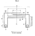
Fig. 4] Fig. 4 is a schematic view showing a cross section in a tire width direction of the tire 1 according to the first modification example. - [
Fig. 5] Fig. 5 is a schematic view showing a cross section in a tire width direction of the tire 1 according to the second modification example. - Hereinafter, the tire according to the embodiment of the present invention will be described. Note that, in the following description of the drawings, the same or similar reference numerals are used to designate the same or similar parts.
- It will be appreciated that the drawings are schematically shown and the ratio and the like of each dimension are different from the real ones. Therefore, a specific dimension should be determined in diagram of the following description. Moreover, among the drawings, the respective dimensional relations or ratios may differ.
- A tire according to the embodiments is provided with one pair of bead cores, a carcass layer having a toroidal shape that extends between such one pair of bead cores, and a belt layer disposed so as to be adjacent to the carcass layer. The carcass layer is folded back to the outside in a tire width direction at the bead core. The carcass layer folded back in the bead cores is disposed so as to be overlapped in a tread portion having a tire stepping surface. The carcass layer is formed of a plurality of carcass cords, each of which has an inclination of 30 degrees or more and 50 degrees or less with respect to a tire circumferential direction.
- In the embodiment, the inclination of the carcass cord with respect to the tire circumferential direction is 30 degree or more, and thus, a rigidity with respect to a shear stress in the tire width direction can be ensured by the carcass layer. The rigidity with respect to the shear stress is ensured by the carcass layer, and thus, even if at least one belt layer is eliminated from among a plurality of belt layers, the rigidity with respect to the shear stress in the tire width direction is ensured as a whole of the tire.
- In the embodiments, the inclination of the carcass cord with respect to the tire circumferential direction is 50 degree or less, and thus, lowering of steering stability is restrained.
- Hereinafter, a tire according to the first embodiment will be described with reference to the drawings.
Fig. 1 is a perspective view showing a tire 1 according to the first embodiment. InFig. 1 , it should be kept in mind that a part of the tire 1 is eliminated in order to show an internal structure of the tire 1.Fig. 2 is a schematic view showing a cross section in a tire width direction of the tire 1 according to the first embodiment.Fig. 3 is a schematic view when the tire 1 according to the first embodiment is seen from the outside in a tire radial direction. - As shown in
Fig. 1 , a pneumatic tire 1 is provided with one pair ofbead portions 10, acarcass layer 20, atread portion 30, abelt layer 40, and aside wall portion 50. - A
bead portion 10 has abard core 12 and abead filler 14. Thebead core 12 is provided in order to fix the tire 1 to a rim (not shown). Thebead core 12 is configured by bead wires (not shown). Thebead filler 14 is provided in order to enhance a rigidity of thebead portion 10. - First, the
carcass layer 20 has a toroidal shape that extends between one pair ofbead portions 10. Thecarcass layer 20, as shown inFig. 2 , is folded back to the outside in the tire width direction. In more detail, thecarcass layer 20 is folded back while enveloping thebead core 12 and thebead filler 14. Thecarcass layer 20 folded back at thebead core 12 is disposed so as to be overlapped in atread portion 30. In more detail, thecarcass layer 20 has anoutside carcass layer 20A that is folded back at onebead core 12, anoutside carcass layer 20B that is folded back at theother bead core 12, and aninside carcass layer 20C that is positioned at the inside in the tire radial direction or in the tire width direction with respect to the outside carcass later 20A and theoutside carcass layer 20B. Theoutside carcass layer 20A and theoutside carcass layer 20B constitute anoverlap region 20D in which these two layers are to be overlapped with each other at thetread portion 30. - Here, as shown in
Fig. 2 andFig. 3 , in the tire width direction, it is preferable that an overlap width X (a width X of theoverlap region 20D) of thecarcass layer 20 folded back at thebead core 12 be 1/3 or more of a width Y of abelt layer 40. - Second, the
carcass layer 20, as shown inFig. 3 , is formed of a plurality of carcass cords 21, each of which has an inclination θ with respect to the tire circumferential direction (a equator centerline CL). The inclination 8 of the carcass cord 21 with respect to the tire circumferential direction is 30 degree or more and 50 degree or less. It should be kept in mind that thecarcass cord 21A forming theoutside carcass layer 20A and thecarcass cord 21B forming theoutside carcass layer 20B cross each other in theoverlap region 20D. - The carcass cord 21 is configured by an organic fiber such as a PET (Polyethylene Terephthalate) or a nylon. In the cord direction, a treat tensile rigidity of one
carcass layer 20 is 90 kgf/mm2 or more and 300 kgf/mm2. It is preferable that a rigidity of one carcass cord 21 be 330 kgf/mm2 or more and 526 kgf/mm2 or less. In addition, it is preferable that the number of spikes of the carcass cord 21 per width of 50 mm be 30 to 65. - Here, the treat tensile rigidity (EL) of the
carcass layer 20 in the cord direction of the carcass cord 21 is calculated by the formula of EL = Ef x vf + Em x (1- vf). - In the formula, Ef is a rigidity (Young's modulus) of the carcass cord 21, Em is a rigidity (Young's modulus) of a rubber covering the carcass cord 21, and vf is a percentage of the carcass cord 21 included in unit volume of the carcass cord 21 covered with the rubber (a volume content of the cord).
- It is to be noted that vf is calculated by the formula of vf = (πr2/4 x N)/(r x 50). In the formula, r is a radius of the carcass cord 21.
- Turning to
Fig. 1 , thetread portion 30 has a tire stepping surface. Thetread portion 30 is configured by a plurality of blocks divided by a circumferential groove or a widthwise groove. - The
belt layer 40 is positioned at the outside in the tire radial direction with respect to the carcass layer 20 (theoutside carcass layer 20A and theoutside carcass layer 20B). In addition, thebelt layer 40, as shown inFig. 3 , has a plurality ofbelt cords 41. The plurality ofbelt cords 41 each have an inclination of -10 degree or more and 0 degree or less with respect to the tire circumferential direction (the equator centerline CL). It is to be noted that such an angle is defined so that the right turn is the positive direction "+", and the left turn is the negative direction "-", with respect to the tire circumferential direction (the equator centerline CL). - A
belt cord 41 is configured by a steel or a Kevlar fiber. In the tire circumferential direction, the treat tensile rigidity of thebelt layer 40 is 750 kgf/mm2 or more. The treat tensile strength of thebelt layer 40 per width of 50 mm is 2,100 kgf or more. It is preferable that the strength of onebelt cord 41 be larger than the strength of one carcass cord 21. It is preferable that the rigidity of onebelt cord 41 be 526 kgf or more/mm2 or more and the strength of onebelt cord 41 be 50 kgf or more. It is preferable that the number of spikes of thebelt cord 41 per 50 mm be 30 to 65. - Here, the treat tensile rigidity (EL) of the
belt layer 40 in the cord direction is calculated by the formula of EL = Ef x vf x Em x (1 - vf). - In the formula, Ef is a rigidity (Young's modulus) of the
belt cord 41, Em is a rigidity (Young's modulus) of a rubber covering thebelt cord 41, and vf is a percentage of thebelt cord 41 included per portion volume of thebelt cord 41 covered with the rubber (a volume content of the cord). - It is to be noted that vf is calculated by the formula of vf = (πr2/4 x N)/(r x 50). In the formula, r is a radius of the
belt cord 41. - In addition, the treat tensile rigidity (ET) of the
belt layer 40 in an orthogonal direction with respect to the cord direction of thebelt cord 41 is calculated by the formula of ET = 4/3 x Em (1- vf). - Further, a treat tensile rigidity (Exx) of the
belt layer 40 in the tire circumferential direction is calculated by Exx = EL cos4θ + ET. In the formula, 0 is an inclination of thebelt cord 41 with respect to the tire circumferential direction. - Turning to
Fig. 1 , aside wall portion 50 is formed at both ends in the tire width direction of thetread portion 30. Theside wall portion 50 is positioned between thebead portion 10 and thetread portion 30. - In the first embodiment, the inclination of the carcass cord 21 with respect to the tire circumferential direction is 30 degree or more and 50 degree or less, and thus, the rigidity with respect to the shear stress in the tire width direction can be ensured by the
carcass layer 20. The rigidity with respect to the shear stress in the tire width direction is ensured by thecarcass layer 20, and thus, even if at least one belt layer is eliminated from among a plurality of belt layers, the rigidity with respect to the shear stress in the tire width direction is ensured as a whole of the tire 1, and lowering of steering stability is restrained. - Hereinafter, Modification Example 1 of the first embodiment will be described with reference to the drawings. Hereinafter, differences from the first embodiment will be mainly described.
- Specifically, in the first embodiment, the
belt layer 40 is positioned at the outside in the tire radial direction with respect to the carcass layer 20 (theoutside carcass layer 20A and theoutside carcass layer 20B). On the other hand, in Modification Example 1, thebelt layer 40 is positioned at the inside in the tire radial direction with respect to theoutside carcass layer 20A and theoutside carcass layer 20B, and is positioned at the inside in the tire radial direction with respect to theinside carcass layer 20C. - In Modification Example 1, the
belt layer 40 is disposed between theoutside carcass layer 20A and theoutside carcass layer 20B and theinside carcass layer 20C, and thus, thebelt cord 41 provided in thebelt layer 40 is protected by thecarcass layer 20. Therefore, a cutting durability of thebelt cord 41 is improved. - Hereinafter, Modification Example 2 of the first embodiment will be described with reference to the drawings. Hereinafter, differences from the first embodiment will be mainly described.
- Specifically, in the first embodiment, the
belt layer 40 was described by way of example of a case in which the belt layer is made of one layer. On the other hand, in Modification Example 2, a tire, as shown inFig. 5 , has, as abelt layer 40, afirst belt layer 40A and asecond belt layer 40B that is disposed so as to be adjacent to thefirst belt layer 40A in a tire radial direction. That is, thebelt layer 40 is configured by thefirst belt layer 40A and thesecond belt layer 40B. It is to be noted that thesecond belt layer 40B is disposed at the outside in the tire radial direction with respect to thefirst belt layer 40A. - The
second belt layer 40B has a plurality of belt cords 41B, each of which has an inclination of a predetermined angle with respect to a tire circumferential direction. It is preferable that the predetermined angle be -10 degree or more and 0 degree or less with respect to the tire circumferential direction (the equator centerline CL). - On the other hand, the
first belt layer 40A has a plurality of belt cords 41A, each of which has an inclination larger than the predetermined angle with respect to the tire circumferential direction (the equator centerline CL). It is preferable that the plurality of belt cords 41A each have an inclination of 0 degree or more and 80 degree or less with respect to the tire circumferential direction (the equator centerline CL), and it is more preferable that the above belt cords each have an inclination of 10 degree or more and 30 degree or less. - In Modification Example 2, the
first belt layer 40A and thesecond belt layer 40B are provided. The inclination of each of the plurality of belt cords 41A in thefirst belt layer 40A is larger than the inclination of each of the plurality of belt cords 41B in thesecond belt layer 40B. Therefore, in Modification Example 2, the rigidity with respect to the shear stress in the tire width direction is ensured by thefirst belt layer 40A, and thus, the rigidity with respect to the shear stress in the tire width direction is ensured as a whole of the tire 1, and lowering of steering stability is further restrained. - While in Modification Example 2, the
second belt layer 40B was described by way of example of a case in which the second belt layer is disposed at the outside in the tire radial direction with respect to thefirst belt layer 40A, this layer is not limited thereto. Thesecond belt layer 40B may be disposed at the inside in the tire radial direction with respect to thefirst belt layer 40A. - Hereinafter, Evaluation Result 1 will be described. In Evaluation Result 1, as shown in Table 1, an index evaluation was subjectively made as to the steering stability by means of a cruising test of a vehicle by mounting tires to the vehicle, the tires being different from each other in terms of the inclination of the carcass cord with respect to the tire circumferential direction. It is to be noted that an index 100 is an index of steering stability corresponding to a tire in which the carcass layer is not overlapped in the tread portion and in which no belt layer is eliminated. It is also to be noted that in Examples and Comparative Examples, the tires having a similar structure to that of the embodiment are employed except the values shown in Table 1. In addition, the tire size used is "155/65R13".
-

- As shown in Table 1, in Example 11 to Example 13, the inclination θ of the carcass cord with respect to the tire circumferential direction is in the range of 30 degree or more and 50 degree or less, and thus, it was verified that lowering of steering stability is restrained. On the other hand, in Comparative Example 11 and Comparative Example 12, the inclination θ of the carcass cord with respect to the tire circumferential direction is out of the range of 30 degree or more and 50 degree or less, and thus, it was verified that steering stability remarkably lowers.
- Hereinafter, Evaluation Result 2 will be described. In Evaluation Result 2, as shown in Table 2, an index evaluation was subjectively made as to the steering stability by means of a cruising test of a vehicle by mounting tires to the vehicle, the tires being different from each other in terms of the treat tensile rigidity of one carcass layer, the rigidity of one carcass cord (the cord rigidity), material for carcass cord, the number of spikes of the carcass cord per width of 50 mm, and diameter of the carcass cord (cord diameter). It is to be noted that the index 100 is an index of steering stability corresponding to the tires in which no carcass layer is overlapped in the tread portion and in which no belt layer is eliminated. It is also to be noted that in Examples and Comparative Examples, the tires having a similar structure to that of the embodiments are employed except the values shown in Table 2. In addition, the tire size used is "155/65R13".
-

- As shown in Table 2, first, in Example 20 to Example 24, the treat tensile rigidity of one carcass layer is in the range of 90 kgf/mm2 or more and 300 kgf/mm2 or less, and thus, it was verified that lowering steering stability is restrained. Second, in Example 20 to Example 24, the rigidity of one carcass cord (the cord rigidity) is in the range of 330 kgf/mm2 or more and 526 kgf/mm2 or less, and thus, it was verified that lowering steering stability is restrained. Third, in Example 20 to Example 24, the number of spikes of carcass cord per width of 50 mm is in the range of 30 to 65, and thus, it was verified that lowering steering stability is restrained.
- On the other hand, in Comparative Example 21 and Comparative Example 22, the treat tensile rigidity of one carcass layer is out of the range of 90 kgf/mm2 or more and 300 kgf/mm2 or less, and thus, it was verified that steering stability remarkably lowers. Second, in Comparative Example 20, the rigidity of one carcass cord (the cord rigidity) is out of the range of 330 kgf/mm2 or more and 526 kgf/mm2 or less, and thus, it was verified that steering stability remarkably lowers. Third, in Comparative Example 21, the number of spikes of carcass cord per width of 50 mm is out of the range of 30 to 65, and thus, it was verified that steering stability remarkably lowers.
- Hereinafter, Evaluation Result 3 will be described. In Evaluation Result 3, as shown in Table 3, there were prepared tires which are different from each other in terms of the treat tensile rigidity of one belt layer, the rigidity of one belt cord (the cord rigidity), the treat tensile strength of belt layer per width of 50 mm, in the strength of one belt cord (the cord strength), the material for belt cord, the number of spikes of belt cord per width of 50 mm, the inclination of belt cord with respect to the tire circumferential direction, and the inclination of the belt cord with respect to the tire circumferential direction. First, the growth percentages of the diameters of the tires (an internal pressure growth @ center) were evaluated in the equator centerlines CL by means of a cruising test of a vehicle by mounting these tires to the vehicle. Second, an index evaluation was subjectively made as to the steering stability by means of the cruising test of the vehicle by mounting these tires to the vehicle. It is to be noted that the index 100 is an index corresponding to the tires in which no carcass layer is overlapped in the tread portion and in which no belt layer is eliminated. In addition, the molding properties and weights of these tires were evaluated. Third, an index evaluation was made as to the fracture strength of the tires by means of a hydraulic pressure test by filling water in these tires. It is also to be noted that the index 100 is an index indicating a predetermined standard such as an in-house standard. It is to be further noted that in Examples and Comparative Examples, the tires having a similar structure to that of the embodiment are employed except the values shown in Table 3. In addition, the tire size used is "155/65R13".
-

- As shown in Table 3, first, in Example 30 to Example 34, the treat tensile rigidity of one belt layer is 750 kgf/mm2 or more, and thus, it was verified that lowering of steering stability is restrained. Second, in Example 30 to Example 34, the rigidity of one belt cord (the cord rigidity) is 526kgf or more/mm2 or more, and thus, it was verified that lowering of steering stability is restrained. Third, in Example 30 to Example 34, the treat tensile strength of the belt layer per width of 50 mm is 2,100kgf or more, and thus, it was verified that lowering of fracture strength is restrained. Fourth, in Example 30 to Example 34, the strength of one belt cord (the cord strength) is 50 kgf or more, and thus, it was verified that lowering of fracture strength is restrained. Fifth, in Example 30 to Example 34, the inclination of the belt cord with respect to the tire circumferential direction is in the range of -10 degrees or more and 0 degree or less, and thus, it was verified that the internal pressure growth @ center is restrained. Six, in Example 30 to Example 34, the number of spikes of the belt cord per width of 50 mm is in the range of 30 to 65, and thus, it was verified that lowering of steering stability is restrained.
- In addition, in Example 30 to Example 34, it was verified that a good result is obtained as to the internal pressure growth @ center, and a good result is also obtained as to the fracture strength.
- On the other hand, in Comparative Examples 31 and 32 and Comparative Example 34, the treat tensile rigidity of one belt layer is smaller than 750 kgf/mm2, and thus, it was verified that steering stability lowers. In addition, in Comparative Examples 31 to 33, the treat tensile strength of the belt layer per width of 50 mm is smaller than 2,100 kgf, and thus, it was verified that the fracture strength remarkably lowers.
- Further, in Comparative Examples 34 to 36, the inclination of the belt cord with respect to the tire circumferential direction is out of the range of -10 degree or more and 0 degree or less, and thus, it was verified that a good result is not obtained as to the internal pressure growth @ center.
- In addition, in Comparative Example 31 and Comparative Example 32, it was verified that a good result is not obtained as to the internal pressure growth @ center, and a good result is not obtained as to the fracture strength as well.
- Hereinafter, Evaluation Result 4 will be described. In Evaluation Result 4, as shown in Table 4, there were prepared tires which are different from each other in terms of the overlap width of the carcass layers folded back at the bead core (an overlap width) in the tire width direction. It is to be noted that with respect to the overlap width of the carcass layers, a percentage of the overlap width of the carcass layers with respect to the belt layer in the tire width direction is represented by %. An index evaluation was subjectively made as to the steering stability by means of a cruising test of a vehicle by mounting these tires to the vehicle. It is to be noted that the index 100 is an index of steering stability corresponding to the tire in which no carcass layer is overlapped in the tread portion and in which no belt layer is eliminated. In addition, the molding properties and weights of these tires were evaluated. It is to be noted that in Examples and Comparative Examples, the tires having a similar structure to that of the embodiments are employed except the values shown in Table 4. In addition, the tire size used is "155/65R13".
-

- As shown in Table 4, in Examples 40 and 41, the overlap width of the carcass layers with respect to the belt layer is 30% or more, and thus, it was verified that lowering of steering stability is restrained. In addition, it was verified that good results are obtained as to the molding properties and weights of the tires as well.
- On the other hand, in Comparative Example 41, the overlap width of the carcass layers with respect to the belt layer is smaller than 30%, and thus, it was verified that steering stability remarkably lowers. In addition, it was verified that a good result is not obtained as to the molding properties of the tires. In Comparative Example 42, the overlap width of the carcass layers with respect to the belt layer is 100%, and thus, it was verified that a good result is not obtained as to the weights of the tires.
- Hereinafter, Evaluation Result 5 will be described. In Evaluation Result 5, as shown in Table 5, there were prepared a tire with one belt layer and a tire with two belt layers in the tire width direction. It is to be noted that the tire with two belt layers is assumed to have a first belt layer and a second belt layer that is disposed so as to be outer in tire radial direction than the first belt layer. Hereinafter, a description will be given, assuming that an inclination with respect to the tire circumferential direction (the equator centerline CL) of a plurality of belt cords in the first belt layer is a first inclination. On the other hand, a description will be given, assuming that an inclination with respect to the tire circumferential direction (the equator centerline CL) of a plurality of belt cords in the second belt layer is a second inclination. In addition, in Evaluation Result 5, tires which are different from each other in terms of the angle of the first inclination were prepared.
- In addition, steering stabilities of these tires were evaluated by index by employing a testing instrument for a flat belt system. It is to be noted that the index 100 is an index of steering stability corresponding to the tires in which no carcass layer is overlapped in the tread portion and in which no belt layer is eliminated. In addition, the molding properties and weights of these tires were evaluated. It is also to be noted that in Examples and Comparative Examples, the tires having a similar structure to that of the embodiments are employed except the values shown in Table 5. In addition, the tire width used is "255/45R17".
-

- As shown in Table 5, in Example 51 to Example 54, the angle of the first inclination is larger than the angle of the second inclination, and thus, it was verified that lowering of steering stability is restrained. In addition, it was verified that a good result is obtained as to the weight of the tire as well. It is to be noted that in Example 55, a predetermined advantageous effect is attained as to the weight of the tire, whereas an advantageous effect is low as to steering stability. Namely, it was verified that if the angle of the first inclination is an angle of 10 degrees or more and 40 degrees or less, a good result is obtained as to each of the steering stability and the weight of the tire.
- On the other hand, in Comparative Example 51 to Comparative Example 53, the angle of the first inclination is equal to or smaller than the angle of the second inclination, and thus, it was verified that an advantageous effect of restraining steering stability lowers.
- The present invention has been described according to the aforementioned embodiments. However, it must not be understood that the discussions and the drawings constituting a part of this disclosure limit the present invention. From this disclosure, various alternative embodiments, examples and operational techniques are apparent to those skilled in the art.
- Note that the entire content of the Japanese Patent Application No.
2011-118163 (filed on May 26, 2011 - As described above, the present invention can provide a tire that is capable of reducing at least one belt layer of a plurality of belt layers while ensuring a rigidity with respect to a shear stress in a tire width direction.
Claims (5)
- A tire comprising one pair of bead cores, a carcass layer having a toroidal shape that extends between said one pair of bead cores, and a belt layer disposed so as to be adjacent to the carcass layer, wherein
the carcass layer is folded back to an outside in a tire width direction at the bead core,
the carcass layer folded back at the bead core is disposed so as to be overlapped in a tread portion having a tire stepping surface, and
the carcass layer is formed of a plurality of carcass cords, each of which has an inclination of 30 degrees or more and 50 degrees or less with respect to a tire circumferential direction. - The tire according to claim 1, wherein in a direction in which the carcass cords extend, a treat tensile rigidity of the carcass layer is 90 kgf/mm2 or more and 300 kgf/mm2 or less.
- The tire according to claim 1, wherein in a tire width direction, an overlap width of the carcass layer that is folded back at the bead core is 1/3 or more of a width of the belt layer.
- The tire according to claim 1, wherein the belt layer has a plurality of belt cords, each of which has an inclination of -10 degrees or more and 0 degree or less with respect to the tire circumferential direction,
in the tire circumferential direction, a treat tensile rigidity of the belt layer is 750 kgf/mm2 or more, and
a treat tensile strength per width of 50 mm is 2,100 kgf or more. - A pneumatic tire according to claim 1, having a first belt layer and a second belt layer as the belt layer, the second belt layer being disposed so as to be adjacent to the first belt layer in a tire radial direction, wherein
the second belt layer has a plurality of belt cords, each of which has a predetermined inclination with respect to the tire circumferential direction, and
the first belt layer has a plurality of belt cords, each of which has an inclination that is larger than the predetermined angle with respect to the tire circumferential direction.
Applications Claiming Priority (2)
| Application Number | Priority Date | Filing Date | Title |
|---|---|---|---|
| JP2011118163 | 2011-05-26 | ||
| PCT/JP2012/063556 WO2012161331A1 (en) | 2011-05-26 | 2012-05-25 | Tire |
Publications (3)
| Publication Number | Publication Date |
|---|---|
| EP2716475A1 true EP2716475A1 (en) | 2014-04-09 |
| EP2716475A4 EP2716475A4 (en) | 2015-01-21 |
| EP2716475B1 EP2716475B1 (en) | 2018-10-31 |
Family
ID=47217395
Family Applications (1)
| Application Number | Title | Priority Date | Filing Date |
|---|---|---|---|
| EP12790356.5A Not-in-force EP2716475B1 (en) | 2011-05-26 | 2012-05-25 | Tire |
Country Status (5)
| Country | Link |
|---|---|
| US (1) | US20140124117A1 (en) |
| EP (1) | EP2716475B1 (en) |
| JP (1) | JP5944895B2 (en) |
| CN (1) | CN103561970A (en) |
| WO (1) | WO2012161331A1 (en) |
Cited By (1)
| Publication number | Priority date | Publication date | Assignee | Title |
|---|---|---|---|---|
| EP4335660A1 (en) * | 2022-09-08 | 2024-03-13 | Continental Reifen Deutschland GmbH | Vehicle tire construction |
Families Citing this family (9)
| Publication number | Priority date | Publication date | Assignee | Title |
|---|---|---|---|---|
| WO2015047780A1 (en) | 2013-09-24 | 2015-04-02 | Bridgestone Americas Tire Operations, Llc | Tire with toroidal element |
| EP3307559B1 (en) | 2015-06-15 | 2021-02-17 | Bridgestone Americas Tire Operations, LLC | Tire having a conductivity path |
| JP2017074805A (en) * | 2015-10-13 | 2017-04-20 | 住友ゴム工業株式会社 | Pneumatic tire |
| JP6878774B2 (en) * | 2016-05-12 | 2021-06-02 | 横浜ゴム株式会社 | Pneumatic tires |
| JP6245304B2 (en) * | 2016-05-12 | 2017-12-13 | 横浜ゴム株式会社 | Pneumatic tire |
| JP6245303B2 (en) * | 2016-05-12 | 2017-12-13 | 横浜ゴム株式会社 | Pneumatic tire |
| JP6715081B2 (en) * | 2016-05-20 | 2020-07-01 | 株式会社ブリヂストン | Pneumatic tire |
| CN108859616A (en) * | 2018-07-12 | 2018-11-23 | 万力轮胎股份有限公司 | A kind of run-flat tire |
| CN119590146A (en) * | 2024-12-10 | 2025-03-11 | 沈阳和平特种轮胎有限公司 | A lightweight bias carcass structure suitable for small-sized aviation tires |
Family Cites Families (8)
| Publication number | Priority date | Publication date | Assignee | Title |
|---|---|---|---|---|
| DE1262580B (en) * | 1962-09-08 | 1968-03-07 | Continental Gummi Werke Ag | Blank for pneumatic vehicle tires, especially two-layer tires |
| FR2238603B1 (en) * | 1973-07-27 | 1976-06-18 | Uniroyal | |
| JPS63110003A (en) * | 1986-10-25 | 1988-05-14 | Bridgestone Corp | Bias pneumatic tire for motorcycle |
| JP3078589B2 (en) * | 1991-04-05 | 2000-08-21 | 株式会社ブリヂストン | Off-road tires for motorcycles |
| JP2628953B2 (en) * | 1991-12-27 | 1997-07-09 | 住友ゴム工業株式会社 | Radial tires for motorcycles |
| EP0635383B1 (en) * | 1993-07-19 | 1997-11-12 | Bridgestone Corporation | Pneumatic tire |
| JP3537916B2 (en) * | 1995-06-06 | 2004-06-14 | 株式会社ブリヂストン | Combination of pneumatic semi-radial tires |
| JP3648009B2 (en) * | 1997-01-24 | 2005-05-18 | 株式会社ブリヂストン | Installation method of pneumatic tire |
-
2012
- 2012-05-25 CN CN201280025611.0A patent/CN103561970A/en active Pending
- 2012-05-25 US US14/122,393 patent/US20140124117A1/en not_active Abandoned
- 2012-05-25 EP EP12790356.5A patent/EP2716475B1/en not_active Not-in-force
- 2012-05-25 JP JP2013516467A patent/JP5944895B2/en not_active Expired - Fee Related
- 2012-05-25 WO PCT/JP2012/063556 patent/WO2012161331A1/en not_active Ceased
Cited By (1)
| Publication number | Priority date | Publication date | Assignee | Title |
|---|---|---|---|---|
| EP4335660A1 (en) * | 2022-09-08 | 2024-03-13 | Continental Reifen Deutschland GmbH | Vehicle tire construction |
Also Published As
| Publication number | Publication date |
|---|---|
| JP5944895B2 (en) | 2016-07-05 |
| US20140124117A1 (en) | 2014-05-08 |
| EP2716475B1 (en) | 2018-10-31 |
| WO2012161331A1 (en) | 2012-11-29 |
| EP2716475A4 (en) | 2015-01-21 |
| CN103561970A (en) | 2014-02-05 |
| JPWO2012161331A1 (en) | 2014-07-31 |
Similar Documents
| Publication | Publication Date | Title |
|---|---|---|
| EP2716475B1 (en) | Tire | |
| EP3305550B1 (en) | Reinforcement member for tires, and tire using same | |
| JP5587739B2 (en) | Pneumatic tire | |
| JP2012061892A (en) | Heavy duty tire | |
| EP2018978A1 (en) | Pneumatic tire | |
| US20190283503A1 (en) | Rubber-cord composite, reinforcing member for tires, and tire using same | |
| JP2011189873A (en) | Pneumatic tire | |
| US8146339B2 (en) | Steel cord for reinforcing rubber article and pneumatic radial tire | |
| EP3549787A1 (en) | Rubber cord composite, reinforcing member for tires, and tire using same | |
| JP6078949B2 (en) | Pneumatic radial tire | |
| CN106232395A (en) | Side enhancement mode run-flat radial | |
| EP3812169A1 (en) | Tire | |
| JPWO2015156154A1 (en) | tire | |
| EP3546246B1 (en) | Tire | |
| EP3546245B1 (en) | Tire | |
| JP2011025798A (en) | Pneumatic tire | |
| JP2010089725A (en) | Pneumatic tire for automobile | |
| EP3643539A1 (en) | Run-flat tire | |
| EP3643537A1 (en) | Run-flat tire | |
| JP2007326418A (en) | Pneumatic radial tire | |
| JP2009149176A (en) | Pneumatic tire | |
| CN109715411B (en) | Bias tire | |
| EP3643538A1 (en) | Run-flat tire | |
| JP2009202685A (en) | Pneumatic tire | |
| EP3546247B1 (en) | Tire |
Legal Events
| Date | Code | Title | Description |
|---|---|---|---|
| PUAI | Public reference made under article 153(3) epc to a published international application that has entered the european phase |
Free format text: ORIGINAL CODE: 0009012 |
|
| 17P | Request for examination filed |
Effective date: 20131212 |
|
| AK | Designated contracting states |
Kind code of ref document: A1 Designated state(s): AL AT BE BG CH CY CZ DE DK EE ES FI FR GB GR HR HU IE IS IT LI LT LU LV MC MK MT NL NO PL PT RO RS SE SI SK SM TR |
|
| DAX | Request for extension of the european patent (deleted) | ||
| A4 | Supplementary search report drawn up and despatched |
Effective date: 20141219 |
|
| RIC1 | Information provided on ipc code assigned before grant |
Ipc: B60C 9/06 20060101AFI20141215BHEP Ipc: B60C 15/00 20060101ALI20141215BHEP |
|
| STAA | Information on the status of an ep patent application or granted ep patent |
Free format text: STATUS: EXAMINATION IS IN PROGRESS |
|
| 17Q | First examination report despatched |
Effective date: 20171010 |
|
| REG | Reference to a national code |
Ref country code: DE Ref legal event code: R079 Ref document number: 602012052942 Country of ref document: DE Free format text: PREVIOUS MAIN CLASS: B60C0009060000 Ipc: B60C0009220000 |
|
| RIC1 | Information provided on ipc code assigned before grant |
Ipc: B60C 15/00 20060101ALI20180424BHEP Ipc: B60C 9/06 20060101ALI20180424BHEP Ipc: B60C 9/20 20060101ALN20180424BHEP Ipc: B60C 9/22 20060101AFI20180424BHEP |
|
| GRAP | Despatch of communication of intention to grant a patent |
Free format text: ORIGINAL CODE: EPIDOSNIGR1 |
|
| STAA | Information on the status of an ep patent application or granted ep patent |
Free format text: STATUS: GRANT OF PATENT IS INTENDED |
|
| INTG | Intention to grant announced |
Effective date: 20180606 |
|
| GRAS | Grant fee paid |
Free format text: ORIGINAL CODE: EPIDOSNIGR3 |
|
| GRAA | (expected) grant |
Free format text: ORIGINAL CODE: 0009210 |
|
| STAA | Information on the status of an ep patent application or granted ep patent |
Free format text: STATUS: THE PATENT HAS BEEN GRANTED |
|
| AK | Designated contracting states |
Kind code of ref document: B1 Designated state(s): AL AT BE BG CH CY CZ DE DK EE ES FI FR GB GR HR HU IE IS IT LI LT LU LV MC MK MT NL NO PL PT RO RS SE SI SK SM TR |
|
| REG | Reference to a national code |
Ref country code: CH Ref legal event code: EP Ref country code: GB Ref legal event code: FG4D |
|
| REG | Reference to a national code |
Ref country code: AT Ref legal event code: REF Ref document number: 1058913 Country of ref document: AT Kind code of ref document: T Effective date: 20181115 |
|
| REG | Reference to a national code |
Ref country code: DE Ref legal event code: R096 Ref document number: 602012052942 Country of ref document: DE |
|
| REG | Reference to a national code |
Ref country code: IE Ref legal event code: FG4D |
|
| REG | Reference to a national code |
Ref country code: NL Ref legal event code: MP Effective date: 20181031 |
|
| REG | Reference to a national code |
Ref country code: LT Ref legal event code: MG4D |
|
| REG | Reference to a national code |
Ref country code: AT Ref legal event code: MK05 Ref document number: 1058913 Country of ref document: AT Kind code of ref document: T Effective date: 20181031 |
|
| PG25 | Lapsed in a contracting state [announced via postgrant information from national office to epo] |
Ref country code: FI Free format text: LAPSE BECAUSE OF FAILURE TO SUBMIT A TRANSLATION OF THE DESCRIPTION OR TO PAY THE FEE WITHIN THE PRESCRIBED TIME-LIMIT Effective date: 20181031 Ref country code: NO Free format text: LAPSE BECAUSE OF FAILURE TO SUBMIT A TRANSLATION OF THE DESCRIPTION OR TO PAY THE FEE WITHIN THE PRESCRIBED TIME-LIMIT Effective date: 20190131 Ref country code: AT Free format text: LAPSE BECAUSE OF FAILURE TO SUBMIT A TRANSLATION OF THE DESCRIPTION OR TO PAY THE FEE WITHIN THE PRESCRIBED TIME-LIMIT Effective date: 20181031 Ref country code: LV Free format text: LAPSE BECAUSE OF FAILURE TO SUBMIT A TRANSLATION OF THE DESCRIPTION OR TO PAY THE FEE WITHIN THE PRESCRIBED TIME-LIMIT Effective date: 20181031 Ref country code: IS Free format text: LAPSE BECAUSE OF FAILURE TO SUBMIT A TRANSLATION OF THE DESCRIPTION OR TO PAY THE FEE WITHIN THE PRESCRIBED TIME-LIMIT Effective date: 20190228 Ref country code: ES Free format text: LAPSE BECAUSE OF FAILURE TO SUBMIT A TRANSLATION OF THE DESCRIPTION OR TO PAY THE FEE WITHIN THE PRESCRIBED TIME-LIMIT Effective date: 20181031 Ref country code: LT Free format text: LAPSE BECAUSE OF FAILURE TO SUBMIT A TRANSLATION OF THE DESCRIPTION OR TO PAY THE FEE WITHIN THE PRESCRIBED TIME-LIMIT Effective date: 20181031 Ref country code: PL Free format text: LAPSE BECAUSE OF FAILURE TO SUBMIT A TRANSLATION OF THE DESCRIPTION OR TO PAY THE FEE WITHIN THE PRESCRIBED TIME-LIMIT Effective date: 20181031 Ref country code: BG Free format text: LAPSE BECAUSE OF FAILURE TO SUBMIT A TRANSLATION OF THE DESCRIPTION OR TO PAY THE FEE WITHIN THE PRESCRIBED TIME-LIMIT Effective date: 20190131 Ref country code: HR Free format text: LAPSE BECAUSE OF FAILURE TO SUBMIT A TRANSLATION OF THE DESCRIPTION OR TO PAY THE FEE WITHIN THE PRESCRIBED TIME-LIMIT Effective date: 20181031 |
|
| PG25 | Lapsed in a contracting state [announced via postgrant information from national office to epo] |
Ref country code: AL Free format text: LAPSE BECAUSE OF FAILURE TO SUBMIT A TRANSLATION OF THE DESCRIPTION OR TO PAY THE FEE WITHIN THE PRESCRIBED TIME-LIMIT Effective date: 20181031 Ref country code: SE Free format text: LAPSE BECAUSE OF FAILURE TO SUBMIT A TRANSLATION OF THE DESCRIPTION OR TO PAY THE FEE WITHIN THE PRESCRIBED TIME-LIMIT Effective date: 20181031 Ref country code: GR Free format text: LAPSE BECAUSE OF FAILURE TO SUBMIT A TRANSLATION OF THE DESCRIPTION OR TO PAY THE FEE WITHIN THE PRESCRIBED TIME-LIMIT Effective date: 20190201 Ref country code: RS Free format text: LAPSE BECAUSE OF FAILURE TO SUBMIT A TRANSLATION OF THE DESCRIPTION OR TO PAY THE FEE WITHIN THE PRESCRIBED TIME-LIMIT Effective date: 20181031 Ref country code: NL Free format text: LAPSE BECAUSE OF FAILURE TO SUBMIT A TRANSLATION OF THE DESCRIPTION OR TO PAY THE FEE WITHIN THE PRESCRIBED TIME-LIMIT Effective date: 20181031 Ref country code: PT Free format text: LAPSE BECAUSE OF FAILURE TO SUBMIT A TRANSLATION OF THE DESCRIPTION OR TO PAY THE FEE WITHIN THE PRESCRIBED TIME-LIMIT Effective date: 20190301 |
|
| PG25 | Lapsed in a contracting state [announced via postgrant information from national office to epo] |
Ref country code: IT Free format text: LAPSE BECAUSE OF FAILURE TO SUBMIT A TRANSLATION OF THE DESCRIPTION OR TO PAY THE FEE WITHIN THE PRESCRIBED TIME-LIMIT Effective date: 20181031 Ref country code: CZ Free format text: LAPSE BECAUSE OF FAILURE TO SUBMIT A TRANSLATION OF THE DESCRIPTION OR TO PAY THE FEE WITHIN THE PRESCRIBED TIME-LIMIT Effective date: 20181031 Ref country code: DK Free format text: LAPSE BECAUSE OF FAILURE TO SUBMIT A TRANSLATION OF THE DESCRIPTION OR TO PAY THE FEE WITHIN THE PRESCRIBED TIME-LIMIT Effective date: 20181031 |
|
| REG | Reference to a national code |
Ref country code: DE Ref legal event code: R097 Ref document number: 602012052942 Country of ref document: DE |
|
| PG25 | Lapsed in a contracting state [announced via postgrant information from national office to epo] |
Ref country code: SM Free format text: LAPSE BECAUSE OF FAILURE TO SUBMIT A TRANSLATION OF THE DESCRIPTION OR TO PAY THE FEE WITHIN THE PRESCRIBED TIME-LIMIT Effective date: 20181031 Ref country code: EE Free format text: LAPSE BECAUSE OF FAILURE TO SUBMIT A TRANSLATION OF THE DESCRIPTION OR TO PAY THE FEE WITHIN THE PRESCRIBED TIME-LIMIT Effective date: 20181031 Ref country code: RO Free format text: LAPSE BECAUSE OF FAILURE TO SUBMIT A TRANSLATION OF THE DESCRIPTION OR TO PAY THE FEE WITHIN THE PRESCRIBED TIME-LIMIT Effective date: 20181031 Ref country code: SK Free format text: LAPSE BECAUSE OF FAILURE TO SUBMIT A TRANSLATION OF THE DESCRIPTION OR TO PAY THE FEE WITHIN THE PRESCRIBED TIME-LIMIT Effective date: 20181031 |
|
| PLBE | No opposition filed within time limit |
Free format text: ORIGINAL CODE: 0009261 |
|
| STAA | Information on the status of an ep patent application or granted ep patent |
Free format text: STATUS: NO OPPOSITION FILED WITHIN TIME LIMIT |
|
| 26N | No opposition filed |
Effective date: 20190801 |
|
| PG25 | Lapsed in a contracting state [announced via postgrant information from national office to epo] |
Ref country code: SI Free format text: LAPSE BECAUSE OF FAILURE TO SUBMIT A TRANSLATION OF THE DESCRIPTION OR TO PAY THE FEE WITHIN THE PRESCRIBED TIME-LIMIT Effective date: 20181031 |
|
| REG | Reference to a national code |
Ref country code: CH Ref legal event code: PL |
|
| GBPC | Gb: european patent ceased through non-payment of renewal fee |
Effective date: 20190525 |
|
| PG25 | Lapsed in a contracting state [announced via postgrant information from national office to epo] |
Ref country code: CH Free format text: LAPSE BECAUSE OF NON-PAYMENT OF DUE FEES Effective date: 20190531 Ref country code: MC Free format text: LAPSE BECAUSE OF FAILURE TO SUBMIT A TRANSLATION OF THE DESCRIPTION OR TO PAY THE FEE WITHIN THE PRESCRIBED TIME-LIMIT Effective date: 20181031 Ref country code: LI Free format text: LAPSE BECAUSE OF NON-PAYMENT OF DUE FEES Effective date: 20190531 |
|
| REG | Reference to a national code |
Ref country code: BE Ref legal event code: MM Effective date: 20190531 |
|
| PG25 | Lapsed in a contracting state [announced via postgrant information from national office to epo] |
Ref country code: LU Free format text: LAPSE BECAUSE OF NON-PAYMENT OF DUE FEES Effective date: 20190525 |
|
| PG25 | Lapsed in a contracting state [announced via postgrant information from national office to epo] |
Ref country code: TR Free format text: LAPSE BECAUSE OF FAILURE TO SUBMIT A TRANSLATION OF THE DESCRIPTION OR TO PAY THE FEE WITHIN THE PRESCRIBED TIME-LIMIT Effective date: 20181031 |
|
| PG25 | Lapsed in a contracting state [announced via postgrant information from national office to epo] |
Ref country code: GB Free format text: LAPSE BECAUSE OF NON-PAYMENT OF DUE FEES Effective date: 20190525 Ref country code: IE Free format text: LAPSE BECAUSE OF NON-PAYMENT OF DUE FEES Effective date: 20190525 |
|
| PG25 | Lapsed in a contracting state [announced via postgrant information from national office to epo] |
Ref country code: BE Free format text: LAPSE BECAUSE OF NON-PAYMENT OF DUE FEES Effective date: 20190531 |
|
| PGFP | Annual fee paid to national office [announced via postgrant information from national office to epo] |
Ref country code: DE Payment date: 20200520 Year of fee payment: 9 Ref country code: FR Payment date: 20200522 Year of fee payment: 9 |
|
| PG25 | Lapsed in a contracting state [announced via postgrant information from national office to epo] |
Ref country code: CY Free format text: LAPSE BECAUSE OF FAILURE TO SUBMIT A TRANSLATION OF THE DESCRIPTION OR TO PAY THE FEE WITHIN THE PRESCRIBED TIME-LIMIT Effective date: 20181031 |
|
| PG25 | Lapsed in a contracting state [announced via postgrant information from national office to epo] |
Ref country code: MT Free format text: LAPSE BECAUSE OF FAILURE TO SUBMIT A TRANSLATION OF THE DESCRIPTION OR TO PAY THE FEE WITHIN THE PRESCRIBED TIME-LIMIT Effective date: 20181031 Ref country code: HU Free format text: LAPSE BECAUSE OF FAILURE TO SUBMIT A TRANSLATION OF THE DESCRIPTION OR TO PAY THE FEE WITHIN THE PRESCRIBED TIME-LIMIT; INVALID AB INITIO Effective date: 20120525 |
|
| REG | Reference to a national code |
Ref country code: DE Ref legal event code: R119 Ref document number: 602012052942 Country of ref document: DE |
|
| PG25 | Lapsed in a contracting state [announced via postgrant information from national office to epo] |
Ref country code: DE Free format text: LAPSE BECAUSE OF NON-PAYMENT OF DUE FEES Effective date: 20211201 |
|
| PG25 | Lapsed in a contracting state [announced via postgrant information from national office to epo] |
Ref country code: FR Free format text: LAPSE BECAUSE OF NON-PAYMENT OF DUE FEES Effective date: 20210531 |
|
| PG25 | Lapsed in a contracting state [announced via postgrant information from national office to epo] |
Ref country code: MK Free format text: LAPSE BECAUSE OF FAILURE TO SUBMIT A TRANSLATION OF THE DESCRIPTION OR TO PAY THE FEE WITHIN THE PRESCRIBED TIME-LIMIT Effective date: 20181031 |